Article

Experimental Study on Application of Tuned Mass Dampers for Chatter in Turning of a Thin-Walled Cylinder

School of Engineering, Tokyo Institute of Technology, O-Okayama 2-12-1-I1-69, Meguro-ku, Tokyo 152-8550, Japan
*
Author to whom correspondence should be addressed.
Appl. Sci. 2021, 11(24), 12070; https://doi.org/10.3390/app112412070
Submission received: 30 September 2021 / Revised: 8 December 2021 / Accepted: 14 December 2021 / Published: 17 December 2021
(This article belongs to the Special Issue Vibration Control and Monitoring of Machine Tools)

Abstract

:
Chatter is more likely to occur during the turning process of a thin-walled cylindrical workpiece owing to the low rigidity of such workpieces. Chatter causes intensive vibration, deterioration of the surface finish accuracy, tool damage, and tool wear. Tuned mass dampers (TMD) are usually applied as a passive damping technique to induce a large damping effect using a small mass. This study experimentally investigated the effect of the mounting arrangement and tuning parameters of the TMDs on the production of chatter during the turning process of a thin-walled cylinder, wherein multiple TMDs with extremely small mass ratios were attached to the rotating workpiece. The results of the cutting tests performed by varying the circumferential and axial mounting positions of the TMDs exhibited different characteristics of the chatter suppression effect. Conclusively, the TMDs could suppress the chatter generated by the vibration mode with circumferential nodes if they were mounted on the workpiece to avoid the coincidence of the circumferential arrangement with the pitch of the vibration nodes, regardless of the extremely small mass of the TMDs.

1. Introduction

Thin-walled, lightweight parts are adopted in the aerospace and automobile industries to further improve fuel efficiency. However, vibrations can occur during the cutting process owing to the low rigidity of the thin-walled and lightweight parts. Recently, extensive research has been conducted to improve the machining of the thin-walled parts [1,2,3,4,5]. Chatter occurs under specific cutting conditions, and causes intensive vibrations, serious noise problems, deterioration of surface finish accuracy, tool damage, and tool wear. Several studies have attempted to predict the occurrence of chatter and develop countermeasures for the same [6,7]. To suppress chatter occurrence, machine tool operators use various trial-and-error measures such as applying fixtures to the workpiece to increase its rigidity [8,9,10,11,12] and reducing the cutting speed and depth of cut. However, the reduction in cutting speed and depth of cut decreases the machining efficiency. In addition, the application of the workpiece fixture requires time, money, and empirical knowledge because the workpiece fixtures must be elaborately manufactured according to the workpiece dimensions and shapes.
There are two methods of chatter control: active and passive. Studies on chatter suppression using active vibration control include reduction of the tool vibration during chatter generation by applying a controlled input to the tool using a piezo actuator [13,14], an electrodynamic shaker [15], and a magnetic actuator [16]. Moreover, the chatter stability limit has been improved by applying damping to the tool using magnetorheological dampers [17], and via piezoelectric shunt damping [18]. Notably, regenerative chatter can be controlled by varying the spindle speed during the machining process [19,20]. Another chatter suppression technique during the turning process of a slender workpiece involves varying the lateral stiffness of the workpiece with a time periodic axial load at a tailstock [21]. Moreover, passive countermeasures against chatter have been studied, including the addition of damping materials to the tool [22] and workpiece [23] and the addition of tuned mass dampers (TMDs) to a cutting tool [24,25,26], workpiece [27], and machine tool structure [28,29,30]. In particular, the TMD is an effective passive damping method owing to its large damping effect with a small mass. Seto et al. [28] studied the chatter suppression effect on attaching a single TMD with variable stiffness to a machine tool structure with a long overhang ram. Tarng et al. [24] proposed the countermeasure against chatter during the turning process by mounting a piezoelectric inertia actuator on a cutting tool, acting as a TMD. Sims [31] proposed the analytical solutions for evaluating the optimal natural frequency and damping ratio of a TMD by using the fixed point of the real part of the transfer function of the 1-DOF undamped vibration system for a single TMD. Wang et al. [29] designed a nonlinear TMD containing an additional element of elastic support/dry friction to suppress chatter in the turning process and presented an optimum design of the proposed TMD by effectively suppressing the magnitude of the real part of the frequency response function of the damped machining system. In addition, Yang et al. [30] proposed an optimum design of multiple TMDs for chatter reduction in the turning process by effectively suppressing the magnitude of the real part of the frequency response function of the damped machining system. Bansal et al. [26] proposed a receptance coupling based approach to optimally tune and place TMDs on boring bars for chatter suppression. Nakano et al. [25] designed multiple TMDs attached to a rotating tool holder to suppress tool chatter in the end milling process and presented optimum parameters of multiple TMDs by effectively increasing the critical depth of cut for each spindle speed. It can be seen from these literatures that although there exist many studies on the application of TMDs for chatter in various machining processes, few studies have been conducted on applying the TMDs to a thin-walled workpiece. Few studies have been conducted to investigate the influence of attaching the TMDs to the rotating workpiece to suppress the chatter produced during the thin-walled cylindrical turning process. Kolluru et al. [23] proposed the passive milling chatter control method using a damper composed of multiple masses equally arranged to the thin-walled cylindrical case through a viscoelastic layer. However, they did not focus on the effect of the natural frequencies of the dampers and the mounting arrangement on chatter and the damper had a slightly high mass ratio of 5% for each mass. In our previous study [27], we confirmed that the chatter suppression effect of the TMDs was higher compared with that of the additional masses with much higher natural frequencies than the chatter frequency. However, if the mass of the TMD is large, the centrifugal force of rotation can deform the workpiece owing to the low rigidity. Therefore, the mass of TMDs should be as small as possible. Moreover, when multiple chatters with different vibration modes occur, it is necessary to find the appropriate mounting arrangement of TMDs tuned to each mode. However, the lower limit of the TMD mass for achieving chatter suppression and the procedure for determining the suitable TMD parameters, including the mounting arrangements, are still unclarified.
Thus, the present study aims to investigate the influence of the mounting arrangement and the tuning parameters of the TMDs on chatter during the turning process of a thin-walled cylinder to achieve effective chatter suppression using the TMDs with a small mass. The chatter vibration modes occurring in a cylindrical workpiece vary with the wall thickness of the workpiece, and multiple chatter vibration modes can occur at a particular wall thickness. The chatter suppression effect was examined on various circumferential mounting arrangements with varying equivalent mass ratios of small TMDs. Finally, it was shown that an appropriate mounting arrangement of lightweight TMDs could achieve a high chatter suppression effect even during the generation of multiple chatter vibration modes.

2. Chatter Generated during Turning of a Thin-Walled Cylinder

An external turning test of a thin-walled cylindrical workpiece was performed to identify the chatter modes for suppression. Initially, the vibration characteristics of the workpiece and cutting tool were determined using experimental modal analysis. Thereafter, the turning tests of the workpiece were conducted without the TMDs to measure the vibration mode during chatter generation. In addition, the variations in the chatter frequency and vibration modes were investigated in terms of the decreasing wall thickness of the workpiece.

2.1. Thin-Walled Cylindrical Workpiece and Experimental Setup

The dimensions of the cylindrical workpiece used in the turning tests are presented in Figure 1a. The workpiece wall thickness t varies from 1.5 mm to 4.0 mm since the present study focuses on the chatter during the external turning process. As the dimensional ratio of the inner diameter to the workpiece wall thickness and that of the outer diameter to the axial length of the workpiece increased, the natural frequencies of the radial vibration modes with circumferential nodes (shell modes) became lower than the natural frequencies of the cantilever beam modes of the workpiece. Moreover, the shell modes were dominant in the lower-order modes [32,33]. In the present study, carbon steel (C45) was used as the workpiece material for the machine structure considering its workability. To minimise the workpiece deformation caused by fixation, the workpiece was attached to the lathe using a ring jig, as depicted in Figure 1b,c. The tangential direction of the cylindrical workpiece at the tool contact point, the thrust force direction, and the workpiece longitudinal direction (tool feed direction) are defined as the x-axis, y-axis, and z-axis, respectively.

2.2. Frequency Characteristics of Thin-Walled Cylindrical Workpiece and Cutting Tool

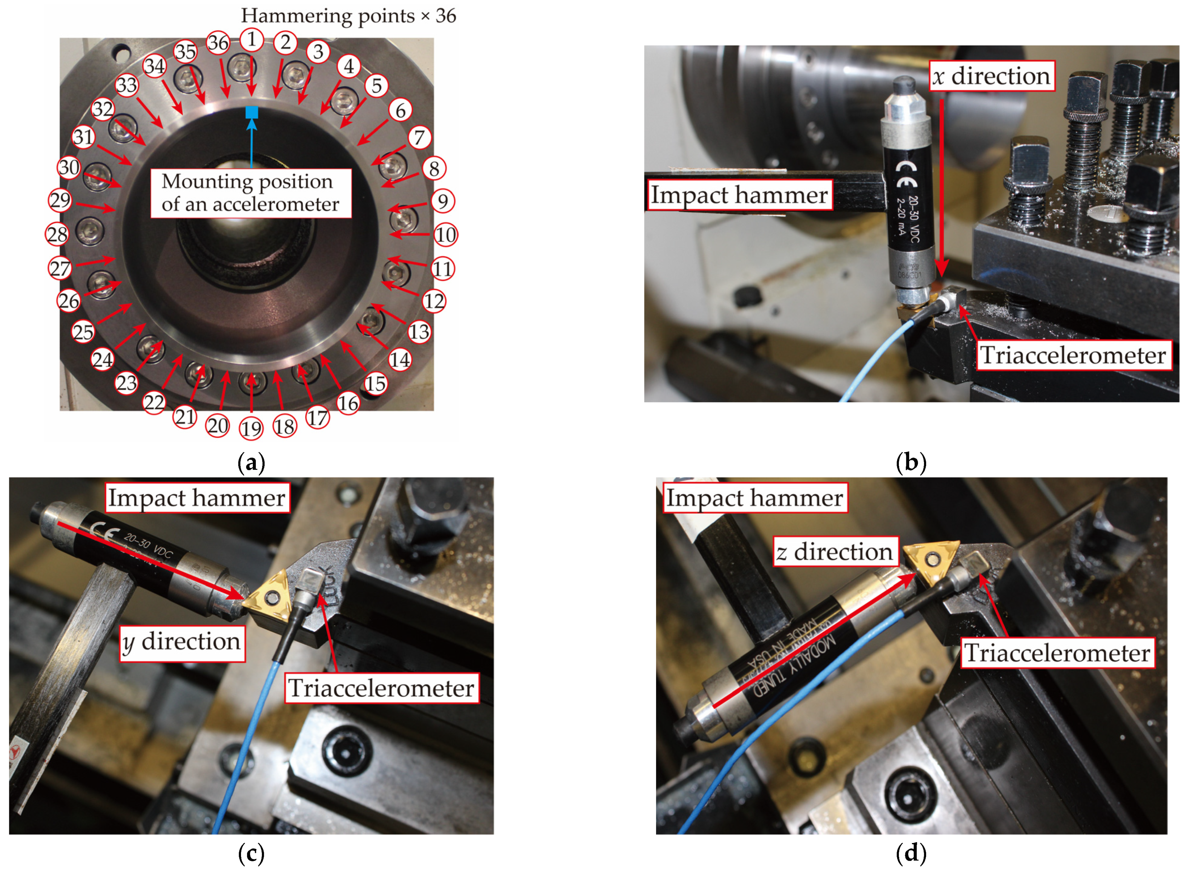
Impact tests for the workpiece and the cutting tool were conducted to identify their modal parameters. An accelerometer (Ono Sokki, NP-2106 (Kanagawa, Japan)) was attached to the tip of the workpiece in the radial direction and 36 hammering points at a regular pitch of 10°, were selected to measure the workpiece vibration modes using an impact hammer (PCB Piezotronics, Inc, 086C01 (Depew, NY, USA)) as portrayed in Figure 2a. A triaxial accelerometer (PCB Piezotronics, 356A03 (Depew, NY, USA)) was attached to the tip of the cutting tool and the frequency response functions of the cutting tool for 3 hammering directions were respectively measured using an impact hammer (PCB Piezotronics, Inc, 086C01 (Depew, NY, USA)) as depicted in Figure 2b–d. The overhang length of the tool from the tool stand to the tip of the tool was 25 mm.
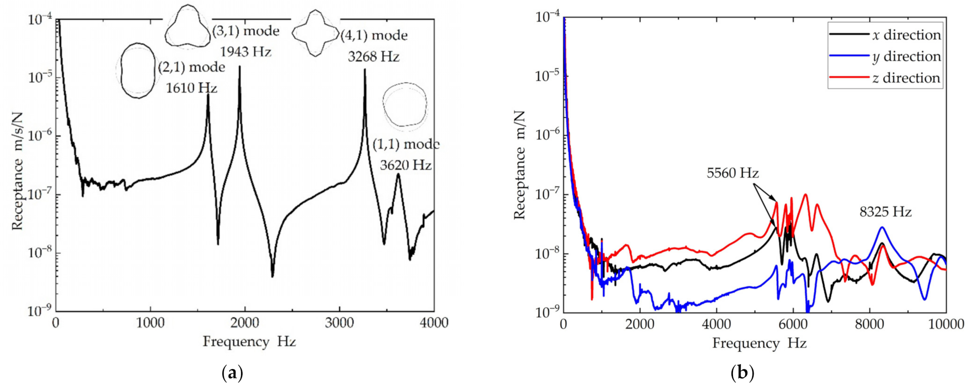
Figure 3a shows the frequency response function of the workpiece for a 4.0 mm wall thickness of the workpiece when its tip is hammered in the radial direction at the attachment point of the accelerometer. In addition, the vibration modes of the workpiece obtained from the experimental modal analysis at each peak frequency are presented in Figure 3a. The natural frequencies and damping ratios of the workpiece estimated by curve fitting the frequency response function are listed in Table 1, wherein m and n represent the number of nodes in the circumferential and longitudinal directions of the workpiece, respectively. As portrayed in Figure 3a, mode numbers (2, 1), (3, 1), and (4, 1) possess 4, 6, and 8 nodes in the circumferential direction, respectively. The (1, 1) mode in Figure 3a represents the first-order bending mode of the cantilevered workpiece. The frequency response functions of the tool in the 3 hammering directions are illustrated in Figure 3b. The black, blue, and red lines represent the tool frequency response function for hammering the tool in x, y, and z directions, respectively. The results of the tool impact test confirmed that the lowest natural frequency of the tool was approximately 5560 Hz, which was much higher than the natural frequency of the (4, 1) mode depicted in Figure 3a. Furthermore, the results of the cutting tests presented in the subsequent section revealed that the chatter frequencies were proximate to the natural frequencies of the shell modes of the workpiece; therefore, only the workpiece vibration modes were considered in the present study.

2.3. Chatter Vibration Mode

The present study focuses on the chatter generated during the finishing process of the external turning of a thin-walled cylindrical workpiece. The turning test in this study was performed on a CNC lathe (Takisawa Machine Tool Co., Ltd., TAC-510 (Okayama, Japan)). The cutting conditions in which the chatter could occur were determined from the preliminary cutting tests with varying cutting conditions. The width of cut was 0.025 mm, the cutting speed was 150 m/min, and the feed rate was 0.05 mm/rev for all the turning tests in this study. The cutting range was selected from the tip of the workpiece to 10 mm from the tip during feeding in the z-axis direction. To measure the workpiece vibration displacement in the radial direction during chatter generation, 9 eddy current sensors (Applied Electronics Corporation, PU-05 (Kanagawa, Japan)) were arranged at a regular pitch of 20° in the circumferential direction of the workpiece, as depicted in Figure 4a. The sensors were positioned at 5 mm in the axial direction from the tip of the workpiece, as shown in Figure 4b. In particular, sensor position #6 corresponds to the cutting point of the triangular insert (Tungaloy Corporation, TNMG160404-SS GH330 (Fukushima, Japan)), and the tool specifications are listed in Table 2. The occurrence of chatter was determined when the peak amplitude of the chatter frequency exceeded the threshold value at any one of the nine measurement points. The threshold value in the present work was defined as 3 μm, that is, ten times the resolution of the eddy current sensor.
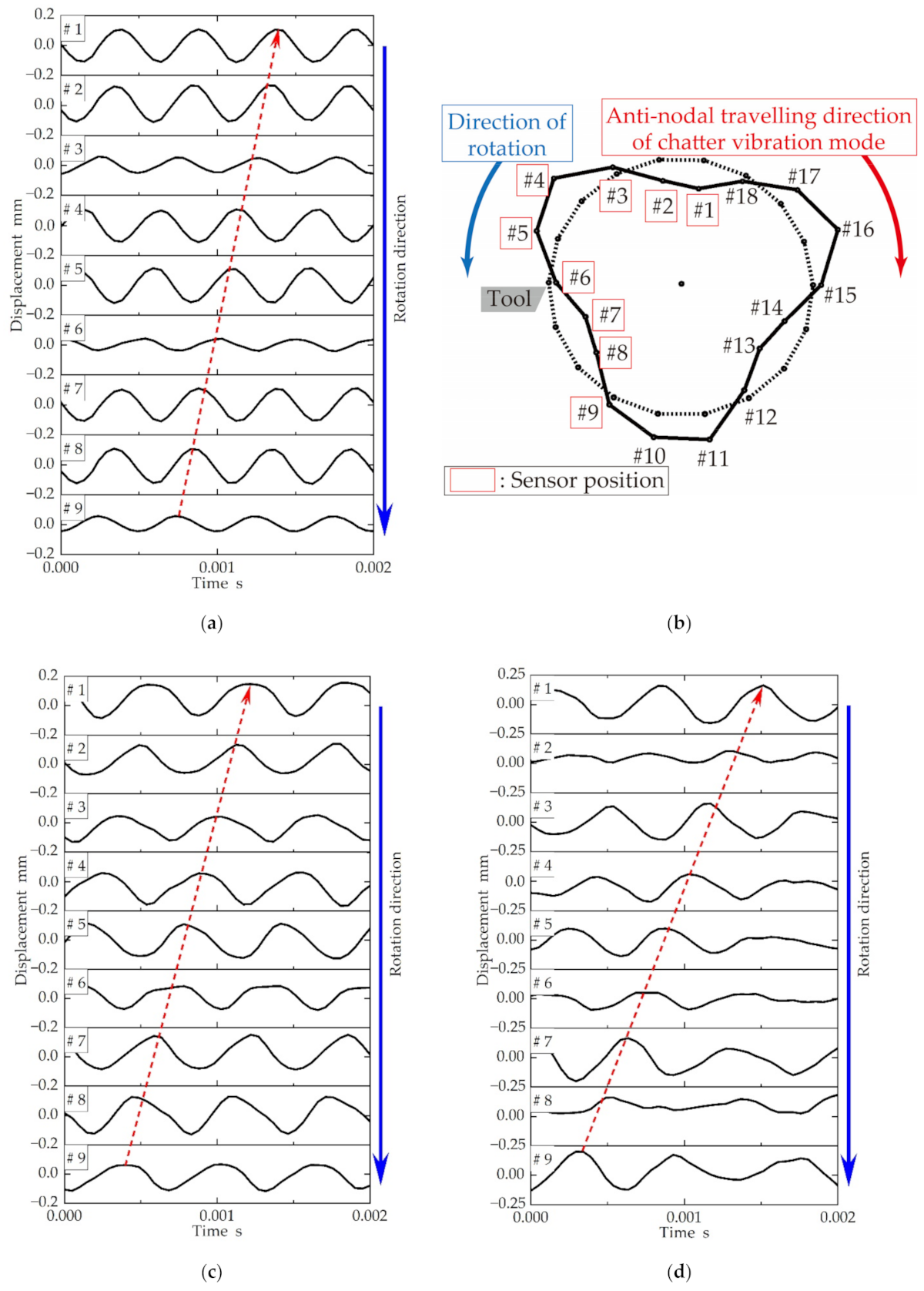
The waveforms of the workpiece vibration displacement in measuring points 1 to 9 during chatter generation are shown in Figure 5a for a 4.0 mm wall thickness of the workpiece. The frequency analysis of the workpiece vibration displacement during chatter generation (Figure 5a) indicated that the chatter frequency was 1995 Hz, which was approximately equal to the natural frequency of the (3, 1) mode of the workpiece (Figure 3a; Table 1). As observed from Figure 5a, the phase was almost inverted in comparison to the vibration waveforms of measuring points 2 and 4 or those of 5 and 7. The chatter vibration mode displayed in Figure 5b was obtained by interpolating the 9 measured vibration displacements, considering the symmetry of the workpiece vibration mode. The chatter vibration mode displayed in Figure 5b corresponds well with the (3, 1) mode exhibited in Figure 3a. The blue arrows in Figure 5a,b represent the rotational direction of the workpiece, whereas the red-dashed arrow in Figure 5a plots the position of the antinode of the workpiece vibration at each measurement point. As indicated in Figure 5a, the antinode positions travel in the direction opposite to the workpiece rotation with time. Therefore, the chatter vibration mode was observed to travel in the direction opposite to the workpiece rotation, as indicated by the red arrow in Figure 5b. In particular, the chatter vibration mode was not fixed in space. The waveforms of the workpiece vibration displacement in measuring points 1 to 9 during chatter generation are shown in Figure 5c,d for a 2.6 mm and a 1.5 mm thick wall, respectively. As observed from Figure 5c,d, the chatter vibration modes for the other 2 thick walls rotate asynchronously with the rotation of the workpiece, the same as the case of a 4 mm thick wall, displayed in Figure 5a.
The chatter frequencies resulting from the variations in the cylindrical workpiece wall thickness t are presented in Table 3. The decreasing workpiece wall thickness reduced the natural frequency of the workpiece; especially the natural frequency of (4, 1) mode was considerably reduced. As listed in Table 3, the decreasing wall thickness generated a higher order mode of chatter owing to the reduced rigidity of the workpiece. More precisely, the occurrence tendency of higher order modes with respect to the decreasing wall thickness was consistent with the results reported earlier by Kurita et al. [33]. For the wall thickness of 2.6 mm, the (4, 1) mode occurred while cutting in the vicinity of the workpiece tip, and the (3, 1) and (4, 1) modes occurred simultaneously while cutting 8.2 mm from the tip.

3. Experimental Verification of Chatter Suppression Effect with TMDs

Based on the chatter vibration modes discussed in Section 2, the influence of the mounting arrangement and tuning parameters of the TMDs on the chatter suppression during the turning process of a thin-walled cylinder was experimentally investigated. First, the specifications of the TMDs and the mounting method on the workpiece are discussed. Thereafter, the chatter suppression achieved by the TMD mounting arrangement in the circumferential and axial directions of the workpiece was examined for the chatter in a single vibration mode. In addition, the number and arrangement of the lightweight TMDs required to enhance the chatter suppression effect even with extremely lightweight TMDs were investigated under the condition of chatter generated by multiple vibration modes.

3.1. Specifications of TMD

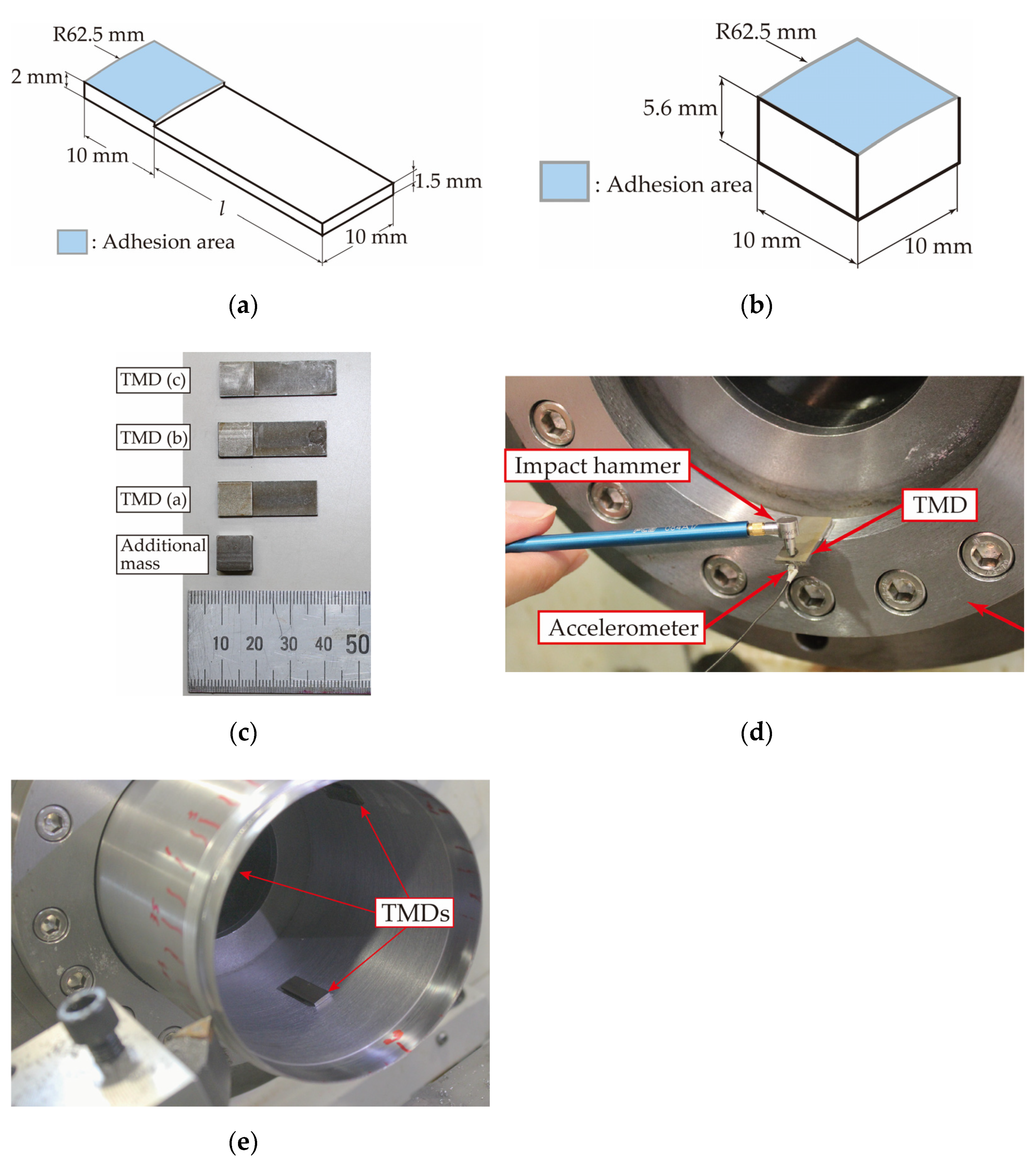
Based on the actual operating vibration measurement results during chatter generation, the shell mode with circumferential nodes was the dominant workpiece vibration mode. In the present study, the TMDs were attached to the inner surface of the rotating workpiece using double-sided tape for the metal. The dimensions of the TMDs are presented in Figure 6a. In general, TMDs are cantilevered beams with varying natural frequencies based on the beam length. The cantilever beam length l in Figure 6a was set to l = 19, 21.5, 24 mm. Moreover, an additional mass of approximately 5.0 g is depicted in Figure 6b almost equal to that of the TMD. The TMDs and the masses are made of carbon steel (C45). The masses are attached to the workpiece instead of the TMDs to compare the vibration characteristics of the workpiece and the chatter suppression effect. To install the TMDs or the masses inside the cylindrical workpiece, the curvature of the bonded part of the TMDs and the masses were altered to match the inner diameter of the workpiece, as portrayed in Figure 6a,b. The picture of the mass and the TMDs are presented in Figure 6c. An impact test of the TMDs, fixed to the ring jig with double-sided tape as depicted in Figure 6d, was conducted using an impact hammer (PCB Piezotronics, Inc, 086E80 (Depew, NY, USA)) under the boundary condition of the cantilevered beam to identify the modal parameters of the TMDs. An accelerometer (Ono Sokki, NP-2106 (Kanagawa, Japan)) was attached to the tip of the TMD with an adhesive. The natural frequencies and the damping ratios of the TMDs were obtained by curve fitting the measured frequency response function for each beam length of the TMD presented in Figure 7. The beam length l of the TMD, natural frequency fd, damping ratio ζd, and actual mass m of each TMD are presented in Table 4. A picture of the TMDs attached to the workpiece is presented in Figure 6e. The number of TMDs or masses was set to 3 or 4 to minimize the imbalance and deformation of the workpiece resulting from the centrifugal force. The TMDs with the same beam length l were manufactured such that their mass and natural frequency were equal. The mass of the workpiece was 2097 g. The mass ratio of the TMD or the additional mass to the workpiece was approximately 0.2%.

3.2. Effect of Various Circumferential Arrangements of TMDs on Chatter Suppression

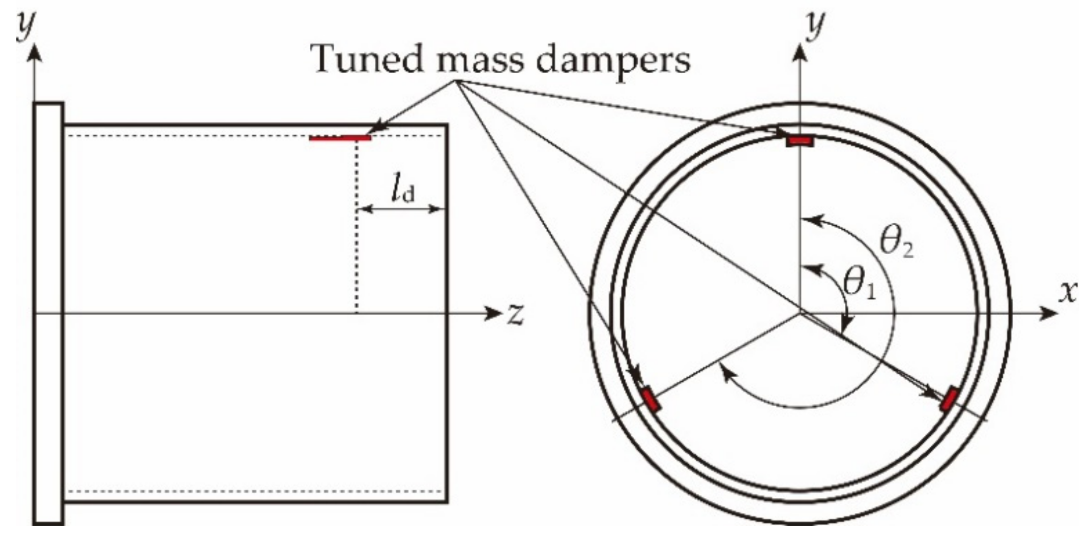
According to the experimental results presented in Section 2.3, the shell mode with 6 nodes in the circumferential direction was the predominant chatter vibration mode for the workpiece wall thickness of 4 mm. In a previous study [27], the vibration amplitude during chatter generation was reduced when three TMDs with a mass ratio of 1.5% to the workpiece mass were attached to the workpiece tip at an equal pitch in the circumferential direction. In addition, prior research has demonstrated that the installation of an additional mass with a mass ratio of 1.5% could reduce chatter vibration. Therefore, it was suggested that the chatter was reduced by the added mass rather than the influence of the TMD, for a sufficiently large mass ratio. However, the negative impacts of centrifugal forces, such as increased runout and deformation of the workpiece, become a concern if a large mass is added to a thin-walled cylinder. In the present study, the influence of the mounting position and the tuning parameters of the TMDs on chatter was investigated for extremely small mass ratio of the TMD (mass ratio of approximately 0.2%). The circumferential installation pitch of the TMDs or the masses was defined as the mounting angle θ1 and θ2 based on the TMDs or the masses mounted on the y-axis, as depicted in Figure 8. In particular, the mounting position of the TMDs or the masses in the z-axis direction was defined as the distance ld from the workpiece tip.
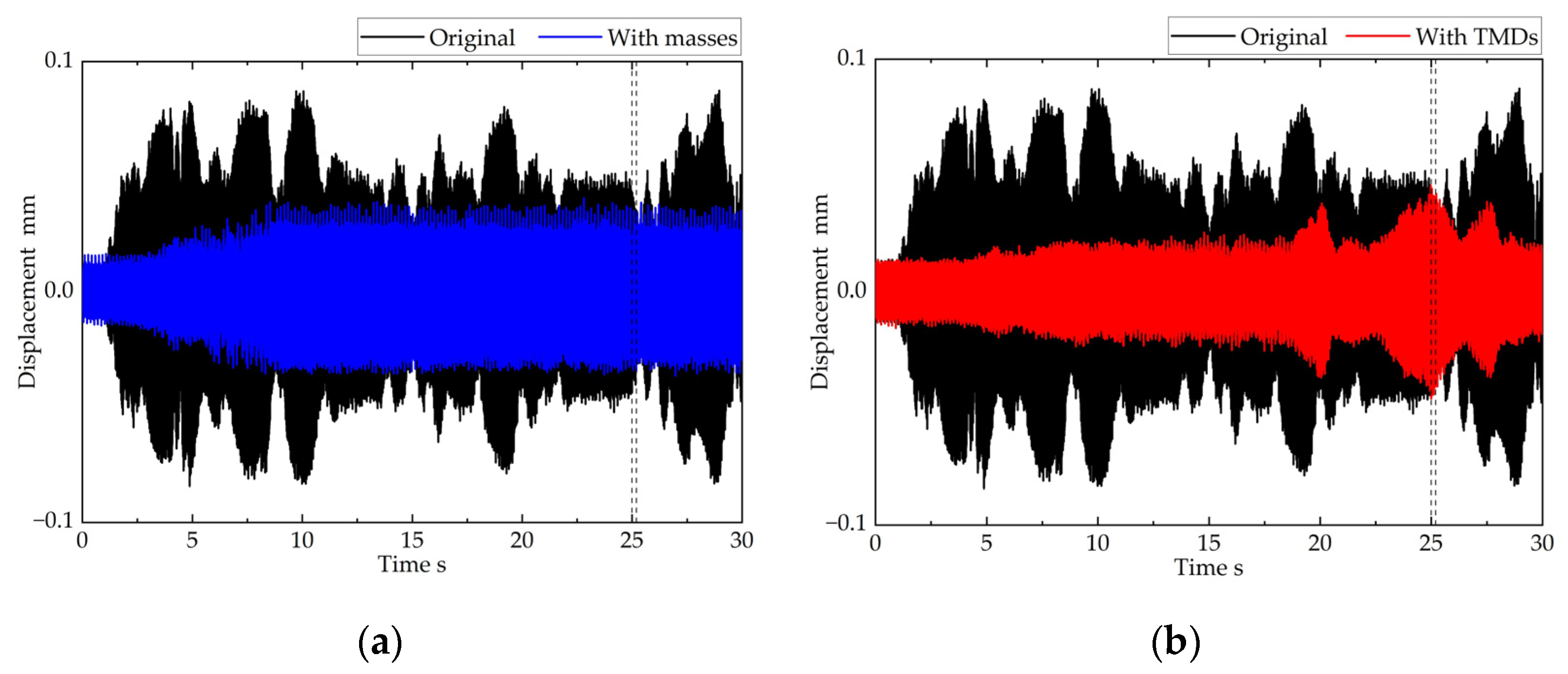
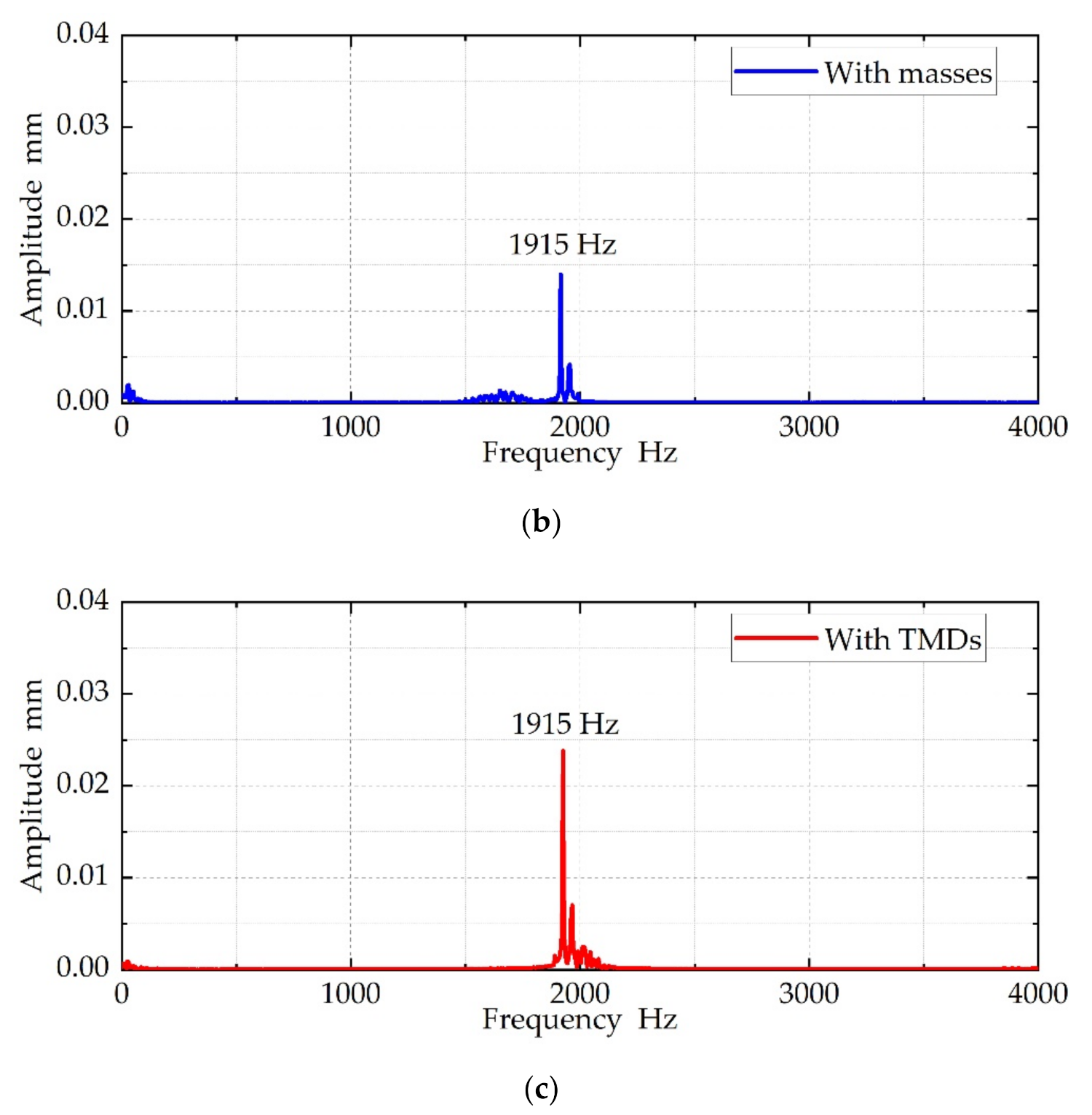
First, the chatter suppression effect was examined when three TMDs or three additional masses were installed at equally spaced positions in the circumferential direction the same as the mounting arrangement of the TMDs in the previous study [27]. The mounting angle of the TMDs or the masses in the circumferential direction were θ1 = θ2 = 120°. The mounting positions of all the TMDs or all the masses along the z-axis were ld = 35 mm. The natural frequencies of the adopted 3 TMDs were 1990 Hz close to the chatter frequency of (3,1) mode. The workpiece vibration waveforms measured by the eddy current sensor of #2 measuring point with and without the masses or TMDs are illustrated in Figure 9, which shows that the workpiece vibration amplitude during the chatter generation is reduced by adding the masses or TMDs; however, the chatter cannot be completely controlled. Figure 10 depicts the frequency analysis results of the workpiece vibration displacement with and without the masses or TMDs during cutting, 25 s after the initiation of cutting (at 7.6 mm from the workpiece tip). As observed from Figure 10b,c, the chatter frequency was observed upon attaching the masses or TMDs. Compared to the case of the mounted TMDs with a mass ratio of 1.5% arranged at an equal pitch in the circumferential direction in the previous study, the installation of the TMDs with a mass ratio of 0.2% did not reduce the chatter vibration very well.
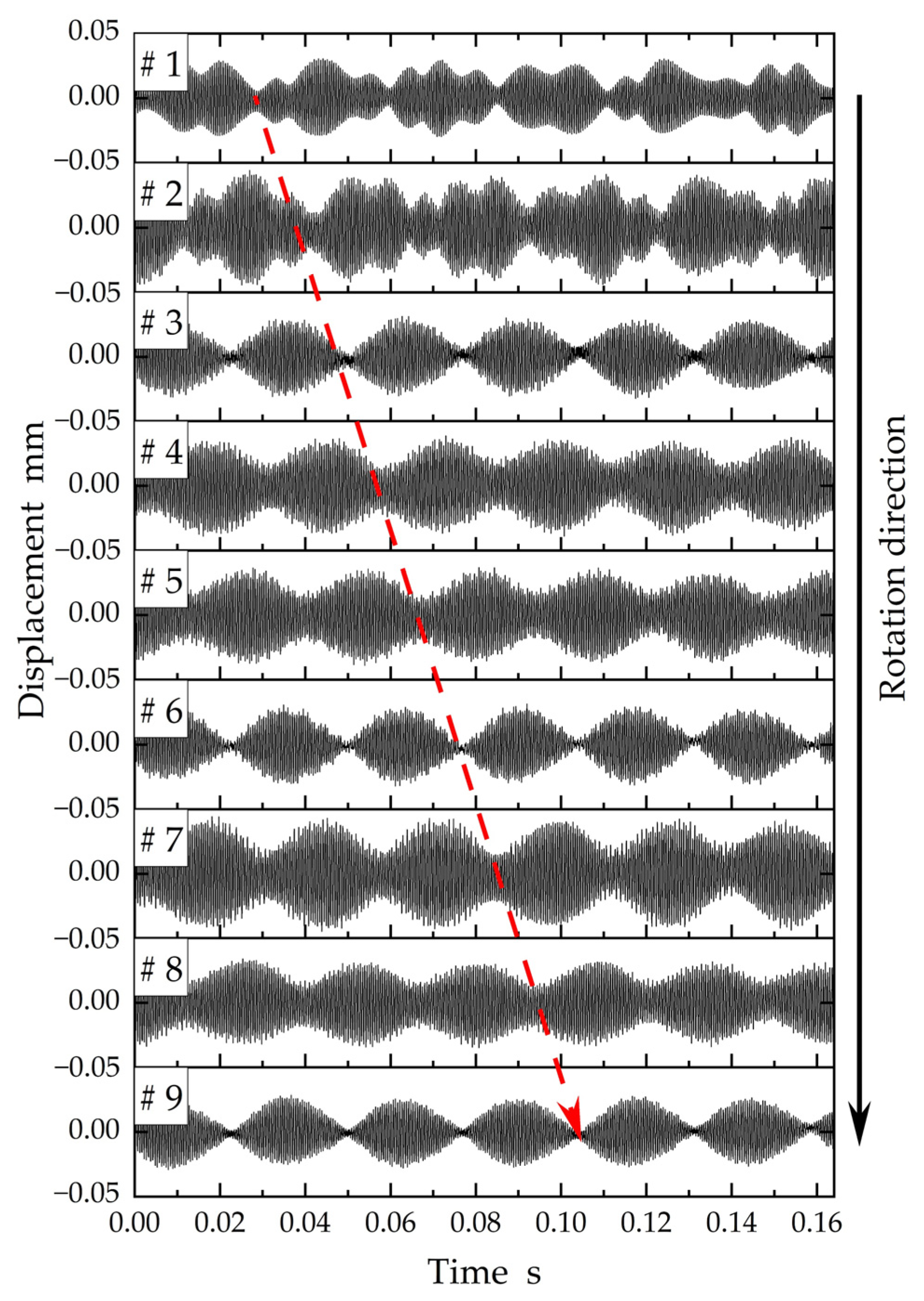
Figure 11 displays the results of enlarging the workpiece vibration waveforms at nine measuring points of the eddy current sensors during a single rotation cycle when the TMDs were installed. As indicated by the red-dashed arrows in Figure 11, the position corresponding to the vibration nodes at the nine measurement points moved forward by half a rotation in 0.08 s, which is half of the rotation period. Therefore, the period and direction of movement of the nodes coincided with the period and direction of rotation of the workpiece. In addition, the number of nodes during a single rotation cycle in the vibration waveform of each measurement point is six, which is consistent with the number of nodal diameters in the (3,1) mode of chatter vibration. The results of the workpiece vibration waveforms (Figure 11) suggest that the chatter vibration mode rotated in synchronisation with the workpiece rotation. We presumed that the chatter could not be completely suppressed since the mounting positions of the TMDs or the masses coincided with the positions of the nodes of the (3,1) mode of chatter vibration.
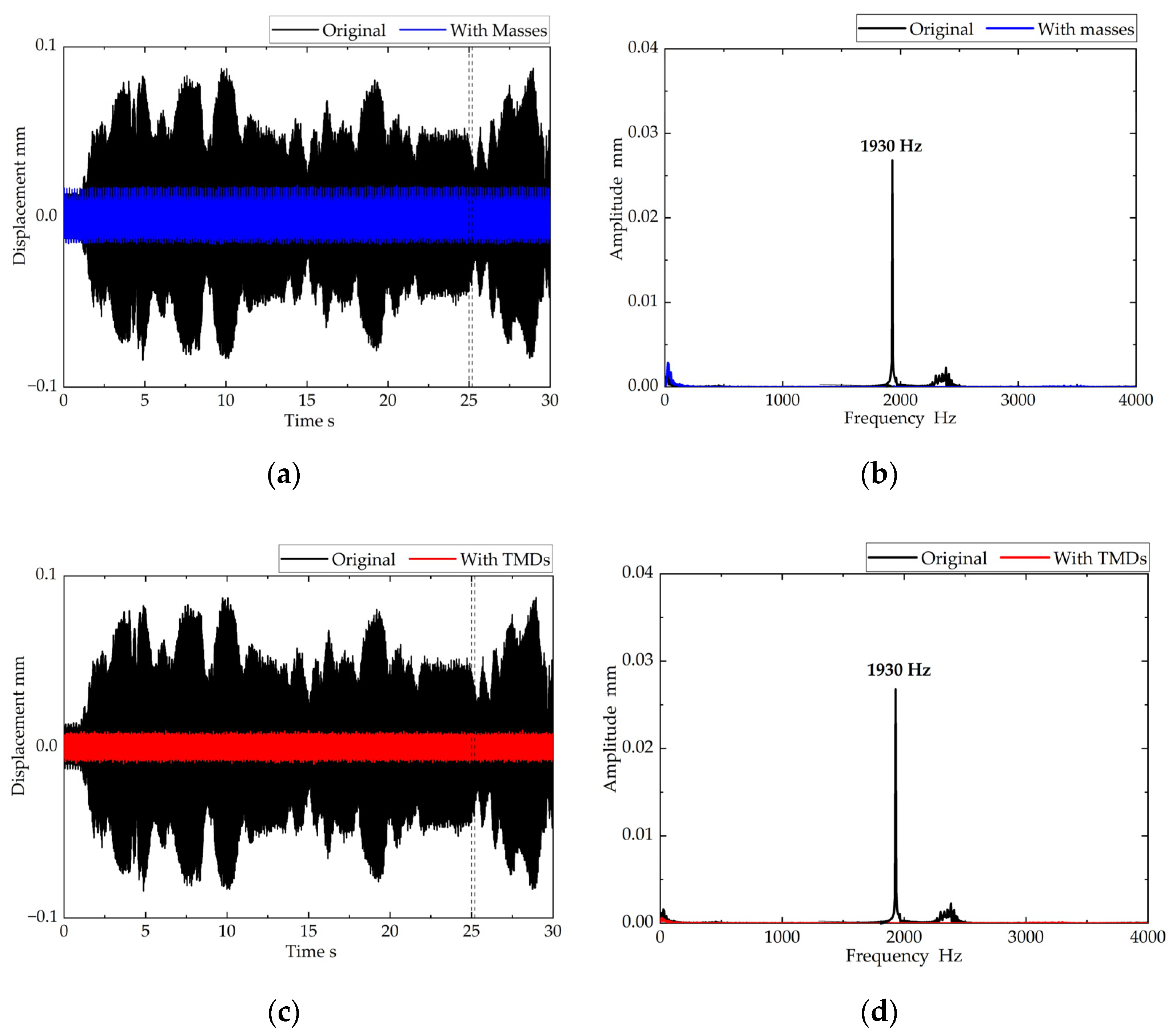
Next, we investigated the chatter suppression effect of the masses or TMDs arranged at an unequal pitch in the circumferential direction to avoid coincidence with the pitch of the nodes of the chatter vibration mode. The masses or TMDs were mounted at the workpiece tip (ld = 35 mm) with an unequal circumferential installation pitch, which did not coincide with the pitch of the vibration nodes of the (3,1) mode. The mounting position of the masses or TMDs was set to θ1 = 110° and θ2 = 220°, which was slightly displaced from the position of the node to avoid an excessive imbalance. The workpiece vibration waveforms measured by the eddy current sensor of number 2 measuring point with and without the masses or TMDs are presented in Figure 12a,c wherein the workpiece vibration amplitude was considerably reduced upon using both the masses and the TMDs. The frequency analysis results of the time waveforms for the 0.05 s period in the initial 25 s after cutting (vertical dotted line in Figure 12a,c are presented in Figure 12b,d). As observed from Figure 12, the chatter could be suppressed if the masses or TMDs were arranged such that their installation pitch did not coincide with the pitch of the nodes of the generated chatter vibration mode.

3.3. Effect of Various Equivalent Mass Ratios of TMD on Chatter Suppression

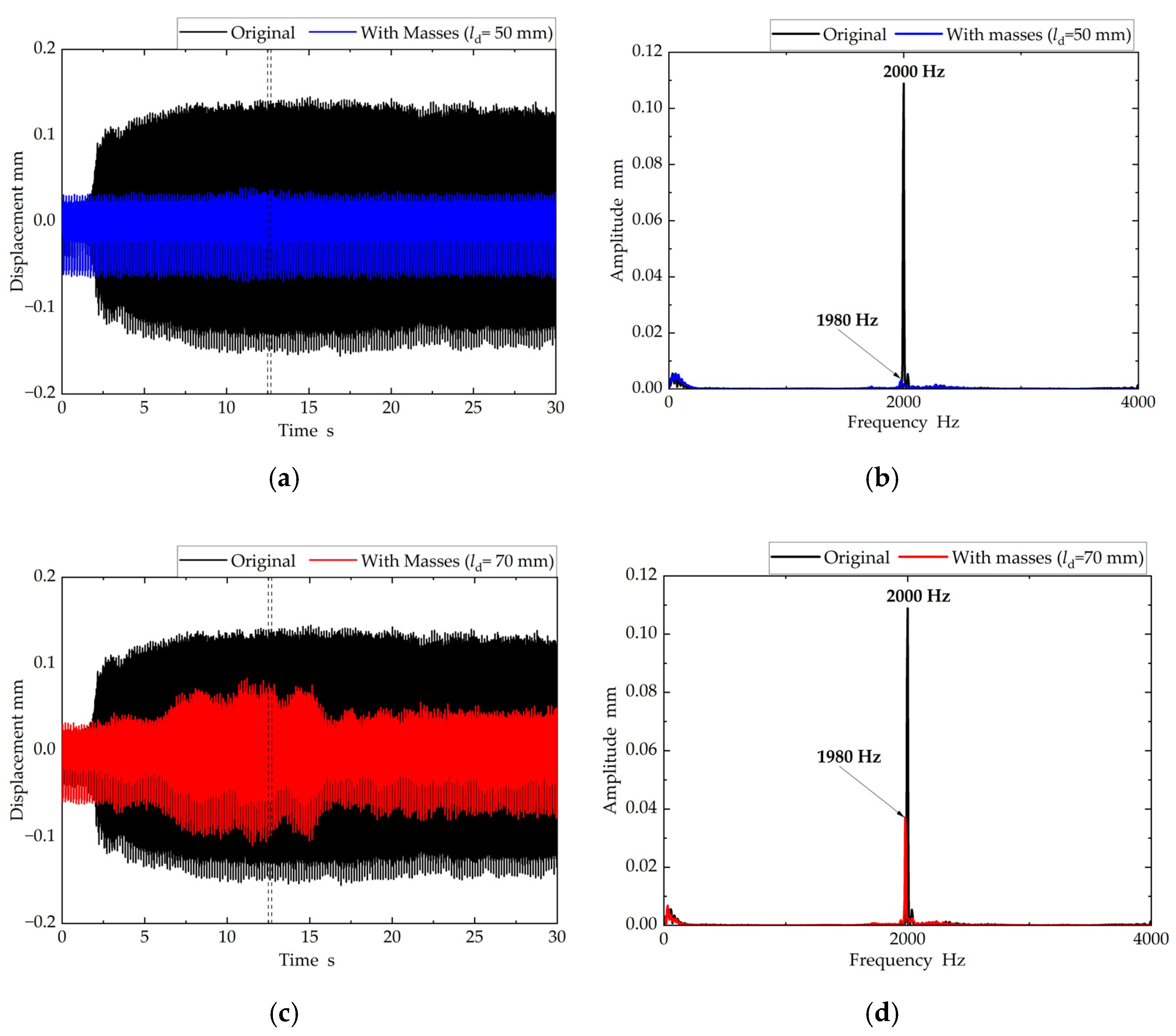
The chatter suppression effect was investigated upon further reducing the equivalent mass ratio of the additional mass or the TMD. The chatter vibration mode of the cantilever-supported workpiece exhibited the largest amplitude at the tip and the smallest amplitude at the fixed end of the workpiece. Therefore, when the mounting position of the masses or TMDs was moved towards the vicinity of the fixed end, the equivalent mass ratio of the masses or TMDs to that of the workpiece became smaller. The equivalent mass ratio is defined as the ratio of the actual mass of the additional mass (5.0 g) to the equivalent mass of the workpiece without the masses or TMDs in this paper. The equivalent mass of the workpiece for each mounting position ld was obtained by curve-fitting its frequency response functions at the tip when it was excited at ld = 35 mm, 50 mm, and 70 mm from the tip using an impact hammer (PCB Piezotronics, Inc, 086C01 (Depew, NY, USA)). The chatter suppression effect was verified when the masses or TMDs were mounted in the vicinity of the fixed end of the workpiece. First, the presence or absence of chatter was examined with the masses attached at ld = 50 mm or ld = 70 mm from the workpiece tip. The circumferential mounting arrangement of the masses was unequally spaced at θ1 = 110° and θ2 = 220°, similar to the case in Figure 12a, to compare with the case of ld = 35 mm discussed in Section 3.2. The equivalent mass ratios were 0.61% and 0.36% when the masses were added at ld = 50 mm and ld = 70 mm from the workpiece tip, respectively (equivalent mass ratio is 1.1% in the case of ld = 35 mm). The workpiece vibration waveforms measured by the eddy current sensor of number 2 measuring point for the masses attached at ld = 50 mm and ld = 70 mm from the tip are illustrated in Figure 13a,c respectively. The frequency analysis results of the time waveforms for the 0.05 s period in the initial 12.5 s after cutting (vertical dotted line in Figure 13a,c are presented in Figure 13b,d respectively. As observed from Figure 13a,b the chatter was mostly suppressed when the masses were attached at ld = 50 mm from the tip. In contrast, the chatter was generated when the masses were attached at ld = 70 mm from the tip. Therefore, the chatter could not be suppressed even if the masses with an equivalent mass ratio of less than 0.61% were unequally arranged in the circumferential direction to avoid coincidence with the pitch of the nodes of the chatter vibration mode.
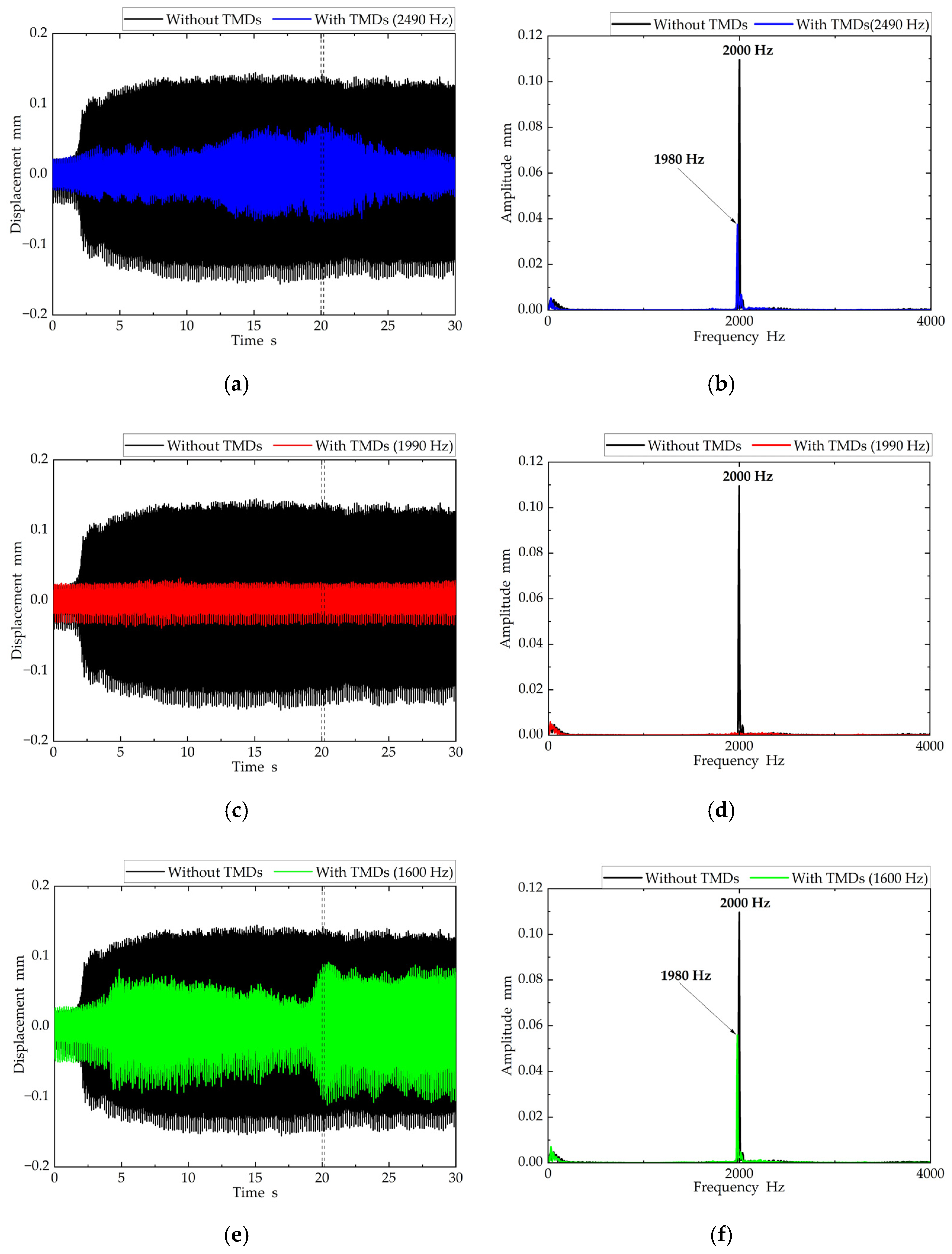
Next, the chatter suppression effect was examined for the TMDs mounted at ld = 70 mm from the workpiece tip. The circumferential mounting arrangement of the TMDs was unequally spaced at θ1 = 110° and θ2 = 220°, similar to the case in Figure 12c, to compare with the ld = 35 mm case discussed in Section 3.2. In addition, the chatter suppression effect was examined in case the natural frequency of the TMD deviated by approximately 20% from the chatter frequency. A comparison of the chatter suppression effect is presented in Figure 14 with varying natural frequencies of the TMD. The workpiece vibration waveforms measured by the eddy current sensor of number 2 measuring point with the natural frequencies of all three TMDs tuned to fd1 = fd2 = fd3 = 2490 Hz, fd1 = fd2 = fd3 = 1990 Hz, and fd1 = fd2 = fd3 =1600 Hz are presented in Figure 14a,c,e, respectively. The frequency analysis results of the time waveforms for the 0.05 s period in the initial 20 s after cutting (vertical dotted line in Figure 14a,c,e) are presented in Figure 14b,d,f, respectively. As observed from Figure 14, the chatter was suppressed only for the TMDs with the natural frequencies of fd1 = fd2 = fd3 = 1990 Hz. Thus, the chatter could be controlled even for an extremely small equivalent mass ratio of the TMDs with the natural frequency approximately equal to the chatter frequency.

3.4. Design for TMDs in Case of Multiple Modes of Chatter Generation

Table 3 in Section 2.3 revealed that chatter in both the (3,1) and (4,1) modes can occur simultaneously for a workpiece wall thickness of t = 2.6 mm. This section describes the chatter suppression effect of the TMDs mounting arrangements on multiple chatter modes. First, the suppression effect of multiple chatter modes was examined by installing three TMDs on the workpiece. The natural frequencies and circumferential installation pitch of the three TMDs are listed in Table 5. The natural frequencies of the TMDs were tuned to be close to the (3,1) mode and (4,1) mode chatter frequencies occurring for a wall thickness of 2.6 mm (Table 3). The mounting position of each TMD in the z-axis was ld = 35 mm from the workpiece tip. Figure 15a,b display the circumferential mounting arrangements of the TMDs superimposed on the (3,1) and (4,1) modes of chatter. The natural frequencies of the 3 TMDs in mounting arrangement A were tuned to the (3,1) mode chatter frequency for a single TMD and to the (4,1) mode chatter frequency for the others. The circumferential installation pitch of the two TMDs tuned to the (4,1) mode was determined such that it did not coincide with the pitch of the nodes of the (4,1) mode. The natural frequencies of the three TMDs in mounting arrangement B were tuned to the (4,1) mode chatter frequency for a single TMD and to the (3,1) mode chatter frequency for the others. The circumferential installation pitch of the two TMDs tuned to the (3,1) mode was determined such that it did not coincide with the pitch of the nodes of the (3,1) mode.
A comparison of the workpiece vibration waveforms measured by the eddy current sensor of #2 measuring point with and without the TMDs during the turning process for mounting arrangement A is presented in Figure 16a. In addition, the root mean square (RMS) values of the workpiece vibration displacement with and without the TMDs from the start time to the end time of cutting are displayed in Figure 16a. The frequency analysis of the time waveform for the 0.05 s period in the initial 28 s after cutting (vertical dotted line in Figure 16a) is presented in Figure 16b. The results presented in Figure 16 suggest that the (4,1) mode chatter can be suppressed even when the number of the TMDs with natural frequencies close to the (4,1) mode chatter frequency is 2. On the other hand, the (3,1) mode chatter vibration cannot be suppressed when only 1 TMD with a natural frequency close to the (3,1) mode chatter frequency is used.
A comparison of the workpiece vibration waveforms measured by the eddy current sensor of 2 measuring point and the RMS values with and without the TMDs during the turning process for mounting arrangement B is presented in Figure 17a. The frequency analysis of the time waveform for the 0.05 s period in the initial 28 s after cutting (vertical dotted line in Figure 17a) is presented in Figure 17b. The results presented in Figure 17 suggest that the (3,1) mode chatter can be largely suppressed even when the number of the TMDs with natural frequencies close to the (3,1) mode chatter frequency is 2. On the other hand, the (4,1) mode chatter vibration cannot be sufficiently suppressed when only 1 TMD with a natural frequency is close to the (4,1) mode chatter frequency is used.
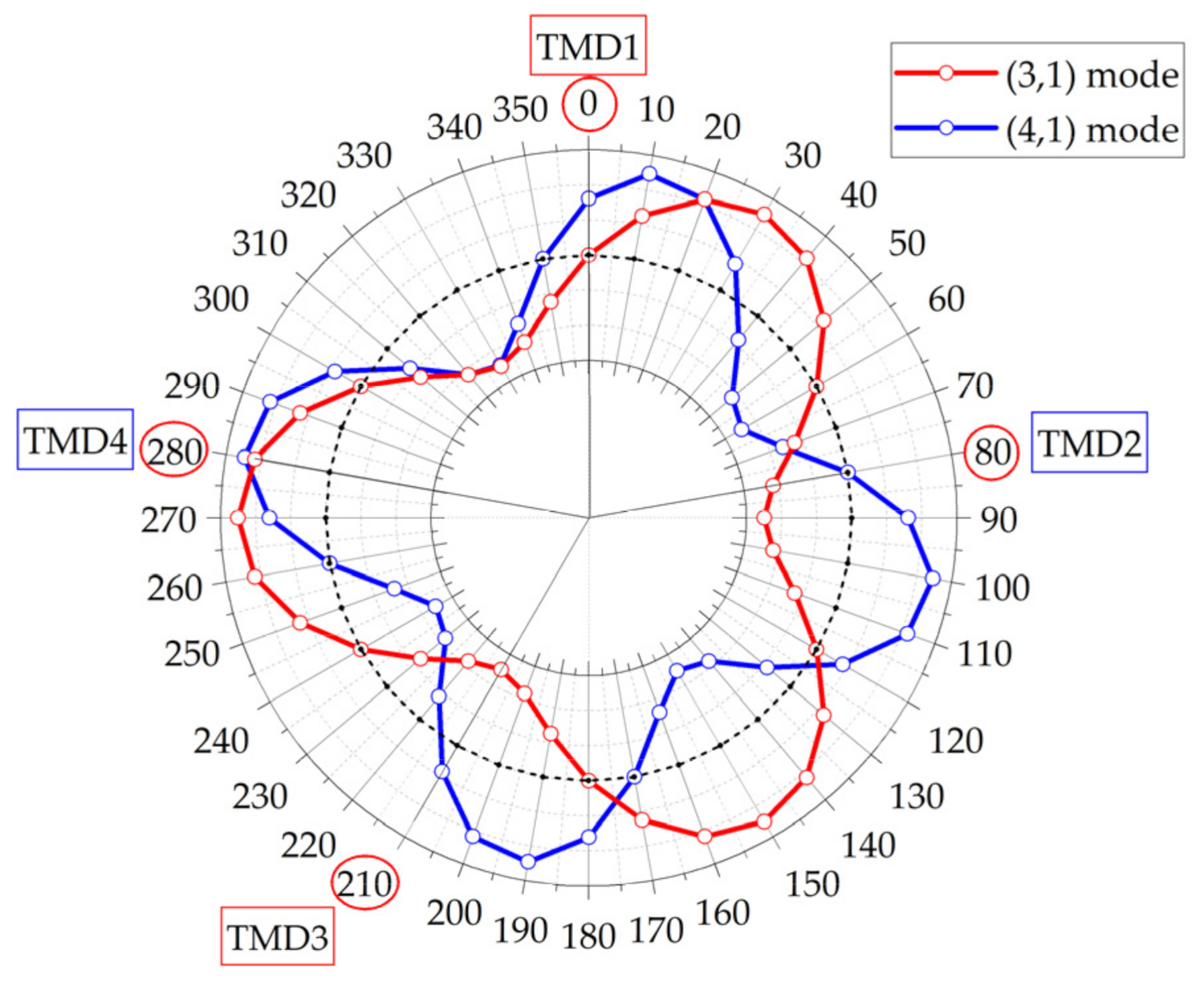
The results presented in Figure 16 and Figure 17 suggest that at least two TMDs with natural frequencies close to the chatter frequency of each mode are required to suppress the chatter of each mode. Therefore, the suppression effect of multiple chatter modes was examined by respectively installing two TMDs with natural frequencies close to chatter frequencies of (3,1) mode and (4,1) mode. The circumferential installation pitches of the four TMDs tuned to the (3,1) and (4,1) modes were determined such that they did not coincide with the pitch of the nodes of the (3,1) and (4,1) modes, respectively. The natural frequencies and circumferential installation pitches of each of the four TMDs are listed in Table 6. The circumferential mounting arrangement of the TMDs were superimposed on the (3,1) and (4,1) modes of chatter, as depicted in Figure 18. Moreover, the position of each TMD in the z-axis was ld = 35 mm from the workpiece tip.
The workpiece vibration waveforms measured by the eddy current sensor of number 2 measuring point and the RMS values with and without the TMDs during the turning process for mounting arrangement C are presented in Figure 19a. The frequency analysis of the time waveform for the 0.05 s period in the initial 28 s after cutting (vertical dotted line in Figure 19a) is presented in Figure 19b, wherein the peak of the chatter frequency in the (3, 1) mode slightly appears for the case of mounting arrangement C with the four TMDs. However, the RMS values of the workpiece vibration displacement with the TMDs (Figure 19a) were significantly reduced in comparison to those in Figure 16a and Figure 17a. Although the task of investigating the TMDs’ mounting arrangements to have a further chatter suppression effect remains, the experimental results in Figure 19 suggested that, in order to suppress the multiple chatter modes using small mass ratio TMDs, the TMDs are required to be placed at unequal intervals and at least two TMDs ought to be attached for each chatter vibration mode.

4. Discussion

The experimental results in Section 3 suggest that the chatter suppression effect can be enhanced by arranging the TMDs or the additional masses to avoid coincidence with the spacing of the nodes of the chatter vibration mode. This section considers the reasons for this improvement in the chatter suppression effect when the circumferential installation pitch of the TMDs is not aligned with the pitch of the nodes of the chatter vibration mode.
First, the chatter suppression effect of the mounting arrangement of the TMDs is discussed by comparing the chatter vibration modes with and without the TMDs. As depicted in Figure 5a,c,d the observation results of chatter vibration mode of the workpiece without the additional masses or the TMDs suggested that the chatter vibration mode was the shell mode with circumferential nodes and that it rotated asynchronously with respect to the workpiece rotation. As the cylindrical workpiece is symmetrical without the additional masses or the TMDs, the workpiece has two degenerate eigenmodes that are out-of-phase by 90°. In the occurrence of chatter without the masses or TMDs, the chatter vibration of the (3,1) mode, Rm,s(θ,t), can be expressed as a superposition of two degenerate modes as follows:
R m , s ( θ , t ) = C m , s cos ω t cos m θ + D m , s sin ω t sin m θ
where t denotes the time variable, θ represents the angular coordinate on the workpiece based on the mounting angle position of TMD 1, Cm,s and Dm,s represent the amplitude of the cosine and sine modes of the (m,s) mode, respectively, and ω denotes the angular frequency of chatter. According to Equation (1), the chatter vibration mode rotates asynchronously with respect to the workpiece rotation when the amplitudes of the two modes are nearly equal. In contrast, the chatter vibration mode rotates synchronously with the workpiece rotation, as observed in Figure 11, when the circumferential installation pitch of the TMDs is equally distributed to ensure coincidence with the node position of the chatter vibration mode. The reason for this synchronous rotation with the workpiece with equally spaced TMDs can be inferred from Equation (1), as follows. The mode in which the mounting position of the TMDs coincided with the antinode position of the degenerate mode was suppressed, whereas the mode in which the mounting position coincided with the node position of the degenerate mode was amplified directly into the self-excited vibration. The mode with the reference TMD1 mounting position as a node corresponds to the sine mode in Equation (1), whereas the mode with the TMD1 mounting position as an anti-node corresponds to the cosine mode in Equation (1). Thus, the amplitude of the cosine mode was reduced by the TMDs owing to the anti-node positions of the TMDs. However, the amplitude of the sine mode was not reduced because the TMDs were located at the node positions, that is, the TMDs influenced only one of the degenerate modes. Eventually, we concluded that the chatter vibration mode can rotate synchronously with the workpiece rotation because only the sine mode was amplified as the chatter vibration mode. Based on the considerations mentioned above, we conclude that the TMDs can influence both the degenerate modes and can effectively control chatter when the circumferential installation pitch of the TMDs is not equal to the pitch of the nodes of the chatter vibration mode.
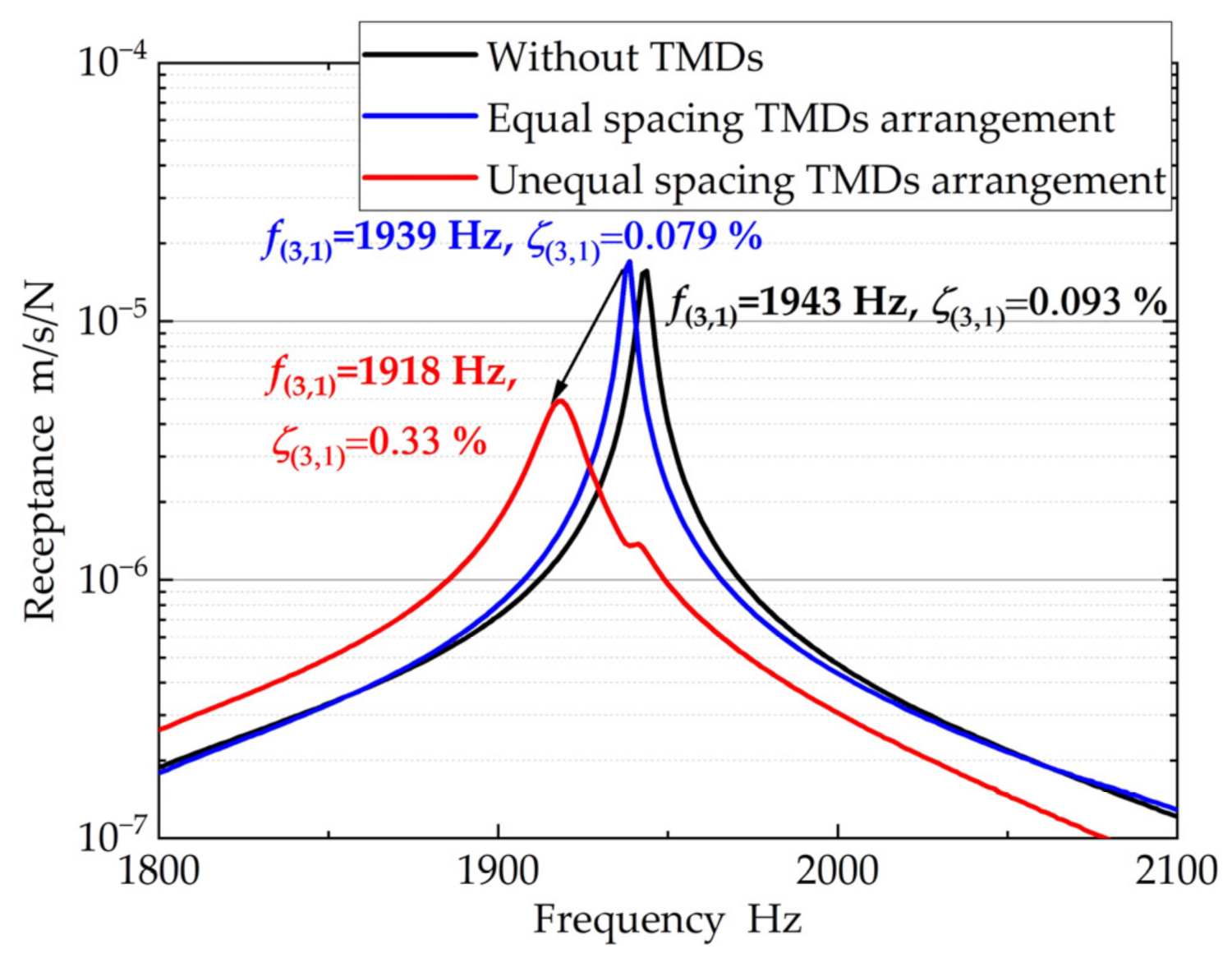
Next, the workpiece frequency response with the TMDs arranged with a regular pitch (TMD mounting arrangement in Figure 9b) and an irregular pitch (TMD mounting arrangement in Figure 12c) in the circumferential direction along with the workpiece frequency response without the TMDs are presented in Figure 20. It can be seen from Figure 20 that the peak of the natural frequency of the (3,1) mode related to the chatter mode in the case of the TMDs arranged with a regular pitch is almost the same as that of the original workpiece without the TMDs. In contrast, the peak becomes lower and the modal damping ratio is higher in the case of the TMDs arranged with an irregular pitch compared to that of the TMDs arranged with a regular pitch.
The present study demonstrated the chatter suppression effect in specific patterns with the irregular circumferential installation pitch of the TMDs. Based on the experimental results, an analytical model will be developed to determine the optimum arrangement and tuning parameters of the TMDs to further enhance the chatter suppression effect, by considering the amount of imbalance.

5. Conclusions

This study proposed a method for effectively suppressing the chatter during the turning process of thin-walled cylinders using lightweight TMDs. The major conclusions are summarised as follows:
(1)
The chatter can be controlled if the masses or TMDs are attached to the workpiece such that their mounting arrangements do not coincide with the spacing of the nodes of the generated chatter vibration mode.
(2)
In case the TMDs are attached to the fixed end of the workpiece, the natural frequencies of the TMDs must be adjusted approximately to the chatter frequency for obtaining a sufficient chatter suppression effect.
(3)
To suppress multiple chatter modes using the TMDs, the TMDs ought to be placed at unequal intervals and at least two attached TMDs should be tuned for each chatter vibration mode.
The present study demonstrated the chatter suppression effect in specific mounting arrangements of the TMDs. In order to extend the effectiveness of the proposed method, we are going to further make some experimental verifications, such as evaluation of the reproducibility of the experimental results considering the effects of cutting conditions, machining effect of the workpiece, and tool wear on the chatter suppression effect. Moreover, the development of an analytical model regarding chatter in the finishing process of the external turning of a thin-walled cylindrical workpiece with the TMDs and the derivation of the optimum tuning parameters of the TMDs, including the mounting arrangement, could further enhance the chatter suppression effect.

Author Contributions

Conceptualisation and methodology, Y.N.; software, Y.N. and T.K.; validation, Y.N., H.T. and T.K.; investigation, Y.N., H.T. and T.K.; data curation, Y.N.; writing—original draft preparation, Y.N.; writing—review and editing, Y.N. and H.T.; visualisation, T.K. and Y.N.; supervision, Y.N.; project administration, Y.N. All authors are responsible for the contents and have read and approved the manuscript for submission. All authors have read and agreed to the published version of the manuscript.

Funding

This research received no external funding.

Acknowledgments

The authors would like to thank Atsushi Sakuma, an undergraduate student at the Tokyo Institute of Technology, for the experiments and Toru Inoue, a technical specialist at the Tokyo Institute of Technology, for the technical support. We would like to thank Editage (www.editage.com (accessed on 15 December 2021)) for English language editing services.

Conflicts of Interest

The authors declare no conflict of interest.

References

  1. Kolluru, K.; Axinte, D. Coupled interaction of dynamic responses of tool and workpiece in thin wall milling. J. Mater. Process. Technol. 2013, 213, 1565–1574. [Google Scholar] [CrossRef]
  2. Chanda, A.; Fischer, A.; Eberhard, P.; Dwivedy, S.K. Stability analysis of a thin-walled cylinder in turning operation using the semi-discretization method. Acta Mech. Sin. 2014, 30, 214–222. [Google Scholar] [CrossRef]
  3. Song, Q.; Liu, Z.; Wan, Y.; Ju, G.; Shi, J. Application of Sherman–Morrison–Woodbury formulas in instantaneous dynamic of peripheral milling for thin-walled component. Int. J. Mech. Sci. 2015, 96–97, 79–90. [Google Scholar] [CrossRef]
  4. Gerasimenko, A.; Guskov, M.; Gouskov, A.; Lorong, P.; Shokhin, A. Analytical modeling of a thin-walled cylindrical workpiece during the turning process. Stability analysis of a cutting process. J. Vibroeng. 2017, 19, 5825–5841. [Google Scholar] [CrossRef] [Green Version]
  5. Irene, D.S.; Asuncion, R.; Norberto, L.L.L.; Juan, G.A. Thin-wall machining of light alloys: A review of models and industrial approaches. Materials 2019, 12, 2012. [Google Scholar] [CrossRef] [Green Version]
  6. Quintana, G.; Ciurana, J. Chatter in machining processes: A review. Int. J. Mach. Tools Manuf. 2011, 51, 363–376. [Google Scholar] [CrossRef]
  7. Munoa, J.; Beudaert, X.; Dombovari, Z.; Altintas, Y.; Budak, E.; Brecher, C.; Stepan, G. Chatter suppression techniques in metal cutting. CIRP Ann. Manuf. Technol. 2016, 65, 785–808. [Google Scholar] [CrossRef]
  8. Matsubara, A.; Taniyama, Y.; Wang, J.; Kono, D. Design of a support system with a pivot mechanism for suppressing vibrations in thin-wall milling. CIRP Ann. Manuf. Technol. 2017, 66, 381–384. [Google Scholar] [CrossRef]
  9. Fei, J.; Lin, B.; Xiao, J.; Ding, M.; Yan, S.; Zhang, X.; Zhang, J. Investigation of moving fixture on deformation suppression during milling process of thin-walled structures. J. Manuf. Process. 2018, 32, 403–411. [Google Scholar] [CrossRef]
  10. Croppi, L.; Grossi, N.; Scippa, A.; Campatelli, G. Fixture Optimization in Turning Thin-Wall Components. Machines 2019, 7, 68. [Google Scholar] [CrossRef] [Green Version]
  11. Guo, L.; Yang, F.; Li, T.; Zhou, M.; Tang, J. Vibration suppression of aeroengine casing during milling. Int. J. Adv. Manuf. Technol. 2021, 113, 295–307. [Google Scholar] [CrossRef]
  12. Zeng, S.; Wan, X.; Li, W.; Yin, Z.; Xiong, Y. A novel approach to fixture design on suppressing machining vibration of flexible workpiece. Int. J. Mach. Tools Manuf. 2012, 58, 29–43. [Google Scholar] [CrossRef]
  13. Fischer, A.; Eberhard, P. Simulation-Based Stability Analysis of a Thin-Walled Cylinder During Turning with Improvements Using an Adaptronic Turning Chisel. Arch. Mech. Eng. 2011, 58, 367–391. [Google Scholar] [CrossRef] [Green Version]
  14. Ma, H.; Wu, J.; Yang, L.; Xiong, Z. Active chatter suppression with displacement-only measurement in turning process. J. Sound Vib. 2017, 401, 255–267. [Google Scholar] [CrossRef]
  15. Fallah, M.; Moetakef-Imani, B. Adaptive inverse control of chatter vibrations in internal turning operations. Mech. Syst. Signal Process. 2019, 129, 91–111. [Google Scholar] [CrossRef]
  16. Lu, X.; Chen, F.; Altintas, Y. Magnetic actuator for active damping of boring bars. CIRP Ann. Manuf. Technol. 2014, 63, 369–372. [Google Scholar] [CrossRef]
  17. Kishore, R.; Choudhury, S.K.; Orra, K. On-line control of machine tool vibration in turning operation using electro-magneto rheological damper. J. Manuf. Process. 2018, 31, 187–198. [Google Scholar] [CrossRef]
  18. Yigit, U.; Cigeroglu, E.; Budak, E. Chatter reduction in boring process by using piezoelectric shunt damping with experimental verification. Mech. Syst. Signal Process. 2017, 94, 312–321. [Google Scholar] [CrossRef]
  19. Falta, J.; Janota, M.; Sulitka, M. Chatter suppression in finish turning of thin-walled cylinder: Model of tool workpiece interaction and effect of spindle speed variation. Procedia CIRP 2018, 77, 175–178. [Google Scholar] [CrossRef]
  20. Otto, A.; Radons, G. Application of spindle speed variation for chatter suppression in turning. CIRP J. Manuf. Sci. Technol. 2013, 6, 102–109. [Google Scholar] [CrossRef]
  21. Beri, B.; Meszaros, G.; Stepan, G. Machining of slender workpieces subjected to time-periodic axial force: Stability and chatter suppression. J. Sound Vib. 2021, 504, 116114. [Google Scholar] [CrossRef]
  22. Liu, Y.; Liu, Z.; Song, Q.; Wang, B. Analysis and implementation of chatter frequency dependent constrained layer damping tool holder for stability improvement in turning process. J. Mater. Process. Technol. 2019, 266, 687–695. [Google Scholar] [CrossRef]
  23. Kolluru, K.; Axinte, D.; Becker, A. A solution for minimizing vibrations in milling of thin walled casings by applying dampers to workpiece surface. CIRP Ann. Manuf. Technol. 2013, 62, 415–418. [Google Scholar] [CrossRef] [Green Version]
  24. Tarng, Y.S.; Kao, J.Y.; Lee, E.C. Chatter suppression in turning operations with a tuned vibration absorber. J. Mater. Process. Technol. 2000, 105, 55–60. [Google Scholar] [CrossRef]
  25. Nakano, Y.; Takahara, H.; Kondo, E. Countermeasure against chatter in end milling operations using multiple dynamic ab-sorbers. J. Sound Vib. 2013, 332, 1626–1638. [Google Scholar] [CrossRef]
  26. Bansal, A.; Law, M. A receptance coupling approach to optimally tune and place absorbers on boring bars for chatter sup-pression. Procedia CIRP 2018, 77, 167–170. [Google Scholar] [CrossRef]
  27. Nakano, Y.; Kishi, T.; Takahara, H.; Croppi, L.; Scippa, A. Experimental Investigation on the Effect of Tuned Mass Damper on Mode Coupling Chatter in Turning Process of Thin-Walled Cylindrical Workpiece. In Proceedings of the 18th Asia-Pacific Vibration Conference, The University of Technology Sydney, Sydney, Australia, 18–20 November 2019. [Google Scholar]
  28. Seto, K.; Tominari, N. Effect of a Variable Stiffness-Type Dynamic Damper on Machine Tools with Long Overhung Ram. Bull. JSME 1976, 19, 1270–1277. [Google Scholar] [CrossRef]
  29. Wang, M.; Zan, T.; Yang, Y.; Fei, R. Design and implementation of nonlinear TMD for chatter suppression: An application in turning processes. Int. J. Mach. Tools Manuf. 2010, 50, 474–479. [Google Scholar] [CrossRef]
  30. Yang, Y.; Muñoa, J.; Altintas, Y. Optimization of multiple tuned mass dampers to suppress machine tool chatter. Int. J. Mach. Tools Manuf. 2010, 50, 834–842. [Google Scholar] [CrossRef]
  31. Sims, N.D. Vibration absorbers for chatter suppression: A new analytical tuning methodology. J. Sound Vib. 2007, 301, 592–607. [Google Scholar] [CrossRef] [Green Version]
  32. Chang, J.Y.; Lai, G.J.; Chen, M.F. A study on the chatter characteristics of the thin wall cylindrical workpiece. Int. J. Mach. Tools Manuf. 1994, 34, 489–498. [Google Scholar] [CrossRef]
  33. Kurita, Y.; Oura, Y.; Tanaka, T.; Kawata, M. Chatter vibration of workpiece deformation type in cutting thin-walled cylindrical workpiece (Generation mechanism of chatter vibration). Trans. JSME 2020, 86, 1–15. [Google Scholar] [CrossRef]
Figure 1. Workpiece dimensions and attachment of workpiece to lathe: (a) Dimensions of workpiece; (b) Workpiece attached to lathe; (c) Expanded view of workpiece fixation.
Applsci 11 12070 g001
Figure 2. Mounting position of accelerometer and hammering points for workpiece and tool impact test: (a) Measuring points of workpiece; (b) Measuring points of tool in x direction; (c) Measuring points of tool in y direction; (d) Measuring points of tool in z direction.
Applsci 11 12070 g002
Figure 3. Frequency response functions: (a) Workpiece frequency response function for a 4.0 mm wall thickness of the workpiece; (b) Tool frequency response function in x, y, and z directions.
Applsci 11 12070 g003
Figure 4. Measurement positions of workpiece vibration displacement: (a) Eddy current sensors arrangement; (b) Eddy current sensors’ position along with z-axis.
Applsci 11 12070 g004
Figure 5. Vibration displacement of the workpiece from #1 to #9 during chatter generation: (a) Vibration waveforms of 9 measuring points for a 4.0 mm thick wall of the workpiece; (b) Eddy current sensors arrangement in the circumferential direction; (c) Vibration waveforms of 9 measuring points for a 2.6 mm thick wall of the workpiece; (d) Vibration waveforms of 9 measuring points for a 1.5 mm thick wall of the workpiece.
Applsci 11 12070 g005
Figure 6. TMD and additional mass: (a) TMD dimensions; (b) Additional mass dimensions; (c) Picture of additional mass and TMDs; (d) Impact test of TMD; (e) Picture of TMDs attached to the workpiece.
Applsci 11 12070 g006
Figure 7. Frequency response functions for each beam length TMD.
Applsci 11 12070 g007
Figure 8. Mounting position of TMDs or additional masses along the z-axis and circumferential direction.
Applsci 11 12070 g008
Figure 9. Vibration displacement of workpiece at 2 measurement point during cutting: (a) Without and with masses (mounting arrangement: θ1 = θ2 = 120°, ld = 35 mm); (b) Without and with TMDs (mounting arrangement: θ1 = θ2 = 120°, ld = 35 mm).
Applsci 11 12070 g009
Figure 10. Frequency analysis of workpiece: (a) Without TMDs; (b) With masses (mounting arrangements: θ1 = θ2 = 120°, ld = 35 mm); (c) With TMDs (mounting arrangements: θ1 = θ2 = 120°, ld = 35 mm).
Applsci 11 12070 g010aApplsci 11 12070 g010b
Figure 11. Workpiece vibration waveforms during chatter generation with attached TMDs (mounting arrangements: θ1 = θ2 = 120°, ld = 35 mm).
Applsci 11 12070 g011
Figure 12. Workpiece vibration displacement at number 2 measurement point during cutting. Comparison of (a) vibration waveforms with and without masses (mounting arrangements: θ1 = 110°, θ2 = 220°, ld = 35 mm), (b) frequency analysis with and without masses (mounting arrangements: θ1 = 110°, θ2 = 220°, ld = 35 mm), (c) vibration waveforms with and without TMDs (mounting arrangements: θ1 = 110°, θ2 = 220°, ld = 35 mm), and (d) frequency analysis with and without TMDs (mounting arrangements: θ1 = 110°, θ2 = 220°, ld = 35 mm).
Applsci 11 12070 g012
Figure 13. Workpiece vibration displacement at number 2 measurement point during cutting without and with masses. Comparison of (a) vibration waveforms with and without masses (mounting arrangements: θ1 = 110°, θ2 = 220°, ld = 50 mm), (b) frequency analysis with and without masses (mounting arrangements: θ1 = 110°, θ2 = 220°, ld = 50 mm), (c) vibration waveforms with and without masses (mounting arrangements: θ1 = 110°, θ2 = 220°, ld = 70 mm), and (d) frequency analysis with and without masses (mounting arrangements: θ1 = 110°, θ2 = 220°, ld = 70 mm).
Applsci 11 12070 g013
Figure 14. Workpiece vibration displacement at number 2 measurement point during cutting without and with TMDs (mounting arrangements: θ1 = 110°, θ2 = 220°, ld = 70 mm). Comparison of (a) vibration waveforms without and with TMDs (fd1 = fd2 = fd3 =2490 Hz), (b) frequency analysis without and with TMDs (fd1 = fd2 = fd3 = 2490 Hz), (c) vibration waveforms without and with TMDs ( fd1 = fd2 = fd3 = 1990 Hz), (d) frequency analysis without and with TMDs (fd1 = fd2 = fd3 =1990 Hz), (e) vibration waveforms without and with TMDs (fd1 = fd2 = fd3 = 1600 Hz), and (f) frequency analysis without and with TMDs ( fd1 = fd2 = fd3 = 1600 Hz).
Applsci 11 12070 g014
Figure 15. Mounting arrangement of three TMDs: (a) Mounting arrangement A; (b) Mounting arrangement B.
Applsci 11 12070 g015
Figure 16. Workpiece vibration displacement at number 2 measurement point for mounting arrangement A: Comparison of (a) vibration waveforms with and without TMDs, (b) frequency analysis with and without TMDs.
Applsci 11 12070 g016
Figure 17. Workpiece vibration displacement at number 2 measurement point for mounting arrangement B: Comparison of (a) vibration waveforms with and without TMDs, (b) frequency analysis with and without TMDs.
Applsci 11 12070 g017
Figure 18. Mounting arrangement C of four TMDs.
Applsci 11 12070 g018
Figure 19. Workpiece vibration displacement at number 2 measurement point for mounting arrangement C: Comparison of (a) vibration waveforms with and without TMDs, (b) frequency analysis with and without TMDs.
Applsci 11 12070 g019
Figure 20. Workpiece frequency response without and with TMDs arranged with a regular and an irregular pitch.
Applsci 11 12070 g020
Table 1. Natural frequencies and damping ratio of workpiece for a 4.0 mm wall thickness of the workpiece.
Mode Number
(m, n)
Natural Frequency
(Hz)
Damping Ratio
(%)
(2, 1)16100.31
(3, 1)19430.093
(4, 1)32680.049
(1, 1)36200.51
Table 2. Tool specifications.
Rake Angle
(°)
Clearance Angle
(°)
Approach Angle
(°)
Nose Radius of Insert
(mm)
–55910.4
Table 3. Chatter frequencies resulting from variations in wall thickness of the cylindrical workpiece.
Wall Thickness
(mm)
Chatter Frequency
(Hz)
ModeChatter Frequency
(Hz)
Mode
4.01995(3, 1)
2.61606(3, 1)2409(4, 1)
1.51458(4, 1)
Table 4. Beam length, natural frequency, damping ratio, mass of TMDs.
TMDLength of Beam l
(mm)
Natural Frequency fd
(Hz)
Damping Ratio ζd
(%)
Mass m
(g)
(a)1924907.04.0
(b)21.519904.84.3
(c)2416004.54.5
Table 5. Natural frequencies and circumferential installation pitch of each of three TMDs.
Mounting Arrangement AMounting Arrangement B
Natural Frequency (Hz)Position (°)Natural Frequency (Hz)Position (°)
TMD 11600016000
TMD 224901402490110
TMD 324902501600270
Table 6. Natural frequencies and circumferential installation pitch of the four TMDs.
Mounting Arrangement C
Natural Frequency (Hz)Position (°)
TMD 116000
TMD 2249080
TMD 31600210
TMD 42490280
Publisher’s Note: MDPI stays neutral with regard to jurisdictional claims in published maps and institutional affiliations.