Abstract
In electrical machines, laminated steels are commonly adopted as soft magnetic materials, while for permanent magnets, sintered ferrites and NdFeB are the most common solutions. On the other hand, the growing demand for volume reduction with the increment of efficiency leads to the necessity of exploring other magnetic materials able to face the challenge better than the traditional ones. Bonded magnets have been used to replace sintered magnets, obtaining a better use of space and particular magnetic properties. Instead, for the magnetic circuit, Soft Magnetic Composites (SMC) allow realizing very complex magnetic design (3D path for flux) with iron loss reduction at medium-high frequencies, especially for the eddy currents loss contribution. On the other hand, SMC materials have such drawbacks as low mechanical properties and high hysteresis losses. For this reason, in this work, different studies considering several variables have been carried out. SMCs were produced through a moulding process; inorganic and organic layers to cover ferromagnetic particles were used, adopting different coating processes. Particular tests have been performed for a quicker and more indicative overview of the materials obtained. The single sheet tester (SST) is easier than traditional toroidal methods; on the other hand, the multiplicity of variables affects the SMC materials and their process. For this reason, coercivity and conductibility tests permit rapid measurement and provide a direct classification of the produced SMCs, providing the main information needed to select suitable materials. Results highlighted that choosing the more appropriate SMC material is possible after using these simple preliminary tests. After these tests, it was possible to argue that with 0.2 wt% of phenolic resin as the organic layer (and compaction pressure of 800 MPa), it is possible to produce a good SMC. On the other hand, the SMC with 0.2 wt% of epoxy resin (and compaction pressure of 800 MPa) gives a minor coercivity value. Additionally, despite the SMC with the inorganic layer, 0.2 wt% of nano-ferrites showing the best coercivity values (specifically for vacuum treatment at 600 °C), their resistivity was unsatisfactory.
1. Introduction
Magnetic materials have been adopted in several sectors, from industrial, services, and IT to households, and in many applications and devices are the principal parts or components. In the case of hard magnetic materials, the general use concerns the flux generators and magnetic coupling; conversely, soft materials are adopted in the magnetic core of electrical motors and transformers [1,2,3]. In general, the main properties depend on the type of magnetic materials. For hard materials, the remanence (Br), the maximum magnetic energy density (BHmax) and the coercivity (Hc) represent the principal information. Conversely, for soft magnetic materials, the main properties’ values are the permeability µ, saturated induction value, and iron losses.
The permanent magnet materials are ferrites, AlNiCo, NdFeB, SmCo, bonded magnets, etc.; commonly, the magnetic characterization is carried out through the use of a DC hysteresisgraph. Other techniques and equipment can be adopted for hard magnetic materials to measure magnetic characteristics and properties: vibrating sample magnetometers (VSM), pulsed-field magnetometers (only for magnets with very high electric resistivity), extraction magnetometers, SQUID magnetometers, to name a few. These arrangements allow a detailed measurement (high sensitivity) for different types and sizes of samples (flexible, liquid/organic, and nanoparticles). On the other hand, such measures require expensive equipment and a long experimental time, and their implementation is related to specific research centres.
Soft magnetic materials are divided into several families: Iron-Silicon sheets, Nickel-Iron alloys (Permalloy, mu-metals), Iron-Cobalt-Vanadium alloys (Fe-Co-V, usually called Permendur), soft ferrites, amorphous magnetic materials, etc.
The magnetic characterization depends typically on the type and dimensions of the sample. The Epstein frame is the most common technique applied to electrical steel sheets; this test can be performed for different values of frequency, but for high-frequency applications, toroidal magnetic tests are preferable. The single sheet tester (SST) is a faster solution but must be calibrated with both of the aforementioned test methods.
The electronic conversion in different electrical and electromechanical devices allows operating in a vast range of frequencies. Additionally, the EMI filters and electronic passive components are affected by the selection of soft magnetic materials [4,5,6]. In this context, the laminated steel typically has high eddy current losses at medium-high frequencies; conversely, the amorphous and FeCo alloys are costly and need complex manufacturing processes, limiting their use. Due to the low saturation flux density, soft ferrites do not always represent the best solution for some devices. For these reasons, new soft magnetic materials have been introduced, named soft magnetic composites (SMC).
Ferromagnetic particles are the core of SMC materials; such particles may be of different sizes, ranging from a few μm to 0.5 mm, covered by an insulating layer. The layers are of organic or inorganic origin [7,8,9,10]. In the case of inorganic insulating materials, different solutions are proposed and adopted based on silica, silicon particles, ferrite particles, amorphous powder, and metal oxides (Al2O3, MnO, TiO2, and others) [11,12,13,14,15,16,17,18,19]. Some of these solutions brought promising results but are still under study and development, mainly to resolve and improve mechanical performance. For the organic layer, a polymeric binder based on resins is most frequently adopted. In general, epoxy resin is preferable [20,21,22]; however, phenolic resins show excellent insulating and mechanical properties [23,24,25,26,27,28]. Additionally, the silicone resin is a good solution for operating temperature until 500 °C [29,30]. Sometimes, the polymeric binder is filled with metal and magnetic materials to improve the structural properties and magnetic permeability [31,32,33].
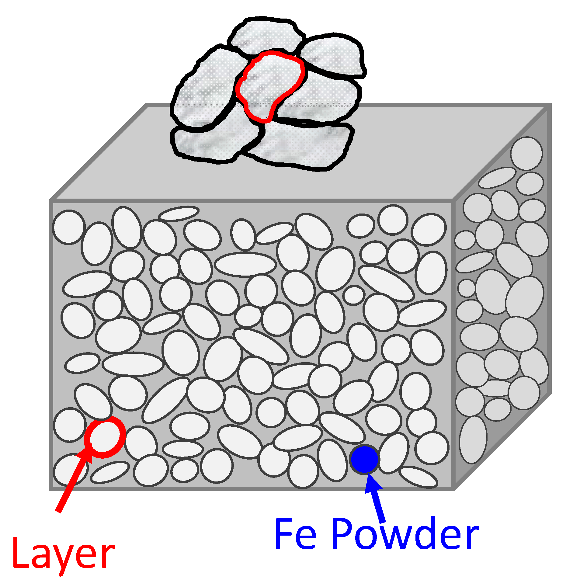
The main advantages of laminated steel concern the reduction in eddy current losses and, consequently, minor iron losses at medium-high frequencies. In Figure 1, the typical texture of SMC materials is shown: the eddy currents are only restricted to particle dimensions. SMC materials have some drawbacks, mainly related to mechanical strength. Nevertheless, the promising use of SMC materials in several applications [34,35,36] necessitates a detailed and fast characterization.

Figure 1.
Typical texture of SMC materials: ferromagnetic particles covered with an insulating layer.
In the present work, the simultaneous characterization of both coercivity and resistivity was proposed as a rapid preliminary selection before the SST test. Characterizations were performed after SMC production using different insulating layers and through different production process parameters, demonstrating that the electrical resistivity and coercivity may be considered to have faster information during the specimen’s production processes.
2. Problem Statement and Methods
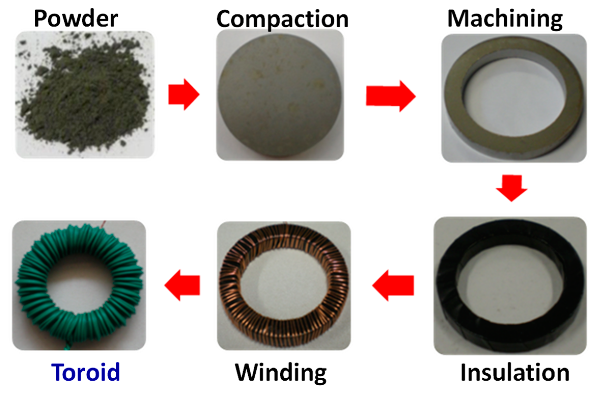
The primary magnetic test used for SMC materials is the toroidal magnetic test. Such a test is defined in the standards IEC 60404-6 and IEC 60404-4, and the characterization is performed with the well-known “transformer approach”, where two windings are wound around the toroidal magnetic core. The first winding provides the magnetization to the magnetic core with a current proportional to the magnetic field H; the second winding, prepared with a very thin copper wire accurately wrapped very close to the magnetic core, is adopted to detect the induced voltage, proportional to the magnetic flux density B. This test method requires a lot of time to prepare the specimens, mainly due to the mechanical machining and winding process. From this viewpoint, with the laboratory facilities, the production of the single toroidal sample takes around 3–4 h. The preparation of SMC toroidal samples for the toroidal magnetic test is described in Figure 2, where all production steps are shown in chronological order. The toroidal magnetic test is a complete and accurate measured method; on the other hand, the lengthy procedure for its preparation is the main drawback for extensive research activity and quick verification of the magnets.
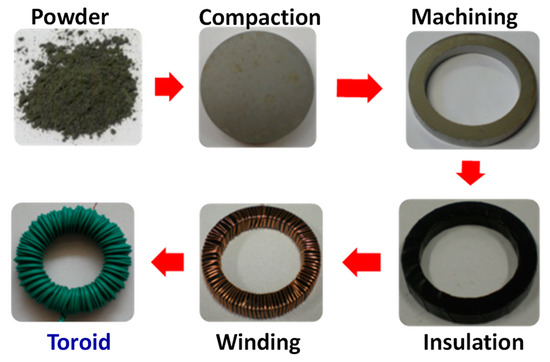
Figure 2.
Different procedures of the SMC preparation specimens for magnetic characterization through a toroidal magnetic test.
Furthermore, the use of toroidal-shaped specimens limits the types of analysis that may be conducted on the same specimen, such as mechanical tests.
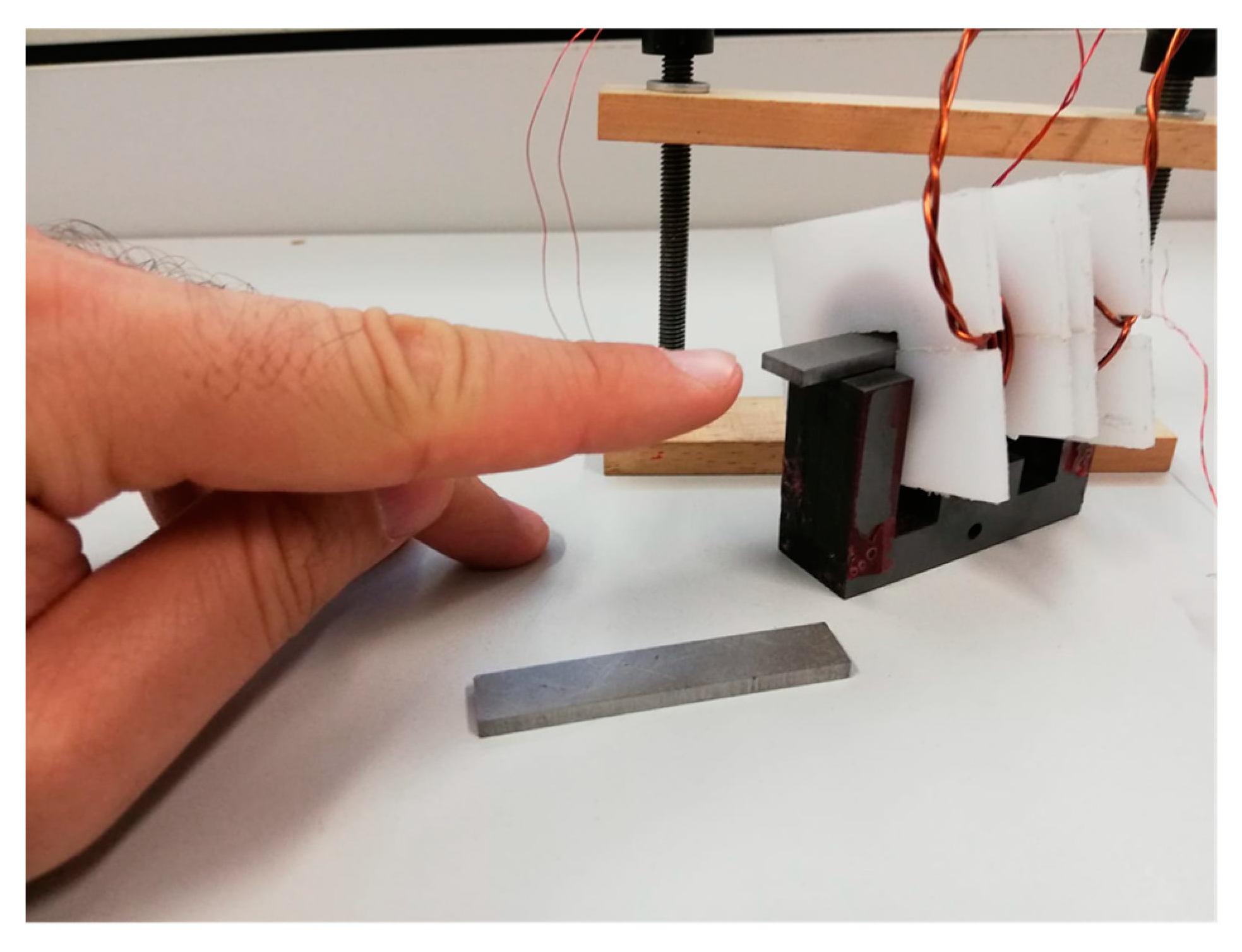
On the other hand, the magnetic characterization based on the single sheet tester (SST) method allows its application for laminated steel and SMC materials [37,38,39]. The parallelepiped samples (about 3 × 10 × 50 mm) can be easily prepared and arranged, as shown in Figure 3. Such samples do not require windings, and the measurements can be immediately performed, saving and optimizing the time of the specimen preparation process. In fact, parallelepiped samples are easily obtained after compression moulding without further machining processes. The single sheet tester is prepared with a secondary winding positioned around the middle of the sample and a split primary winding at both sides, as shown in Figure 4.

Figure 3.
The parallelepiped samples and their insertion in the SST device, not required to be wound and ready for the measurement.
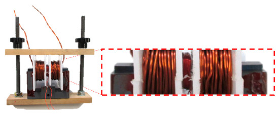
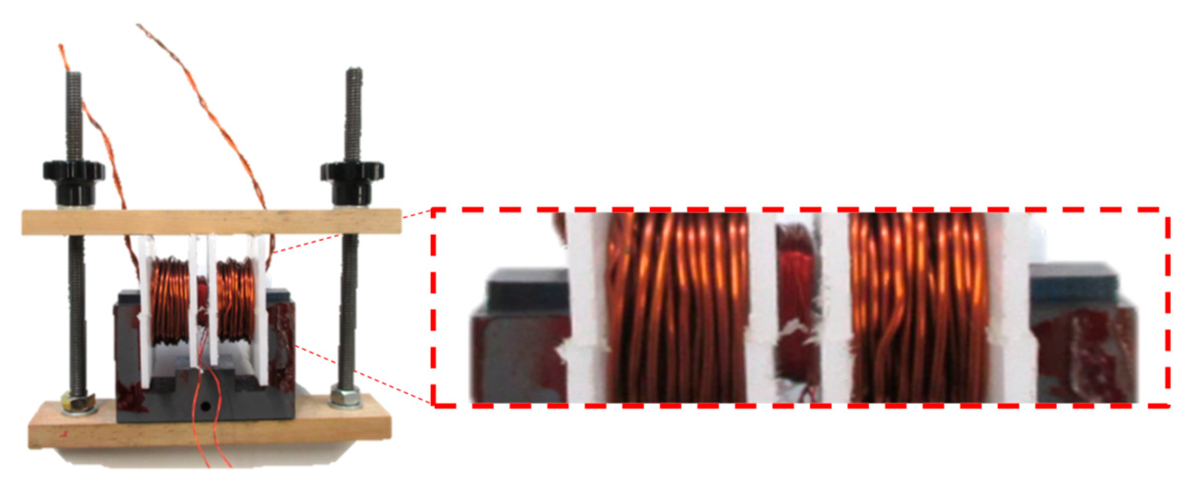
Figure 4.
SST method with the material under investigation with primary and secondary windings.
The used self-constructed SST joke follows a different design rule compared to most commercial ones. The primary winding is split into two equal parts, similar to a Helmholz coil, resulting in an upgraded uniformity in the middle zone. In that place, one can find the secondary winding, which is very limited in turn number and overall dimensions. The low number of turns allows measuring the higher frequency with the same hardware while preserving a good sensibility at the lower extreme of the spectrum. The short length helps select a volume portion where the field is more uniform, leaving the side artefacts and field deviations out.
The adaptation of a single shorting c-core is considered to be sufficient to avoid saturation of the core itself. This is due to the lower maximum relative permeability of the SMCs (500–600) compared to the laminated sheets. The used c-core is specifically designed for frequencies until 20 kHz to assure a good shorting path throughout the entire expected frequency range. As mentioned before, the field distribution at the sides of the specimen lies well outside the measuring volume coupled to the secondary coil, thus causing a very subtle or even no perturbation in the measured material properties, depending on the sample thickness.
The SST method has a faster application with respect to the toroidal magnetic test; however, it requires a preliminary calibration, made only once through a toroidal-shaped specimen, before starting.
The verified reliability of our SST method [20] allows performing quick tests for a primary selection of the considered materials, to be then subjected to an exhaustive characterization by the use of toroidal specimens.
However, many parameters are involved in SMC research. In this sense, a screening of specimens is necessary and may be performed in a very quick way, employing resistivity and coercivity tests, especially if a large number of specimens whose coating or production processes differ from each other.
The electrical resistivity is related to eddy current losses and depends on the layer typology and content. High resistivity values should correspond to low iron losses; simultaneously, the hysteresis losses can be increased for high layer thickness. Considering relations between iron losses, hysteresis and resistivity, coercivity and resistivity tests may be adopted before or instead of the SST, as the first step of SMCs analysis, to discard the non-compliant specimens.
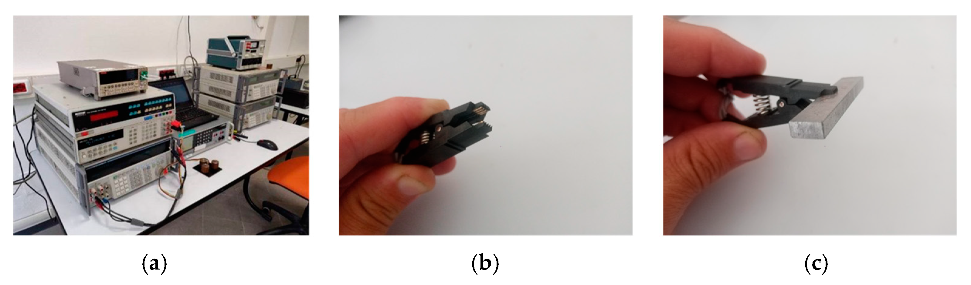
The accuracy required by the measurement of resistivity implies a dedicated system that has been arranged for the measurement of the same parallelepiped samples prepared for SST tests, as shown in Figure 5.

Figure 5.
The measurement system used to obtain the resistivity value: adopted devices (a), and prepared test clamp (b) and sample measurement (c).
The electrical resistivity values were found indirectly through the measurement of the electrical resistance, whose relationship is given by the following formula:
where R is the resistance, S is the surface and l in the denominator is the distance between the electrodes. A multimeter (Keithley) connected to a test clamp with a programming circuit has been used to obtain the resistance measurements. The method applied is based on DC current and four-terminal measurement. The clamp was used instead of the usual “probes or test leads” to obtain a more accurate result by limiting the variables due to the positioning and inclination of the tips on the samples.
For each SMC material sample, five resistance measurements have been taken by slightly changing the position of the clamp with each measure and then the average value has been calculated.
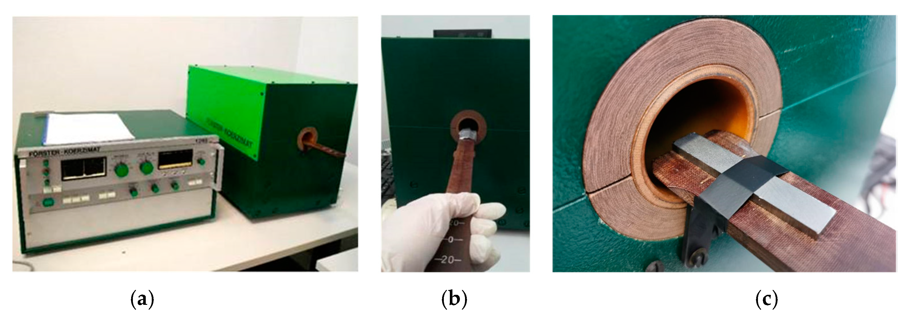
The coercivity values are associated with the hysteresis losses: by reducing such parameters, the iron losses decrease too. Additionally, the high coercivity can be linked with poor magnetic permeability. The measurement has been achieved using the coercimeter, which detects the coercivity value applying a static magnetic field. The method and measure, quick and very simple, are shown in Figure 6.

Figure 6.
Coercivity measurement at static field: coercimeter (a) and sample under test (b,c).
In summary, concerning the energetic aspects, the perfect SMC materials should have low coercivity (less than 500 A/m) and high electrical resistivity (up to 100 µΩm). This combination is not always easy to achieve; therefore, compromising solutions are assumed. Only specimens that were compliant with the required values of coercivity and resistivity are considered suitable for further characterization in SST and, if particularly well-performing in terms of iron losses and permeability, further characterized through mechanical tests.
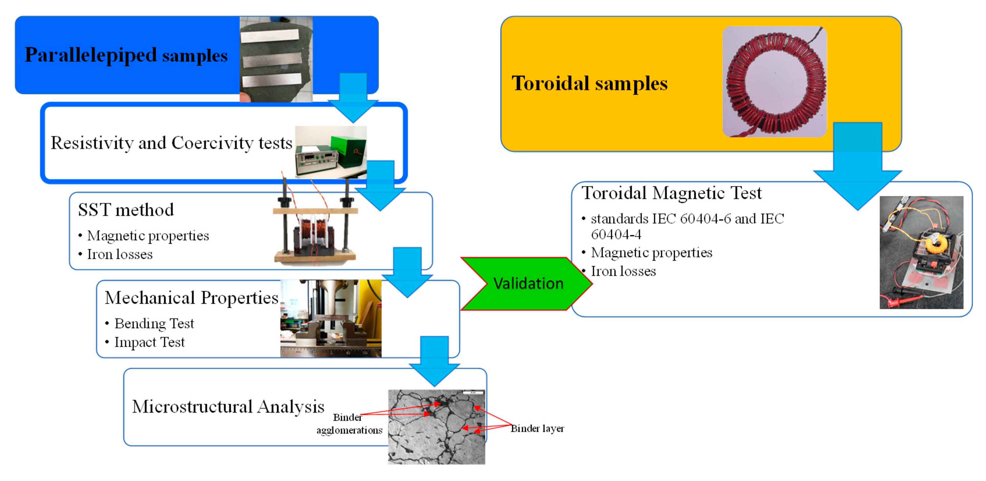
For a clearer and more detailed understanding, the two procedures are compared in Figure 7, starting from two different types of samples. Mainly, parallelepiped specimens are suitable for several tests without any sample preparation or machining. Conversely, the toroid samples cannot provide mechanical results or coercivity values in a static magnetic field. However, after the material selection utilizing the parallelepiped specimens, the toroidal sample must be used to validate the magnetic measures. So, with the proposed procedure, a single specimen (i.e., a single moulding process) leads to performing different measures.

Figure 7.
Two procedures based on types of samples. Parallelepiped samples facilitate a wide characterization with respect to toroidal magnetic tests. Resistivity and coercivity tests are the preliminary phases for SMCs characterizations.
In this work, different specimens were tested in terms of coercivity and resistivity as a function of different parameters, such as types of the insulating layer, weight percentage of the insulating layer, compacting pressure level, heat treatment environment and temperature, and coating process typologies.
3. Materials and Specimen Preparation
Some different insulating layers have been selected to analyse resistivity and coercivity. The first ones are organic layers: epoxy resin and novolac phenolic resin. The compacting level pressure for both the SMCs with polymeric layers is from 400 to 900 MPa with steps of 100 MPa, while the curing treatment for both resins is 150 °C for 30 min. Furthermore, the impact of polymeric binder weight percentage on SMCs has been evaluated. Binder weight percentage varies from 0.05 to 0.75 wt%. The effect of some coating process technologies has been examined too: turbula mixing and ball milling.
For the SMCs with the inorganic layer, the coating with nano-ferrite particles has been analysed. In this case, the adopted pressure was 800 MPa, the layer weight percentage was 0.2 wt%, and finally, the coating process technology was turbula mixing. The tested heat treatment temperatures are 400, 500 and 600 °C in different environments, vacuum, air and water vapour, respectively.
4. Experimental Results
4.1. Resistivity: Organic Layer
The pressure level increment has a high impact on the magnetic and mechanical properties of the SMCs. On the other hand, pressure level slightly affects the electrical resistivity values.
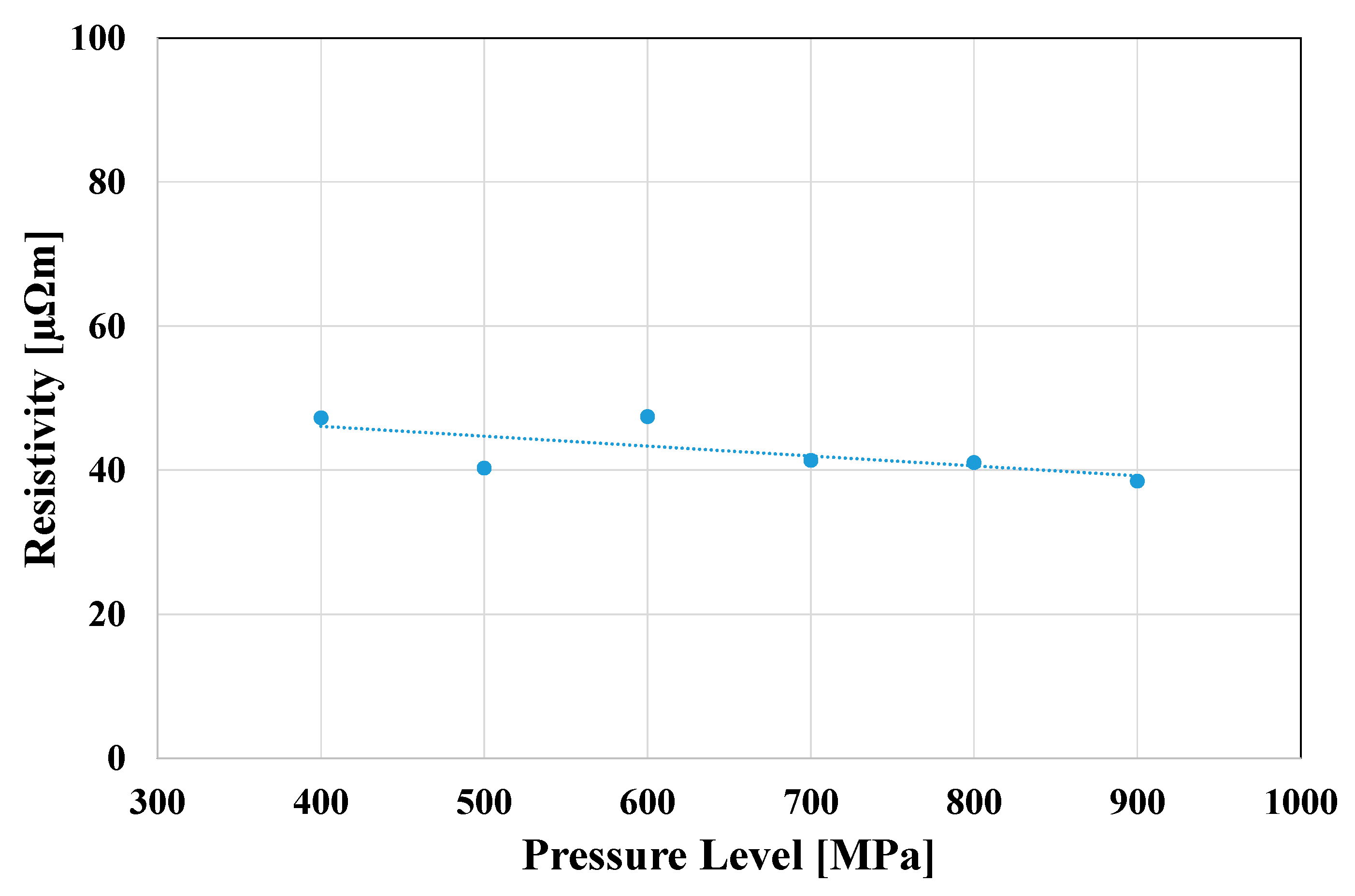
In Figure 8, the resistivity behaviour for the SMCs with epoxy resin at 0.2 wt% was shown. The higher decrease was noticed from 400 MPa to 500 MPa (−17% in resistivity), while from 400 MPa to 900 MPa, the resistivity decreases by 23%. These results highlight that the increase in pressure up to 900 MPa causes only a slight decrease in resistivity because the higher resistivity loss already occurs for lower pressures (up to 500 MPa). The maximum resistivity value is noticed for 400 MPa (47.26 µΩm), while an anomalous value was measured for 600 MPa, although the measure was repeated. This behaviour may be due to a possible different microstructural arrangement of the insulating layer in the middle of the sample that causes an increase in the average resistivity. Furthermore, in this context, such resistivity variations did not affect the quality of the SMCs; only a reduction in about one or more orders of magnitude can be considered detrimental.
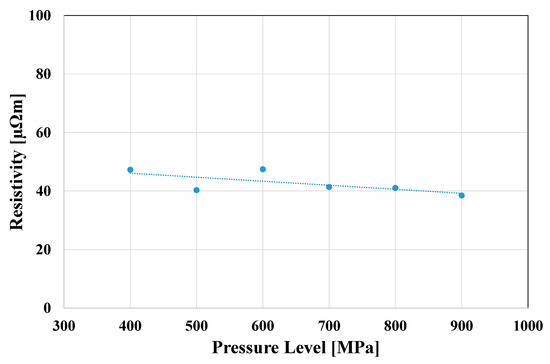
Figure 8.
Resistivity variations in SMCs with epoxy resin 0.2 wt% for different pressure levels.
Despite at 400 MPa the resistivity was higher, the literature demonstrated that specimens resulted in poor mechanical properties at similar compacting pressures. Moreover, the resistivity was almost constant from 700 MPa to 900 MPa. Considering these results, a compacting pressure of 800 MPa may be a good compromise between mechanical properties and resistivity values. Additionally, the industrial compaction does not exceed such values (about 800 MPa).
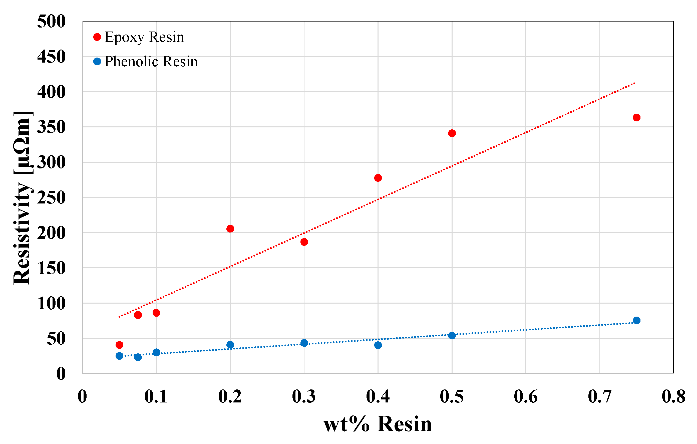
Figure 9 shows the resistivity as a function of wt% of resins at 800 MPa. In particular, with the increase in epoxy resin content, the resistivity has a slight increase; on the other hand, the same increment in phenolic resin content causes a significant increase in the measured resistivity. For each resin, the maximum values have been obtained for 0.75 wt%: 75.5 µΩm for epoxy resin and 363.1 µΩm for phenolic resin. Already from 0.075 wt% of resin content, phenolic resin results in better behaviour in terms of electrical resistivity (83.1 µΩm). Finally, the phenolic resin showed a higher variance with respect to the epoxy resin SMCs. This phenomenon is due to the loading of the powder in the mould during the compacting process: the SMCs with phenolic resin resulted in being easily dispersible.
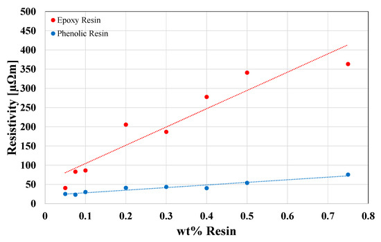
Figure 9.
Resistivity variations in SMCs with different percentages of epoxy and phenolic resins (wt%) at the same pressure level 800 MPa. (wt% shown: 0.05; 0.075; 0.1; 0.2; 0.3; 0.4; 0.5 and 0.75).
As the resistivity changes slightly with the epoxy resin content, 0.2 wt% of resin may be considered a good compromise between magnetic and mechanical properties. From the comparison between Figure 8 and Figure 9, it appears evident that for epoxy resins, resistivity is directly proportional to the resin content (as expected for the addition of insulating material) and inversely proportional to the increase in compaction pressure.
Figure 10 shows the variation in resistivity for SMCs with phenolic resins at 0.2 wt% and 800 MPa as a function of the adopted technology processes for performing the insulating coating. With equal process parameters, turbula mixing resulted in the lower resistivity value (almost 200 µΩm). Regarding ball milling, a significant increase from 24 h to 48 h in resistivity was noticed: 303 µΩm and 500 µΩm, respectively. These behaviours were due to the final ferromagnetic particle shape obtained. After turbula mixing, the SMC particles resulted in an irregular spongy shape, while after ball milling, the particles’ shape resulted in a plated-like shape, and this behaviour increased with the increase in the processing time. These plate-shaped particles resulted in less thickness with respect to the spongy irregular shape, causing the increase in the measured resistivity.
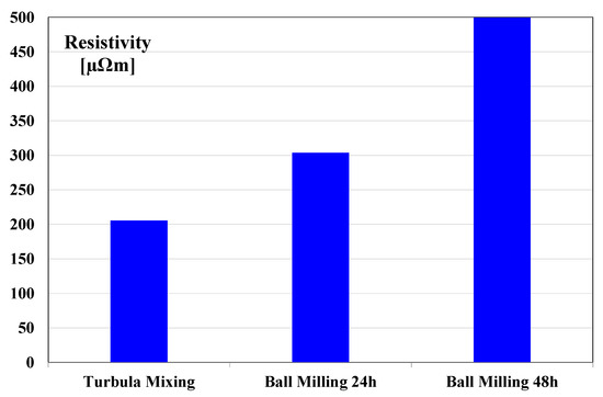
Figure 10.
Resistivity variations in SMCs with phenolic resins (0.2 wt% and 800 MPa) for different technological processes.
4.2. Resistivity: Inorganic Layer
The resistivity in SMCs coated by nano-ferrites was studied in the green state and after heat treatment at 400 °C, 500 °C and 600 °C in different environments (vacuum, air and steam). Specimens have 0.2 wt% of the nano-ferrites insulating layer and were compacted at 800 MPa. Compacting pressure of 800 MPa, as highlighted in the previous paragraph, ensures a good balance between resistivity and mechanical properties; this is always true because the reduction in resistivity with the increase in compacting pressure has the same magnitude.
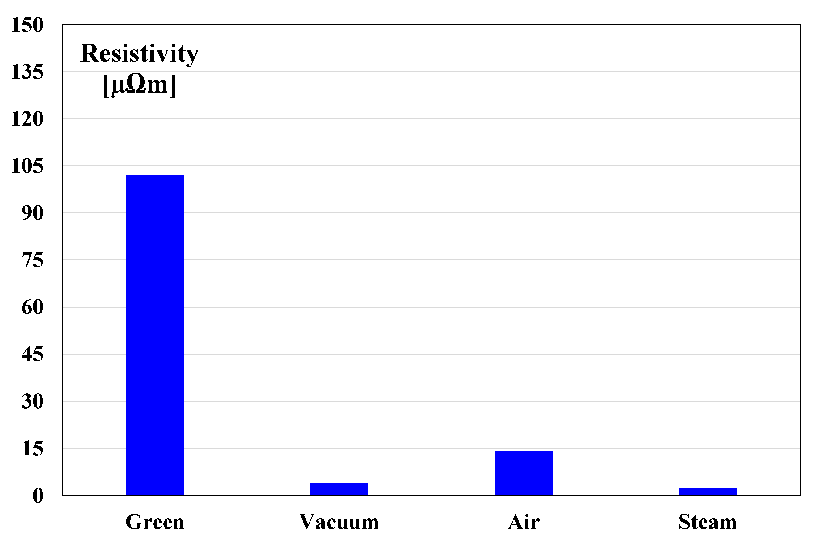
Figure 11 shows the resistivity of SMCs coated with nano-ferrites (0.2 wt% and 800 MPa) in the green state and after heat treatment at 400 °C at different environmental conditions. As attended, the resistivity in the green sample resulted in the higher value (102 µΩm); despite that, the heat treatment must be performed to increase the mechanical properties. Furthermore, stress relieving causes a beneficial effect on magnetic properties (coercivity and permeability). For this reason, a heat treatment at 400 °C was performed for a limited time of 15 min. Adopting the air environment obtained the best result (14.2 µΩm), while the steam usage resulted in the lower result (2.2 µΩm). In general, the high decrease in the resistivity for the green specimen values was due to the layer fracture during the stress relieving. Vacuum and steam environments cause less oxidation with respect to the air treatment, reducing the final resistivity of the sample.

Figure 11.
Comparison of resistivity between SMCs coated with nano-ferrites (0.2 wt% and 800 MPa): green and heat-treated SMCs as a function of the variations in heat treatment environments (400 °C 15 min).
In Figure 12, the effect of temperature on resistivity was reported. The heat treatments in air, steam and vacuum were performed at 400 °C, 500 °C and 600 °C. As a result, the air environment remains the best choice in respect to steam and vacuum. On the other hand, it appears evident that higher temperatures negatively affect resistivity, especially in steam and vacuum environments. In the air environment, resistivity decreases from 400 °C to 500 °C and then increase from 500 °C and 600 °C. This behaviour is probably associated with the oxidation and diffusion processes.
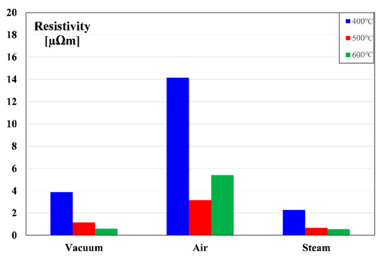
Figure 12.
Comparison of resistivity between SMCs coated with nano-ferrites (0.2 wt% and 800 MPa): for different heat treatments temperatures and environments.
4.3. Coercivity: Organic Layer
The coercivity measured in SMCs with organic layers (0.2 wt% and 800 MPa, prepared by Turbula mixing) is shown in Figure 13. Epoxy-coated SMCs resulted in a better coercivity; in fact, it resulted in almost 380 A/m in respect to the coercivity measured in the phenolic SMCs of nearly 419 A/m. The high coercivity supplants the excellent response in terms of resistivity for the phenolic resin coating, which is a negative behaviour. This phenomenon was probably caused by the thinner coating realized with the epoxy resin with respect to the phenolic resin layer. This hypothesis is corroborated by the minor resistivity measured for SMCs with epoxy resin layer (41 µΩm).
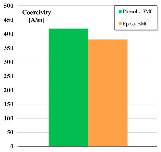
Figure 13.
Coercivity values in SMCs with phenolic and epoxy layers prepared by turbula mixing (0.2 wt% and 800 MPa).
Although ball milling after 24 h or 48 h gave the best resistivity results, turbola mixing-coated specimens were selected for further measures. This selection was due because specimens after turbola mixing maintain appreciable resistivity even after a quicker coating process and, industrially, short processes are preferable because of cost savings.
4.4. Coercivity: Inorganic Layer
Regarding the inorganic layer, Figure 14 shows the coercivity values in green and heat-treated SMCs. After heat treatment in steam, the obtained coercivity (417 A/m) was similar to the coercivity of the green specimen (424 A/m). Conversely, the best result was reached in the vacuum environment: 327 A/m.
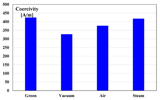
Figure 14.
Coercivity values in SMCs with nano-ferrites layers (0.2 wt% and 800 MPa) in green state and after heat treatment in different environments (400 °C 15 min).
In Figure 15, the effect of the temperature was investigated. In the steam environment, the coercivity slightly decreases from 400 °C to 500 °C, remaining almost constant with respect to the green state. Instead, at 600 °C, the coercivity in the steam environment is strongly reduced by 32% with respect to the value at 500 °C. On the other hand, for all the other environments, the coercivity strongly decreases at regular steps (−30% for vacuum and −15% air) with increasing temperature. The best value has been obtained for vacuum treatment at 600 °C (194.5 A/m).
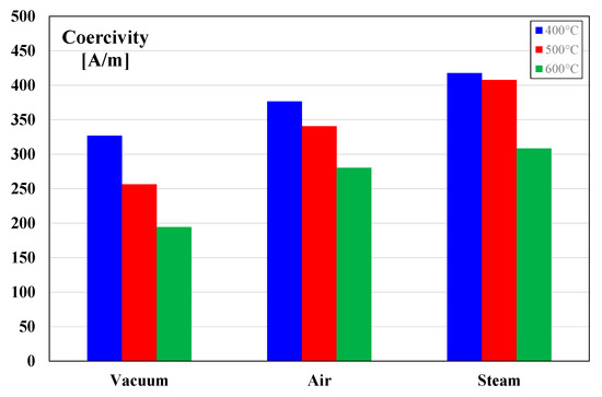
Figure 15.
Coercivity values in SMCs with nano-ferrites layers (0.2 wt% and 800 MPa) for different heat treatments temperatures and environments.
4.5. Comparison between SST and Toroidal Magnetic Test Methods
As the comparison between the SST parallelepiped sample and toroidal magnetic tests, specific iron losses and magnetic permeability have been considered at different frequencies. Two SMC materials have been selected based on previous experimental tests (Section 4.1, Section 4.2, Section 4.3, Section 4.4). Figure 16 shows the comparisons between the SST method and toroidal magnetic test methods.
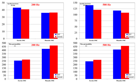
Figure 16.
Comparisons between SST method and toroidal magnetic test methods: specific iron losses and magnetic permeability for 200 Hz and 500 Hz.
The phenolic SMC with 0.2 wt% of resin content was chosen for high resistivity values. After the parallelepiped-shaped sample characterization, a toroidal-shaped sample was prepared to adopt the same production process (0.2 wt% of resin, 800 MPa). In the case of specific iron losses, the differences are 1% for 200 Hz and 8% at 500 Hz. Instead, the differences are about 12% for magnetic permeability for both frequencies.
The selected material for the low coercivity is ferrite SMC, treated in a vacuum atmosphere at 600 °C and compacted at 800 MPa with 0.2 wt% of ferrite content. The comparison shows a slight overestimation of 5% and 14% of the specific iron losses for 200 Hz and 500 Hz, respectively. On the other hand, the differences remain almost constant for the magnetic permeability: 6% and 8%, respectively.
The SST method shows constant differences for magnetic permeability values in the proposed frequencies range, while for specific iron losses, the differences were limited at low frequencies and incremented with the increase in the frequency.
5. Conclusions
The traditional toroidal magnetic test is the main standard for SMC materials but requires a long time due to the manufacturing and winding process. The single sheet tester turns out to be the faster method compared to toroidal magnetic tests; nonetheless, it always requires calibration through a standard procedure.
However, many types of insulating layers and variables may affect the SMC materials concerning the research activity. In this context, a preliminary selection and screening based on faster and simpler test methods can be helpful to develop and understand the SMC materials. The proposed preliminary tests measure electrical resistivity and coercivity that may be conducted before and eventually instead of the SST method. In fact, if the coercivity is too high or if the resistivity is too low, the SST measures can be avoided by cataloguing the specimens as non-compliant. In this sense, for SMCs, the constraints for resistivity and coercivity values can be introduced. It would be opportune that electrical resistivity is about or higher than 100 µΩm, and instead, the coercivity should be limited to values under 500 A/m. Furthermore, the SST method was compared with the toroidal magnetic test highlighting a slight overestimation of the specific iron losses and an underestimation of the magnetic permeability.
This work proved that choosing and guessing more appropriate SMC material development is possible using two simple preliminary tests before conducting SST tests. In this regard, considering the experimental results and the constraints proposed, it is possible to assume that SMCs with 0.2 wt% of phenolic resin, compacted at 800 MPa, and prepared by ball milling 48 h may be a good SMC with the organic layer. On the other hand, the SMC with 0.2 wt% of epoxy resin compacted at 800 MPa has the lowest coercivity value.
Additionally, the SMC with inorganic layer coated by 0.2 wt% of nano-ferrites shows the best coercivity values specifically for vacuum treatment at 600 °C. However, the resistivity for proposed SMCs with inorganic layers is unsatisfactory at such a higher thermal treatment.
Further detailed tests will be conducted to validate the selection of the material. Therefore, further tests will be performed to study other coating processes and parameter effects, and such activities will be followed by microstructural and compositional analysis (SEM-EDS analysis).
Author Contributions
Conceptualization, E.P., L.F. and M.A.G.; methodology, E.P. and F.F.; software, F.F.; validation, E.P., F.F. and L.F.; formal analysis, E.P., F.F. and F.C.; investigation, E.P., F.F. and F.C.; resources, L.F., F.C. and M.A.G.; data curation, E.P. and F.F.; writing—original draft preparation, E.P. and F.F.; writing—review and editing, L.F. and M.A.G.; visualization, F.C.; supervision, L.F., F.C. and M.A.G. All authors have read and agreed to the published version of the manuscript.
Funding
This research received no external funding.
Institutional Review Board Statement
Not applicable.
Informed Consent Statement
Not applicable.
Data Availability Statement
Not applicable.
Conflicts of Interest
The authors declare no conflict of interest.
References
- Fernando, N.; Hanin, F. Magnetic Materials for Electrical Machine Design and Future Research Directions: A review. In Proceedings of the 2017 IEEE International Electric Machines and Drives Conference, Miami, FL, USA, 21–24 May 2017; pp. 1–6. [Google Scholar] [CrossRef]
- Krings, A.; Boglietti, A.; Cavagnino, A.; Sprague, S. Soft magnetic material status and trends in electric machines. IEEE Trans. Ind. Electron. 2017, 64, 2405–2414. [Google Scholar] [CrossRef]
- Ferraris, L.; Pošković, E.; Franchini, F.; Actis Grande, M.; Bianchi, N. New Magnetic Materials in the Electrical Machines: Development and Applications. In Proceedings of the EPMA Europe’s Annual Powder Metallurgy Congress and Exhibition 2017, Milan, Italy, 1–5 October 2017. [Google Scholar]
- Kącki, M.; Rylko, M.S.; Hayes, J.G.; Sullivan, C.R. Magnetic material selection for EMI filters. In Proceedings of the IEEE Energy Conversion Congress and Exposition Conference, Cincinnati, OH, USA, 1–5 October 2017; pp. 2350–2356. [Google Scholar] [CrossRef]
- Leary, A.M.; Ohodnicki, P.R.; McHenry, M.E. Soft Magnetic Materials in High-Frequency, High-Power Conversion Applications. JOM 2012, 64, 772–781. [Google Scholar] [CrossRef]
- Schoppa, A.; Delarbre, P. Soft magnetic powder composites and potential applications in modern electric machines and devices. IEEE Trans. Magn. 2014, 50, 1613–1616. [Google Scholar] [CrossRef]
- Périgo, E.A.; Weidenfeller, B.; Kollár, P.; Füzer, J. Past, present and future of soft magnetic composites. AIP Appl. Phys. Rev. 2018, 5, 031301. [Google Scholar] [CrossRef]
- Sunday, K.J.; Taheri, M.L. Soft magnetic composites: Recent advancements in the technology. Met. Powder Rep. 2017, 72, 425–429. [Google Scholar] [CrossRef]
- Hultman, L.; Andersson, O. Advances in SMC Technology—Materials and Applications. In Proceedings of the EPMA Europe’s annual Powder Metallurgy Congress and Exhibition 2009, Copenhagen, Denmark, 13 October 2009. [Google Scholar]
- Bureš, R.; Strečkova, M.; Faberova, M.; Kollar, P.; Fuzer, J. Advances in powder metallurgy soft magnetic composite materials. Arch. Metall. Mater. 2017, 62, 1149–1154. [Google Scholar] [CrossRef] [Green Version]
- Wu, Z.Y.; Jiang, Z.; Fan, X.A.; Zhou, L.J.; Wang, W.L.; Xu, K. Facile synthesis of Fe-6.5wt%Si/SiO2 soft magnetic composites as an efficient soft magnetic composite material at medium and high frequencies. J. Alloys Compd. 2018, 742, 90–98. [Google Scholar] [CrossRef]
- Wu, Z.; Fan, X.; Wang, J.; Li, G.; Gan, Z.; Zhang, Z. Core loss reduction in Fe–6.5wt.%Si/SiO2 core–shell composites by ball milling coating and spark plasma sintering. J. Alloys Compd. 2014, 617, 21–28. [Google Scholar] [CrossRef]
- Sunday, K.J.; Hanejko, F.G.; Taheri, M.L. Magnetic and microstructural properties of Fe3O4-coated Fe powder soft magnetic composites. J. Magn. Magn. Mater. 2017, 423, 164–170. [Google Scholar] [CrossRef]
- Peng, Y.; Yi, Y.; Li, L.; Ai, H.; Wang, X.; Chen, L. Fe-based soft magnetic composites coated with NiZn ferrite prepared by a co-precipitation method. J. Magn. Magn. Mater. 2017, 428, 148–153. [Google Scholar] [CrossRef]
- Zhao, G.; Wu, C.; Yan, M. Enhanced magnetic properties of Fe soft magnetic composites by surface oxidation. J. Magn. Magn. Mater. 2016, 399, 51–57. [Google Scholar] [CrossRef]
- Yaghtin, M.; Hossein Taghvaei, A.; Hashemi, B.; Janghorban, K. Effect of heat treatment on magnetic properties of iron-based soft magnetic composites with Al2O3 insulation coating produced by sol–gel method. J. Alloys Compd. 2013, 581, 293–297. [Google Scholar] [CrossRef]
- Luo, F.; Fan, X.; Luo, Z.; Hu, W.; Wang, J.; Wu, Z.; Li, G.; Li, Y.; Liu, X. Preparation and magnetic properties of FeSiAl-based soft magnetic composites with MnO/Al2O3 insulation layer. J. Magn. Magn. Mater. 2020, 498, 166084. [Google Scholar] [CrossRef]
- Zhou, B.; Dong, Y.; Liu, L.; Chang, L.; Bi, F.; Wang, X. Enhanced soft magnetic properties of the Fe-based amorphous powder cores with novel TiO2 insulation coating layer. J. Magn. Magn. Mater. 2019, 474, 1–8. [Google Scholar] [CrossRef]
- Zheng, J.; Zheng, H.; Lei, J.; Qiao, L.; Ying, Y.; Cai, W.; Li, W.; Yu, J.; Liu, Y.; Huang, X.; et al. Structure and magnetic properties of Fe-based soft magnetic composites with an Li–Al–O insulation layer obtained by hydrothermal synthesis. J. Alloys Compd. 2020, 816, 152617. [Google Scholar] [CrossRef]
- Poskovic, E.; Franchini, F.; Actis Grande, M.; Ferraris, L.; Bidulsky, R. Innovative Soft Magnetic Composite Materials: Evaluation of magnetic and mechanical properties. DE GRUYTER Open Eng. 2018, 8, 368–372. [Google Scholar] [CrossRef]
- Shokrollahi, H.; Janghorban, K. The effect of compaction parameters and particle size on magnetic properties of iron-based alloys used in soft magnetic composites. Mater. Sci. Eng. B 2006, 134, 41–43. [Google Scholar] [CrossRef]
- Gramatyka, P.; Nowosielski, R.; Sakiewicz, P.; Raszka, T. Soft magnetic composite based on nanocrystalline Fe73.5Cu1Nb3Si13.5B9 and Fe powders. J. Achiev. Mater. Manuf. Eng. 2006, 15, 27–31. [Google Scholar]
- Dias, M.M.; Mozetic, H.J.; Barboza, J.S.; Martins, R.M.; Pelegrini, L.; Schaeffer, L. Influence of resin type and content on electrical and magnetic properties of soft magnetic composites (SMCs). Powder Technol. 2013, 237, 213–220. [Google Scholar] [CrossRef]
- Ferraris, L.; Pošković, E.; Franchini, F. New soft magnetic composites for electromagnetic applications with improved mechanical properties. AIP Adv. 2016, 6, 056209. [Google Scholar] [CrossRef] [Green Version]
- Streckova, M.; Bures, R.; Faberova, M.; Medvecky, L.; Fuzer, J.; Kollar, P. A comparison of soft magnetic composites designed from different ferromagnetic powders and phenolic resins. Chin. J. Chem. Eng. 2015, 23, 736–743. [Google Scholar] [CrossRef]
- Taghvaei, A.H.; Shokrollahi, H.; Janghorban, K. Magnetic and structural properties of iron phosphate–phenolic soft magnetic composites. J. Magn. Magn. Mater. 2009, 321, 3926–3932. [Google Scholar] [CrossRef]
- Taghvaei, A.H.; Shokrollahi, H.; Ghaffari, M.; Janghorban, K. Influence of particle size and compaction pressure on the magnetic properties of iron-phenolic soft magnetic composites. J. Phys. Chem. Solids 2010, 71, 7–11. [Google Scholar] [CrossRef]
- Kollár, P.; Birčáková, Z.; Vojtek, V.; Füzer, J.; Bureš, R.; Fáberová, M. Dependence of demagnetizing fields in Fe-based composite materials on magnetic particle size and the resin content. J. Magn. Magn. Mater. 2015, 388, 76–81. [Google Scholar] [CrossRef]
- Luo, D.; Wu, C.; Yan, M. Incorporation of the Fe3O4 and SiO2 nanoparticles in epoxy-modified silicone resin as the coating for soft magnetic composites with enhanced performance. J. Magn. Magn. Mater. 2018, 452, 5–9. [Google Scholar] [CrossRef]
- Dobrzanski, L.A.; Nowosielski, R.; Konieczny, J.; Przybył, A.; Wysłocki, J. Structure and properties of nanocrystalline soft magnetic composite materials with silicon polymer matrix. J. Magn. Magn. Mater. 2005, 290–291, 1510–1512. [Google Scholar] [CrossRef]
- Birčáková, Z.; Füzer, J.; Kollár, P.; Streckova, M.; Szabó, J.; Bureš, R.; Fáberová, M. Magnetic properties of Fe-based soft magnetic composite with insulation coating by resin bonded Ni-Zn ferrite nanofibers. J. Magn. Magn. Mater. 2019, 485, 1–7. [Google Scholar] [CrossRef]
- Meng, B.; Yang, B.; Zhang, X.; Zhou, B.; Li, X.; Yu, R. Combinatorial surface coating and greatly-improved soft magnetic performance of Fe/Fe3O4/resin composites. Mater. Chem. Phys. 2020, 242, 122478. [Google Scholar] [CrossRef]
- Zhou, B.; Chi, Q.; Dong, Y.; Liu, L.; Zhang, Y.; Chang, L.; Pan, Y.; He, A.; Li, J.; Wang, X. Effects of annealing on the magnetic properties of Fe-based amorphous powder cores with inorganic-organic hybrid insulating layer. J. Magn. Magn. Mater. 2020, 494, 165827. [Google Scholar] [CrossRef]
- Pošković, E.; Ferraris, L.; Franchini, F.; Cavagnino, A.; Actis Grande, M. SMC Materials in Electrical Machine Prototypes. In Proceedings of the IEEE International Electric Machines and Drives Conference, San Diego, CA, USA, 12–15 May 2019; pp. 2042–2047. [Google Scholar] [CrossRef]
- Schoppa, A.; Delarbre, P.; Schatz, A. Optimal Use of soft magnetic powder composite (SMC) in Electric Machines. In Proceedings of the MPIF PowderMet International Conference on Powder Metallurgy & Particulate Materials, Chicago, IL, USA, 24–27 June 2013; pp. 10-130–10-139. [Google Scholar]
- Cros, J.; Perin, A.J.; Viarouge, P. Soft Magnetic Composites for Electromagnetic Components in Lighting Applications. In Proceedings of the IEEE Industry Applications Society Annual Meeting, Pittsburgh, PA, USA, 13–18 October 2002; pp. 342–347. [Google Scholar] [CrossRef]
- Appino, C.; Ferrara, E.; Fiorillo, F.; Rocchino, L.; Ragusa, C.; Sievert, J.; Belgrand, T.; Wang, C.; Denke, P.; Siebert, S.; et al. International comparison on SST and Epstein measurements in grain-oriented Fe-Si sheet steel. Int. J. Appl. Electromagn. Mech. 2015, 48, 123–133. [Google Scholar] [CrossRef] [Green Version]
- Miyagi, D.; Yamazaki, T.; Otome, D.; Nakano, M.; Takahashi, N. Development of Measurement System of Magnetic Properties at High Flux Density Using Novel Single-Sheet Tester. IEEE Trans. Magn. 2009, 45, 3889–3892. [Google Scholar] [CrossRef]
- Pošković, E.; Ferraris, L.; Franchini, F.; Bidulsky, R.; Actis Grande, M. Novel SMC Materials with the Insulating Layer Treated at High Temperature. In Proceedings of the EPMA Europe’s Annual Powder Metallurgy Congress and Exhibition 2019, Maastricht, The Netherlands, 13–16 October 2019. [Google Scholar]


Publisher’s Note: MDPI stays neutral with regard to jurisdictional claims in published maps and institutional affiliations. |
© 2021 by the authors. Licensee MDPI, Basel, Switzerland. This article is an open access article distributed under the terms and conditions of the Creative Commons Attribution (CC BY) license (https://creativecommons.org/licenses/by/4.0/).