Article

Real-Time Terrain-Following of an Autonomous Quadrotor by Multi-Sensor Fusion and Control

1
Key Laboratory of Micro-Inertial Instrument and Advanced Navigation Technology, Ministry of Education, School of Instrument Science and Engineering, Southeast University, Nanjing 210096, China
2
College of Command and Control Engineering, Army Engineering University, Nanjing 210007, China
*
Author to whom correspondence should be addressed.
Appl. Sci. 2021, 11(3), 1065; https://doi.org/10.3390/app11031065
Submission received: 10 December 2020 / Revised: 11 January 2021 / Accepted: 19 January 2021 / Published: 25 January 2021
(This article belongs to the Special Issue Intelligent Robotics and Mechatronics)

Abstract

:
For the application of the autonomous guidance of a quadrotor from confined undulant ground, terrain-following is the major issue for flying at a low altitude. This study has modified the open-source autopilot based on the integration of a multi-sensor receiver (a Global Navigation Satellite System (GNSS)), a Lidar-lite (a laser-range-finder device), a barometer and a low-cost inertial navigation system (INS)). These automatically control the position, attitude and height (a constant clearance above the ground) to allow terrain-following and avoid obstacles based on multi-sensors that maintain a constant height above flat ground or with obstacles. The INS/Lidar-lite integration is applied for the attitude and the height stabilization, respectively. The height control is made by the combination of an extended Kalman filter (EKF) estimator and a cascade proportional-integral-derivative (PID) controller that is designed appropriately for the noise characteristics of low accuracy sensors. The proposed terrain-following is tested by both simulations and real-world experiments. The results indicate that the quadrotor can continuously navigate and avoid obstacles at a real-time response of reliable height control with the adjustment time of the cascade PID controller improving over 50% than that of the PID controller.

1. Introduction

In recent years, advances in constructions, electronics, sensors and control algorithms have fueled a growth in the development of unmanned aerial vehicles (UAVs) [1]. The automatic applications of UAVs rely on the continuous control of the position, attitude, speed and other high level commands [2,3]. Specifically, the attitude and height (the clearance from the ground) controllers allow terrain-following of an autonomous quadrotor, which is useful for topography prediction, navigation and obstacle avoidance [4,5,6]. An integrated navigation framework is an autonomous system used for determining the position, attitude and velocity of UAVs using multi-sensors [7,8], i.e., a global positioning system (GPS), an inertial measurement unit ((IMU) e.g., an accelerometer, a gyroscope and a magnetometer) [9] and radar or distance sensors [10,11,12,13]. To achieve a more reliable travel in real environments, fruitful research efforts have focused on the height control problem [14].
The height control of common UAVs applies a proportional-integral-derivative (PID) control structure for the altitude that handles high impact and changed mass [15,16,17]. These controllers compare the behavior of the UAVs with a model and adapt the output of the controller to minimize the error between the model and the system. The design, implementation, simulation and evaluation of this controller will be presented in this paper divided into algorithms based on a classic control theory and a modern control theory. Control algorithms based on a modern control theory include a dynamic inverse control [18], a linear-quadratic regulator (LQR) control [19], an intelligent control (such as a neural network control [20,21]) and an adaptive control [22,23]. Ngo used the dynamic inversion based adaptive control method to control the height of the UAVs in the climbing stage and verified that the method had good effects through simulation [24]. However, the long-term flight of UAVs is a time-varying nonlinear system [25,26] whose external environment, speed, load and other parameters change continuously. For dynamic inverse control strategies, the control effect is often not satisfactory because there is no effective method to obtain the precise parameters of the model. Due to the requirement of the rapidity of response, the intelligent control algorithm, which needs complex calculations, is less used in practical engineering applications though it has a strong environmental adaptability [16]. Thus, in engineering practice, methods based on a classic control (such as the PID control) are mostly used because of the uncertainty of system parameters and the requirement of real-time control. The PID control is an effective and reliable flight control strategy that has been studied for some time and has a mature design strategy. For the UAVs’ terrain-following system, the problem to be solved is that the traditional single-stage PID control cannot meet the requirements in terms of response speed and stability [27]. In order to improve the quality of control, Idres used the cascade PID control method to control the UAVs and verified the efficiency of the cascade PID controlled UAVs in tracking slopes, circles and sinusoidal trajectories through a simulation [28]. Ren analyzed the system based on the classical control theory and proved that the cascade PID was better than the traditional single-stage PID control from an amplitude margin and a phase angle margin [29]. A cascade PID is one of the effective methods used to improve the quality of traditional PID control and it has been widely used in the field of process control [30,31,32]. For the cascade PID control of terrain-following UAVs, how to set the control feedback state quantity and how to adjust its parameters are important issues. The Ziegler–Nichols method [33], the critical proportionality method [34] and the attenuation curve method [35] are commonly used in engineering for tuning. Choosing a suitable method for PID tuning can also help improve the quality of control [36,37].
The main goal of this study is to improve the autonomous terrain-following and navigation performance of a quadrotor system. We address the detailed mathematical modeling of the quadrotor’s kinematics and dynamics of the quadrotor. The autonomous controller comprises of an integrated control for the quadrotor’s position, attitude and height control with the multi-sensor based control loops for terrain-following depicted in Figure 1. The control methodologies are conducted in MATLAB Simulink and the experiments on a quadrotor test-bed where interference such as wind conditions and sensor noise are incorporated in both the simulation and real-world experiments. A quadcopter measures its altitude relatively to the ground by using a range-finder. However, when the surface of the ground is fluctuating, a traditional PID control algorithm cannot meet the requirements of accurate terrain-following. Work in this innovation is the adaptive control function using the integration of a Global Navigation Satellite System (GNSS) (GPS) and a BeiDou Navigation Satellite System (BDS) [38], an inertial navigation system (INS) [39], a barometer [40] and a Lidar-lite sensor [41], especially the combination of an extended Kalman filter (EKF) and the cascade PID controller. In this paper, a dynamic model of the quadcopter is built and then linearized for simplification. The cascade PID is modeled and simulated in Simulink based on a tuning method according to the transfer function. Finally, an experiment is performed based on an open-source flight controller Pixhawk. Both the simulation and the real flight show improvements with this controller.
The rest of this paper is organized as follows. In II, dynamic models of the quadrotor are described. In III, we design the integration of the position and height control based on the combination of an extended Kalman filter and a cascade PID. IV verifies the reliability of the proposed models by MATLAB Simulink and real-world quadrotor flying avoiding a box above the ground. Conclusions are given in V.

2. Quadrotor System Models

2.1. Quadrotor Dynamic Models

The quadrotor changes its position and attitude by modifying the speed of the four motors [42,43]. The movements of back and forth and left and right are produced by pitch and roll, respectively, and the movements of up and down are achieved by the four motors increasing or decreasing the speed at the same time.
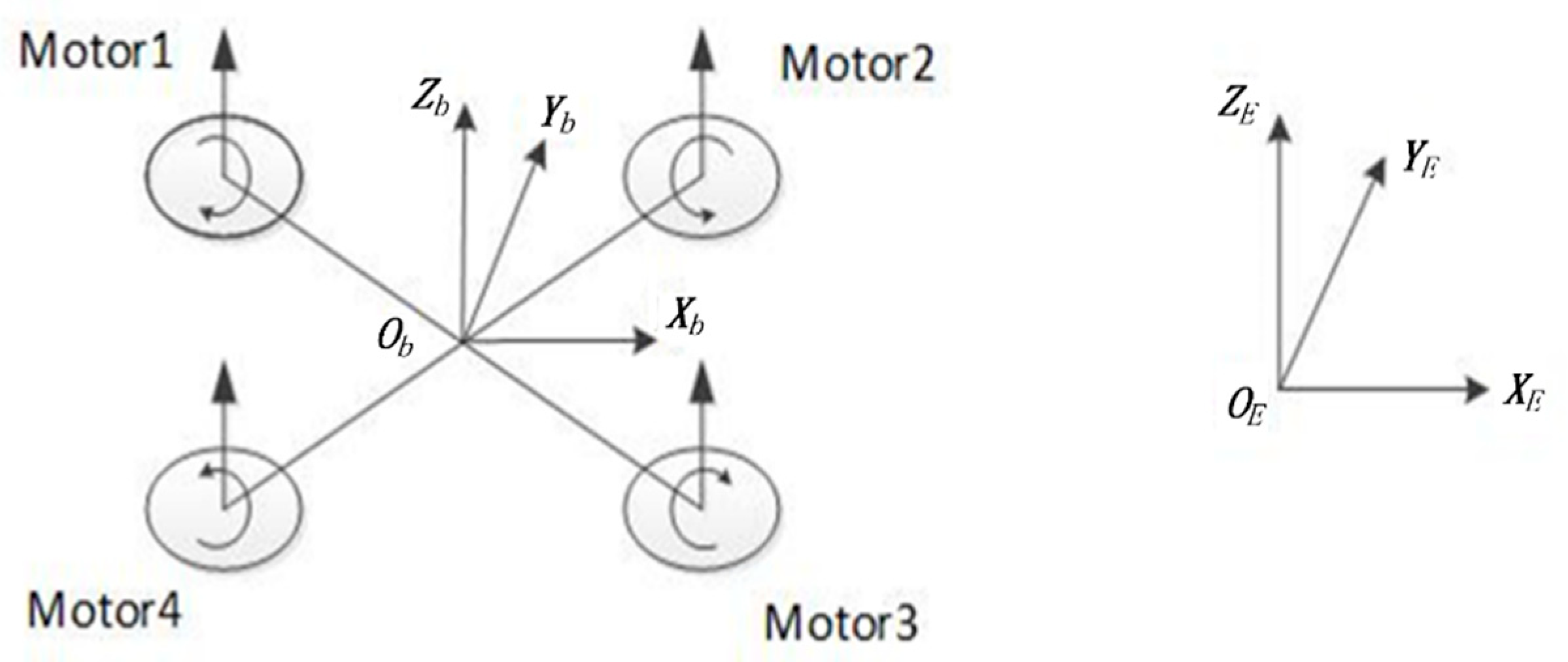
In order to study the kinematic law of aircraft, two coordinate systems [44] depicted in Figure 2 are defined as follows:
  • The geographic coordinate system ( O E X E Y E Z E ) is used to study the motion state of aircraft relative to the earth and the space position coordinates in which Y E - X E - Z E point to East-North-Up, respectively.
  • The airframe coordinate system ( O b X b Y b Z b ) is used to study the rotational motion of aircraft relative to the center of gravity in which Y b - X b - Z b point to Right-Front-Up, respectively.
According to the conversion relationship between the Euler angle and the attitude matrix, the attitude transfer matrix R E b from the geographic coordinate system to the airframe coordinate system can be obtained:
R E b = [ cos θ sin ψ sin ψ cos θ sin θ sin ϕ sin θ cos ψ cos ϕ sin ψ sin ϕ sin θ sin ψ + cos ϕ cos ψ sin ϕ cos θ cos ϕ sin θ cos ψ + sin ϕ sin ψ cos ϕ sin ψ sin θ sin ϕ cos ψ cos ϕ cos θ ]
The vector of [ x y z ϕ θ ψ ] T represents the position and angle of the quadrotor in the geographic coordinate system and the vector of [ u v w p q r ] T represents the linear velocity and angular velocity of the quadrotor in the airframe coordinate system. The conversion relationship of these twelve-dimensional variables in the two coordinate systems is:
{ v E = R b E v b ω = T ω b .
In Equation (2), v E = [ x ˙ y ˙ z ˙ ] T R 3 , ω = [ ϕ ˙ θ ˙ ψ ˙ ] T R 3 , v b = [ u v w   ] T R 3 , ω b = [ p q r   ] T R 3 , the R b E is the direction cosine matrix from the airframe coordinate system to the geographic coordinate system and T is the conversion matrix between the airframe rotation angular velocity and the attitude angle change rate. The dynamic model of the quadrotor is:
{ x ˙ = w ( sin ϕ sin ψ + cos ϕ cos ψ sin θ ) v ( cos ϕ sin ψ cos ψ sin ϕ ) y ˙ = v ( cos ϕ cos ψ + sin ϕ sin ψ sin θ ) w ( cos ψ sin ϕ cos ϕ sin ψ ) z ˙ = w ( cos ϕ cos θ ) u ( sin θ ) + v ( cos θ sin ϕ ) ϕ ˙ = p + r ( cos ϕ tan θ ) + q ( sin ϕ tan θ ) θ ˙ = q ( cos ϕ ) r ( sin ϕ ) ψ ˙ = r cos ϕ cos θ + q sin ϕ cos θ .
According to Newton’s law of motion, the total force acting on the quadrotor is:
m ( ω b v b + v ˙ b ) = f b ,
where m is the mass of the quadcopter, represents the cross product operation and f b = [ f x f y f z ] R 3 is the total force acting on the quadrotor. According to Euler’s equation, the total torque produced by the four motors is:
I ω ˙ b + ω b ( I ω b ) = m b .
In (5), τ b = [ τ x τ y τ z ] R 3 represents the total torque, I is the inertia matrix of the quadrotor, which can be simplified as follows according to the symmetry of the quadrotor:
I = [ I x x 0 0 0 I y y 0 0 0 I z z ] ,
where I x x ,   I y y ,   I z z are called the central principal moments of inertia and can be measured through experiments. Therefore, the dynamic model of the quadrotor in the airframe coordinate system is:
{ f x = m ( u ˙ + q w r v ) f y = m ( v ˙ p w + r u ) f z = m ( w ˙ + p v q u ) τ x = p ˙ I x x q r I y y + q r I z z τ y = q ˙ I y y + p r I x x p r I z z τ z = r ˙ I z z p q I x x + p q I y y .
The above equation is established under the condition that the origin and axis of the airframe coordinate system coincide with the centroid and main axis of the quadrotor.
The total external force received by the quadrotor in the airframe coordinate system is:
f b = m g R T e ^ z f t e ^ 3 + f w ,
where e ^ z is the unit vector of the z-axis of the geographic coordinate system, e ^ 3 is the unit vector of the z-axis of the airframe coordinate system, g is the acceleration of gravity, f t is the total pulling force generated by motors and f w is the force generated by the wind acting on the quadrotor.
Ignoring the rotational torque in the control equation, the total external torque Τ b in the airframe coordinate system can be expressed as:
Τ b = τ b + τ w ,
where τ b = [ τ x τ y τ z ] T R 3 , τ w = [ τ w x τ w y τ w z ] T R 3 are the control torques generated by the difference in motor speed and the movement generated by the wind acting on the quadrotor.
Substituting Equations (8) and (9) into Equation (7), the complete dynamic model of the quadrotor in the airframe coordinate system is obtained as:
{ m g ( sin θ ) + f w x = m ( u ˙ + q w r v ) m g ( cos θ sin ϕ ) + f w y = m ( v ˙ p w + r u ) m g ( cos θ cos ϕ ) + f w z f t = m ( w ˙ + p v q u ) τ x + τ w x = p ˙ I x x q r I y y + q r I z z τ y + τ w y = q ˙ I y y + p r I x x p r I z z τ z + τ w z = r ˙ I z z p q I x x + p q I y y
Considering that the force and torque input by the control system are proportional to the square of the motor speed, the parameters in (10) are as follows:
{ f t = c T ( Ω 1 2 + Ω 2 2 + Ω 3 2 + Ω 4 2 ) τ x = 2 2 c T l ( Ω 1 2 + Ω 2 2 + Ω 3 2 Ω 4 2 ) τ y = 2 2 c T l ( Ω 1 2 Ω 2 2 + Ω 3 2 + Ω 4 2 ) τ z = c M ( Ω 1 2 + Ω 2 2 Ω 3 2 + Ω 4 2 ) ,
where l is the distance between the center of the motor and the center of the airframe, c T is the tensile coefficient of the motor, and c M is the torque coefficient. All of the above parameters can be measured through experiments. Substituting (11) into (10), the complete dynamic model of the quadrotor in the airframe coordinate system can be further expressed as:
{ m ( u ˙ + q w r v ) = m g ( sin θ ) + f w x m ( v ˙ p w + r u ) = m g ( cos θ sin ϕ ) + f w y m ( w ˙ + p v q u ) = m g ( cos θ cos ϕ ) + f w z c T ( Ω 1 2 + Ω 2 2 + Ω 3 2 + Ω 4 2 ) p ˙ I x x q r I y y + q r I z z = 2 2 c T l ( Ω 1 2 + Ω 2 2 + Ω 3 2 Ω 4 2 ) + τ w x q ˙ I y y + p r I x x p r I z z = 2 2 c T l ( Ω 1 2 Ω 2 2 + Ω 3 2 + Ω 4 2 ) + τ w y r ˙ I z z p q I x x + p q I y y = c M ( Ω 1 2 + Ω 2 2 Ω 3 2 + Ω 4 2 ) + τ w z .
The parameter setting of the quadrotor models is listed in Table 1.
The state vector is expressed as follows:
x = [ ϕ θ ψ p q r u v w x y z ] T .
According to Equations (3) and (10), the dynamic equation of the quadrotor can be rewritten as:
{ ϕ ˙ = p + r ( cos ϕ tan θ ) + q ( sin ϕ tan θ ) θ ˙ = q ( cos ϕ ) r ( sin ϕ ) ψ ˙ = r cos ϕ cos θ + q sin ϕ cos θ p ˙ = I y y I z z I x x r q + τ x + τ w x I x x q ˙ = I z z I x x I y y p r + τ y + τ w y I y y r ˙ = I x x I y y I z z p q + τ z + τ w z I z z u ˙ = r v q w g ( sin θ ) + f w x m v ˙ = p w r u + g ( sin ϕ cos θ ) + f w y m w ˙ = q u p v + g ( cos θ cos ϕ ) + f w z f t m x ˙ = w ( sin ϕ sin ψ + cos ϕ cos ψ sin θ )    v ( cos ϕ sin ψ cos ψ sin ϕ sin θ ) + u ( cos ψ cos θ ) y ˙ = v ( cos ϕ cos ψ + sin ϕ sin ψ sin θ )    w ( cos ψ sin ϕ cos ϕ sin ψ i n θ ) + u ( cos θ s i n ψ ) z ˙ = w ( cos ϕ cos θ ) u ( sin θ ) + v ( cos θ sin ϕ )
In hovering mode, the attitude of the aircraft changes very little. It can be made that cos α = 1 ,   sin α = tan α = 0 and the state Equation (14) can be approximately expressed as:
{ ϕ ˙ p + r θ + q ϕ θ θ ˙ q r ϕ ψ ˙ r + q ϕ p ˙ I y y I z z I x x r q + τ x + τ w x I x x q ˙ I z z I x x I y y p r + τ y + τ w y I y y r ˙ I x x I y y I z z p q + τ z + τ w z I z z u ˙ r v q w g θ + f w x m v ˙ p w r u + g ϕ + f w y m w ˙ q u p v + g + f w z f t m x ˙ w ( ϕ ψ + θ ) v ( ψ ϕ θ ) + u y ˙ v ( 1 + ϕ ψ θ ) w ( ϕ ψ θ ) + u ψ z ˙ w u θ + v ϕ .
The above equation can be written in the form of a differential equation:
x ˙ = f ( x , u ) .
In Equation (16), u = [ f t τ x τ y τ z ] T R 4 , x = [ ϕ θ ψ p q r u v w x y z ] T R 12 .
The balance point of the system can be set as follows:
x ¯ = [ 0 0 0 0 0 0 0 0 0 x ¯ y ¯ z ¯ ] T R 12 .
When the system is in equilibrium, the input of the system is:
u ¯ = [ m g 0 0 0 ] T R 4 .
The state equation is further written as:
{ ϕ ˙ = p θ ˙ = q ψ ˙ = r p ˙ = τ x + τ w x I x x q ˙ = τ y + τ w y l y y r ˙ = τ z + τ w z I z z u ˙ = g θ + f w x m v ˙ = g ϕ + f w y m w ˙ = f w z f t m x ˙ = u y ˙ = v z ˙ = w .
Ignoring the influence of wind, it can be written as:
{ ϕ ˙ = p θ ˙ = q ψ = r p ˙ = τ x I x x q ˙ = τ y l y y r ˙ = τ z I z z u ˙ = g θ v ˙ = g ϕ w ˙ = f t m x ˙ = u y ˙ = v z ˙ = w .
That is, the linearized model of the hovering state equation can be written as:
x ˙ = A x + B u ,
where A and B can be expressed as follows:
A = f ( x , u ) x | x = x ¯ u = u ¯ = [ 0 0 0 1 0 0 0 0 0 0 0 0 0 0 0 0 1 0 0 0 0 0 0 0 0 0 0 0 0 1 0 0 0 0 0 0 0 0 0 0 0 0 0 0 0 0 0 0 0 0 0 0 0 0 0 0 0 0 0 0 0 0 0 0 0 0 0 0 0 0 0 0 0 g 0 0 0 0 0 0 0 0 0 0 g 0 0 0 0 0 0 0 0 0 0 0 0 0 0 0 0 0 0 0 0 0 0 0 0 0 0 0 0 0 1 0 0 0 0 0 0 0 0 0 0 0 0 1 0 0 0 0 0 0 0 0 0 0 0 0 1 0 0 0 ] ,
B = f ( x , u ) x | x = x ¯ u = u ¯ = [ 0 0 0 0 0 0 0 0 0 0 0 0 0 1 I x x 0 0 0 0 1 I y y 0 0 0 0 1 I z z 0 0 0 0 0 0 0 0 1 m 0 0 0 0 0 0 0 0 0 0 0 0 0 0 0 ] .

2.2. Quadrotor State Estimations

When the laser-range-finder is used for distance measurement in terrain-following flight, the large vertical drop of the terrain will cause the delay of altitude control and the decrease of the stability of the quadrotor. Therefore, it is necessary to ameliorate the altitude control channel of the quadrotor to improve the stability and real-time performance of the quadrotor in a large maneuvering and large overload terrain-following flight.
Combined with the linearized dynamics model of the quadrotor in the hovering state in Section 2.2, the state equation of the height channel control model can be written as:
{ x ˙ = A x + B u w = C x ,
where A ,   B ,   x and u are the same as those defined in section A, C = [ 0 0 0 0 0 0 0 0 1 0 0 0 ] . Using a Laplace transform on both sides of Equation (24), the transfer function of the vertical speed control can be obtained as:
G I ( s ) = 1 s m .
According to the voltage balance equation of the motor armature circuit, the motor model can be approximated as a first-order inertia link and the transfer function of the motor torque is:
G Π ( s ) = K T m s + 1 ,
where Tm is the inertia time constant and K is the open loop gain. Multiplying Equation (25) by Equation (26), the final transfer function of vertical velocity is:
G v ( s ) = K / m s ( T m s + 1 ) .
Adding the integral link to Equation (27) to obtain the transfer function of the UAVs’ height control channel gives:
G h ( s ) = K / m s 2 ( T m s + 1 ) .
Using the parameter measurement method proposed in the literature [45], the inertial time constant T m = 0.153 and the open-loop gain K = 1542 of the 2212KV910 brushless motor were measured by experiment. Substituting T m and K K into Equations (27) and (28), Equation (29) can be obtained:
{ G v ( s ) = 8398.7 s ( s + 6.5 ) G h ( s ) = 8398.7 s 2 ( s + 6.5 ) .

3. Quadrotor Integrated Control

3.1. Height and Vertical Velocity Estimations

As the error of the accelerometer will accumulate with the integration, it is not reliable to obtain the vertical velocity by using the accelerometer integration alone. Therefore, the optimal vertical velocity is estimated by integrating the differential data of the range-finder and the integral data of the accelerometer. The sampling period is set as T = 1 and the block diagram of the discretized fusion speed measurement system is shown in Figure 3.
In Figure 3, a k is the speed increment from time t k 1 to time t k , v ^ ( k 1 ) is the optimal estimation of vertical velocity. Z k is the observations of multi-sensor increment from time t k 1 to time t k , which are used as the estimated value of the observation correction of the speed measurement system.
Assuming that both the system and the measurement noise are Gaussian white noise with an expectation of zero, the discretized extended Kalman filter equation of the velocity measurement system [46,47] is:
{ X k = X ^ k 1 + a k P k = Φ P ^ k 1 Φ T + Q k 1 K k = P k H k T ( H k P k H k T + R k ) 1 X ^ k = X k + K k ( Z k H k X k ) P ^ k = ( I K k H k ) P k ,
where X k is the estimated value before correction at t k , X ^ k 1 is the best estimate at t k 1 , P k is the mean square error before correction, K k is the Kalman gain, H k is the observation matrix, Q k 1 and R k are the noise variance of the system and the measurement process, respectively [48].

3.2. Height and Vertical Velocity Based on a PID Controller

The multi-sensor control method is a classic control method mainly designed by the PID control principle. The differential equation of the PID controller is as follows:
  • Continuous form
    u ( t ) = k p e ( t ) + k i 0 t e ( τ ) d τ + k d d e ( t ) d t ,
    where u ( t ) is the output of the control system, k p , k i and k d is the proportional, integral and the differential gain. And e is the error between the set point and the feedback value, t represents the current time, and τ is an integral variable of which the value is from 0 to the current time.
  • Discrete form
    u ( t ) = k p e ( t ) + k i i = 0 k e ( i ) + k d [ e ( k ) e ( k 1 ) ] .
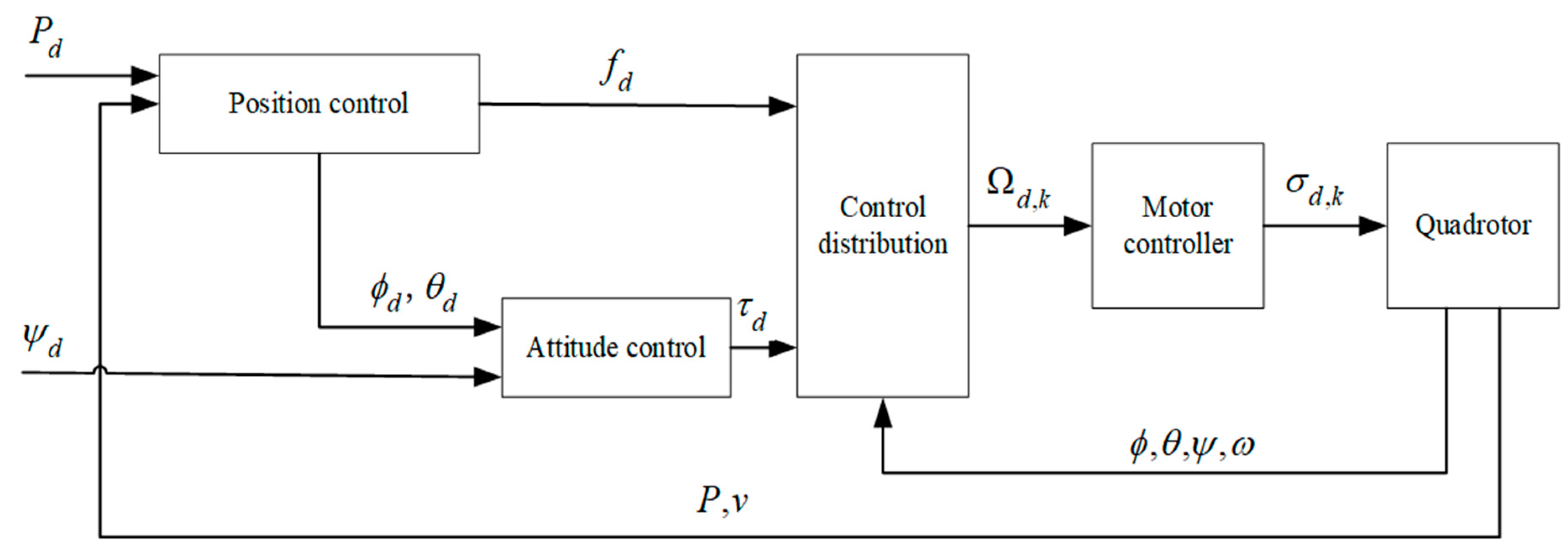
The PID control system of the quadrotor is based on a hierarchical control of inner and outer loops [49,50] and it can be further subdivided into four levels including position control, attitude control, control distribution and power distribution as shown in Figure 4.
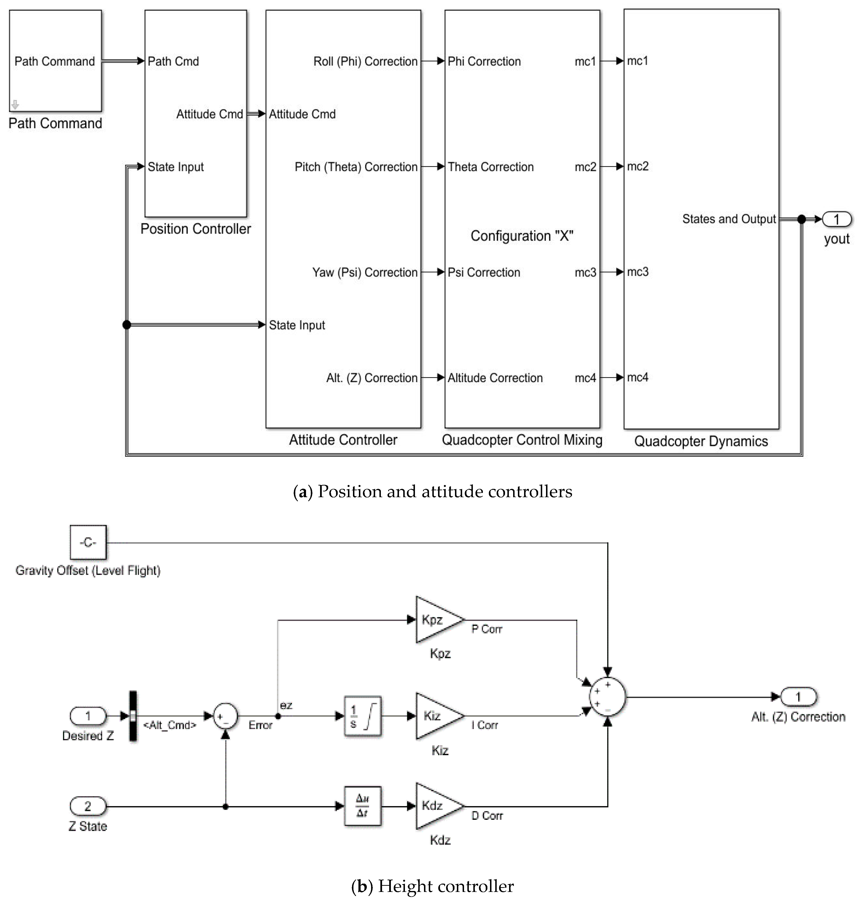
As the height control of the quadrotor has nothing to do with the attitude of the body, there is an independent feedback input z in the height control system and the height correction is output after the height PID controller. Due to the balance between gravity and lift when the quadrotor is hovering, it is necessary to add gravity compensation to the height controller. When there is no error in the height, the controller can still output a stable value to control the motor rotation to maintain the hovering state. The simulation structure of the height controller is shown in Figure 5.

3.3. Height and Vertical Velocity Based on a Cascade PID Controller

The cascade control system is one of the effective methods to improve the control quality and it has been widely used in process controls. The cascade PID controller is composed of a single loop PID regulator (as the main regulator) and an external set regulator (as a secondary regulator) connected in series to form a dual loop regulation system. The control output of the main regulator is used as the external set regulator and the control output of the external set regulator is sent to the control regulation structure.
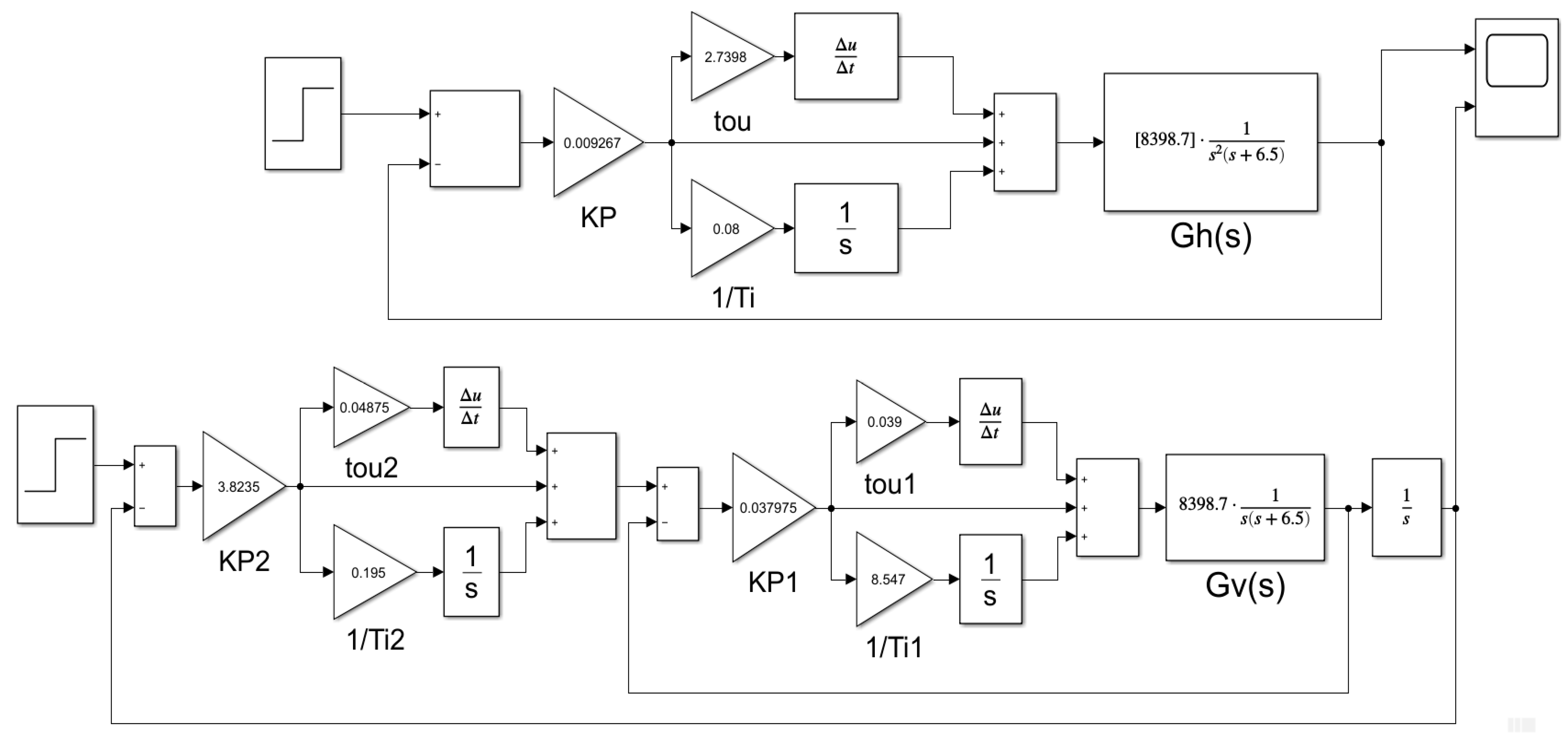
In order to improve the quality of height control effectively, a cascade PID based height controller system is designed as follows. The error between the expected height and the height measured by the range-finder is set as the outer loop feedback of the cascade PID controller, the expected vertical speed is obtained after the outer loop PID controller and then the difference between the expected vertical velocity and the actual vertical speed is set as the inner loop feedback input to accomplish the adjustment of the vertical speed, which finally realizes the dual loop control of the height and vertical speed. The control structure and Simulink are shown in Figure 6 and Figure 7.

4. Simulation and Experiment Evaluations

4.1. Simulink Parameter Tuning by Attenuation Curve

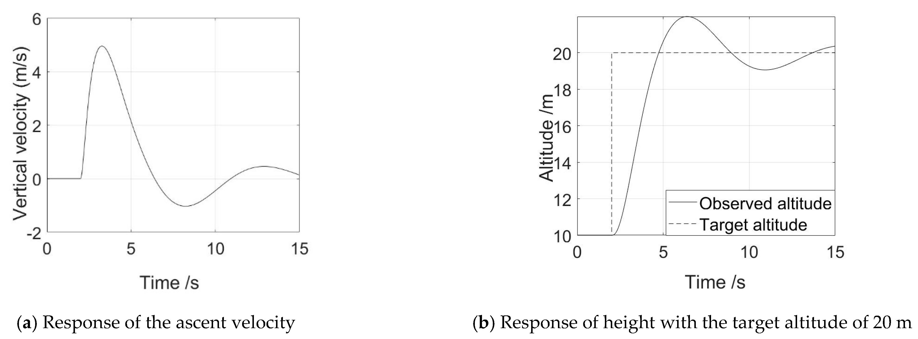
In order to obtain the optimal control effect, the parameters of the PID regulator need to be tuned. There are three common methods for PID parameter tuning in engineering: the Ziegler–Nichols tuning method, the critical proportionality method and the attenuation curve method. These three methods have their own characteristics: the Ziegler–Nichols tuning method is suitable for systems with a delay link in their open loop transfer function while the critical proportionality method requires the order of the system to be third-order or above and the attenuation curve method adjusts controller parameters by attenuation frequency characteristics [28]. If we suppose that the initial state of the quadrotor is x = [ 0 0 0 0 0 0 0 0 0 0 0 1 0 ] T and Ω i = [ 4100 4100 4100 4100 ] T , this means that the drone hovers at a height of 10 m and the simulation duration is set to 15 s. After 2 s, a position control command is given to make the aircraft rise to a height of 20 m and remain hovering. The simulation results are shown in Figure 8.
The rising speed shown in the left picture (a) first increases and then decreases after 2 s and then oscillates and stabilizes at about 0 m/s. The right picture shows that the height overshoots after reaching 20 m and finally stabilizes at 20 m.
According to the previously derived open loop transfer function Equation (31) of the height control system, the attenuation curve method is selected to tune the PID controller parameters and build the single-stage/cascade PID controller simulation block in Figure 8.
After setting up the control system structure in Simulink, first set the regulator parameters in the control system to a pure proportional action (Ti = , τ = 0) put the system into operation and then gradually adjust the proportionality δ from large to small until the ratio of the amplitude of the two adjacent periodic curves is 4:1 attenuation.
At this time, the ratio is 4:1, the attenuation ratio is δs, the rise time is tr and the time interval between two adjacent peaks is Ts. According to δs, tr or Ts, use the empirical formula in Table 2 to calculate each parameter value of the regulator [28].
The sequence of the PID controller parameter tuning is a proportional link first, then an integral link and then a derivative link. The parameters after tuning are:
K p = 0.009267 , T i = 12.5 , τ = 2.7398 .
In addition to the former requirements, the cascade PID controller must follow the inner first and then the outer setting rule. The parameters after tuning are:
Inner loop:
K p 1 = 0.037975 , T i 1 = 0.117 , τ 1 = 0.039 .
Outer loop:
K p 2 = 3.8235 , T i 2 = 5.1282 , τ 2 = 0.04875 .
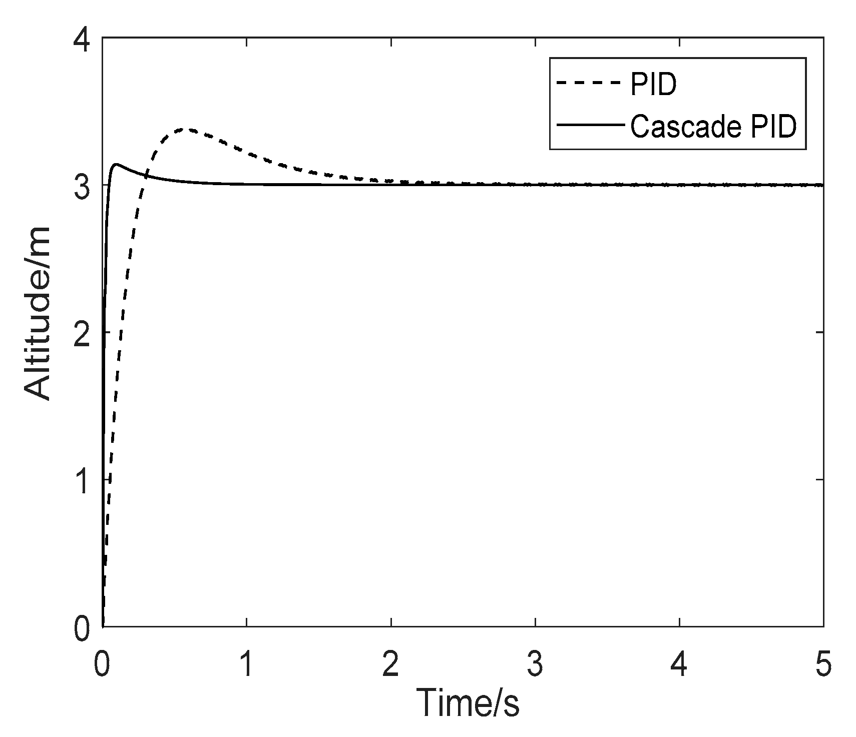
Set the expected value of the height to 3 m and then input the tuned parameters into the simulation system. After the system has run, the response curves of the single-stage PID controller and the cascade PID controller are shown in Figure 9.
It can be analyzed from Figure 9 that after the parameters are set by the attenuation curve method, the time it takes for the cascade PID controller to reach the expected height is reduced by 70% compared with the PID controller. The comparison of specific indicators is shown in Table 3 below.

4.2. Carton Box Avoidance Experiment

To simulate the drastic changes of relative height to the ground, we carried out a carton box avoidance experiment to validate the proposed control algorithm. The assembled quadrotor as the experimental platform used a core controller stm32f427 cortex M4 and output inertial data with an mpu9250 nine axis IMU. Lidar-lite V3, a high-precision laser-range-finder, was used in the ranging sensor. Its data update frequency can reach 400 Hz, which can meet the requirements of high dynamic ranging. The cascade PID control algorithm was transplanted to flight control. The laser-range-finder height was taken as the output of the outer loop and the change rate of the measured altitude with time was taken as the input of the inner loop. The control performance test was carried out in an open outdoor field in Southeast University, China. The wheelbase of our quadrotor was 400 mm and the parameters of its brushless motor are shown in Table 4.
In order to simulate the height mutation of ground obstacles, a 0.48 m high carton was placed on flat ground as shown in Figure 10. Considering the great influence of high winds before take-off, the expected height of the UAV was set as 1.9 m, the horizontal flight speed was set as 0.5 m/s and the UAV was manipulated to fly over the carton repeatedly for 10 times. The controlled variables and experimental scenarios in the experiment are shown in Table 5 and Figure 10, respectively. When the quadrotor was holding its altitude, the proposed controller should have detected the edge of the box and manipulated it to fly over the box.
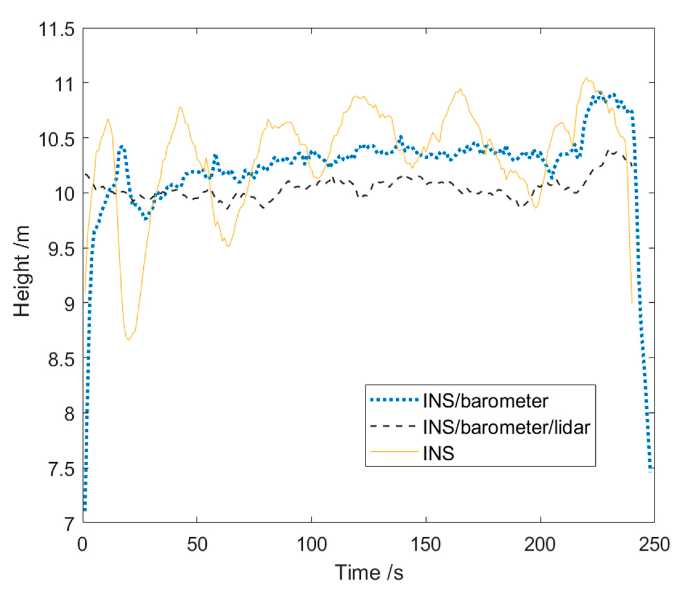
The resulting height data of the multi-sensor based controller can be seen in Figure 11 with the target height of 10 m above flat terrain. The difference in the performance of the height control clearly illustrates a better stability and sensitivity of the multi-sensor control. Therefore, the multi-sensor based control can react quickly especially with a reliable position and the velocity control in the z-axis.
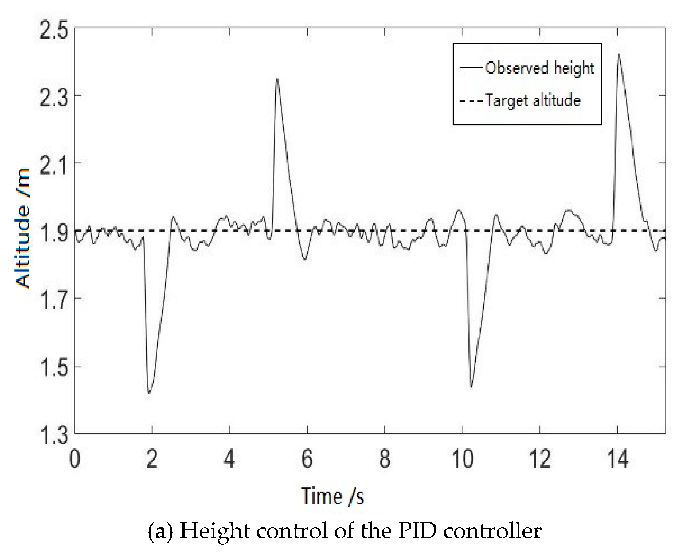
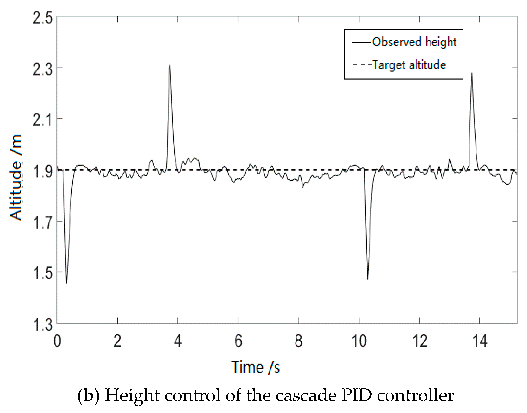
For the height control of the quadrotor, we implemented with a PID and a cascade PID controller, respectively. The laser-range-finder measurements for the two controllers and the target height (1.9 m) are shown in Figure 12.
From the comparison of the fixed height flight results in Figure 12a,b, it can be seen that the adjustment time of the cascade PID controller was much less than that of the PID controller in the case of sudden changes of the ground altitude. In addition, the stability of the cascade PID control was better than that of the PID. After considering the statistics of all of the height measurement data, the shortest time from detecting a height change to reaching the desired height was 1.13 s and the longest time was 1.66 s when using the PID controller; when using the cascade PID controller, the shortest time was 0.43 s and the longest time was 0.75 s. The adjustment time of the cascade PID controller improved over 50% than that of the PID controller.

5. Conclusions

This study investigated the position, attitude, velocity and height estimators based on GPS, accelerometers, gyroscopes and Lidar-lite onboard sensors, which were operated on a quadrotor of the Pixhawk open-source autopilot. For the terrain-following of the quadrotor, we have presented real-time height control, navigation and obstacle avoidance above outdoor undulant ground. In our system, GNSS and INS information were used to verify the position, velocity and attitude estimates with a constant height control for autonomous flights. The navigation and estimations depended on an available multi-sensor fusion. Apart from the absolute altitude estimation, the terrain-following required relative distance measurements from the Lidar-lite sensor. The proposed control algorithm was tested extensively in MATLAB Simulink simulations and then implemented on the real-world quadrotor vehicle. The results confirmed that the proposed combination of the multi-sensor fusion and cascade PID controller could ensure autonomous navigation, obstacle avoidance and height control, achieving better accuracy, response time and sensitivity. Future developments will fuse trajectory and velocity smoothing that enable the balance between control efficiency and terrain-following criteria.

Author Contributions

Conceptualization, Y.Y. and X.L.; Data curation, Y.H.; Formal analysis, Y.Y.; Funding acquisition, H.Y.; Methodology, Y.Y.; Resources, H.Y., Z.W. and X.L.; Software, T.Z.; Supervision, H.Y. and T.Z.; Validation, Y.H.; Visualization, T.Z. and Z.W.; Writing—original draft, Y.Y., Y.H. and T.Z.; Writing—review and editing, X.L. All authors have read and agreed to the published version of the manuscript.

Funding

This work was funded by the projects of the National Natural Science Foundation of China (Grant Number: 51979041, 61973079 and 61802428) and Zhishan Youth Scholar Program of Southeast University 2242020R40136.

Institutional Review Board Statement

Not applicable.

Informed Consent Statement

Informed consent was obtained from all subjects involved in the study.

Data Availability Statement

The following are available online at https://github.com/yangyuancsi/Altitude-control: PID: code for the PID controllers, Altitude estimation: code for the Kalman filter, Video: video for carton box avoidance experiment. The data used to support the findings of this study are available from the corresponding author upon request.

Conflicts of Interest

The authors declare no conflict of interest.

References

  1. Herisse, B.; Oustrieres, S.; Hamel, T.; Mahony, R.; Russotto, F. A general optical flow based terrain-following strategy for a VTOL UAV using multiple views. In Proceedings of the 2010 IEEE International Conference on Robotics and Automation, Anchorage, AK, USA, 3–7 May 2010; pp. 3341–3348. [Google Scholar]
  2. Armendariz, S.; Becerra, V.; Bausch, N. Bio-inspired Autonomous Visual Vertical and Horizontal Control of a Quadrotor Unmanned Aerial Vehicle. Electronics 2019, 8, 184. [Google Scholar] [CrossRef] [Green Version]
  3. Chang, G.; Xu, T.; Wang, Q.; Li, S.; Deng, K. GNSS attitude determination method through vectorization approach. IET Radar Sonar Navig. 2017, 11, 1477–1482. [Google Scholar] [CrossRef]
  4. Ponte, S.; Ariante, G.; Papa, U.; Del Core, G. An embedded platform for positioning and obstacle detection for small unmanned aerial vehicles. Electronics 2020, 9, 1175. [Google Scholar] [CrossRef]
  5. Kyriakis, P.; Moustris, G.P. Terrain Following for Fixed-Wing Unmanned Aerial Vehicles Using Feedback Equivalence. IEEE Control Syst. Lett. 2018, 3, 150–155. [Google Scholar] [CrossRef]
  6. Campos, I.; Nascimento, E.R.; Freitas, G.M.; Chaimowicz, L. A Height Estimation Approach for Terrain Following Flights from Monocular Vision. Sensors 2016, 16, 2071. [Google Scholar] [CrossRef] [Green Version]
  7. Hu, G.; Gao, S.; Zhong, Y.; Gao, B.; Subic, A. Matrix weighted multi-sensor data fusion for INS/GNSS/CNS integration. Proc. Inst. Mech. Eng. Part G J. Aerosp. Eng. 2016, 230, 1011–1026. [Google Scholar] [CrossRef]
  8. Qin, F.; Chang, L.; Jiang, S.; Zha, F. A Sequential Multiplicative Extended Kalman Filter for Attitude Estimation Using Vector Observations. Sensors 2018, 18, 1414. [Google Scholar] [CrossRef] [Green Version]
  9. Chang, L.; Hu, B. Robust Initial Attitude Alignment for SINS/DVL. IEEE/ASME Trans. Mechatron. 2018, 23, 2016–2021. [Google Scholar] [CrossRef]
  10. Batistoti, J.; Junior, J.M.; Ítavo, L.C.V.; Matsubara, E.; Gomes, E.; Oliveira, B.; De Souza, M.; Siqueira, H.; Filho, G.S.; Akiyama, T.; et al. Estimating Pasture Biomass and Canopy Height in Brazilian Savanna Using UAV Photogrammetry. Remote Sens. 2019, 11, 2447. [Google Scholar] [CrossRef] [Green Version]
  11. Micheletto, M.; Zubiaga, L.; Santos, R.; Galantini, J.; Cantamutto, M.; Orozco, J. Development and Validation of a LiDAR Scanner for 3D Evaluation of Soil Vegetal Coverage. Electronics 2020, 9, 109. [Google Scholar] [CrossRef] [Green Version]
  12. Li, H.; He, B.; Yin, Q.; Mu, X.; Zhang, J.; Wan, J.; Wang, D.; Shen, Y. Fuzzy Optimized MFAC Based on ADRC in AUV Heading Control. Electronics 2019, 8, 608. [Google Scholar] [CrossRef] [Green Version]
  13. Kyristsis, S.; Antonopoulos, A.; Chanialakis, T.; Stefanakis, E.; Linardos, C.; Tripolitsiotis, A.; Partsinevelos, P. Towards Autonomous Modular UAV Missions: The Detection, Geo-Location and Landing Paradigm. Sensors 2016, 16, 1844. [Google Scholar] [CrossRef] [PubMed] [Green Version]
  14. Xu, G.; Meng, T.; Zhang, H. Height Estimation of Ultrasonic Array Based on Integrated Navigation for UAVs. In Proceedings of the 2019 Chinese Control and Decision Conference (CCDC), Nanchang, China, 3–5 June 2019; pp. 287–292. [Google Scholar]
  15. Rothe, J.; Zevering, J.; Strohmeier, M.; Montenegro, S. A Modified Model Reference Adaptive Controller (M-MRAC) Using an Updated MIT-Rule for the Altitude of a UAV. Electronics 2020, 9, 1104. [Google Scholar] [CrossRef]
  16. Iqbal, J.; Xu, R.; Halloran, H.; Li, C. Development of a Multi-Purpose Autonomous Differential Drive Mobile Robot for Plant Phenotyping and Soil Sensing. Electronics 2020, 9, 1550. [Google Scholar] [CrossRef]
  17. Tang, W.; Wang, L.; Gu, J.; Gu, Y. Single Neural Adaptive PID Control for Small UAV Micro-Turbojet Engine. Sensors 2020, 20, 345. [Google Scholar] [CrossRef] [Green Version]
  18. Sieberling, S.; Chu, Q.; Mulder, J.A. Robust Flight Control Using Incremental Nonlinear Dynamic Inversion and Angular Acceleration Prediction. J. Guid. Control Dyn. 2010, 33, 1732–1742. [Google Scholar] [CrossRef]
  19. Kiji, S. PID vs LQR controller for tilt rotor airplane. Int. J. Electr. Comput. Eng. 2020, 10, 6309–6318. [Google Scholar]
  20. Huang, S.N.; Tan, K.K.; Lee, T.H. Further results on adaptive control for a class of nonlinear systems using neural networks. IEEE Trans. Neural Netw. 2003, 14, 719–722. [Google Scholar] [CrossRef]
  21. Han, G.; Fu, W.; Wang, W.; Wu, Z. The Lateral Tracking Control for the Intelligent Vehicle Based on Adaptive PID Neural Network. Sensors 2017, 17, 1244. [Google Scholar] [CrossRef] [Green Version]
  22. Munguía, R.; Urzua, S.; Grau, A. EKF-Based Parameter Identification of Multi-Rotor Unmanned Aerial VehiclesModels. Sensors 2019, 19, 4174. [Google Scholar] [CrossRef] [Green Version]
  23. Ma, X.; Tao, G. Adaptive Actuator Compensation Control with Feedback Linearization. IEEE Trans. Autom. Control 2000, 1, 1705–1710. [Google Scholar] [CrossRef]
  24. Doman, D.B.; Ngo, A.D. Dynamic Inversion-Based Adaptive/Reconfigurable Control of the X-33 on Ascent. J. Guid. Control Dyn. 2002, 25, 275–284. [Google Scholar] [CrossRef] [Green Version]
  25. Park, S.; Deyst, J.; How, J. A New Nonlinear Guidance Logic for Trajectory Tracking. In Proceedings of the AIAA Guidance, Navigation, and Control Conference and Exhibit, Providence, RI, USA, 16–19 August 2004; pp. 941–956. [Google Scholar] [CrossRef] [Green Version]
  26. Mahony, R.; Hamel, T.; Pflimlin, J.-M. Nonlinear Complementary Filters on the Special Orthogonal Group. IEEE Trans. Autom. Control 2008, 53, 1203–1218. [Google Scholar] [CrossRef] [Green Version]
  27. Feng, Y.; Chen, W.; Yang, L.; Wei, D. An Optimal Terrain Following Trajectory Online Regeneration Method. In Proceedings of the 2019 IEEE Conference on Control Technology and Applications (CCTA), Hong Kong, China, 19–21 August 2019; pp. 1074–1080. [Google Scholar]
  28. Idres, M.; Mustapha, O.; Okasha, M. Quadrotor trajectory tracking using PID cascade control. IOP Conf. Ser. Mater. Sci. Eng. 2017, 270, 12010. [Google Scholar] [CrossRef]
  29. Ren, J.; Liu, D.-X.; Li, K.; Liu, J.; Feng, Y.; Lin, X. Cascade PID controller for quadrotor. In Proceedings of the 2016 IEEE International Conference on Information and Automation (ICIA), Ningbo, China, 1–3 August 2016; pp. 120–124. [Google Scholar] [CrossRef]
  30. Kumar, Y.P.; Rajesh, A.; Yugandhar, S.; Srikanth, V. Cascaded PID Controller Design for Heating Furnace Temperature Control. IOSR J. Electron. Commun. Eng. 2013, 5, 76–83. [Google Scholar] [CrossRef]
  31. Saini, P.; Kumar, R.; Rajput, N. Cascade—PID control of a nonlinear chemical process. Nonlinear Stud. 2016, 23, 563–570. [Google Scholar]
  32. Simalatsar, A.; Guidi, M.; Buclin, T. Cascaded PID controller for anaesthesia delivery. In Proceedings of the 38th Annual International Conference of the IEEE Engineering in Medicine and Biology Society (EMBC), Orlando, FL, USA, 16–20 August 2016; pp. 533–536. [Google Scholar] [CrossRef] [Green Version]
  33. Wu, H.; Su, W.; Liu, Z. PID controllers: Design and tuning methods. In Proceedings of the 9th IEEE Conference on Industrial Electronics and Applications, Hangzhou, China, 9–11 June 2014; pp. 808–813. [Google Scholar]
  34. Shi, X.; Wang, Q.; Wu, Y. Research on Parameters Tuning of PID Controller Based on Critical Proportioning Method. In Proceedings of the 2016 International Conference on Electrical, Mechanical and Industrial Engineering; Atlantis Press: Amsterdam, The Netherlands, 2016; pp. 169–172. [Google Scholar]
  35. Zhu, Q.; Qiu, B. Research on Trajectory Tracking Control of Aircraft in Carrier Landing. In Proceedings of the Third International Conference on Instrumentation, Measurement, Computer, Communication and Control, Shenyang, China, 21–23 September 2013; pp. 1452–1455. [Google Scholar] [CrossRef]
  36. Henrique, A.; Fayad, K. Quadrotor Control using Optical-Flow Navigation. Master’s Thesis, Instituto Superior Técnico, Lisbon, Portugal, October 2014. [Google Scholar]
  37. Sokolovic, V.; Dikic, G. Stancic, R. Integration of INS, GPS, magnetometer and barometer for improving accuracy navigation of the vehicle. Def. Sci. J. 2013, 63, 451–455. [Google Scholar] [CrossRef] [Green Version]
  38. Tong, J.; Xu, X.; Zhang, T.; Zhang, L.; Li, Y. Study on Installation Error Analysis and Calibration of Acoustic Transceiver Array Based on SINS/USBL Integrated System. IEEE Access 2018, 6, 66923–66939. [Google Scholar] [CrossRef]
  39. Livshitz, A.; Idan, M. Adaptive Laser-Range-Finder Terrain-Following Approach. In Proceedings of the 27th Mediterranean Conference on Control and Automation (MED), Akko, Israel, 1–4 July 2019; pp. 612–617. [Google Scholar]
  40. Dill, E.T.; Young, S.D.; De Haag, M.U. GPS/Optical/Inertial Integration for 3D Navigation Using Multi-Copter Platforms. In Proceedings of the ION 2017 Pacific PNT Meeting, Honolulu, HI, USA, 1–4 May 2017; pp. 1093–1103. [Google Scholar] [CrossRef] [Green Version]
  41. Efe, M. Önder Sliding Mode Control for Unmanned Aerial Vehicles Research. Recent Dev. Ind. Control Syst. Resil. 2015, 22, 239–255. [Google Scholar] [CrossRef]
  42. Sabatino, F. Quadrotor Control: Modeling, Nonlinear Control Design and Simulation. Master’s Thesis, KTH, School of Electrical Engineering (EES), Stockholm, Sweden, 2015. [Google Scholar]
  43. Ahmed, A.H.; Ouda, A.N.; Kamel, A.M.; Elhalwagy, Y.Z. Attitude stabilization and altitude control of quadrotor. In Proceedings of the 12th International Computer Engineering Conference (ICENCO), Cairo, Egypt, 28–29 December 2016; pp. 123–130. [Google Scholar]
  44. Hetényi, D.; Gótzy, M.; Blázovics, L. Sensor fusion with enhanced Kalman Filter for altitude control of quadrotors. In Proceedings of the IEEE 11th International Symposium on Applied Computational Intelligence and Informatics (SACI), Timisoara, Romania, 12–14 May 2016; pp. 413–418. [Google Scholar] [CrossRef]
  45. Emran, B.J.; Al-Omari, M.; Abdel-Hafez, M.F.; Jaradat, M.A. A Cascaded Approach for Quadrotor’s Attitude Estimation. Procedia Technol. 2014, 15, 268–277. [Google Scholar] [CrossRef] [Green Version]
  46. Zhou, P.; Huang, G.; Zhang, L.; Tsang, K.F. Wireless sensor network based monitoring system for a large-scale indoor space: Data process and supply air allocation optimization. Energy Build. 2015, 103, 365–374. [Google Scholar] [CrossRef]
  47. Paing, H.S.; Schagin, A.V.; Win, K.S.; Linn, Y.H. New Designing Approaches for Quadcopter Using 2D Model Modelling a Cascaded PID Controller. In Proceedings of the IEEE Conference of Russian Young Researchers in Electrical and Electronic Engineering (EIConRus), St. Petersburg, Russia; Moscow, Russia, 27–30 January 2020; pp. 2370–2373. [Google Scholar]
  48. Zhang, X. Improved Kalman Algorithm for Vertical Height and Velocity Information Fusion of Multi-rotor Unmanned Aerial Vehicle. In Proceedings of the 39th Chinese Control Conference (CCC), Shenyang, China, 27–29 July 2020; pp. 3056–3059. [Google Scholar] [CrossRef]
  49. Hu, G.; Wang, W.; Zhong, Y.; Gao, B.; Gu, C. A new direct filtering approach to INS/GNSS integration. Aerosp. Sci. Technol. 2018, 77, 755–764. [Google Scholar] [CrossRef]
  50. Chang, G.; Xu, T.; Wang, H. M-estimator based robust unscented Kalman filter through statistical linearization. Trans. Inst. Meas. Control 2018, 41, 2016–2025. [Google Scholar] [CrossRef]
Figure 1. Multi-sensor based position, attitude and height control loops for terrain-following of the autonomous quadrotor.
Applsci 11 01065 g001
Figure 2. An airframe coordinate system and a geographic coordinate system.
Applsci 11 01065 g002
Figure 3. State function of the discretized fusion of the vertical velocity measurements.
Applsci 11 01065 g003
Figure 4. Closed loop block diagram of the autonomous control of the quadrotor.
Applsci 11 01065 g004
Figure 5. Simulink structures of the integrated control of the autonomous quadrotor.
Applsci 11 01065 g005
Figure 6. Structure of the cascade PID for the height and velocity control.
Applsci 11 01065 g006
Figure 7. Simulink structure of the cascade PID for the height and velocity control.
Applsci 11 01065 g007
Figure 8. Response curve of ascent velocity and height control.
Applsci 11 01065 g008
Figure 9. Dynamic response curve of the single-stage/cascade PID controller.
Applsci 11 01065 g009
Figure 10. Terrain-following experiment of the quadrotor above the ground with the cardboard box as the obstacle or the ground undulation.
Applsci 11 01065 g010
Figure 11. Comparison of the multi-sensor height control of the quadrotor above flat terrain.
Applsci 11 01065 g011
Figure 12. Comparison of the cascade PID height controllers for the quadrotor above a cardboard box on the ground.
Applsci 11 01065 g012aApplsci 11 01065 g012b
Table 1. Parameter list of the quadrotor.
ParameterUnitMeasurements
gm/s29.81
mkg1.12
lm0.225
cTN s2/rad21.394 × 10−7
cMN m s2/rad22.857 × 10−9
Ixxkg m20.0093
Iyykg m20.0088
Izzkg m20.0189
Table 2. PID regulator parameter tuning based on the attenuation curve method.
ControllerProportional Band
δ
Integration Time
T i
Derivative Time
τ
P δ s 0
PI1.2 δ s 2 t r / 0.5 T s 0
PID0.8 δ s 1.2 t r / 0.3 T s 0.4 t r / 0.1 T s
Table 3. Dynamic performance indicators of single-stage/cascade PID.
Dynamic Performance IndexPIDCascade PID
Overshoot M p 12.6%4.6%
Settling time t s ( s ) 4.4271.352
Rise time t r ( s ) 0.8070.540
Peak time t p ( s ) 1.3380.190
Table 4. Parameters of the brushless motor.
ParameterValue
m / kg 1.2
K 1542
T m 0.153
Table 5. Variable setting of the experiment.
VariablesValues/m
Height of the obstacle (the box)0.48
Width of the obstacle (the box)1.2
Travel speed of the quadrotor (m/s)0.5
Publisher’s Note: MDPI stays neutral with regard to jurisdictional claims in published maps and institutional affiliations.