Abstract
Augmented reality (AR)-based surgical navigation may offer new possibilities for safe and accurate surgical execution of complex osteotomies. In this study we investigated the feasibility of navigating the periacetabular osteotomy of Ganz (PAO), known as one of the most complex orthopedic interventions, on two cadaveric pelves under realistic operating room conditions. Preoperative planning was conducted on computed tomography (CT)-reconstructed 3D models using an in-house developed software, which allowed creating cutting plane objects for planning of the osteotomies and reorientation of the acetabular fragment. An AR application was developed comprising point-based registration, motion compensation and guidance for osteotomies as well as fragment reorientation. Navigation accuracy was evaluated on CT-reconstructed 3D models, resulting in an error of 10.8 mm for osteotomy starting points and 5.4° for osteotomy directions. The reorientation errors were 6.7°, 7.0° and 0.9° for the x-, y- and z-axis, respectively. Average postoperative error of LCE angle was 4.5°. Our study demonstrated that the AR-based execution of complex osteotomies is feasible. Fragment realignment navigation needs further improvement, although it is more accurate than the state of the art in PAO surgery.
1. Introduction
The main surgical objective of the periacetabular osteotomy of Ganz (PAO) is the restoration of the hip joint anatomy [1]. PAO is typically performed in young adults who suffer from residual hip dysplasia (RHD). RHD is a condition characterized by insufficient acetabular coverage of the femoral head and is a long-known cause for hip pain and development of osteoarthritis (OA), which continuously progresses to a point of severity where it can only be treated by total hip arthroplasty (THA) [2,3,4,5,6]. The surgical execution of a PAO is very demanding and hence associated with a high complication rate between 6% to 37% [7]. Since the incision area does not allow for direct sight on all of the anatomy involved, the osteotomies and reorientation are mainly guided by intraoperative fluoroscopy and anatomical landmarks [8]. Known complications even in experienced surgeons include intra-articular extensions of the osteotomies, discontinuity of the pelvic ring, injury to the sciatic nerve, incorrect reorientation, and heterotopic ossifications [3,9,10,11,12]. For the PAO procedure, originally described in Ganz et al. [1], the patient is positioned supine on the operating table. For exposure a modified anterior approach (Smith-Petersen) is used. The acetabular fragment (Figure 1, in green) is mobilized by four osteotomies namely the ischial, pubic, supra- and retroacetabular osteotomy (Figure 1, marked as 1, 2, 3 and 4, respectively). For the first osteotomy (ischial), an angled chisel is used (Figure 2, step 6). Immediately adjacent to the acetabulum, the second osteotomy (pubis) is performed with a chisel. The third osteotomy (supraacetabular) is performed with an oscillating saw and ends at the crossing point (Figure 2, step 7) with the fourth (retroacetabular) osteotomy. About 15 mm of the fourth osteotomy are performed from inside and outside at an angle of 120° using the chisel, whereas the remainder towards the ischial spine breaks through a controlled fracture (Figure 1, orange circle), thereby freeing the acetabulum from the pelvic bone. The mobile fragment is then reoriented to the planned target position, where it is fixed to the remaining pelvis with two cortical screws on the iliac crest (Figure 1, screws shown in gray, iliac crest area marked in blue) [1].
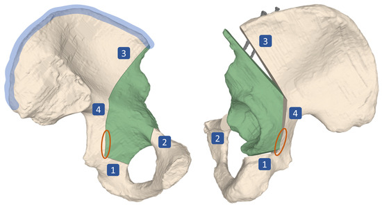
Figure 1.
Surgical technique of periacetabular osteotomy of Ganz (PAO). Four osteotomies, namely the ischial (1), pubic (2), supra- (3) and retroacetabular (4) are performed, followed by a controlled fracture (area marked in orange), which mobilizes the acetabular fragment (green). The fragment is then reoriented in space before it is fixed to the remaining pelvis by two screws (shown in gray) at its target position. The area marked in blue is called the iliac crest. Left: lateral view on the pelvis, preoperatively. Right: Medial view on the pelvis, postoperatively.
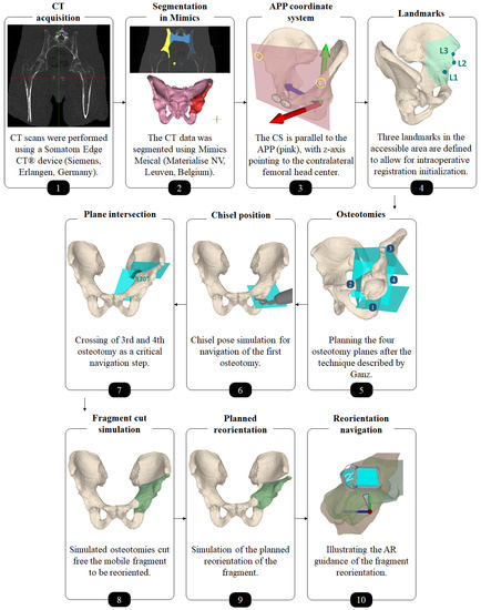
Figure 2.
Overview of the preoperative planning workflow.
For diagnosis and preoperative planning of RHD, conventional two-dimensional (2D) anterior-posterior (AP) radiographs are used to determine two parameters, the lateral center-edge (LCE) angle and the acetabular index (AI) (Figure 3) [13]. A hip is considered dysplastic, if the LCE angle is less than 23° with an AI of more than 14°, whereas an LCE angle exceeding 33° with an AI of less or equal than 2° is considered acetabular overcoverage [14,15]. Although the limitations of 2D measurements in assessing complex three-dimensional (3D) anatomies are well known, they still represent the gold standard in the preoperative planning of hip surgeries due to the lack of adequate 3D measurement methods. Studies have shown that 2D measurements are biased by the projection of the anatomy in the radiographs [16,17,18,19,20,21,22,23] and the intra- and inter-reader variability of the measurement methods [20,24,25,26]. This underlines the need for a more robust 3D preoperative planning method in order to accurately determine and implement the optimal correction. However, the existing clinically used preoperative 3D planning approaches [27,28,29,30,31] are still relying on the 2D parameters LCE and AI and are therefore not true 3D approaches.
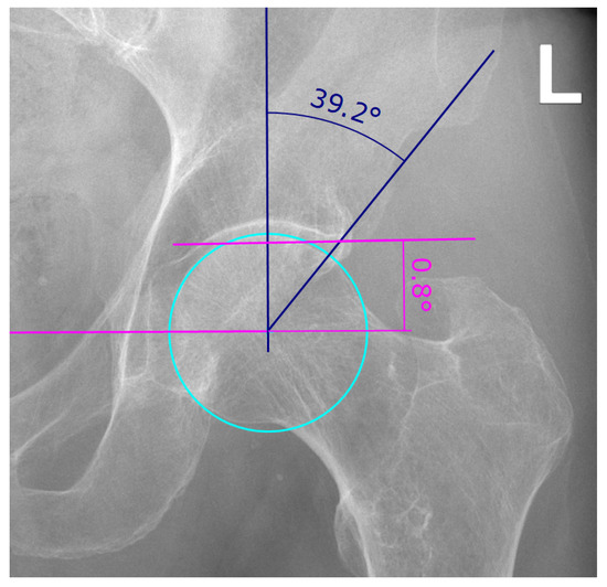
Figure 3.
Example of lateral center-edge angle (LCEA) and acetabular index (AI) measurement on an AP pelvic radiograph as described in [13]. The LCEA and AI are a measure for the extent of coverage of the femoral head by the pelvic part of the hip joint, the acetabulum. The LCEA is measured between two lines, both starting in the femoral head center, one vertical line and the line drawn between femoral head center and the most lateral point of the acetabular rim (angle in blue). To find the femoral head center, a circle is drawn (cyan). The vertical line of the LCEA is defined as being perpendicular to the line connecting both femoral head centers (pink). The AI is measured between said pink line connecting both femoral head centers and a line running through the medial edge of the sclerotic acetabular zone and through the lateral sourcil (angle in pink).
The limitations of the preoperative planning and the challenges of the surgical execution have motivated the development of computer-assisted navigation approaches for PAO. In 1997, Langlotz et al. [32] presented an approach enabling guided osteotomies through instruments that were tracked optically by an external system and visualized with respect to preoperative computed tomography (CT) data. Correspondence between intraoperative anatomy and the preoperative CT was found by either a landmark- or surface-based matching strategy. A reference marker compensated for anatomy motion. If the contralateral side was chosen for the reference marker, an additional incision became necessary. At a later stage of development, it was also possible to guide the reorientation of the acetabular fragment through a tracked handle. In total, 14 surgeries were conducted, yielding satisfactory results without complications [33,34]. The approach of Armand et al. [28] not only allowed for implementation of a 3D preoperative plan but included biomechanical considerations, namely the contact pressure distribution on the acetabular cartilage based on discrete element analysis, along with geometrical information. Motion compensation was only limited by using three screws that were digitized using a tracked pointer before starting the osteotomies. If tracking was lost due to motion of the hip anatomy, the surgeon had to re-digitize these screws to restore registration. Hsieh et al. [35] compared their computer-assisted approach to the conventional approach in a study with a two year follow-up. Intraoperative movement of the anatomy was tracked by a reference marker at the iliac crest (Figure 3, marked in blue) that required an additional incision. After the fragment was freed, it was not tracked anymore and therefore reorientation was not guided. Reduced radiation and operation time in the computer-assisted group were the main findings. No significant differences in operative blood loss, transfusion requirement, correction of deformity and functional improvement were found and there were no complications in both groups. The study of Abraham et al. [36] investigated computer-assisted PAO in terms of osteotomy and fragment reorientation accuracy in 3D on five cadaveric hips. Osteotomies were guided by a tracked drill bit guide. Fragment reorientation was achieved by matching landmarks at K-wire locations (for fixation) to the preoperative plan. Postoperative CT evaluation showed that preoperatively planned goals could be realized. The results of Liu et al. [27], who performed eight surgeries on four cadavers, suggest similar conclusions. However, the final alignment was not measured by postoperative CT, but intraoperatively. All of the aforementioned approaches employ external optical tracking systems, which come along with line-of-sight impediment and, consequently, with poor usability. Pflugi et al. [37] came up with an alternative idea, proposing the registration and tracking for fragment reorientation through inertial measurement units (IMU). One IMU was fixated on the pelvis, the other one on the fragment. A revised version [38] included a small camera in the pelvis IMU facing and tracking a marker attached to the fragment IMU. Sensor fusion combined the two estimates. Both systems were validated w.r.t. an external optical tracking system using bone models and cadavers. The authors could show similar accuracy and high correlations with the tracking system. Nevertheless, in all described approaches visual feedback was provided only through 2D monitors located in the periphery of the operating room (OR). This significantly complicates the process of aligning navigation information with the actual surgical site [39]. Generally, there is consensus that computer assistance is beneficial for PAO in different aspects, also supported by long-term studies involving a high number of patients [40]. However, we believe that usability must be further increased to achieve a broad clinical acceptance [41].
Augmented reality (AR) has opened up new possibilities in orthopedic surgery [42] as described in a recent review paper [43]. In situ visualizations can provide surgeons with an intuitive understanding of the underlying 3D anatomy, resolve the cognitive load of aligning the working space with the one of preoperative data and facilitate surgical guidance. Instruments can be displayed at their target position. Particularly interesting are recently developed off-the shelf optical see-through head-mounted displays (OST-HMD). Their feasibility as a surgical navigation device has not been fully explored yet and is still under discussion [44,45]. Although preliminary studies showed promising results in various orthopedic interventions, for example, pedicle screw placement [46,47], percutaneous procedures [48,49,50] and hip resurfacing [51], OST-HMD may still suffer from a poor navigation accuracy dependent on the approach taken [44]. In order to render AR content correctly in space, OST-HMD need to know their pose w.r.t. the target object(s). One approach is to employ an external device/camera and estimate the relevant poses from an outside viewpoint (outside-in tracking) using the OST-HMD only as a video see-through device, such as in [50,52]. The second solution is referred to as inside-out tracking in which the OST-HMD uses its sensors to localize itself either relative to markers (marker-based) or by simultaneous localization and mapping (SLAM) [53] its surrounding (marker-less). In light of the previously mentioned line-of-sight problem, inside-out tracking may be arguably favorable. Marker-based inside-out tracking, as employed in [54,55], stands out with its simplicity, as the OST-HMD only needs to perform common marker detection, whereas marker-less inside-out tracking often comprises multiple sensor and sophisticated sensor fusion algorithms. This way, however, it enables a world coordinate system where renderings and poses are maintained over time and independent of OST-HMD movements. Furthermore, the surgeon is not disturbed by markers attached to the anatomy.
In a proof-of-concept study on synthetic bone models, Kiarostami et al. [56] were the first describing a marker-less inside out approach for the AR-based surgical navigation of PAO osteotomies. AR guided osteotomies performed by novice surgeons were as accurate as when performed in a freehand fashion by an experienced PAO surgeon. However, their approach did not support surgical navigation of fragment reduction, which is an essential step of PAO intervention and thus motivation for our study. To this end, we extended the marker-less inside out approach to the navigation of the fragment reduction as described in our previous case study [57]. In this pilot experiment, a surgeon tested the approach for the first time on a single cadaver. The goal of our current study was now to present the complete pipeline for the AR-based navigation of PAO including 3D preoperative planning, surgical execution and postoperative accuracy evaluation and two evaluate its accuracy prospectively in ex-vivo experiments. We wanted to determine (a) whether it is feasible to execute a 3D preoperative plan of PAO on under AR-based surgical navigation with an OST-HMD (Microsoft HoloLens, Microsoft Corporation, Redmond, WA, USA), (b) how accurately the osteotomies can be executed using visual guidance, and (c) how accurately the acetabular fragment can be reoriented using visual and quantitative guidance. To this end, two surgeries on human cadavers were performed and evaluated on postoperative CT.
2. Materials and Methods
This study included two thawed fresh-frozen human cadaveric hips (one side each) without history of trauma, malformation, tumor or surgery. Preoperative planning and AR-based surgical navigation are described in the following subsections.
2.1. Preoperative Planning
Each cadaver was CT scanned using a Somatom Edge CT® device (Siemens, Erlangen, Germany). The slice thickness was 1.0 mm and the in-plane resolution (x-y) was 0.4 × 0.4 mm (Figure 2, step 1). 3D models of pelves and femora were extracted using the global thresholding and region growing functionalities of a commercial segmentation software (Mimics Medical, Materialise NV, Leuven, Belgium) [58,59,60] (Figure 2, step 2).
An experienced orthopedic surgeon conducted the 3D preoperative planning. An in-house developed software was used (CASPA, Balgrist University Hospital, Zurich, Switzerland). For navigation and outcome evaluation, we defined an anatomical coordinate system with its origin in the formal head center, where the y- and z-axes are parallel to the anterior pelvic plane (APP) and the z-axis pointing to the contralateral femoral head center (Figure 2, step 3). The APP is spanned by 4 landmarks: the right and left ASIS (yellow circles in Figure 2, step 3) as well as the right and left pubic tubercle (gray circles in Figure 2, step 3) [61]. The choice of this coordinate system is motivated by the conventional, X-ray based PAO planning, because the APP corresponds with the perspective of an anterior X-ray. In CASPA, three anatomical landmarks were defined at the iliopubic eminence (Figure 2, step 4: L1), the anterior inferior iliac spine (AIIS) (Figure 2, step 4: L2) and at the deepest point of convexity between anterior superior (ASIS) and inferior iliac spine (AIIS) (Figure 2, step 4: L3), required later for intraoperative registration initialisation of the preoperative plan to the patient anatomy. The software allows to define 3D osteotomy plane objects which can be translated and rotated freely in 3D space. For each of the four osteotomies, such a plane object was created and placed according to Ganz’ original description [1] (Figure 2, step 5). Thanks to the AR technology, all plane objects can be later in-situ visualized on the real anatomy to navigate the cuts. For the first osteotomy (ischial), we additionally planned the poses of the chisel such that the surgeon could align the physical instrument intraoperatively (Figure 2, step 6). The idea for guiding the direction of the supraacetabular osteotomy was to visualize a plane and a crossing point which marks the end point of the supraacetabular osteotomy and the beginning of the retroacetabular osteotomy. According to Ganz et al., said crossing point should be at an angle of 120° and was AR-displayed as a cross in addition to the planes (Figure 2, step 7). After the crossing point, only a small part of the retroacetabular cut can performed with the use of a chisel, while the remaining osteotomy has to be performed as a controlled fracture toward the ischial spine [1]. Therefore, adequate guidance of the retroacetabular osteotomy by visualizing the crossing point along with the osteotomy plane was crucial to prevent fracture of the posterior column, which is considered a severe surgical error [1].
Separating the acetabular fragment from the remaining pelvis was realized by Boolean operations [62] between the pelvic 3D model and the cutting plane objects (Figure 2, step 8). As both cadavers had a physiological hip anatomy, the acetabulum was planned to be rotated laterally and anteriorly in order to achieve a fragment transformation similar to the correction of developmental hip dysplasia through PAO. To this end, the surgeon manipulated the fragment in space via mouse interaction towards the desired target pose (Figure 2, step 9). Equal amount of correction was planned for both cadavers, whereas for cadaver 1 we planned the correction on the left hip joint and on cadaver 2, the right side underwent surgery.
2.2. AR-Based Surgical Navigation
Our navigation method should provide AR-based surgical navigation for performing osteotomy cuts and reorientation of the acetabular fragment according to the preoperative plan. The following major steps were required: registration initialization, fine registration, tracking of the pelvis, visualization of osteotomy planes/chisels and tracking of the fragment.
An orthopedic surgeon performed the procedure under realistic OR conditions using the Microsoft HoloLens (Microsoft Corporation, Redmond, WA, USA) as the OST-HMD. Throughout the intervention, the surgeon interacted with the OST-HMD via voice commands, to proceed to the next step of the navigation workflow as well as for displaying or hiding certain objects. Following the PAO description of Ganz [1], a modified Smith-Peterson approach was conducted to expose the pelvis bone. Next, two custom-made 3D printed mounts equipped with markers were attached to the pelvis and the assumed region of the fragment using small screws (Figure 4a). The markers enabled tracking of pelvis and the acetabular fragment during navigation. The mount was designed such that it did not interfere with the surgeon or the surgical instruments during the procedure and did not cause additional damage to the anatomy. The steps to be performed under AR-based surgical navigation can be subdivided into three parts: registration, osteotomy guidance and fragment reorientation guidance. An overview of the entire workflow can be found in Figure 5. In the following, a detailed description of our approach and all performed steps is given.
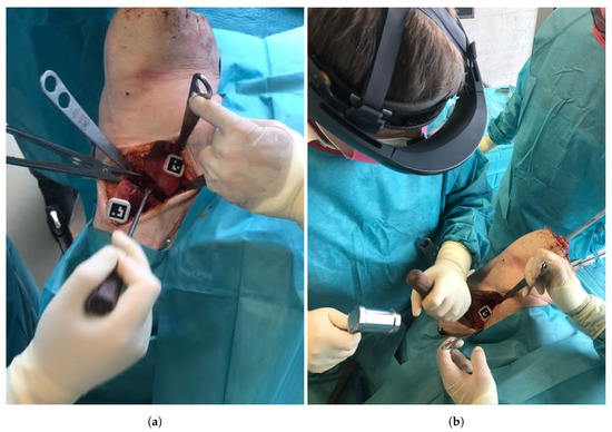
Figure 4.
(a) The pelvic and fragment mounts equipped with markers and fixated to the anatomy. (b) The surgeon during the procedure wearing the HoloLens.
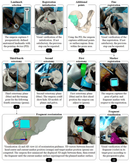
Figure 5.
Workflow of the augmented reality (AR)-based surgical navigation. Please note that the pelvic bone in this image is shown opaque, as different rendering options could be chosen by the surgeon. The impression of visual misalignment is caused by the stereo-rendering technique which generates two images optimized to the left and right eye of the user.
2.2.1. Registration
Our registration approach is based on our previous work on radiation-free surface digitization of the spinal anatomy [47] using a 3D printed pointing device (PD, Figure 5, step 1). The PD was designed such that a sterile marker (Clear Guide Medical, Baltimore, MD, USA) could be attached to it at a predefined position. The marker showed an AprilTag [52,63] pattern, which could be tracked by the two front-facing cameras of the HoloLens as described in the following. Please refer to Figure 6 for an overview of coordinate systems and transformations used in this subsection.
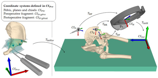
Figure 6.
Overview of coordinate systems and transformations. A transformation from coordinate system A to coordinate system B is denoted as . is the preoperative planning space defined by the computed tomography coordinate system and is the intraoperative space defined by the HoloLens on application startup. is the pose of the planning in . and are the pre- and planned postoperative fragment poses in . is the final registration. , and are the local coordinate systems of the pointing device, pelvic marker and fragment marker, respectively. is the local coordinate system of the HoloLens, defined by its built-in marker-less inside-out tracking [64].
Each camera detected the AprilTag using the detection functionality (pipeline of thresholding, contour filtering, bits extraction, marker identification and corner refinement) of the ArUco library [65,66], which yields four 2D corner coordinates in a sorted manner for each image (left and right). The corner coordinates are then mapped to the respective image planes. For each corresponding corner in the left and right image, a ray from the camera origin through the image plane is formed and the closest point between the two rays is found by triangulation. The result consists of four 3D point estimates, one for each corner. However, these point estimates usually do not form a perfect square and are not coplanar. To solve this problem, the known 3D ground truth shape of the marker is mapped to the point estimates by applying Horn’s absolute orientation method [67]. The found solution is then used as the 6DoF marker pose. Due to the known geometry of the PD, fabricated with a printing tolerance of 0.1 mm, its tip position in world space can be inferred without the need of manual calibration by (Figure 6).In the first part of the registration procedure - the initialization-the surgeon manually captured the three preoperatively defined landmarks (Figure 2, step 4) at the iliopubic eminence (Figure 2, step 4: L1), the anterior inferior iliac spine (AIIS) (Figure 2, step 4: L2) and at the deepest point of convexity between anterior superior (ASIS) and inferior iliac spine (AIIS) (Figure 2, step 4: L3) using the PD (Figure 5, step 1). Applying Horn’s absolute orientation method [67] to the intraoperatively captured landmarks and their preoperatively defined counterparts led to an initialization of (Figure 6) that was visually verified (Figure 5, step 2). If the result was not satisfactory, the initialization step could be repeated. Otherwise, the surgeon continued by sampling 10 to 15 additional points from accessible and well-suited areas on the pelvic bone, namely the area between superior and inferior iliac spine, the ala ossis ilii, the quadrilateral space or the pelvic brim (Figure 5, step 3, green area). Starting from the initialization, these points were then registered to the preoperative 3D model by repeating the two ICP [68] steps being (1) building pairs of nearest neighbors using the KD-tree implementation of ALGLIB (ALGLIB Project, Nizhny Novgorod, Russia) and (2) applying Horn’s absolute orientation method to those point pairs until the root-mean-square error between the point pairs was below a heuristically determined threshold of 0.001 mm, leading to the final registration (Figure 6).
Once the registration was verified (Figure 5, step 4), it was possible to express the preoperative planning including the pelvic bone () and the current and desired acetabular fragment positions ( and , respectively) in the intraoperative coordinate system (Figure 6). To formally describe the tracking of said anatomy, we introduce the following two definitions.
Definition 1.
Let and be the marker poses of in (Figure 6) at the time of registration and at the current time step, respectively.
Definition 2.
Let and be the marker poses of expressed relative to (Figure 6) at the time of registration and at the current time step, respectively.
The marker positions, which are obtained in real-time, were then used to update the positions of the models as follows:
The intervention requires to work with surgical tools such as chisels or surgical saws which induces motion of the anatomy. Therefore, it may happen that the overlay between preoperative plan and intraoperative anatomy is lost and a motion compensation strategy becomes necessary. Our approach implicitly allows motion compensation by querying the pelvis marker pose and updating Equations (1)–(3) when needed. For providing real-time feedback during fragment reorientation, the fragment pose defined in Equation (2) is updated in real-time with respect to the fragment marker.
2.2.2. AR-Based Navigation of the Osteotomies
In order to guide the osteotomies, planes for supra- and retroacetabular cuts and chisel poses for the ischial cut, respectively, were rendered in situ on the anatomy (Figure 5, steps 6–8). By rendering the pelvic bone in transparent with a black material, the intersections between virtual planes and real pelvic anatomy could be optimally perceived. The surgeon was able to switch between the options of rendering the bone in transparent black or opaque original color. The pubic osteotomy was performed freehand without AR-based navigation because it is a straight and simple cut that does not require accurate execution.
2.2.3. AR-Based Navigation of the Acetabular Fragment Reorientation
For the reorientation guidance (please refer to Figure 5, step 9), two 3D vectors were computed: one between femoral head center and current marker position (orange) and one between femoral head center and target marker position (green). Their deviation is displayed as a 3D angle on the current marker surface (cyan with number). The surgeon first tried to align these vectors and then rotated the fragment such that the current marker surface superimposed the planned marker surface (cyan without number). Visual verification of the reorientation in comparison to a rendering of the fragment at its planned pose was also possible (Figure 5, step 10). When the reorientation was considered satisfactory, the acetabular fragment was fixated to the pelvic bone with screws. Finally, the wound was closed layer by layer.
3. Results
A detailed description of our postoperative outcome measurement method as well as the evaluation of our results are reported in the following sections.
3.1. Outcome Measures
Both cadavers were CT scanned postoperatively and 3D models were extracted following the same workflow as described in Section 2.1. Pre- and postoperative models of the pelvic bone were registered using ICP [68,69] enabling the 3D comparison of the preoperative plan with the postoperative models in a common coordinate system. Please refer to Figure 7 for the following description of outcome measures [57].
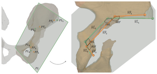
Figure 7.
Visualization of outcome measures. The left image shows 3D osteotomy starting points and the projection plane for 2D measurements, which are shown on the right: projected osteotomy starting points, their connecting vectors and the angles between supra- and retroacetabular osteotomy and between retroacetabular and ischial osteotomy, respectively.
One key measure of the outcome evaluation were the planned and performed osteotomy starting points and , respectively. They were defined as follows:
- : most lateral point on intersection between supraacetabular osteotomy plane and corresponding pelvic 3D model (pre- and postoperative, respectively)
- : most superior points on intersecting line between supraacetabular and retroacetabular osteotomy planes
- : most superior points on intersecting line between retroacetabular and ischial osteotomy planes
- : most inferior point on intersection between ischial osteotomy plane and corresponding pelvic 3D model (pre- and postoperative, respectively)
For 2D measurements, and were projected onto a plane defined as the best fit in a least-squares sense by (Figure 7). The projected points are denoted as and and the vectors connecting these points are:
The 2D angle between supra- and retroacetabular osteotomy is denoted as (planned) and (performed), and the one between retroacetabular and ischial osteotomy is denoted as (planned) and (performed). For both cadavers, the following outcome measures were calculated:
- The 3D point distance between each pair of starting points and
- The 2D angle between each pair of projected starting point connecting vectors and
- The absolute 2D angle deviation between and and the absoulte deviation between and .
- The 3D absolute rotational errors in Euler angles between planned and performed fragment reorientation w.r.t. our APP CS.
- The LCE angles (planned and performed), determined by the angle between the y-axis of our APP CS and the vector connecting the origin of the CS and the projection of the most lateral point of the acetabular rim onto the y-z-plane of the CS.
3.2. Outcome Evaluation
The mean 3D distances between starting points and was 14.9 mm, between and it was 10.8 mm, between and it was 8.7 mm and between and it was 8.9 mm. The 2D angles between each pair of projected starting point connecting vectors and averaged at 5.3°, the one between and at 1.0° and the one between and at 9.8°. The mean absolute 2D angle deviations between and and between and were 4.6° and 9.1°, respectively. For the fragment reorientation, the average absolute rotational errors in Euler angles were 6.7°, 7.0° and 0.9° for the x-, y- and z-axis. The mean absolute difference between planned and performed LCE angles was 4.5°.
Table 1 and Table 2 show the results of the AR guided osteotomies and the AR guided fragment reorientation, respectively. Furthermore, as given in Table 3, we evaluated the LCE angles of the planned and performed reorientation. For a visual evaluation of the results please refer to Figure 8.

Table 1.
Results of the AR guided osteotomies.
Table 2.
3D results of the AR guided fragment reorientation.
Table 3.
2D results of the AR guided fragment reorientation.
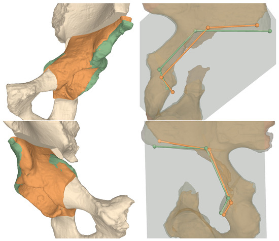
Figure 8.
3D comparisons between preoperative plans and postoperative models for Cadaver 1 (top row) and Cadaver 2 (bottom row). Left column shows the fragment orientations, right column the projected osteotomy starting points and their connecting vectors. Green: planned, orange: performed.
4. Discussion
Computer assistance for PAO has been studied for more than two decades with the first study being published in 1997 [32]. Although there is a strong consensus about the benefits in terms of accuracy and safety, computer-assisted surgical navigation of PAO could not be established successfully in clinical practice [70]. In our opinion the main reason is the lack of usability which makes existing approaches still complicated and cumbersome [41]. They depend on an external optical tracking system [26,28,32,33,34,35,36] suffering from line-of-sight issues and provide visualizations on an off-field workstation which complicates the surgeon’s task of interpreting and executing the 3D navigation cues correctly [39].
In this study, we proposed a radiation-free AR-based surgical navigation approach, running locally on an OST-HMD with no need for an external tracking system. Navigation cues are superimposed with the patient anatomy directly at the surgical site. AR provides information regarding perspective and interaction in a way that is easier and more natural to interpret for humans and thus enables intuitive surgical guidance and safe execution. Navigation is further simplified by allowing visualization of instruments at their preoperatively planned position (e.g., chisels), which eliminates the challenges associated with instrument tracking. When tracking is still required (e.g., for registration or fragment reorientation), it is realized using the front-facing built-in cameras of the OST-HMD without interfering with the surgeon’s natural hand-eye-coordination.
The accuracy of the surgical execution using our navigation approach was evaluated with respect to osteotomies and fragment reorientation by comparing pre- and postoperative CTs of the cadaver surgeries. To this end, a 3D model of the postoperative CT was reconstructed and registered to the preoperative plan using ICP [68,69]. The planned and performed osteotomy starting points were measured and the 3D distance between them was calculated. Kiarostami et al. [56] followed the same approach in their feasibility study for AR guided PAO osteotomies on synthetic bone models using a landmark-based registration. In their study, the experienced surgeon achieved an average accuracy of 2.4 mm as opposed to 10.8 mm in the herein presented study. Our starting point accuracy was also inferior to the cadaveric study reported by Abraham et al. [36]. Their study investigated the performance of computer-assisted PAO using a marker-based outside-in approach and a high-end tracking system. Regarding the osteotomies, only the iliac cut was evaluated yielding an average distance of 1.97 mm compared to 9.7 mm (overall mean) herein presented. However, it has to be taken into account that their cadavers were debrided from soft tissue and ligaments and that postoperative measurements were only performed on a single CT slice, which makes the measurements less sensitive. Nevertheless, the accuracies of navigating the four postoperative starting points with our approach are considered clinically acceptable. This suggests that AR guidance of complex osteotomies is feasible. Besides the starting points, we compared also the orientations of the three AR guided osteotomies to the preoperative planning, yielding average deviations of 5.3°, 1.0° and 9.8° for the supra-, retroacetabular and ischial osteotomy, respectively. For the retroacetabular osteotomy, Kiarostami et al. [56] found a significantly smaller deviation of 7.8° vs. free-hand 11.7° for the experienced surgeon when guided by AR. Under realistic OR conditions and performed on cadavers, our result of 1.0° is clearly superior. In addition, the angle between the supra- and retroacetabular osteotomies, which is essential when performing PAO [1], shows an arguably small mean absolute deviation of 4.6° when compared to the planned situation.
The evaluation of the fragment reorientation revealed that the correction was performed around the correct axes but not with satisfying accuracy. We found an average absolute rotational errors in Euler angles of 6.7°, 7.0° and 0.9° for the x-, y- and z-axis, respectively, and a mean absolute difference of 4.5° in the LCE angle. These findings demonstrate a considerably higher accuracy compared to conventional fluoroscopy-guided PAO where a mean absolute difference in LCE angles of 5.8° (range 1°–16°) was observed [71]. Our method even achieved a higher accuracy compared to high-end, marker-based navigation as described by [36], who reported a mean LCE angle difference of 4.9° and two cases in which the LCE error was above 10°. Other studies have reported a better navigation performance using AR [47,54,55], but on different anatomies and interventions which supports our assumption that not the technical method but the very challenging surgical procedure is mainly responsible for the limited accuracy. Another reason related to the surgical technique may be that our preoperative plan did not account for a lateral translation the mobilized fragment has to undergo to enable reorientation, such that the fragment does not collide with the remaining pelvis.
Nevertheless, several technical limitations of our approach and of OST-HMD in general may contribute to the overall inaccuracy. Our proposed motion strategy compensation required the surgeon to actively restore the initial registration w.r.t. the pelvic marker. It is known that HoloLens AR renderings are prone to drift after they have been placed [72]. Vassallo et al. found a mean displacement of 5.83 mm investigating walking, sudden acceleration, sensor occlusion and object insertion. Consequently, drifts may have also occurred during our experiments. An interesting aspect in this regard is that absolute positional errors, such as the evaluated osteotomy starting points, were rather high, whilst the orientations of performed osteotomies were small. This may imply that the drift is mostly of translational nature. However, continuous motion compensation throughout the procedure may mitigate this issue. Furthermore, other sources of error possibly contributed to the inaccuracy of the registration process, such as errors introduced by ICP [73,74], tracking [75] or digitizer calibration [76]. For instance, Condino et al. reported that the total registration error using OST-HMD in surgical applications is hardly lower than 5 mm [77]. We will address these issues in our future work, where we will work on more sophisticated visualization to facilitate navigation on the one hand, as well as analyzing potential sources for error throughout the registration process. On the other hand, robotic approaches for performing PAO should also be considered as they allow for higher geometric accuracy.
Our study has several limitations. First, only a small number of cadavers were included in the study which limits the generalizability of our results. Nevertheless, we find it important to present the results to the community to motivate further research in this direction. Also, the computation of the fragment reorientation navigation was simplified. Firstly, it was assumed that the center of rotation during reorientation was the femoral head center. Secondly, navigating the complex reorientation of the fragment by aligning the actual marker surface to the targeted marker surface may have been too difficult without displaying quantitative information like rotational or translational deviations. Moreover, our evaluation was based on pre-/postoperative CT comparison without including a separate technical evaluation of the registration accuracy or efficacy of the in situ navigation.
The development of a 3D preoperative planning approach which does not rely on 2D measurements will be tackled in future work. Although various patient-specific factors could be included in such an approach, for example, joint loading, range of motion simulation and different imaging modalities, the fundamental question of which 3D factors contribute to a successful correction is still unanswered. Furthermore, an accurate, task-specific guidance for fragment reorientation and a robust method for continuous motion compensation shall be investigated. Moreover, it would be interesting to evaluate the influence of drift caused by AR devices on surgical navigation accuracy in a systematic manner. Successful improvements will then allow for an ex vivo study including a higher number of cadavers and comparison to the conventional method. In order to validate PAO AR guidance on pathological cases a clinical study will become necessary.
5. Conclusions
We have presented an intuitive, radiation-free AR-based surgical navigation approach and showed its feasibility to intraoperatively guide the surgical procedure of PAO. We believe that there is great potential in AR navigation, especially for complex orthopedic procedures. Our approach can guide instruments like chisels through in situ visualization that are otherwise difficult to navigate. All guidance information can be superimposed on the patient anatomy and shown in the surgeon’s field of view which can make surgical execution safer. Lastly, the proposed approach provides a cost-effective, stand-alone-solution as it runs locally on an OST-HMD in comparison to external optical tracking systems.
Author Contributions
Conceptualization, J.A., F.L., A.H. and P.F.; methodology, J.A., F.L., A.H., S.R., P.O.Z. and P.F.; software, F.L. and P.F.; validation, A.H. and P.O.Z.; investigation, A.H., S.R. and P.O.Z.; resources, M.F. and P.F.; data curation, J.A., F.L. and A.H.; writing—original draft preparation, J.A., F.L. and A.H.; writing—review and editing, P.F.; visualization, J.A., F.L. and A.H.; supervision, J.G.S., M.F. and P.F.; project administration, A.H. and P.F; funding acquisition, M.F, and P.F. All authors have read and agreed to the published version of the manuscript.
Funding
This research was co-funded by Promedica foundation, Switzerland.
Institutional Review Board Statement
The study was conducted according to the guidelines of the Declaration of Helsinki, and approved by the local ethical committee (KEK Zurich BASEC Nr. 2018-00922).
Informed Consent Statement
The cadaver specimen were acquired by Science Care (Science Care Arizona Lab, Phoenix, AZ, USA), which guarantees informed consent of the donors.
Data Availability Statement
Experimental data can be provided upon request.
Acknowledgments
This project is part of SURGENT under the umbrella of University Medicine Zurich/Hochschulmedizin Zürich. Imaging was performed with the support of the Swiss Center for Musculoskeletal Imaging, SCMI, Balgrist Campus AG, Zurich.
Conflicts of Interest
Mazda Farshad is shareholder and member of the board of directors of Incremed AG, a company developing mixed-reality applications. All other authors declare that they have no conflict of interest.
References
- Ganz, R.; Klaue, K.; Vinh, T.S.; Mast, J.W. A new periacetabular osteotomy for the treatment of hip dysplasias technique and preliminary results. Clin. Orthop. Relat. Res.® 1988, 232, 26–36. [Google Scholar] [CrossRef]
- Steppacher, S.D.; Tannast, M.; Ganz, R.; Siebenrock, K.A. Mean 20-year followup of Bernese periacetabular osteotomy. Clin. Orthop. Relat. Res. 2008, 466, 1633–1644. [Google Scholar] [CrossRef] [PubMed]
- Lerch, T.D.; Steppacher, S.D.; Liechti, E.F.; Tannast, M.; Siebenrock, K.A. One-third of hips after periacetabular osteotomy survive 30 years with good clinical results, no progression of arthritis, or conversion to THA. Clin. Orthop. Relat. Res.® 2017, 475, 1154–1168. [Google Scholar]
- Murphy, S.B.; Ganz, R.; Müller, M. The prognosis in untreated dysplasia of the hip. A study of radiographic factors that predict the outcome. JBJS 1995, 77, 985–989. [Google Scholar] [CrossRef] [PubMed]
- Ganz, R.; Leunig, M.; Leunig-Ganz, K.; Harris, W.H. The etiology of osteoarthritis of the hip. Clin. Orthop. Relat. Res. 2008, 466, 264–272. [Google Scholar] [CrossRef]
- Mavčič, B.; Iglič, A.; Kralj-Iglič, V.; Brand, R.A. Cumulative hip contact stress predicts osteoarthritis in DDH. Clin. Orthop. Relat. Res. 2008, 466, 884–891. [Google Scholar] [CrossRef]
- Clohisy, J.C.; Schutz, A.L.; John, L.S.; Schoenecker, P.L.; Wright, R.W. Periacetabular osteotomy: A systematic literature review. Clin. Orthop. Relat. Res.® 2009, 467, 2041–2052. [Google Scholar]
- Ali, M.; Malviya, A. Complications and outcome after periacetabular osteotomy-influence of surgical approach. HIP Int. 2020, 30, 4–15. [Google Scholar] [CrossRef]
- Peters, C.L.; Erickson, J.A.; Hines, J.L. Early results of the Bernese periacetabular osteotomy: The learning curve at an academic medical center. JBJS 2006, 88, 1920–1926. [Google Scholar] [CrossRef]
- Biedermann, R.; Donnan, L.; Gabriel, A.; Wachter, R.; Krismer, M.; Behensky, H. Complications and patient satisfaction after periacetabular pelvic osteotomy. Int. Orthop. 2008, 32, 611–617. [Google Scholar] [CrossRef]
- Davey, J.P.; Santore, R.F. Complications of periacetabular osteotomy. Clin. Orthop. Relat. Res. 1999, 363, 33–37. [Google Scholar] [CrossRef]
- Myers, S.; Eijer, H.; Ganz, R. Anterior femoroacetabular impingement after periacetabular osteotomy. Clin. Orthop. Relat. Res. 1999, 363, 93–99. [Google Scholar] [CrossRef]
- Tönnis, D. Congenital Dysplasia and Dislocation of the Hip in Children and Adults; Springer Science & Business Media: Berlin/Heidelberg, Germany, 2012. [Google Scholar]
- Tannast, M.; Hanke, M.S.; Zheng, G.; Steppacher, S.D.; Siebenrock, K.A. What are the radiographic reference values for acetabular under-and overcoverage? Clin. Orthop. Relat. Res.® 2015, 473, 1234–1246. [Google Scholar] [CrossRef] [PubMed]
- Ibrahim, M.M.; Smit, K. Anatomical Description and Classification of Hip Dysplasia. In Hip Dysplasia; Springer: Berlin, Germany, 2020; pp. 23–37. [Google Scholar]
- Hanke, M.S.; Schmaranzer, F.; Lerch, T.D.; Steppacher, S.D.; Siebenrock, K.A.; Tannast, M. Traditional Imaging: Plain X-rays, Three-Dimensional CT, and MR Imaging in Development Dysplasia of the Hip. In Hip Dysplasia; Springer: Berlin, Germany, 2020; pp. 71–98. [Google Scholar]
- Büchler, L.; Schwab, J.M.; Whitlock, P.W.; Beck, M.; Tannast, M. Intraoperative evaluation of acetabular morphology in hip arthroscopy comparing standard radiography versus fluoroscopy: A cadaver study. Arthrosc. J. Arthrosc. Relat. Surg. 2016, 32, 1030–1037. [Google Scholar] [CrossRef] [PubMed]
- Albers, C.E.; Rogers, P.; Wambeek, N.; Ahmad, S.S.; Yates, P.J.; Prosser, G.H. Preoperative planning for redirective, periacetabular osteotomies. J. Hip Preserv. Surg. 2017, 4, 276–288. [Google Scholar]
- Jacobsen, S.; Sonne-Holm, S.; Lund, B.; Søballe, K.; Kiær, T.; Rovsing, H.; Monrad, H. Pelvic orientation and assessment of hip dysplasia in adults. Acta Orthop. Scand. 2004, 75, 721–729. [Google Scholar] [CrossRef]
- Henebry, A.; Gaskill, T. The effect of pelvic tilt on radiographic markers of acetabular coverage. Am. J. Sports Med. 2013, 41, 2599–2603. [Google Scholar] [CrossRef]
- Putnam, S.M.; Clohisy, J.C.; Nepple, J.J. Do changes in pelvic rotation and tilt affect measurement of the anterior center edge angle on false profile radiographs? A cadaveric study. Clin. Orthop. Relat. Res.® 2019, 477, 1066–1072. [Google Scholar] [CrossRef]
- Li, R.T.; Hu, E.; Gould, H.; Valentin, N.; Salata, M.J.; Liu, R.W. Does pelvic rotation alter radiologic measurement of anterior and lateral acetabular coverage? Arthrosc. J. Arthrosc. Relat. Surg. 2019, 35, 1111–1116. [Google Scholar] [CrossRef]
- Popat, R.; Lee, S.; George, D.; Amiras, D.; Sarraf, K. Assessment of the young adult hip joint using plain radiographs. Musculoskelet. Surg. 2020, 104, 245–255. [Google Scholar]
- Nepple, J.J.; Martell, J.M.; Kim, Y.J.; Zaltz, I.; Millis, M.B.; Podeszwa, D.A.; Sucato, D.J.; Sink, E.L.; Clohisy, J.C.; Group, A.S. Interobserver and intraobserver reliability of the radiographic analysis of femoroacetabular impingement and dysplasia using computer-assisted measurements. Am. J. Sports Med. 2014, 42, 2393–2401. [Google Scholar] [CrossRef] [PubMed]
- Clohisy, J.C.; Carlisle, J.C.; Trousdale, R.; Kim, Y.J.; Beaule, P.E.; Morgan, P.; Steger-May, K.; Schoenecker, P.L.; Millis, M. Radiographic evaluation of the hip has limited reliability. Clin. Orthop. Relat. Res. 2009, 467, 666–675. [Google Scholar] [CrossRef] [PubMed]
- Carlisle, J.C.; Zebala, L.P.; Shia, D.S.; Hunt, D.; Morgan, P.M.; Prather, H.; Wright, R.W.; Steger-May, K.; Clohisy, J.C. Reliability of various observers in determining common radiographic parameters of adult hip structural anatomy. Iowa Orthop. J. 2011, 31, 52. [Google Scholar]
- Liu, L.; Ecker, T.; Schumann, S.; Siebenrock, K.; Nolte, L.; Zheng, G. Computer assisted planning and navigation of periacetabular osteotomy with range of motion optimization. In Lecture Notes in Computer Science, Proceedings of the International Conference on Medical Image Computing and Computer-Assisted Intervention, Boston, MA, USA, 14–18 September 2014; Springer: Berlin, Germany, 2014; pp. 643–650. [Google Scholar]
- Armand, M.; Lepistö, J.V.; Merkle, A.C.; Tallroth, K.; Liu, X.; Taylor, R.H.; Wenz, J. Computer-aided orthopedic surgery with near-real-time biomechanical feedback. Johns Hopkins APL Tech. Dig. 2004, 25, 242–252. [Google Scholar]
- Schröder e Souza, B.G.; de Souza Bastos, F.; de Oliveira, V.M.; Chaoubah, A. Three-Dimensional Digital Surgical Planning and Rapid Prototyped Surgical Guides in Bernese Periacetabular Osteotomy. Case Rep. Orthop. 2020, 2020. [Google Scholar] [CrossRef]
- Liu, L.; Ecker, T.M.; Schumann, S.; Siebenrock, K.A.; Zheng, G. Evaluation of constant thickness cartilage models vs. patient specific cartilage models for an optimized computer-assisted planning of periacetabular osteotomy. PLoS ONE 2016, 11, e0146452. [Google Scholar] [CrossRef]
- Zhou, Y.; Kang, X.; Li, C.; Xu, X.; Li, R.; Wang, J.; Li, W.; Luo, H.; Lu, S. Application of a 3-dimensional printed navigation template in Bernese periacetabular osteotomies: A cadaveric study. Medicine 2016, 95. [Google Scholar] [CrossRef]
- Langlotz, F.; Stucki, M.; Bächler, R.; Scheer, C.; Ganz, R.; Berlemann, U.; Nolte, L.P. The first twelve cases of computer assisted periacetabular osteotomy. Comput. Aided Surg. 1997, 2, 317–326. [Google Scholar] [CrossRef]
- Langlotz, F.; Bächler, R.; Berlemann, U.; Nolte, L.P.; Ganz, R. Computer assistance for pelvic osteotomies. Clin. Orthop. Relat. Res. 1998, 354, 92–102. [Google Scholar]
- Langlotz, F.; Berlemann, U.; Ganz, R.; Nolte, L.P. Computer-assisted periacetabular osteotomy. Oper. Tech. Orthop. 2000, 10, 14–19. [Google Scholar] [CrossRef]
- Hsieh, P.H.; Chang, Y.H.; Shih, C.H. Image-guided periacetabular osteotomy: Computer-assisted navigation compared with the conventional technique: A randomized study of 36 patients followed for 2 years. Acta Orthop. 2006, 77, 591–597. [Google Scholar] [CrossRef]
- Abraham, C.; Rodriguez, J.; Buckley, J.; Burch, S.; Diab, M. An evaluation of the accuracy of computer assisted surgery in preoperatively three dimensionally planned periacetabular osteotomies. In Proceedings of the Summer Bioengineering Conference, Lake Tahoe, CA, USA, 17–21 June 2009; American Society of Mechanical Engineers: New York, NY, USA, 2009; Volume 48913, pp. 255–256. [Google Scholar]
- Pflugi, S.; Liu, L.; Ecker, T.M.; Schumann, S.; Cullmann, J.L.; Siebenrock, K.; Zheng, G. A cost-effective surgical navigation solution for periacetabular osteotomy (PAO) surgery. Int. J. Comput. Assist. Radiol. Surg. 2016, 11, 271–280. [Google Scholar] [CrossRef] [PubMed]
- Pflugi, S.; Vasireddy, R.; Lerch, T.; Ecker, T.M.; Tannast, M.; Boemke, N.; Siebenrock, K.; Zheng, G. Augmented marker tracking for peri-acetabular osteotomy surgery. Int. J. Comput. Assist. Radiol. Surg. 2018, 13, 291–304. [Google Scholar] [PubMed]
- Qian, L.; Unberath, M.; Yu, K.; Fuerst, B.; Johnson, A.; Navab, N.; Osgood, G. Towards virtual monitors for image guided interventions-real-time streaming to optical see-through head-mounted displays. arXiv 2017, arXiv:1710.00808. [Google Scholar]
- Imai, H.; Kamada, T.; Miyawaki, J.; Maruishi, A.; Mashima, N.; Miura, H. Outcomes of computer-assisted peri-acetabular osteotomy compared with conventional osteotomy in hip dysplasia. Int. Orthop. 2020, 44, 1055. [Google Scholar] [CrossRef] [PubMed]
- Stražar, K. Computer assistance in hip preservation surgery—Current status and introduction of our system. Int. Orthop. 2020, 1–9. [Google Scholar] [CrossRef]
- Navab, N.; Blum, T.; Wang, L.; Okur, A.; Wendler, T. First deployments of augmented reality in operating rooms. Computer 2012, 45, 48–55. [Google Scholar] [CrossRef]
- Jud, L.; Fotouhi, J.; Andronic, O.; Aichmair, A.; Osgood, G.; Navab, N.; Farshad, M. Applicability of augmented reality in orthopedic surgery–A systematic review. BMC Musculoskelet. Disord. 2020, 21, 1–13. [Google Scholar]
- Ferrari, V.; Carbone, M.; Condino, S.; Cutolo, F. Are augmented reality headsets in surgery a dead end? Expert Rev. Med. Devices 2019, 16, 999–1001. [Google Scholar] [CrossRef]
- Nikolaou, V.S.; Chytas, D.; Malachias, M.A. Augmented Reality in Orthopedics: Current State and Future Directions. Front. Surg. 2019, 6, 38. [Google Scholar]
- Gibby, J.T.; Swenson, S.A.; Cvetko, S.; Rao, R.; Javan, R. Head-mounted display augmented reality to guide pedicle screw placement utilizing computed tomography. Int. J. Comput. Assist. Radiol. Surg. 2019, 14, 525–535. [Google Scholar] [CrossRef] [PubMed]
- Liebmann, F.; Roner, S.; von Atzigen, M.; Scaramuzza, D.; Sutter, R.; Snedeker, J.; Farshad, M.; Fürnstahl, P. Pedicle screw navigation using surface digitization on the Microsoft HoloLens. Int. J. Comput. Assist. Radiol. Surg. 2019, 14, 1157–1165. [Google Scholar] [CrossRef]
- Andress, S.; Johnson, A.; Unberath, M.; Winkler, A.F.; Yu, K.; Fotouhi, J.; Weidert, S.; Osgood, G.M.; Navab, N. On-the-fly augmented reality for orthopedic surgery using a multimodal fiducial. J. Med. Imaging 2018, 5, 021209. [Google Scholar] [CrossRef] [PubMed]
- Wang, H.; Wang, F.; Leong, A.P.Y.; Xu, L.; Chen, X.; Wang, Q. Precision insertion of percutaneous sacroiliac screws using a novel augmented reality-based navigation system: A pilot study. Int. Orthop. 2016, 40, 1941–1947. [Google Scholar] [CrossRef]
- Lin, M.A.; Siu, A.F.; Bae, J.H.; Cutkosky, M.R.; Daniel, B.L. Holoneedle: Augmented reality guidance system for needle placement investigating the advantages of three-dimensional needle shape reconstruction. IEEE Robot. Autom. Lett. 2018, 3, 4156–4162. [Google Scholar] [CrossRef]
- Liu, H.; Auvinet, E.; Giles, J.; Baena, F.R. Augmented reality based navigation for computer assisted hip resurfacing: A proof of concept study. Ann. Biomed. Eng. 2018, 46, 1595–1605. [Google Scholar] [CrossRef]
- Wang, J.; Olson, E. AprilTag 2: Efficient and robust fiducial detection. In Proceedings of the 2016 IEEE/RSJ International Conference on Intelligent Robots and Systems (IROS), Daejeon, Korea, 9–14 October 2016; pp. 4193–4198. [Google Scholar]
- Cadena, C.; Carlone, L.; Carrillo, H.; Latif, Y.; Scaramuzza, D.; Neira, J.; Reid, I.; Leonard, J.J. Past, present, and future of simultaneous localization and mapping: Toward the robust-perception age. IEEE Trans. Robot. 2016, 32, 1309–1332. [Google Scholar] [CrossRef]
- Cercenelli, L.; Carbone, M.; Condino, S.; Cutolo, F.; Marcelli, E.; Tarsitano, A.; Marchetti, C.; Ferrari, V.; Badiali, G. The Wearable VOSTARS System for Augmented Reality-Guided Surgery: Preclinical Phantom Evaluation for High-Precision Maxillofacial Tasks. J. Clin. Med. 2020, 9, 3562. [Google Scholar] [CrossRef]
- Condino, S.; Fida, B.; Carbone, M.; Cercenelli, L.; Badiali, G.; Ferrari, V.; Cutolo, F. Wearable Augmented Reality Platform for Aiding Complex 3D Trajectory Tracing. Sensors 2020, 20, 1612. [Google Scholar] [CrossRef]
- Kiarostami, P.; Dennler, C.; Roner, S.; Sutter, R.; Fürnstahl, P.; Farshad, M.; Rahm, S.; Zingg, P.O. Augmented reality-guided periacetabular osteotomy—Proof of concept. J. Orthop. Surg. Res. 2020, 15, 1–8. [Google Scholar] [CrossRef]
- Hoch, A.; Liebmann, F.; Carrillo, F.; Farshad, M.; Rahm, S.; Zingg, P.O.; Fürnstahl, P. Augmented Reality Based Surgical Navigation of the Periacetabular Osteotomy of Ganz–A Pilot Cadaveric Study. In International Workshop on Medical and Service Robots; Springer: Berlin, Germany, 2020; pp. 192–201. [Google Scholar]
- Fürnstahl, P.; Vlachopoulos, L.; Schweizer, A.; Fucentese, S.F.; Koch, P.P. Complex osteotomies of tibial plateau malunions using computer-assisted planning and patient-specific surgical guides. J. Orthop. Trauma 2015, 29, e270–e276. [Google Scholar] [CrossRef] [PubMed]
- Jentzsch, T.; Vlachopoulos, L.; Fürnstahl, P.; Müller, D.A.; Fuchs, B. Tumor resection at the pelvis using three-dimensional planning and patient-specific instruments: A case series. World J. Surg. Oncol. 2016, 14, 249. [Google Scholar] [CrossRef] [PubMed]
- Vlachopoulos, L.; Schweizer, A.; Meyer, D.C.; Gerber, C.; Fürnstahl, P. Three-dimensional corrective osteotomies of complex malunited humeral fractures using patient-specific guides. J. Shoulder Elb. Surg. 2016, 25, 2040–2047. [Google Scholar] [CrossRef] [PubMed]
- Hayashi, S.; Nishiyama, T.; Fujishiro, T.; Kanzaki, N.; Shibanuma, N.; Kobashi, S.; Kurosaka, M. Automated pelvic anatomical coordinate system is reproducible for determination of anterior pelvic plane. Comput. Methods Biomech. Biomed. Eng. 2013, 16, 937–942. [Google Scholar] [CrossRef] [PubMed]
- Hachenberger, P.; Kettner, L. 3D Boolean Operations on Nef Polyhedra. In CGAL User and Reference Manual, 5.1.1 ed.; CGAL Editorial Board; 2020; Available online: https://cordis.europa.eu/project/id/21957 (accessed on 20 December 2020).
- Olson, E. AprilTag: A robust and flexible visual fiducial system. In Proceedings of the 2011 IEEE International Conference on Robotics and Automation, Shanghai, China, 9–13 May 2011; pp. 3400–3407. [Google Scholar]
- Microsoft. Map Physical Spaces with Hololens; Microsoft Corporation: Redmond, WA, USA, 2019. [Google Scholar]
- Garrido-Jurado, S.; Munoz-Salinas, R.; Madrid-Cuevas, F.J.; Medina-Carnicer, R. Generation of fiducial marker dictionaries using mixed integer linear programming. Pattern Recognit. 2016, 51, 481–491. [Google Scholar] [CrossRef]
- Romero-Ramirez, F.J.; Muñoz-Salinas, R.; Medina-Carnicer, R. Speeded up detection of squared fiducial markers. Image Vis. Comput. 2018, 76, 38–47. [Google Scholar] [CrossRef]
- Horn, B.K. Closed-form solution of absolute orientation using unit quaternions. Josaa 1987, 4, 629–642. [Google Scholar] [CrossRef]
- Besl, P.J.; McKay, N.D. Method for registration of 3-D shapes. In Sensor Fusion IV: Control Paradigms and Data Structures; International Society for Optics and Photonics: Bellingham, WA, USA, 1992; Volume 1611, pp. 586–606. [Google Scholar]
- Roner, S.; Vlachopoulos, L.; Nagy, L.; Schweizer, A.; Fürnstahl, P. Accuracy and early clinical outcome of 3-dimensional planned and guided single-cut osteotomies of malunited forearm bones. J. Hand Surg. 2017, 42, 1031.e1–1031.e8. [Google Scholar] [CrossRef]
- Joskowicz, L.; Hazan, E.J. Computer Aided Orthopaedic Surgery: Incremental Shift or Paradigm Change? Med. Image Anal. 2016, 33, 84–90. [Google Scholar]
- Armiger, R.S.; Armand, M.; Tallroth, K.; Lepistö, J.; Mears, S.C. Three-dimensional mechanical evaluation of joint contact pressure in 12 periacetabular osteotomy patients with 10-year follow-up. Acta Orthop. 2009, 80, 155–161. [Google Scholar] [CrossRef]
- Vassallo, R.; Rankin, A.; Chen, E.C.; Peters, T.M. Hologram stability evaluation for Microsoft HoloLens. In Medical Imaging 2017: Image Perception, Observer Performance, and Technology Assessment; International Society for Optics and Photonics: Bellingham, WA, USA, 2017; Volume 10136, p. 1013614. [Google Scholar]
- Fürnstahl, P.; Székely, G.; Gerber, C.; Hodler, J.; Snedeker, J.G.; Harders, M. Computer assisted reconstruction of complex proximal humerus fractures for preoperative planning. Med. Image Anal. 2012, 16, 704–720. [Google Scholar] [CrossRef] [PubMed]
- Rusinkiewicz, S.; Levoy, M. Efficient variants of the ICP algorithm. In Proceedings of the Third International Conference on 3-D Digital Imaging and Modeling, Quebec City, QC, Canada, 28 May–1 June 2001; pp. 145–152. [Google Scholar]
- Kallwies, J.; Forkel, B.; Wuensche, H.J. Determining and Improving the Localization Accuracy of AprilTag Detection. In Proceedings of the 2020 IEEE International Conference on Robotics and Automation (ICRA), Paris, France, 31 May–31 August 2020; pp. 8288–8294. [Google Scholar]
- Min, Z.; Ren, H.; Meng, M.Q.H. Estimation of surgical tool-tip tracking error distribution in coordinate reference frame involving pivot calibration uncertainty. Healthc. Technol. Lett. 2017, 4, 193–198. [Google Scholar] [CrossRef] [PubMed]
- Condino, S.; Turini, G.; Parchi, P.D.; Viglialoro, R.M.; Piolanti, N.; Gesi, M.; Ferrari, M.; Ferrari, V. How to build a patient-specific hybrid simulator for Orthopaedic open surgery: Benefits and limits of mixed-reality using the Microsoft HoloLens. J. Healthc. Eng. 2018, 2018. [Google Scholar] [CrossRef] [PubMed]


Publisher’s Note: MDPI stays neutral with regard to jurisdictional claims in published maps and institutional affiliations. |
© 2021 by the authors. Licensee MDPI, Basel, Switzerland. This article is an open access article distributed under the terms and conditions of the Creative Commons Attribution (CC BY) license (http://creativecommons.org/licenses/by/4.0/).