Abstract
We conducted experimental research using high-porosity sintered fiber attached on the surface, as a passive method to increase the heat flux for subcooled flow boiling. Two different porous thicknesses (1 and 0.5 mm) and one bare surface (0 mm) were compared under three different inlet subcooling temperatures (30, 50 and 70 K) and low mass flux (150–600 kg·m−2·s−1) using deionized water as the working fluid under atmospheric pressure. The test section was a rectangular channel, and the hydraulic diameter was 10 mm. The results showed that the heat flux on porous surfaces with a thickness of 1 and 0.5 mm increased by 60% and 40%, respectively, compared to bare surfaces at = 40 K at a subcooled temperature of 50 K and mass flux of 300 kg·m−2·s−1. An abrupt increase in the wall superheat was avoided, and critical heat flux (CHF) was not reached on the porous surfaces. The flow pattern and bubble were recorded with a high-speed camera, and the bubble dynamics are discussed.
1. Introduction
The heat transfer process has been investigated due to the high heat flux dissipation demand of modern cooling systems. In recent years, energy consumption has increased exponentially in components such as electronic devices, nuclear power reactors, the cooling of rocket nozzles, etc. Thermal management is divided into single-phase and two-phase heat transfer where the two-phases have higher heat transfer efficiency in comparison with the single-phase heat transfer; however, this is a more complicated process that involves bubble formation, condensation, the vapor quality, flow boiling geometry, liquid subcooling temperature, etc. [1,2].
Recently, new technologies such as surface modifications, decreasing the flow area dimensions, nanofluids, porous media structures, etc., have been proposed to increase the heat flux and the critical heat flux (CHF) for many researchers. In particular, a porous surface is defined as a porous matrix attached to a surface, and the porous material can be either the same as the base or a different material. The fabrication process also classified the porous surface into five main categories (sintering [3,4,5,6,7], spray coating [8,9], electrochemical deposition [10,11,12], chemical vapor deposition [13], and additive machining [14]). The porous surface has three main advantages: (I) to increase the wetted area and the nucleation sites due to the interconnected pores; (II) to reduce the cost of materials in their production in comparison with the bare solid surface; (III) micro/nanostructures are easier to make on porous surfaces. On the other hand, the manufacturing precision is lower than the bare solid surface and its modeling is much more difficult due to the random porous structure. In addition, oil fouling inside and outside the porous body have been reported, and, for this reason, the working fluid is limited to fluids that are clean and free of impurities [15,16,17].
In 2000 Calmidi and Mahajan [18] conducted an experimental and numerical study of single-phase forced convection in high-porosity aluminum metal foams, concluding a good agreement for the simulation and the experimental results. Mori and Okuyama [19] proposed a honeycomb porous media on pool boiling and their results showed an enhancement in the critical heat flux (CHF) of approximately 2.5 times in comparison with the plain surface. They attributed the CHF performance to the capillary suction, permeability, pore radius, wall thickness, height of the porous media, and vapor scape channels. Cooke and Kandlikar [20] and Daxiang et al. [21] evaluated the bubble dynamics and the heat transfer performance on micro channeled copper surfaces; they attributed the heat flux enhancement to the bubble diameter, contact angle, and the distance from the bottom of the channel to the bubble, porosity, and pore diameter average. However, the case of high-porosity and large average particle diameter produced a local thermal effect with no equilibrium between the working fluid and the surface heating area. On the other hand, heat transfer enhancement tends to diminish at high and moderate mass fluxes. Due to the high fluxes, the liquid cannot replace and remove the vapor–liquid and this promotes the vapor blankets and dry out. Liter and Kaviany [22] studied CHF enhancement using a modulated porous layer on pool boiling. The heat transfer had a direct relation with the porous coating structure and the liquid and vapor flow paths. The deep porous-layer coating presented the worst performance and the artery evaporator system with completely separated liquid and the vapor flow paths presented a higher performance. Hao et al. [23] investigated the effects on the CHF using deformable structures on pool boiling using ethanol, FC-72, and water as the working fluids, significantly reducing the superheat wall temperature at the same heat flux. Jarayamu et al. [24] conducted experiments to prove the surface influence on the flow boiling heat transfer, using the same surface in three different cases, a fresh machined surface, the same aged channel surface, and the same surface after polishing. The results showed a reduction in the wall superheat temperature at the same heat flux, with the third case having the best performance followed by the first case. They attributed the heat flux enhancement to a lack of oxidation on the fresh machined surface and the proper cleaning of the surface. Wang et al. [3] proposed a porous honeycomb plate under subcooled flow boiling to increase the critical heat flux, achieving an improvement ratio of around 2.4 times using porous media in comparison with the plain surface with water as a working fluid. The heat flux in subcooled flow boiling is directly related to the inlet subcooling, the mass flux, system pressure, the bubble behavior, and the surface conditions [25,26]. In general, researchers have reported CHF enhancement from 30% to 200% for pool boiling and from 20% to 100% for the case of flow boiling. Leong et al. [27] reviewed the literature and compared the works related to flow boiling and pool boiling, concluding that the nucleation site density was higher for the porous media than for the plain surfaces. These nucleation sites promote bubble formation and fast heat dissipation. However, there exists a hydrodynamic limit that needs to be considered regarding the design of porous media as the surface. The present study is focused on the heat flux enhancement using high-porosity sintered fibers attached on the surface as a passive method, and the results are compared with the bare surface. The mass flux, porous height, and inlet subcooling temperature are considered as a parameter to affect the heat flux. The bubble formation was recorded and analyzed with a high-speed camera.
2. Experimental Apparatus and Procedure
2.1. Experimental Apparatus and Procedure
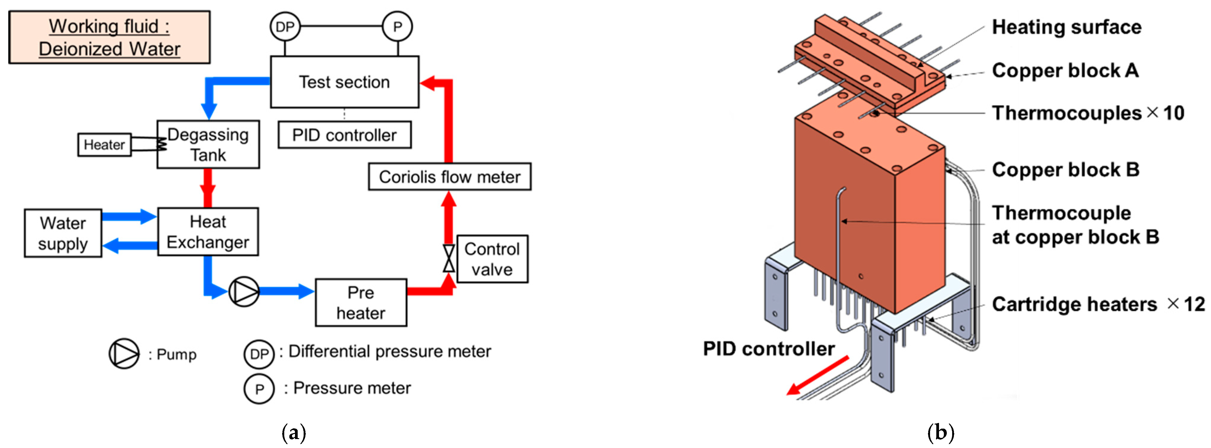
A schematic diagram of the experimental apparatus is shown in Figure 1a. Deionized water was used as the working fluid, and a degassing tank with a capacity of 40 L was used to store the water. A heat exchanger was installed just after the degassing tank to reduce the working fluid temperature. After around 2 h of degassing, a magnetic pump “IWAKI” was activated to provide the water flow. The mass flow was measured using an Oval Coriolis flowmeter and regulated with a control valve. The heating section is shown in Figure 1b. Copper block A and copper block B were assembled, cartridge heaters were used to heat copper block B, and one K-type thermocouple was inserted on copper block B to measure the temperature. A detailed explanation of the test section is given in the next section. The temperature of copper block A was controlled by a proportional integral derivate (PID) controller; thus, the test section was set to the desired heat flux and wall superheat. The copper block temperature was set from 120 °C and increased in steps of 40 °C. When the copper block reached 600 °C the experiment was stopped to avoid damages to the experimental equipment; in particular, the copper block. The upper part of the test section was covered by a polycarbonate lid, and the flow aspect was observed and recorded using a fast speed camera “Fastcam mini AX50” under 5000 fps and a shutter speed of 1/50,000. In the present experiments, the porous thickness, mass flux, and inlet subcooling were used as the parameters, as shown in Table 1, and each effect was discussed.
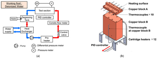
Figure 1.
Schematic of the experimental apparatus. (a) Schematic of experimental apparatus; (b) assembly of heating section.

Table 1.
Experimental condition.
2.2. Test Section and Measurement of Thermal Physical Properties
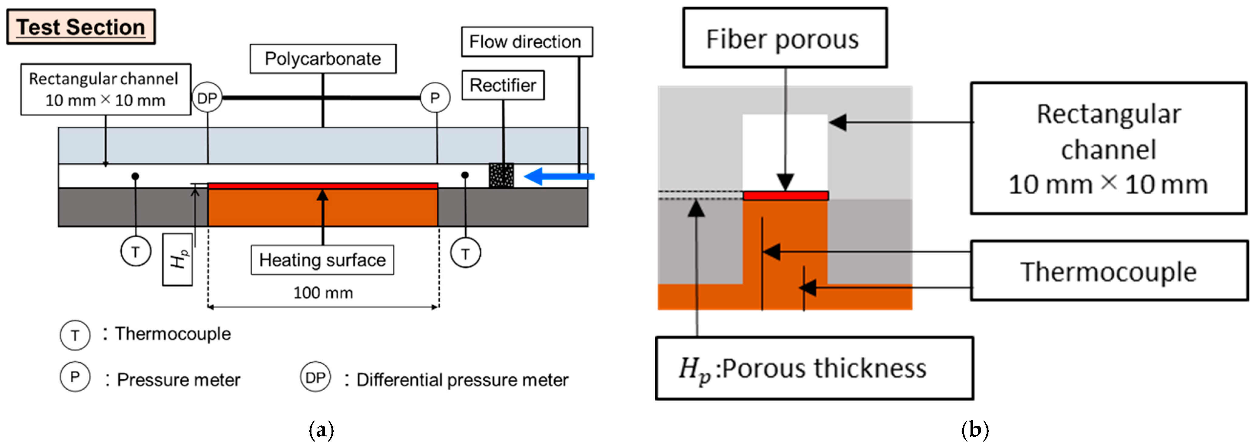
A uniform temperature field was created for the working fluid when it passed through the aluminum rectifier installed in the inlet part of the test section and then it flowed into the heating section as shown in Figure 2a. The pressure and temperature were measured in the inlet and outlet parts of the heating section. The physical properties of the working fluid were calculated using the software Refprop ver. 9.1 [28]. The channel was a square of 10 mm × 10 mm and the length of the heating section was 100 mm. As shown in Figure 2b, the heating surface was located on the lower part of the flow channel and covered by the polycarbonate to avoid heat loss.
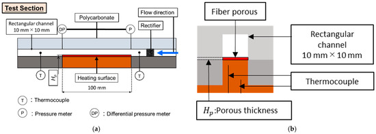
Figure 2.
Schematic of test section. (a) Front view; (b) side view.
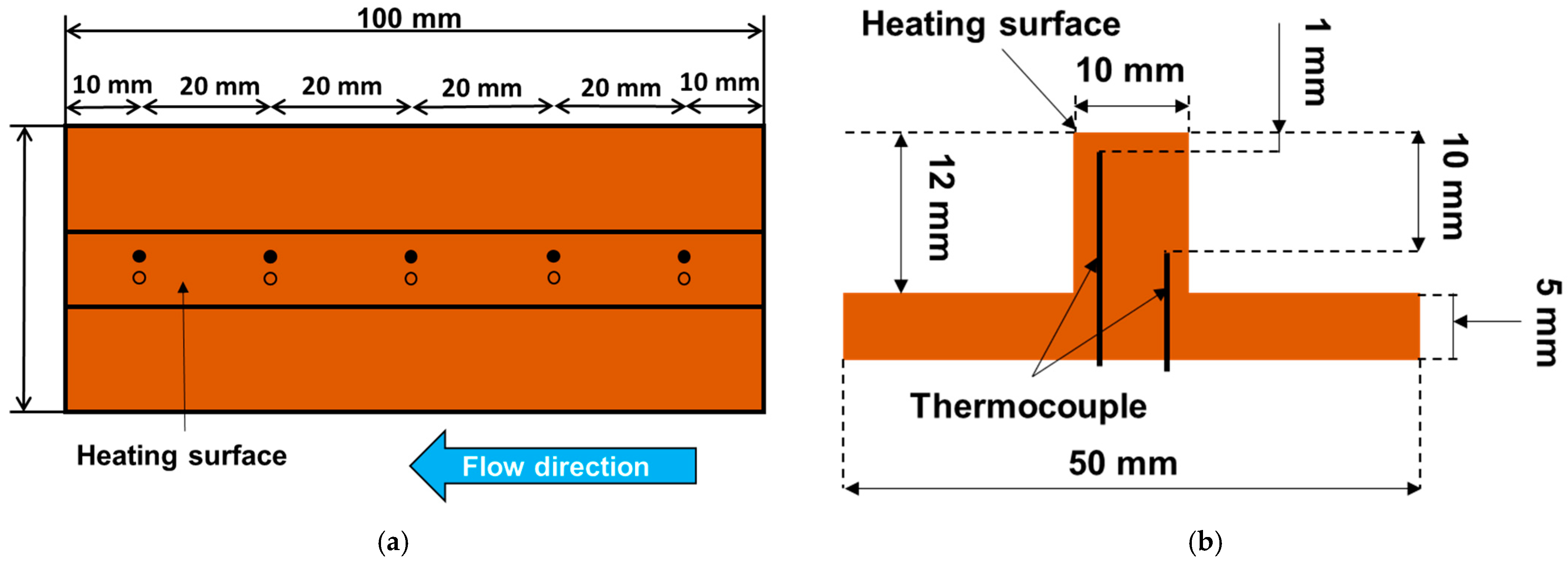
Figure 3a shows a top view of copper block A, which had a heat transfer surface of 10 mm × 100 mm. Ten thermocouples were divided into five groups of two thermocouples, and each group was inserted into copper block A. The five groups were located at (10, 30, 50, 70, and 90 mm) in the flow direction from the inlet part of the heating surface, respectively. Figure 3b shows the distribution of each pair of thermocouples; the distance between them was 9 mm, and the distances to the heating surface were 1 and 10 mm, respectively.
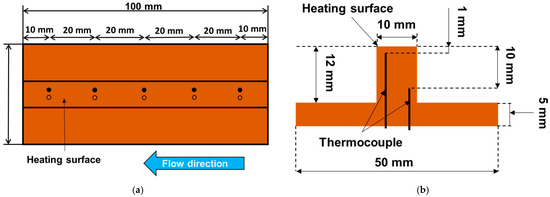
Figure 3.
Schematic of copper block A. (a) Top view; (b) side view.
The heat flux at each location was calculated using Fourier’s law Equation (1). The average of each measurement point was taken as the total amount of heat flux.
2.3. High-Porosity Sintered Fiber
The selected porous material in this study was copper, the same material as the heat transfer surface. It had a complex shape with copper fibers 0.06 mm diameter intertwined with each other. As shown in Figure 4a,b, the porous fiber was attached to the heat transfer surface, and the contact resistance can be neglected as they are sintered together. The porosity of the fiber metal was 86%; thus, the pressure drop was relatively small. The porosity was selected at 86% because this was the highest porosity level reached with the sintered manufacturing process in this research. The heat transfer also presents an enhancement, because metal fiber increases the heat transfer area. In addition, the micropores on the porous body promote bubble formation and the departure rates due to a reduction in the surface tension between the water and the heating surface.

Figure 4.
High-porosity sintered fiber metal. (a) Porous heating surface; (b) enlarged view of the porous material.
2.4. Uncertainly Analysis
The errors for each of the major measuring instruments are shown in Table 2. Two types of thermocouples were used to measure the temperature. The thermocouple to measure the fluid temperature had a zero-contacting point and was tested to have a measurement error of 0.05 K. The ten thermocouples used to measure copper block A in the test section were not tested, and the measurement error was 0.2 K. The measurement results showed that there was an error of 0.02 mm in the depth of the hole in copper block A.

Table 2.
Uncertainly values of the important parameters.
Thus, the heat flux was calculated with the following equation.
where k is the thermal conductivity, T2 − T1 is the differential temperature between the upper and lower thermocouples and δ is the distance between these thermocouples. The uncertainty of the heat flux is evaluated as follows:
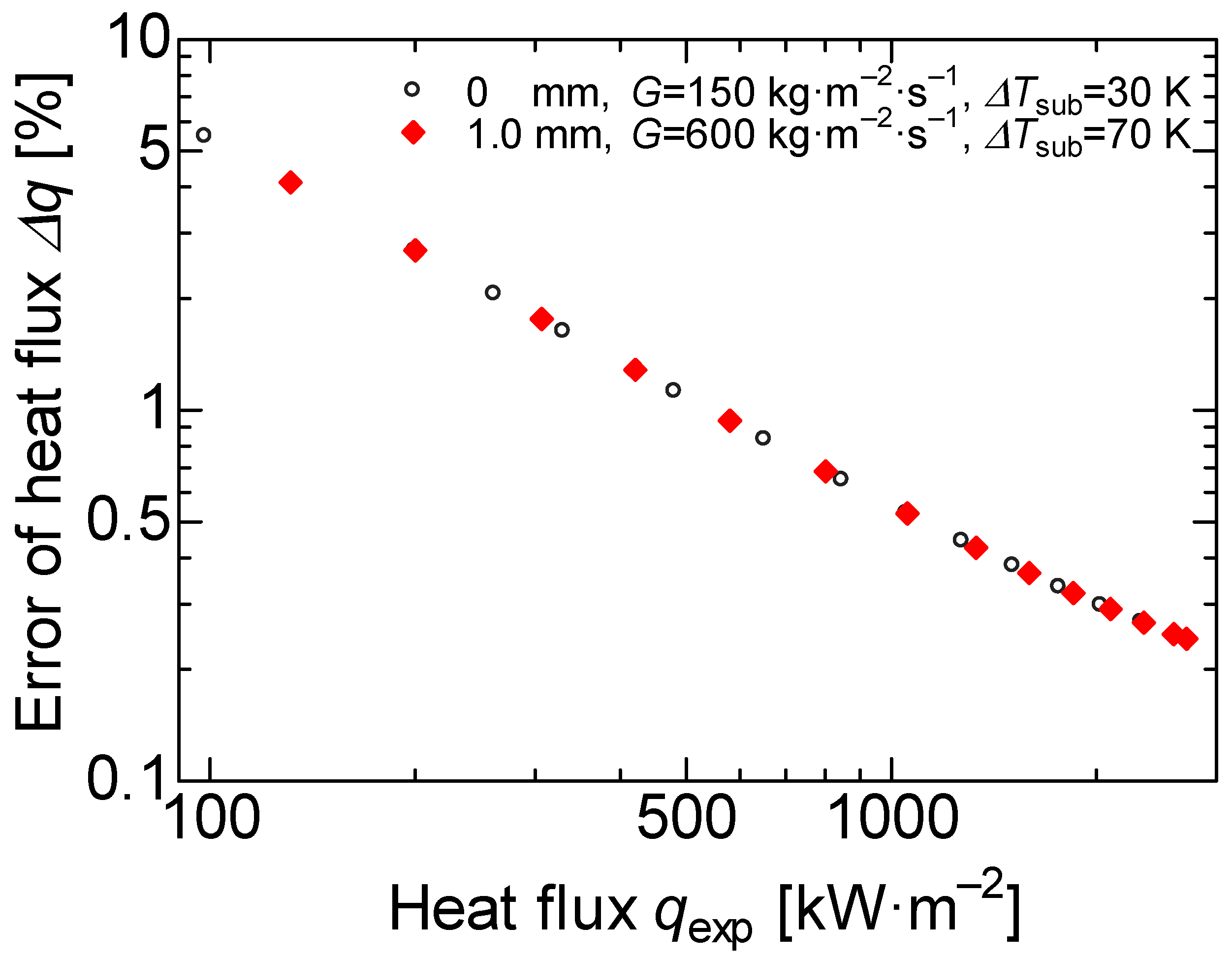
In Figure 5, the errors of each heat flux are plotted for 0 and 1 mm thickness heat transfer surfaces in comparison with the experimental results. The heat flux error was about 3% at the 200 kW·m−2; however, the heat flux error was less than 1% at a heat flux higher than 500 kW·m−2.
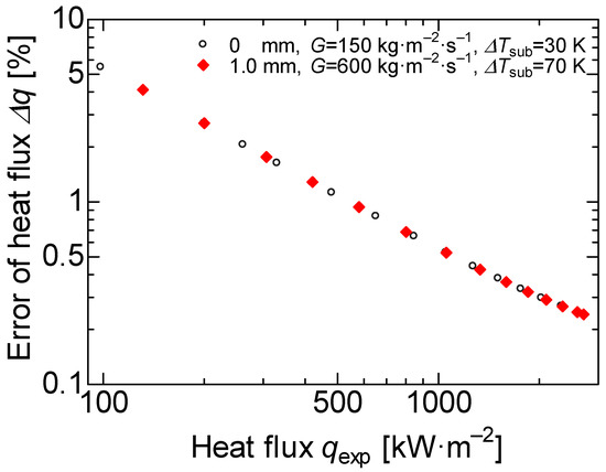
Figure 5.
Uncertainty of heat flux.
3. Results and Discussion
3.1. Comparison of Butterworth’s Correlation for the Bare Surface
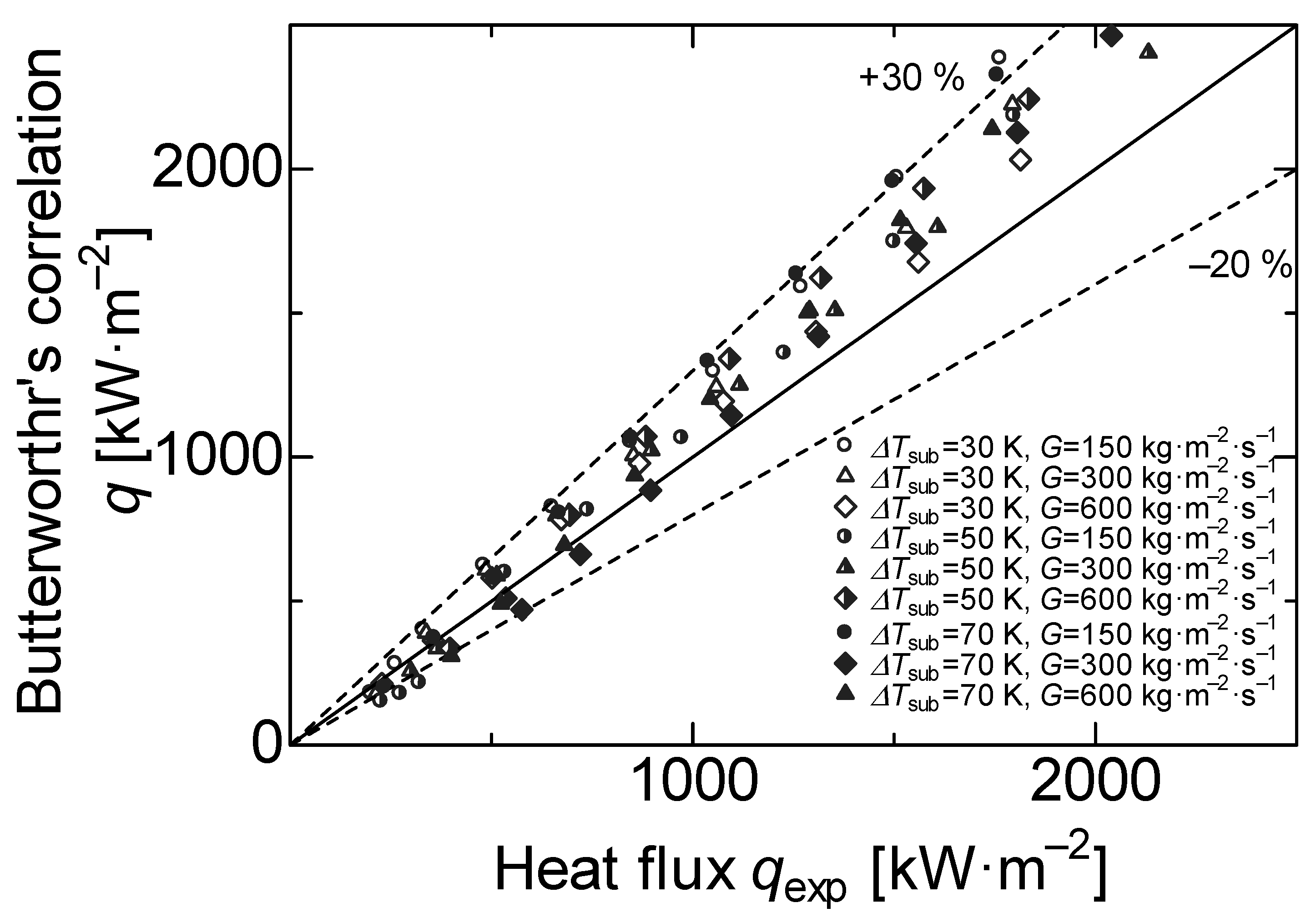
The experimental data were compared with Butterworth’s correlation for subcooled flow boiling heat transfer [25,29,30]. Butterworth et al. extended Chen’s correlation [31] and applied it to subcooled flow boiling [32]. Chen’s correlation considers the effects on the forced convection (heat flux corresponding to the single-phase) and the nucleate boiling (heat flux corresponding to the two-phases) on a superposition model, expressed as follows.
The supersession factor S and correlation factor can be calculated by the following equations.
In this experiment, we assumed that Φ = 1 for the subcooled flow boiling due to the vapor quality x < 0.1.
Thus, the total amount of the heat flux from Equation (1) can be calculated by the forced convection on the single-phase term , and the nuclear boiling term on the two phases heat flux term defined as follows.
The heat transfer coefficient of nucleate boiling is given by Foster–Zuber’s correlation [33].
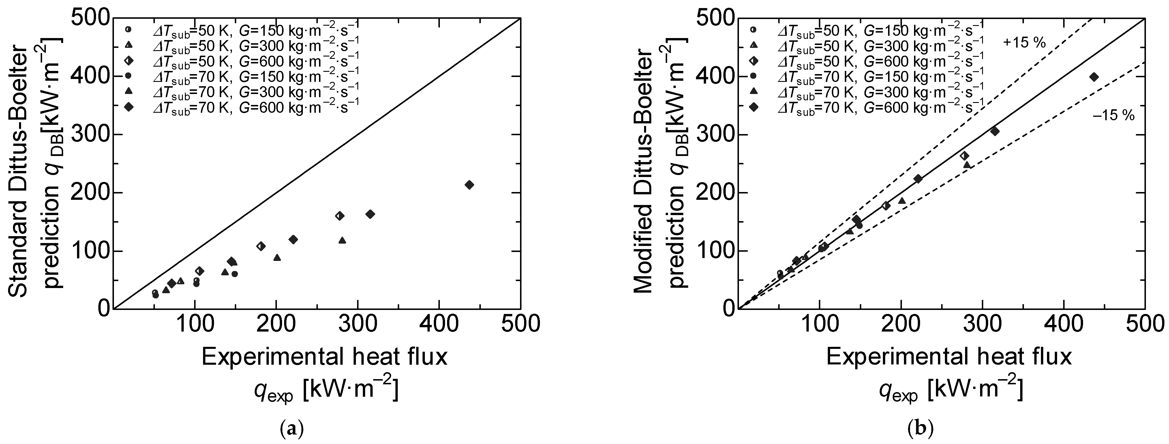
The heat transfer coefficient of forced convection is usually calculated using the Dittus–Boelter correlation. For the present research, the experimental heat flux on the single-phase was obtained with Equation (2), and the temperature measured by the thermocouples. In addition, we considered the single-phase when the . Figure 6a shows the comparison between the Dittus–Boelter correlation and the experimental data corresponding to the bare surface, and there was a decrease between the experimental heat flux and predicted heat flux. The experimental heat flux corresponding to the bare surface was around 50% lower than the predicted using Dittus–Boelter. This effect is due to the correlation considering a circular heated channel. Shiyang et al. [26] and Maria et al. [34] performed experiments using a rectangular channel heated on only one of its faces. The results show a considerable error in comparison with the Dittus–Boelter correlation. Shiyang [26] proposed modifying the correlation for the one heated face square channels computing a linear regression. After performing the linear regression, the heat transfer coefficient of forced convection is defined as follows:
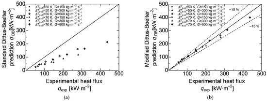
Figure 6.
Comparison between the experimental and predicted data. (a) Comparison to standard Dittus–Boelter correlation in the region of single phase heat transfer; (b) comparison to modified Dittus–Boelter correlation in the region of single phase heat transfer.
In Figure 6b, the heat flux calculated by the modified Dittus–Boelter’s correlation and the experimental heat flux corresponding to the bare surface is plotted. The coefficient of determination was 0.9522, which implies a high correlation. Figure 7 shows the comparison between the experimental heat flux corresponding to the bare surface and Butterworth’s correlation in Equation (4). Here, the experimental heat flux data were between 10% and were 30% lower than this correlation. The reduction in the heat flux is attributed to the oxidation effects, as the heat transfer surface was sufficiently oxidized by performing approximately 10 heating experiments beforehand to obtain stable data. Therefore, these values are slightly lower than those of the formulas due to the deterioration of the heat transfer performance caused by oxidation.
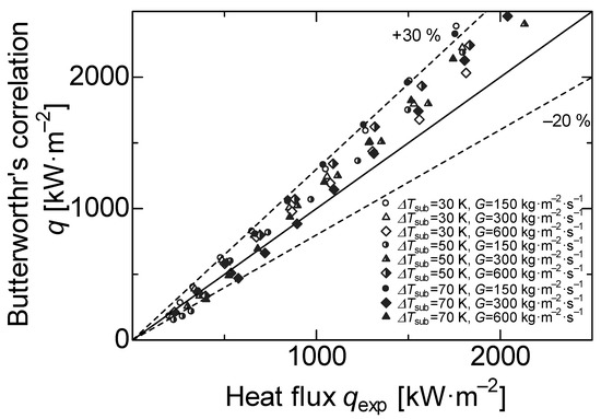
Figure 7.
Comparison between the experimental and Butterworth’s correlation.
3.2. Effect of High-Porosity Sintered Fibrous Metal
3.2.1. Effect of Porous Thickness and Boiling Curve
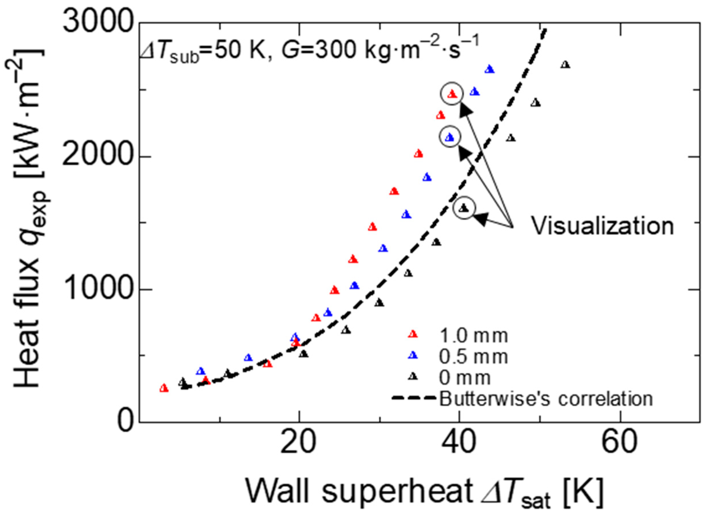
Figure 8 shows the boiling curve of the bare and porous surface at a subcooled temperature of 50 K and mass flux of 300 kg·m−2·s−1. We found that was no significant difference between porous and bare surfaces in the region where forced convection heat transfer was dominant; however, around = 20 K, where the bubble formation became intense and nucleate boiling heat transfer became dominant, the heat flux of the porous surface was improved in comparison to the bare surface at the same wall superheat degree. In addition, Figure 8 shows the heat flux at the same wall superheat, and the heat flux increased at higher porous thickness. The heat flux on porous surfaces with a thickness of 1 and 0.5 mm increased by 60% and 40%, respectively, compared to the bare surface at = 40 K. For the same heat flux at q = 1000 kW·m−2, the wall superheat was reduced to around 5 and 10 K for the 0.5 and 1 mm porous thickness, respectively, in comparison with the bare surface.
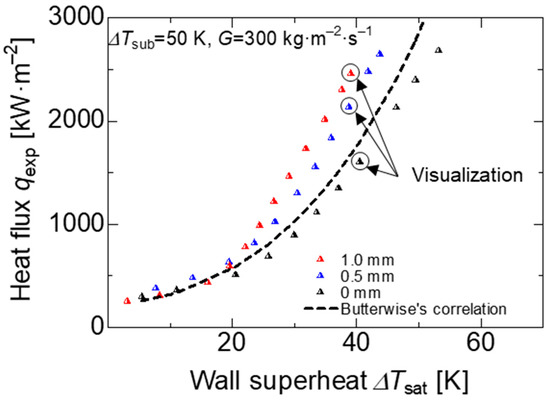
Figure 8.
Boiling curve on all heating surfaces at the subcooled temperature = 50 K and mass flux = 300 kg·m−2·s−1.
In the forced convection and transition regions, the effect of the porous body was minimal on the heat flux performance; however, in the nucleated boiling region, the porous body effect was evidently higher. The enhancement is mainly attributed to three effects: (I) the bubble dynamics, the bubble formation and departure rates increased, as shown in Figure 9a–c; (II) the cavitation sites increased due to the micro-pores formed by the random distribution of the copper fibers; (III) wettability promoted an easier water supply between the surface area and the bubbles.

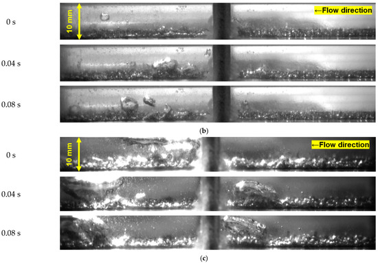
Figure 9.
Visualization of the heating surfaces at the subcooled temperature = 50 K, mass flux = 300 kg·m−2·s−1 and = 40 K. (a) Visualization of the flow pattern on a bare surface at the subcooled temperature = 50 K, mass flux = 300 kg·m−2·s−1 and = 40 K; (b) visualization of the flow pattern on a 0.5 mm porous surface at the subcooled temperature = 50 K, mass flux = 300 kg·m−2·s−1 and = 40 K; (c) visualization of the flow pattern on a 1.0 mm porous surface at the subcooled temperature = 50 K, mass flux = 300 kg·m−2·s−1 and = 40 K.
Figure 9 shows the subcooled flow boiling pattern of each heat transfer surface at a wall superheat of 40 K. As the thickness of the porous body increased, the amount and volume of the bubbles also increased. The bubbles were generated only on the surface of the heat transfer surface and quickly condensed on the case of bare surface 9a; however, the size of the bubbles increased and reached the middle of the channel at the 0.5 mm porous surface. In addition, bubbles reached the top of the channel on the 1 mm porous surface. This may be due to the increase in the number of cavities in the porous fibers, which results in nucleation boiling in more locations. We considered that the porous heat transfer surface showed high heat flux at the same wall heating degree, and the increase in the wall superheat was suppressed at the same heat flux.
3.2.2. Effect of Mass Flux
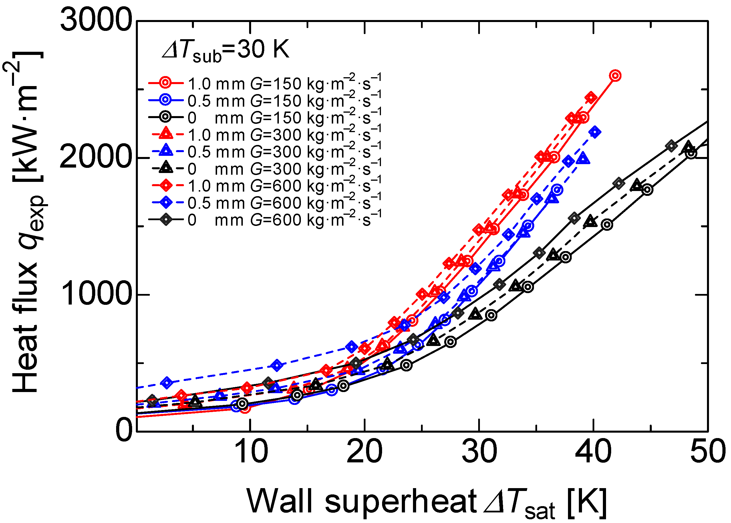
The boiling curve of the three different surfaces at mass flux G = 150, 300, and 600 kg·m−2·s−1 are shown in Figure 10. In general, the bare surface had the property that when the heat flux was constant in flowing subcooled boiling, the temperature boundary layer became thinner, and the onset nucleate boiling (ONB) shifted towards a higher wall heating degree as the mass flux increased [34]. The heat flux also increased as the mass flux increased. This effect is attributed to two main effects: the macro convection promoted by the working fluid motion and the layer evaporation between the heater wall and the water. However, independent of the mass flux, all the boiling curves converged at one point, called the transition to the fully developed boiling. Before this point, the effects of the macro convection became lower; however, the layer evaporation effect prevailed.
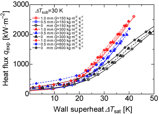
Figure 10.
Boiling curves for each surface at the subcooled temperature = 30 K.
In general, the heat flux, using porous surfaces, increased as the mass flux increased before the onset nucleate boiling (ONB); nevertheless, during the partial developed boiling the macro convection played an important role, and heat flux increased at a higher porous body thickness.
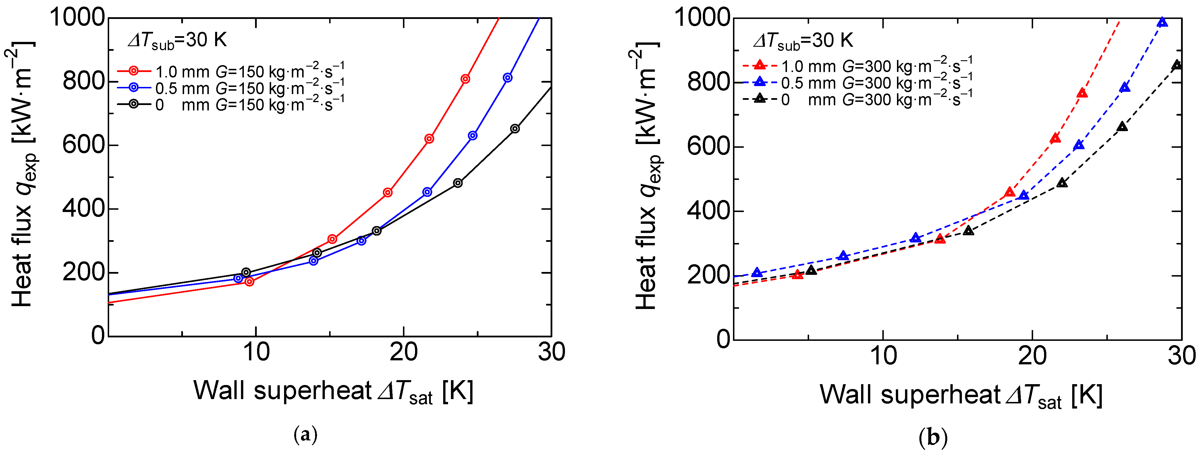
The enlarged boiling curve at mass flux G = 150 kg·m−2·s−1 is shown in Figure 11a. We found that there was a small variation in the heat flux when the wall superheat was 10 K or lower; however, the porous surfaces with 1.0 and 0.5 mm deviated from the slope of the forced convection at around 13 and 16 K, respectively. In other words, the wall superheat degree decreased as the porous body thickness increased. Figure 11b shows the boiling curve at the mass flux of 300 kg·m−2·s−1 where the deviation from the convection slope was around 15 and 18 K for the 1 and 0.5 mm porous thicknesses, respectively. The reason is attributed to the development of the thermal boundary layer. There are three main reasons for the difficulty in developing a thermal boundary layer. First is the turbulence effect caused by the porous body. This porous surface is installed on the bare surface, and it leads to stirring the working fluid near the heating surface. Second is the expanding heat transfer area. The porous metal is sintered to the heating surface as the same material, and the heat is easily transferred from the heating surface to the working fluid. Third is turbulence promotion by the bubbles. This porous surface has a higher number of cavity sites; thus, the generation and the evaporation of bubbles also increases. We considered that these effects cause turbulence in the thermal boundary layer compared to the bare heat-transfer surface and, therefore, the heat transfer is enhanced even at a low wall superheat.
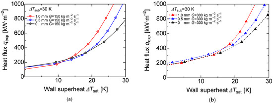
Figure 11.
Enlarged view of the boiling curves for each surface at the subcooled temperature = 30 K, (a) Enlarged view of the boiling curve for each surface at the subcooled temperature = 30 K, mass flux G = 150 kg·m−2·s−1. (b) Enlarged view of the boiling curve for each surface at the subcooled temperature = 30 K, mass flux G = 300 kg·m−2·s−1.
3.3. Critical Heat Flux
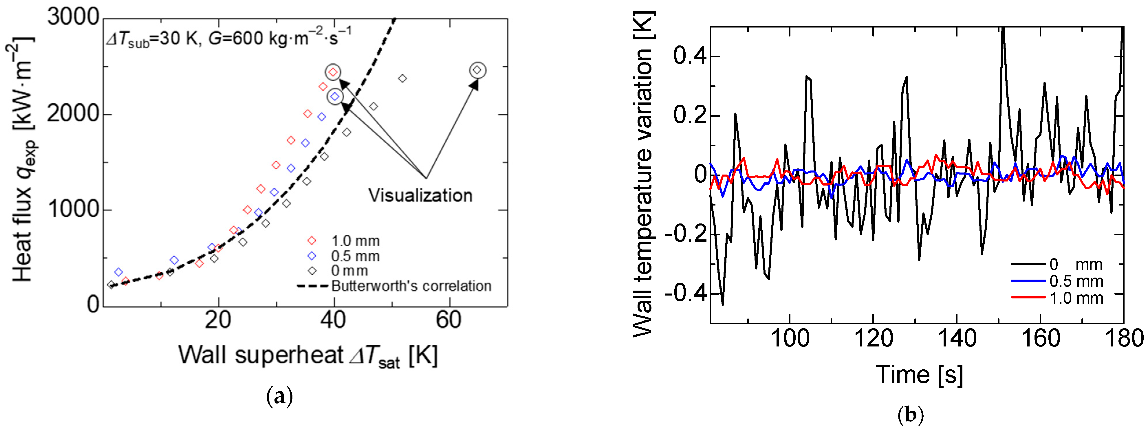
Due to the critical heat flux involving a phase change process, the analysis of this phenomenon is very complex and continues to be under study. However, researchers concluded that the CHF is directly related to the bubble formation on the solid surface, thus the importance of the surface modifications to enhance the CHF. Lainshun Wang [3] reported that the CHF enhancement is directly related to the water-supply ability through porous media. On the bare surface, bubbles are generated, coalesce, and finally, cover the heating area interrupting the water supply by promoting an abrupt increase in the wall temperature. On the other hand, in the case of the porous media, the distribution of the small fibers promotes a continuous water flow through the heating surface area, and the flow turbulence on the porous media promotes bubble formation and departure rate; thus, the porous media keeps the heating surface at lower temperatures compared with the bare surface. The heating surface is higher for the porous surface than for the bare surface, and, due to this fact, the heat rate increases at the same wall temperature, and the film boiling presents a delay. The surface tension and the wickability effects keep the heating surface at lower temperatures for the porous surface. The effect mentioned above enhances the CHF in the porous surface. In the particular case of the subcooled temperature of , 30 K and a mass flux of 600 kg·m−2·s−1, the critical heat flux was reached on the bare surface, around 50 K, the wall superheat increased rapidly to 63 K, and film boiling was observed during the boiling phenomenon, as shown in Figure 12a.
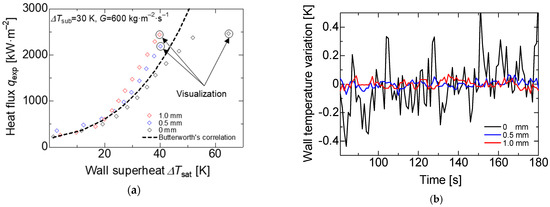
Figure 12.
The critical heat flux (CHF) or maximum heat flux. (a) Boiling curve at the subcooled temperature = 30 K and mass flux = 600 kg·m−2·s−1. (b) Variation of each surface at the heat flux q = 2500 kW·m−2.
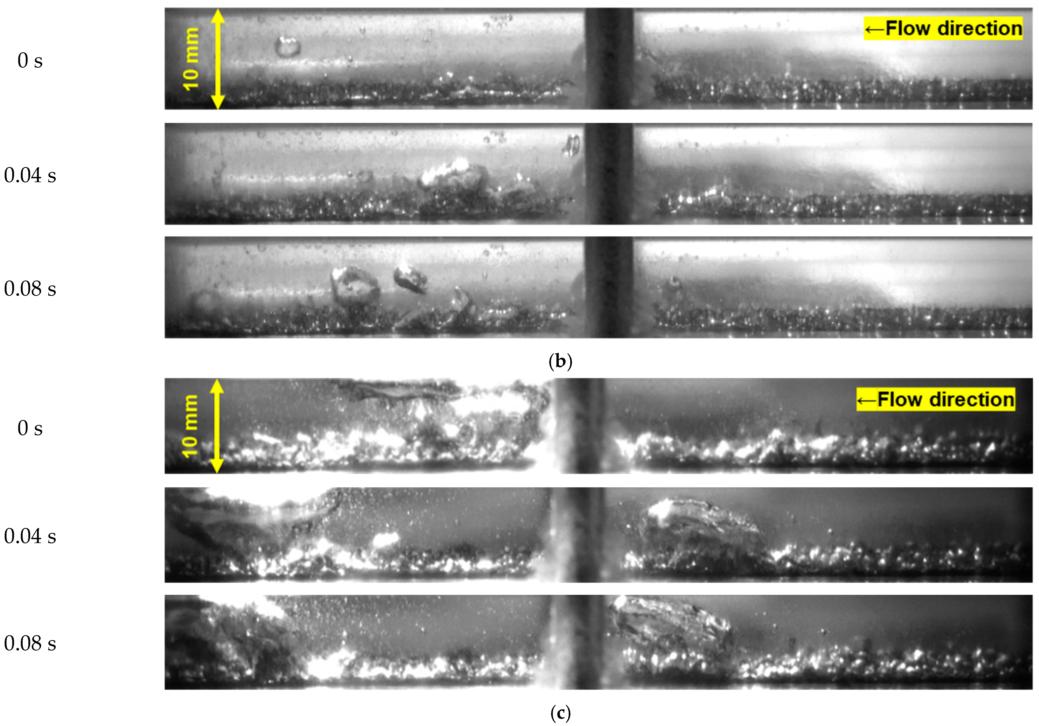
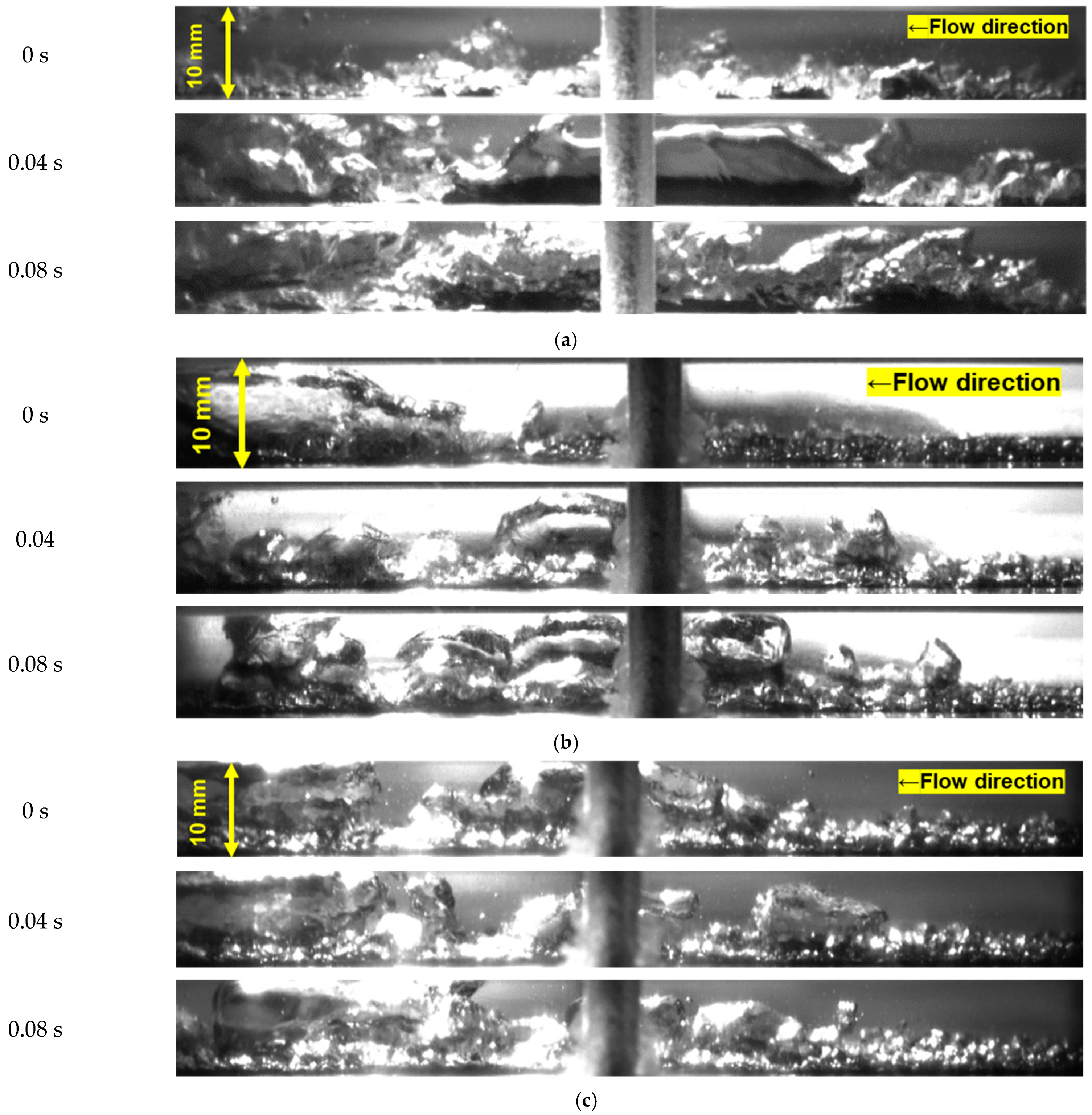
In addition, the wall temperature variations concerning the time are shown in Figure 12b. The variation on the bare surface wall temperature degree was between −0.4 and 0.4 K. However, for the porous surface case, the variation was barely 0.1 K. The bare surface reached the CHF, and the film boiling was observed on the heated wall, as shown in Figure 13a. Contrarily, using the high-porosity sintered porous metal, the CHF was not reached and the wall superheat stayed below the 40 K. The flow patterns are shown in Figure 13b,c for the 0.5 and 1 mm porous surfaces, respectively. On the porous surface, the burn out did not occur due to the constant water supply prompted by the bubble formation and the bubble departure rate was higher on the porous surfaces.
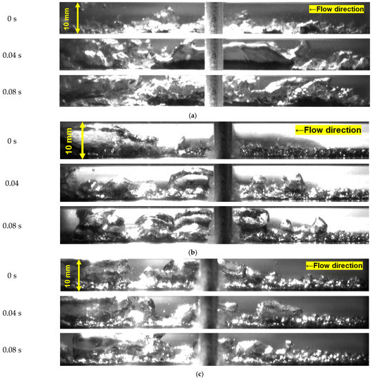
Figure 13.
Flow pattern of the different surfaces at the heat flux q = 2500 kW·m−2. (a) Visualization of the flow configuration on a bare surface at heat flux q = 2500 kW·m−2. (b) Visualization of the flow configuration on a 0.5 mm porous surface at heat flux q = 2500 kW·m−2. (c) Visualization of the flow configuration on a 1.0 mm porous surface at heat flux q = 2500 kW·m−2.
4. Conclusions
The present research reports on the heat transfer enhancement under the subcooling flow boiling using a high-porosity sintered fiber attached to the surface. Two different porous surface thicknesses (1 and 0.5 mm) and one bare surface were tested. The same experimental conditions for the three cases and the same flow channel were used for all the cases. After our analysis of the experimental results, our conclusions are presented.
- The effect of the porous surface on the heat flux was almost marginal on the single-phase region; however, after the onset nucleate boiling (ONB), the influence of the porous surface is important. At the same wall superheat (40 K), the heat flux on the bare surface was around 1600 kW·m−2; on the other hand, using the porous surface, the heat flux was around 2500 kW·m−2, which represents an enhancement of around 56%. At the same wall superheat (2000 kW·m−2), the wall superheat was around 48 K and around 36 K for the bare surface and the porous surface, respectively; in other words, a reduction of around 12 K on the wall superheat.
- At a higher mass flux and higher porous thickness, the heat flux was higher, and the wall superheat degree was lower. Thus, the ONB shifted to a higher wall heat flux. At the higher porous thickness, the bubble formation rate and departure rate increased.
- Using high sintered fiber as a passive method to promote bubble formation and departure increases the heat flux in comparison with the bare surface. The wall temperature degree variation was more stable using the porous surface. In addition, the wall superheat degree was reduced, avoiding burnout on the surface.
Author Contributions
Data curation, Y.O., E.S.G. and K.E.; Funding acquisition, K.E.; Investigation, Y.O., E.S.G. and K.E.; Project administration, K.E.; Visualization, Y.O. and E.S.G.; Writing—original draft, Y.O.; Writing—review & editing, K.E. All authors have read and agreed to the published version of the manuscript.
Funding
This research received no external funding.
Institutional Review Board Statement
Not applicable.
Informed Consent Statement
Not applicable.
Data Availability Statement
Data openly available in a public repository that issues datasets with DOIs.
Acknowledgments
We would also like to recognize the following researchers: Kenji Orito, Toshihiro Zushi, Kenji Takita, and Toshihiko Saiwai, who are affiliated with the Mitsubishi Materials Corporation.
Conflicts of Interest
The authors declare no conflict of interest.
References
- Kandlikar, S.G. Heat Transfer Characteristics in Partial Boiling, Fully Developed Boiling, and Significant Void Flow Regions of Subcooled Flow Boiling. J. Heat Transf. 1998, 120, 395–401. [Google Scholar] [CrossRef]
- Chen, X.; Xia, X.; Sun, C.; Yan, X. Transient thermal analysis of the coupled radiative and convective heat transfer in a porous filled tube exchanger at high temperatures. J. Heat Transf. 2017, 108, 2472–2480. [Google Scholar] [CrossRef]
- Wang, L.; Khan, A.R.; Erkan, N.; Gong, H.; Okamoto, K. Critical heat flux enhancement on a downward face using porous honeycomb plate in saturated flow boiling. Int. J. Heat Mass Transf. 2017, 109, 454–461. [Google Scholar] [CrossRef]
- Deng, D.; Wan, W.; Shao, H.; Tang, Y.; Feng, J.; Zeng, J. Effects of operation parameters on flow boiling characteristics of heat sink cooling systems with reentrant porous microchannels. Energy Convers. Manag. 2015, 96, 340–351. [Google Scholar] [CrossRef]
- Dewangan, A.K.; Kumar, A.; Kumar, R. Nucleate boiling of pure and quasi-azeotropic refrigerants from copper coated surfaces. Appl. Eng. 2016, 94, 395–403. [Google Scholar] [CrossRef]
- Li, C.; Peterson, G.P. Evaporation/Boiling in Thin Capillary Wicks (II)—Effects of Volumetric Porosity and Mesh Size. J. Heat Transf. 2006, 128, 1320–1328. [Google Scholar] [CrossRef]
- Sarangi, S.; Weibel, J.A.; Garimella, S.V. Effect of particle size on surface-coating enhancement of pool boiling heat transfer. Int. J. Heat Mass Transf. 2015, 81, 103–113. [Google Scholar] [CrossRef]
- Sahu, R.P.; Sinha-Ray, S.; Sinha-Ray, S.; Yarin, A.L. Pool boiling of Novec 7300 and self-rewetting fluids on electrically-assisted supersonically solution-blown, copper-plated nanofibers. Int. J. Heat Mass Transf. 2016, 95, 83–93. [Google Scholar]
- Pialago, E.J.T.; Kwon, O.K.; Jin, J.S.; Park, C.W. Nucleate pool boiling of R134a on cold sprayed Cu-CNT SiC and Cu-CNT-AIN composite coatings. Appl. Therm. Eng. 2016, 103, 648–694. [Google Scholar]
- El-Genk, M.S. Nucleate Boiling Enhancements on Porous Graphite and Microporous and Macro–Finned Copper Surfaces. Heat Transf. Eng. 2012, 33, 175–204. [Google Scholar]
- Furberg, R.; Palm, B. Boiling heat transfer on a dendritic and micro-porous surface in R134a and FC-72. Appl. Eng. 2011, 31, 3595–3603. [Google Scholar] [CrossRef]
- Ali, A.F.; El-Genk, M.S. Effect of inclination on saturation boiling of PF-5060 dielectric liquid on 80- and 137-l thick copper micro-porous surfaces. Int. J. Therm. Sci. 2012, 53, 42–48. [Google Scholar] [CrossRef]
- Ujereh, S.; Fisher, T.; Mudawar, I. Effects of carbon nanotube arrays on nucleate pool boiling. Int. J. Heat Mass Transf. 2007, 50, 4023–4038. [Google Scholar] [CrossRef]
- Bian, H.; Kurwitz, C.; Sun, Z.; Cheng, K.; Chen, K. Enhanced nucleate boiling on 3D-printed micro-porous struc-tured surface. Appl. Therm. Eng. 2018, 141, 422–434. [Google Scholar] [CrossRef]
- Lin, L.; Kedzierski, M.A. Review of low-GWP refrigerant pool boiling heat transfer on enhanced surfaces. Int. J. Heat Mass Transf. 2019, 131, 1279–1303. [Google Scholar] [CrossRef]
- Qin, J.; Chen, Q.; Yang, C.; Huang, Y. Research process on property and application of metal porous materials. J. Alloy. Compd. 2016, 654, 39–44. [Google Scholar] [CrossRef]
- Manetti, L.L.; Moita, A.S.O.H.; De Souza, R.R.; Cardoso, E.M. Effect of copper foam thickness on pool boiling heat transfer of HFE-7100. Int. J. Heat Mass Transf. 2020, 152, 119547. [Google Scholar] [CrossRef]
- Calmidi, V.V.; Mahajan, R.L. Forced Convection in High Porosity Metal Foams. J. Heat Transf. 2000, 122, 557–565. [Google Scholar] [CrossRef]
- Mori, S.; Okuyama, K. Enhancement of the critical heat flux in saturated pool boiling using honeycomb porous media. Int. J. Multiph. Flow 2009, 35, 946–951. [Google Scholar] [CrossRef]
- Cooke, D.; Kandlikar, S.G. Effect of open microchannel geometry on pool boiling enhancement. Int. J. Heat Mass Transf. 2012, 55, 1004–1013. [Google Scholar] [CrossRef]
- Deng, D.; Wan, W.; Feng, J.; Huang, Q.; Qin, Y.; Xie, Y. Comparative experimental study on pool boiling performance of porous coating and solid structures with reentrant channels. Appl. Eng. 2016, 107, 420–430. [Google Scholar] [CrossRef]
- Liter, S.G.; Kaviany, M. Pool-boiling CHF enhancement by modulated porous-layer coating: Theory and experiment. Int. J. Heat Mass Transf. 2001, 44, 4287–4311. [Google Scholar] [CrossRef]
- Hao, W.; Wang, T.; Jiang, Y.; Guo, C.; Guo, C. Pool boiling heat transfer on deformable structures made of shape-memory-alloys. Int. J. Heat Mass Transf. 2017, 112, 236–247. [Google Scholar] [CrossRef]
- Jayaramu, P.; Gedupudi, S.; Das, S.K. Influence of heating surface characteristics on flow boiling in a copper microchannel: Experimental investigation and assessment of correlations. Int. J. Heat Mass Transf. 2019, 128, 290–318. [Google Scholar] [CrossRef]
- Steiner, H.; Kobor, A.; Gebhard, L. A wall heat transfer model for subcooled boiling flow. Int. J. Heat Mass Transf. 2005, 48, 4161–4173. [Google Scholar]
- Hua, S.; Huang, R.; Li, Z.; Zhou, P. Experimental study on the heat transfer characteristics of subcooled flow boiling with cast iron heating surface. Appl. Eng. 2015, 77, 180–191. [Google Scholar]
- Leong, K.C.; Ho, J.Y.; Wong, K.K. A critical review of pool and flow boiling heat transfer of dielectric fluids on enhancement surfaces. Appl. Therm. Eng. 2017, 112, 999–1019. [Google Scholar] [CrossRef]
- Lemmon, E.W.; Huber, M.L.; McLinden, M.O. NIST Standard Reference Database 23: Reference Fluid Thermodynamic and Transport Properties-REFPROP; Version 9.1; NIST Publications: Gaithersburg, MD, USA, 2013.
- Fang, X.; Yuan, Y.; Xu, A.; Tian, L.; Wu, Q. Review of correlations for subcooled flow boiling heat transfer and assessment of their applicability to water. Fusion Eng. Des. 2017, 122, 52–63. [Google Scholar] [CrossRef]
- Collier, J.G.; Thome, J.R. Convective Boiling and Condensation, 3rd ed.; Oxford University Press: Oxford, UK, 1994. [Google Scholar]
- Chen, J.C. Correlation for Boiling Heat Transfer to Saturated Fluids in Convective Flow. Ind. Eng. Chem. Process. Des. Dev. 1966, 5, 322–329. [Google Scholar]
- Butterworth, D. The Correlation of Cross Flow Pressure Data by Means of a Permeability Concept; Report AERE-R9435; UKAEA Atomic Energy Research Establishment: Didcot, UK, 1979.
- Forster, H.K.; Zuber, N. Dynamics of vapor bubbles and boiling heat transfer. AIChE J. 1955, 1, 531–535. [Google Scholar] [CrossRef]
- Vlachou, M.C.; Lioumbas, J.S.; David, K.; Chasapis, D.; Karapantsios, T. Effect of channel height and mass flux on highly subcooled horizontal flow boiling. Exp. Fluid Sci. 2017, 83, 157–168. [Google Scholar] [CrossRef]
Publisher’s Note: MDPI stays neutral with regard to jurisdictional claims in published maps and institutional affiliations. |
© 2021 by the authors. Licensee MDPI, Basel, Switzerland. This article is an open access article distributed under the terms and conditions of the Creative Commons Attribution (CC BY) license (http://creativecommons.org/licenses/by/4.0/).

