Abstract
This paper proposes a control algorithm for a hybrid power electronic AC/DC converter for prosumer applications operating under deep phase current asymmetry. The proposed system allows independent control of active and reactive power for each phase of the power converter without current pulsation on the DC link connected to an energy store. The system and its algorithm are based on a three-phase converter in four-wire topology (AC/DC 3p-4w) with two dual-active bridge (DC/DC) converters, interfaced with a supercapacitor and an energy storage. The control algorithm tests were carried out in a Hardware in the Loop environment. Obtained results indicate that operation with deep unbalances and powers of opposite signs in individual phases leads to current oscillations in the DC link. This phenomenon significantly limits energy storage utilization due to safety and durability reasons. The proposed algorithm significantly reduces the level of pulsation in the DC link which increases safety and reduces strain on lithium-ion storage technology, enabling their application in four-wire converter applications.
1. Introduction
There is currently an exponentially growing number of receiving devices, based on impulse power supplies in every household. From the point of view of an energy supply system it is seen as an unbalanced, non-linear load. On the other hand, increasing numbers of energy consumers become energy producers, so called prosumers, due to installation of renewable energy sources. In worst case scenario, energy users would consume a large amount of energy in one phase, and produce energy in another phase (when using single-phase PV inverter) (Figure 1). These two combined factors can lead to an unbalance in phase currents, which in turn causes power transformers to operate in non-nominal conditions, leading to more losses and increasing risk of faults in the grid. Additionally, a current asymmetry can cause a voltage asymmetry at local terminals, which will then propagate into the utility grid. The simplest method of solving the above problem is reducing the grid voltage asymmetry by reducing the available power of single-phase or three-phase PV inverters in the function of the phase voltage. This method is inherently loss characterised, so other solutions should be applied to solve the mentioned problem. There are known methods for solving the grid balancing problem, mainly based on Dual Vector Current Control methods and three-phase four wire inverters [1,2,3]; however, these methods can only operate with an unbalanced grid, while still generating balanced currents and they have no means to compensate the grid voltage unbalance
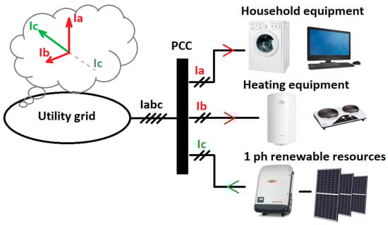
Figure 1.
Energy user worst case scenario.
Currently, researchers focus on methods utilizing prosumer converters to locally balance the power flow in the grid. One of the promising methods is using a four-wire, three-phase converter with a lithium-ion energy storage and independent power control for each phase of the system [4,5]. This method allows for the best flexibility at the cost of increased degradation of the energy store. The current asymmetry on the output of the four-wire power converter causes large pulsation on DC link, which affects operation of the electrochemical energy storage [6,7]. Depending on the inverter mode, the energy storage would be charged or discharged, and power delivered to the grid can be approximated as power of the DC link. Instantaneous power in DC link can be described as sum of output powers of three phases.
where: p3f—power in DC link, Vk—phase voltage, Ik—phase current, φvk—phase voltage angle, φik—phase current angle.
In a balanced scenario, where the inverter generates symmetric currents, sum of time variant components of three phases equals zero, and there is no pulsation present. However, when asymmetry is introduced in the sum of time variant components does not equal zero, and resulting power pulsation is transferred to DC link. Frequency of this pulsation is double the frequency of main grid voltage component.
This situation is undesirable, as it adds AC component to current in DC link, which in turn transfers into AC component in current in the electrochemical energy storage. Such scenario causes the energy storage to switch from charging to discharging with frequency of 100 Hz, which causes unwanted heating of the battery cells. The lithium-ion energy storage is necessary in this system, as power delivered to the system will not always be equal to power drawn from the system across three phases, and eventually DC link would be drained or overcharged, resulting in system shutdown. Additionally, a factor not considered in this paper that can improve the system is a renewable energy source, which can keep the DC link charged when the source is operational. The main aim of this work is the evaluation of a new topology and a control algorithm, which can generate asymmetric currents and at the same time maintain low level of a DC link current pulsation, acceptable for the lithium-ion energy storages.
2. Four-Wire Hybrid Converter with Multi-Resonant Regulators
A four-wire hybrid converter is comprised of an electrochemical energy storage, a capacitor bank, two isolated DC/DC converters and a three-phase, four-wire bidirectional converter (Figure 2). Both DC/DC converters are based on two H-bridges connected through a medium frequency transformer (DAB—dual active bridge topology) [8,9]. The converter connected to energy storage serves as a charging controller [10], while the one connected to the capacitor bank is meant to take over any non-DC current, which would normally transfer to the battery. The four-wire bidirectional converter is a 3 level T-NPC topology-based converter [11,12], with an independent control of active and reactive power in each phase. It can be viewed as three independent single-phase converters, connected to common N-wire. An additional DC/DC converter with the capacitor bank takes compensates the DC link current pulsation. Effectively, in response to this pulsation, the DC/DC converter produces a current of the same amplitude but opposite phase than the pulsation. Since capacitors do not generate losses when under AC loads, they can take over any pulsation that would negatively affect the lithium-ion energy storage. Compensating of this current could be achieved by different means; however, all those are worse compared to the dual-active bridge topology and capacitor bank. Passive compensation would require an increase by several times in capacitance to have a noticeable effect on the system, and it would draw a significant inrush current. A buck-boost converter has limited voltage gain, worse efficiency and dynamics than DAB converter. An LLC converter has worse dynamics and bidirectionality requires a specific design and is often limited. An interesting concept is used in electric vehicles, where resonant circuits are used to produce sinewaves to warm the batteries in cold environment—a similar solution could be applied in this system; however, due to low resonant frequency, large capacitors and inductors would be required. Since the dual active bridge topology is naturally bidirectional and fully symmetric, it is an optimal choice for this application.
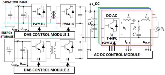
Figure 2.
Three-phase, four wire converter system with energy storage and capacitor bank, where: L1, L2, R, C—passive elements of inverter output LCL sin filter, Ucap, icap—current and voltage of bank capacitor, Ustor, istor—current and voltage of energy storage, ug—utility grid voltage, ig_a, ug_a—phase a current and voltage, 3L T-NPC—three-level T-type converter, H- full bridge, PWMA—phase a control signal.
Voltage-oriented control algorithms are limited when it comes to compensating the grid asymmetry, and it is impossible to achieve different power flow direction in each of the phases using those algorithms. This forces different approach: a separate control algorithm for each of the phases of the three level-four wire inverter. With separate current references for each of the phases it is possible to achieve asymmetric operation of the inverter and balance the grid on local scale. The control of active and reactive power on the output of the four-wire converter requires correct and reliable synchronization with the grid [13]. In order to provide an accurate signal, even in presence of a significant voltage asymmetry, a DDSRF-PLL (Decoupled Double Synchronous Reference Frame—Phase Locked Loop) synchronization algorithm is used (Figure 3) [14,15,16]. A sawtooth signal produced by DDSRF-PLL is used to create sine and cosine wave reference signals for both active and reactive current and those values are then multiplied by amplitude references (iref_active_a, iref_reactive_a) provided by a higher-level controller, like grid operator. Those two signals are then added together and the result is a sinewave with amplitude and phase required to force power flow in specific direction. This reference wave is compared against feedback. An error of the converter current is passed to a proportional-resonant regulator (PR) [17]. The regulator is tuned so its resonant frequency matches the main frequency component of the power grid. Adding more proportional-resonant controllers in parallel with the first one, and tuning them for specific harmonics allows additional harmonic compensation, improving the overall THDi of the system [18,19].
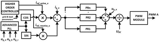
Figure 3.
Control algorithm for single phase of three-phase four wire converter, where: iref_active_a, iref_reactive_a—references for active and reactive current components, ug_a, ug_b, ug_c—instantaneous phase voltages, UDC—DC inverter link voltage.
The transfer function of this controller is described by the following equation:
where: —proportional controller gain, —resonant controller gain, —resonant span parameter —controller resonant pulsation.
This system allows independent control over the power flow in each of the phases, enabling asymmetric operation of the inverter. The laboratory setup to evaluate this operation is presented in Figure 4. The consequence of this is pulsation in the DC link occurring when operating with asymmetric currents, as shown in Figure 5, Figure 6, Figure 7 and Figure 8. Both AC and DC components of the DC link current are affected by asymmetry, causing undesirable states for the energy storage. In an extreme case, the energy storage affected by an AC current pulsation, increases internal energy losses above the permitted limit. This is potentially dangerous situation because energy storage can overheat and combust.
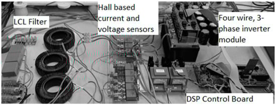
Figure 4.
Three-phase, four wire converter module used during laboratory tests.
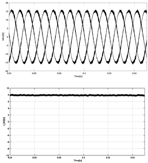
Figure 5.
Three phase current and DC link current during symmetric operation with 15 A active current inverter mode (experimental results, I_DC measured at istor point in Figure 1).

Figure 6.
Three phase current and DC link current during asymmetric operation with 15 A active current on phases: A and B, 4 A reactive current on phase C of inverter (experimental results, I_DC measured at istor point in Figure 1).
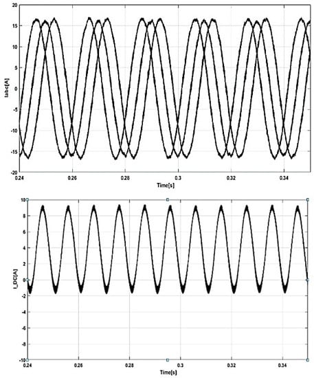
Figure 7.
Three phase current and DC link current during asymmetric operation with 15 A active current on phases: A, B and C—two phases operate as inverter and one phase operates as rectifier (experimental results, I_DC measured at istor point in Figure 1).
The level of Pulsation in the DC link current can be directly linked to the current in neutral wire; in fact, there is a linear relationship (Figure 9).
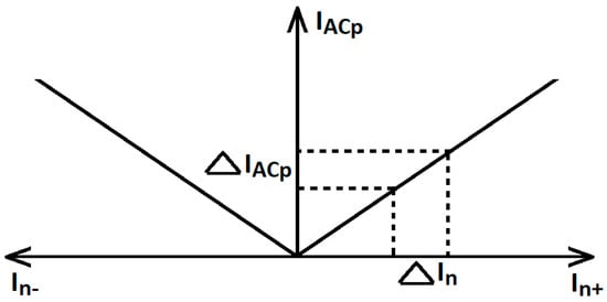
Figure 9.
Alternating current pulsation on the DC link as a function of converter neutral wire current, where: In+,In−—neutral wire current, IACp—magnitude of current pulsation on DC link.
The magnitude of the AC component of the DC link current (IAC_DCLink) as a function of the magnitude of the AC component of the neutral wire current (In) can be described as:
where: V1—phase rms voltage, VDC—DC link voltage.
Instantaneous value of AC component, based on Equations (1) and (3) can be described as:
where φn—phase of neutral wire current.
3. Reduction of DC Link Current Pulsation
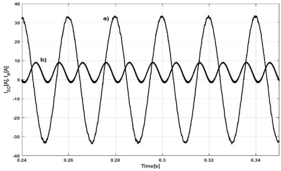
It is impossible to eliminate the DC link current pulsation using passive means: authors investigated if increasing a DC link capacity would resolve the problem: in simulation, only 20–30% reduction was achieved and by means of increasing the capacity several times, making it inapplicable (Figure 10). As such, an active compensation is required.
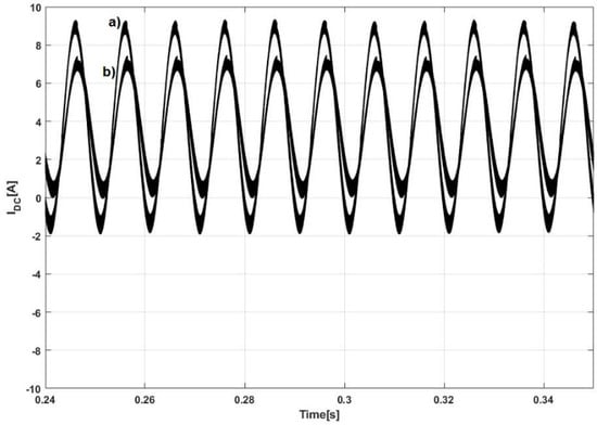
Figure 10.
DC current pulsation with DC link capacity 5 mF (a) and 25 mF (b) (simulation results).
Dual active bridge topology is an attractive solution for this application due to its high dynamics and easy transition between charging and discharging mode [20,21]. A control algorithm is quite similar to the one driving the four-wire inverter (Figure 3). This time; however, the DC link current is used as feedback, and the reference signal is zero (Figure 11). The proportional resonant filter is tuned for frequency of 100 Hz. Additional filters can be connected in parallel, tuned for harmonics of 100 Hz (200, 300, 400 Hz). Furthermore, any residual DC component from the signal is removed, and the result is passed directly to phase control module. A mathematical description of this algorithm is presented in Equation (4).
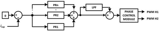
Figure 11.
Control algorithm for compensating the DC link pulsating current (DAB Control Module 1).
The resulting system naturally damps any DC components, and amplifies components of 100 Hz frequency and its harmonics (Figure 12).
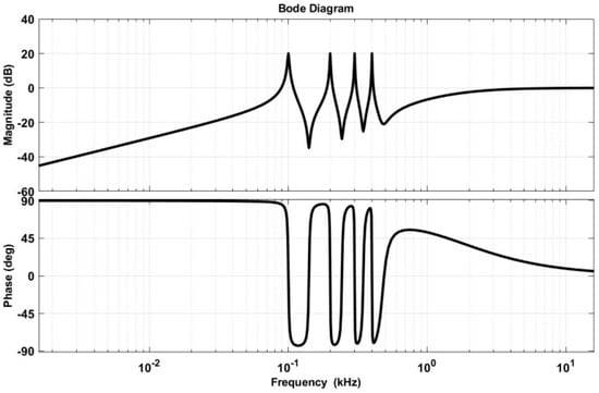
Figure 12.
Bode plot of control algorithm for compensating the DC link pulsating current.
The proposed algorithm effectively removes AC components from the DC link of the power inverter. Additionally, because of the high rejection of DC components from the control circuit it is possible to avoid overcharging or completely discharging the bank of capacitors. During laboratory tests, authors did not observe any aforementioned phenomena, and concluded, that additional voltage control loop, or overvoltage protection is not required. Additional harmonic compensators are redundant in case when power converter operates in steady-state grid-tied applications, but are highly recommended when the power inverter operates in transient states or operates in island mode with highly nonlinear loads.
4. Implementation of the Algorithm in Inverter System
In order to evaluate properties of the AC current compensation algorithm, the laboratory stand was built. First, current pulsation was evaluated in a system with no compensation, as presented in (Figure 4). A battery charge-discharge curve was programmed into a bidirectional DC voltage supply ITECH-IT6012C. The voltage supply was connected to the three-phase four-wire inverter through the DC/DC converter using DAB topology. Based on the results, the authors decided to add an identical DC/DC converter in parallel, connected to the capacitor bank. Parameters of the final test bench are presented in Table 1.

Table 1.
Table of main converters parameters.
Before testing was conducted, the capacitor bank was pre-charged to 60 V, to ensure stable startup of the DC/DC converter. The DC link current was observed using a Tektronix MSO5034B oscilloscope. Data were logged and then processed using Matlab/Simulink. Figure 11 presents the results of the system operation. The system was run first without the AC current compensation, then the additional DC/DC converter was turned on. The results show initial current spike, caused by a converter launch, but it drops in less than 10 ms. Afterwards, the system operation is stable. Further, frequency analysis of the signal was performed. THD presented in Figure 13 is THDi value in relation to the DC component. In the case without active AC current compensation THDi in relation to DC component was 155.89%. With active compensation THDi drops to 4.3%. AC component observed on power inverter DC link drops by 97%. This compensation comes at a cost of pulsation appearing in capacitor bank (Figure 14), but this situation is plausible, as the electrochemical energy storage is prevented from heating up.
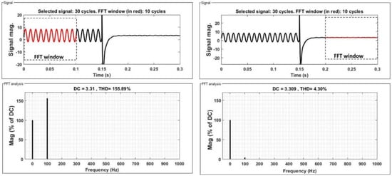
Figure 13.
The DC Link current pulsation and FFT analysis for cases without (before Time = 0.15 s) and with (after Time = 0.15 s) proposed compensation algorithm operation (experimental results, measured at istor point in Figure 1).
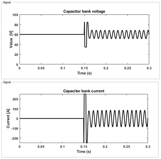
Figure 14.
The capacitor bank current and voltage pulsation for cases without (before Time = 0.15 s) and with (after Time = 0.15 s) proposed compensation algorithm operation (experimental results, current measured at i_cap point in Figure 1).
5. Conclusions
This paper presented a novel algorithm for compensating an AC component of a DC link current in a grid-tied inverter operating with a renewable energy source and an energy storage. It was shown, that asymmetrical phase currents and resulting current flow in neutral wire cause the AC component to appear in the DC link current. Since applications with a local grid compensation are becoming more attractive for the grid operators, this current flow cannot be suppressed without preventing the local compensation. Since the AC component is undesirable for an electrochemical storage, authors propose a system of active compensation of the AC component in the DC link current. It is shown, that the proposed method can reduce AC oscillations by 97%, virtually eliminating the problem. The downsides of this solution include the increase in volume and the cost of the system implementing this algorithm, as well as requirement for fast signal processors, as the algorithm is based on multiple resonant compensators and demands rapid acquisition and rapid signal processing. However, the resulting system possesses desirable qualities for the grid operators. Further research in this area would include operation under transient states, island operation, and operation with heavily non-linear loads.
Author Contributions
Conceptualization, D.Z. and K.F.; methodology, D.Z.; software, D.Z. and K.F.; validation, D.Z. and K.F.; formal analysis, D.Z.; investigation, D.Z.; data curation, D.Z.; writing—original draft preparation, D.Z. and K.F.; writing—review and editing, D.Z. and K.F.; supervision, D.Z.; funding acquisition, D.Z. All authors have read and agreed to the published version of the manuscript.
Funding
This research was funded by Polish National Centre for Research and Development, grant number POIR.04.01.02-00-0007/17. The APC was funded by Lublin University of Technology.
Institutional Review Board Statement
Not applicable.
Informed Consent Statement
Not applicable.
Data Availability Statement
Data sharing not applicable.
Conflicts of Interest
The authors declare no conflict of interests.
References
- Kein, H.C.; Yun, S.L.; Jianhui, W.; Philip, T.; Ezra, M.; Stella, M. Voltage Unbalance Mitigation in Low Voltage Distribution Networks with Photovoltaic Systems. J. Electron. Sci. Technol. 2012, 10, 1. [Google Scholar]
- Piasecki, S.; Jasiński, M.; Milicua, A. Brief view on Control of Grid-Interfacing AC-DC-AC Converter and Active Filter under Unbalanced and Distorted Voltage Conditions. Int. J. Comput. Math. Electr. Electron. Eng. 2011, 30, 351–373. [Google Scholar] [CrossRef]
- Muljadi, E.; McKenna, H.E. Power quality issues in a hybrid power system. IEEE Trans. Ind. Appl. 2002, 38, 803–809. [Google Scholar] [CrossRef]
- Dai, M.; Marwali, J.J.M.N.; Keyhani, A. A three-phase four-wire inverter control technique for a single distributed generation unit in island mode. IEEE Trans. Power Electron. 2008, 23, 322–331. [Google Scholar] [CrossRef]
- Segui-Chilet, S.; Gimeno-Sales, F.; Orts, S.; Alcaniz, M.; Masot, R. Selective shunt active power compensator in four wire electrical systems using symmetrical components. Electr. Power Compon. Syst. 2007, 35, 97–118. [Google Scholar] [CrossRef]
- Ahmed, O.A.; Bleijs, J.A.M. An overview of DC–DC converter topologies for fuel cell-ultracapacitor hybrid distribution system. Renew. Sustain. Energy Rev. 2015, 42, 609–626. [Google Scholar] [CrossRef]
- Mamadou, B.C.; Hamid, G.; Frederic, G.; Alain, B. DC/DC Converter Design for Supercapacitor and Battery Power Management in Hybrid Vehicle Applications—Polynomial Control Strategy. IEEE Trans. Ind. Electron. 2010, 57, 587–597. [Google Scholar]
- Innoue, S.; Akagi, H.A. Bidirectional DC-DC Converter for an Energy Storage System with Galvanic Isolation. IEEE Trans. Power Electron. 2007, 22, 2299–2306. [Google Scholar] [CrossRef]
- Barlik, R.; Nowak, M.; Grzejszczak, P. Power transfer analysis in a single phase dual active bridge. Bull. Pol. Acad. Sci. 2013, 61, 809–828. [Google Scholar] [CrossRef]
- Jeong, D.K.; Kim, H.S.; Baek, J.W.; Kim, J.Y.; Kim, H.J. Dual Active Bridge converter for Energy Storage System in DC Microgrid. In Proceedings of the 2016 IEEE Transportation Electrification Conference and Expo, Asia-Pacific (ITEC Asia-Pacific), Busan, Korea, 1–4 June 2016; pp. 152–156. [Google Scholar]
- Schweizer, M.; Kolar, J.W. Design and Implementation of a Highly Efficient Three-Level T-Type Converter for Low-Voltage Applications. IEEE Trans. Power Electron. 2013, 28, 899–907. [Google Scholar] [CrossRef]
- Madasamy, P.; Suresh Kumar, V.; Sanjeevikumar, P. A Three-Phase Transformerless T-Type- NPC-MLI for Grid Connected PV Systems with Common-Mode Leakage Current Mitigation. Energies 2019, 12, 2434. [Google Scholar] [CrossRef]
- Blaabjerg, F.; Teodorescu, R.; Liserre, M.; Timbus, A.V. Overview of control and grid synchronization for distributed power generation systems. IEEE Trans. Ind. Electron. 2006, 53, 1398–1409. [Google Scholar] [CrossRef]
- Rodriguez, P.; Pou, J.; Bergras, J.; Candela, J.I.; Burgos, R.P.; Boroyevich, D. Decoupled double synchronous reference frame PLL for power converters control. IEEE Trans. Power Electron. 2007, 22, 584–592. [Google Scholar] [CrossRef]
- Silva, S.M.; Lopes, B.M.; Filho, B.J.C.; Campana, R.P.; Bosventura, W.C. Per-formance evaluation of PLL algorithms for single-phase grid-connected systems. IEEE Ind. Appl. Conf. 2004, 4, 3–7. [Google Scholar]
- Jarzyna, W. A survey of the synchronization process of synchronous generators and power electronic converters. Bull. Pol. Acad. Sci. 2019, 67, 1069–1083. [Google Scholar]
- Islam, S.; Zeb, K.; Din, W.; Khan, I. Design of a Proportional Resonant Controller with Resonant Harmonic Compensator and Fault Ride Trough Strategies for a Grid-Connected Photovoltaic System. Electronics 2018, 7, 451. [Google Scholar] [CrossRef]
- Daniel, Z.; Cyril, S.S. Design of PR current control with selective harmonic compensators using MATLAB. J. Electr. Syst. Inf. Technol. 2017, 4, 347–358. [Google Scholar]
- Teodorescu, R.; Blaabjerg, F.; Liserre, M.; Loh, P.C. Proportional-resonant con-trollers and filters for grid-connected voltage-source converters. IEEE Proc. Electr. Power Appl. 2006, 153, 750–762. [Google Scholar] [CrossRef]
- Krismer, F. Modeling and Optimization of Bidirectional Dual Active Bridge DC-DC Converter Topologies. Ph.D. Thesis, Eidgenössische Technische Hochschule, Zürich, Switzerland, 2010. [Google Scholar]
- Demetriades, G.D.; Nee, H. Dynamic Modeling of the Dual-Active Bridge Topology for High-Power Applications. In Proceedings of the IEEE Power Electronics Specialists Conference, Rhodes, Greece, 15–19 June 2008. [Google Scholar]


Publisher’s Note: MDPI stays neutral with regard to jurisdictional claims in published maps and institutional affiliations. |
© 2021 by the authors. Licensee MDPI, Basel, Switzerland. This article is an open access article distributed under the terms and conditions of the Creative Commons Attribution (CC BY) license (http://creativecommons.org/licenses/by/4.0/).