Abstract
Water hammer wave is widely applied to test hydraulic components in various areas. A new hydraulic high-pressure impulse generator is presented in this paper in order to provide the standard water hammer wave for long-term usage. A combination of a sleeve and a rotary spool was used to build the impulse generator, and a booster piston was applied to amplify the output pressure. Mathematical models were established using commercial software, and a prototype and a test rig were built based on the simulation results. The experimental results for both single wave and repeated periods show the feasibility of the new design and indicate that the new hydraulic high-pressure impulse generator can be used for long-time impulse tests.
1. Introduction
The failure of hydraulic components can have serious consequences, especially when advanced hydraulic systems applied in the aeronautics and astronautics areas involve a complex system structure for meeting the strict standards of compactness [1]. Hydraulic pressure impulses are known as a critical cause of damage to hydraulic components [2]. These impulses are generated by an instantaneous compression of the oil, for instance, at the moment of pumping oil through a volumetric pump [3,4,5], opening/closing valve orifices, or changing the flow direction of oil [6]. Since the hydraulic pressure impulse is obviously undesirable but inevitable in any hydraulic component, it is reasonable, particularly in industries, to perform impulse tests on randomly selected samples to guarantee the reliability of an entire batch of products.
The American Society of Automotive Engineers (SAE) and ISO consider the water hammer wave or the hydraulic shock as one main pressure impulse wave standard for the impulse testing of hydraulic hoses, tubing, and fitting assemblies [7,8,9]. The standard pressure/time curves of the wave are shown in Figure 1. Since the produced trace of the dynamic pressure impulse should be mandatorily confined within the shaded area shown in Figure 1 [8], the development of the pressure impulse generator is increasingly important for achieving an acceptable hydraulic pressure impulse output.
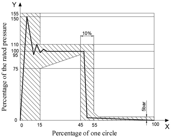
Figure 1.
Standard water hammer wave.
Further, the build-up standard of the pressure impulse generator proposed by the SAE [10] is widely used by researchers. Generally, pressure impulse generators can be divided into two types based on their controllability and adjustability characteristics. The first type focuses on realizing the produced pressure impulse as close as possible to the hydraulic impulse occurring under actual working conditions. A proportional valve or a servo valve driven by an electromechanical actuator can help establish a close-loop feedback system to obtain the required output pressure impulse signals. Song et al. set up hydraulic-impulse-testing equipment with an oil pump controlled by a solenoid servo valve and modeled the transfer function of the whole system [11]. Man et al. designed a hydraulic-impulse-testing system with a second-stage servo valve and used the pressure difference feedback signal to achieve accurate output control [12]. In another study, Man et al. used accumulators for energy regeneration to reduce the energy consumption of the testing system for long-term usage [13]. Recently, Filo et al. used a flow control valve to establish a pressure pulse generator [14]; by employing a fuzzy logic controller, they simultaneously obtained the required pressure square wave and a continuously square flow rate.
Adopting a different approach, other research groups focused on providing acceptable pressure impulse waves with different frequencies for long-duration industrial tests such as reliability and performance tests. Unlike the approaches listed in the previous paragraph, these groups attempted to extend the lifetime of the pressure impulse generator and reduce the manufacturing cost. For instance, it is hard to guarantee that the sevro/proportional valve would have a longer life time than the tested hydraulic component when a close-loop feedback system is applied for generating a million pressure impulse waves in a reliability test; further, there exists the concern of the potential high expenditure of the valve. Therefore, a simple and open-loop system is desirable. To simplify the structure, Chen used a profiled cam to drive a single-rod hydraulic cylinder to generate the pressure impulse wave; the rotational speed of the cam indicates the frequency of the output signal [15]. Drop-weight method too has been commonly applied to develop impulse pressure generators [16,17]; however, this method can hardly provide even a rough water hammer wave. Theimer and Kolle designed a hydraulic pulse valve with a rotary spool and improved the sleeve to achieve longer wear life and better performance; these features will can help establish an open-loop system that generates the required pressure impulse signals [18].
This paper proposes a new hydraulic impulse generator for long-time impulse tests under high pressure. The main part of the generator contains a rotary valve to produce the required pressure impulse wave by successively connecting different pressure sources and a pressure-boost cylinder to increase the output pressure to the aim level. A mathematical model was developed based on the design and working principle, and subsequently, a simulation analysis was performed. Finally, a prototype was manufactured and assembled for testing its feasibility.
2. Structure and Working Principles
The main architecture of the new hydraulic impulse generator, as shown in Figure 2, can be divided into two parts. The left part, which is considered as the booster part, comprises a left block (3) with an asymmetric booster piston (4) and a connecter (2) that is connected to the tested hydraulic component (1). The booster piston partitions the interior into four chambers with different functions. The high-pressure chamber (A) forms the inner space of the tested components and is filled with the hydraulic oil for transmitting the pressure signals. The withdraw chamber (B) is connected to the rated pressure source () and contributes to increasing the declining slope of pressure signals. The air chamber (C) is connected to the air, and the low-pressure chamber (D) filled with hydraulic oil is directly connected to the output of the impulse generator part, a rotary spool (8), and electro motor (10). The impulse generator part has a right block (6) with a sleeve (7) inside. The rotary spool is supported by two deep groove ball bearings and a thrust bearing for the axial force balance. The electro motor is solidly set on a motor base (9) to drive the rotary spool rotating in the sleeve. The setup of the sleeve and rotary spool is shown in Figure 3. Three pairs of windows are symmetrically set on the sleeve, and from left to right, they are sequentially but independently connected to the back pressure (), peak pressure source (), and rated pressure source (). Since a couple of rectangular slots is also symmetrically located on the rotary spool and connected to the central drilling as shown in Figure 2, each window is scanned by the slot when the spool is rotated using the electro motor. Thus, the pressure signals from three different sources are obtained by the slot and outputted into the low-pressure chamber through the throttle valve (5) twice per revolution. Meanwhile, several small oblique holes on the right side of the drilling connect the two sides of the rotary spool to reduce the axial hydraulic unbalancing force. Thereafter, the pressure impulse signal is amplified by means of the booster piston and transferred to the high-pressure chamber to produce the required pressure waves for the tested hydraulic components.
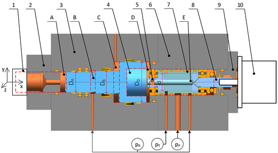
Figure 2.
Structure of the new hydraulic impulse generator. Here, 1 indicates the tested hydraulic components; 2, the connecter; 3, the left block; 4, the booster piston; 5, the throttle valve; 6, the right block; 7, the sleeve; 8, the rotary spool; 9, the motor base; 10, the electro motor. Further, A indicates the high-pressure chamber; B, the withdraw chamber; C, the air chamber; D, the low-pressure chamber; E, the inner space of the spool.
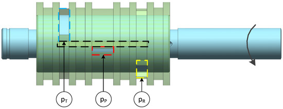
Figure 3.
Schematic assembling diagram of the sleeve and the spool. The blue rectangle represents the back pressure window; the red rectangle, the peak pressure window; the yellow rectangle, the rated pressure window; the dark rectangle, the slot on the rotary spool.
3. Mathematical Models
Since the impulse generator part and the booster part are connected, the low-pressure chamber plays a critical role in this device. Assuming that the booster piston is located at the right end of the stroke for the initialization, the low-pressure chamber has the minimum volume, and at the moment depicted in Figure 2, the rotary spool starts rotating. The instantaneous pressure in the chamber is governed by the following pressure build-up equation [19].
where is the instantaneous pressure in the low-pressure chamber; , the time since the rotation started; , the bulk modulus of the hydraulic oil; , the volume of the low-pressure chamber; , is the flow rate passing through the throttle valve as shown in Equation (4). Further, the volume of the low-pressure chamber and its time variation are shown in Equations (2) and (3), respectively.
where is the minimum volume of the low-pressure chamber; is the diameter of the right end of the booster piston as shown in Figure 2; is the stroke of the booster piston.
where is the orifice coefficient [19]; , the cross-sectional area of the throttle valve; , the oil density; , the pressure of the inner space of spool and can be described as follows.
where , , and are three flow rates related to the peak pressure source, rated pressure source, and back pressure, respectively, and is the volume of the inner space of the spool.
As seen in Figure 3 and Figure 4b, the inner space of spool can only be connected to one pressure source at any time, especially under the assumption of no leakage among the three pressure sources. Therefore, the three flow rates are directly determined by the cross-sectional areas and are given as shown in Equation (6a–c).
where , , and are the pressure values of the peak pressure source and rated pressure source and the back pressure, respectively. They are all considered as constants. , , and (Figure 4b), are the cross-sectional areas related to the three pressure sources. These areas are defined by the overlaps of the windows on the sleeve and the slots on the rotary spool as shown in Equation (7a–c).
where is in radians. Further, is the diameter of the spool; , , , , , , and are dimensions (see Figure 4); , , and are used to simplify the description.
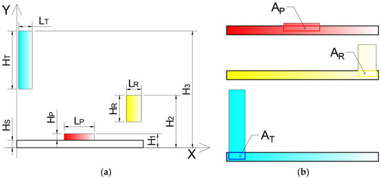
Figure 4.
Schematic of the windows on the sleeve and the slot on the rotary spool. (a) Half of the unfolding schematic (). (b) Schematics of the three cross-sectional areas.
Note that θ is considered as the product of time and the input rotational speed, . Therefore, the change in the cross-sectional areas can be expressed by substituting for from Equation (7).
Therefore, the instantaneous pressure in the low-pressure chamber, , can be calculated by substituting Equations (2)–(5) into Equation (1). Then, for the no-load condition, the force-balance equation of the booster piston is established through Newton’s second law and is shown in Equation (9).
where , , , and are the axial shadow areas of the chambers indicated by the subscripts. They are calculated using the corresponding diameters. Owing to the simplicity of this calculation, it is not repeated here. Further, , and are the pressures of the chambers indicated by the subscripts; is the rated pressure and is the atmospheric pressure; is the mass of the booster piston; is the viscosity damping coefficient.
The pressure build-up equation used for the instantaneous pressure in the high-pressure chamber, , can be seen as Equation (10) since this chamber is connected to the inner chamber of the tested hydraulic components without any flow.
where is the maximum volume of the high-pressure chamber:
As the output frequency of the impulse generator is twice per rotation, the relationship between the output frequency of the pressure wave, , and the input rotational speed, , is as shown in Equation (11).
4. Simulation Analysis
To investigate the feasibility of the design and to optimize same critical parameters, a mathematic model was established using commercial software. The Runge–Kutta method was employed to solve the partial differential equations. To obtain a water hammer output wave with 25 MPa rated pressure, a series simulation was performed by applying the parameters listed in Table 1 as the initial values.

Table 1.
Critical parameters.
For a water hammer wave, the rate of pressure rise is an important but hidden parameter among the parameters shown in Figure 1. According to the ISO standard [8], a water hammer wave should be at the range of 0.42–2.1 Mpa/ms. Since the proposed design uses a rotary valve to form the wave, the pressure is built-up rapidly as the window is opened. Therefore, the rate of increase in pressure may exceed the range that can be controlled by a throttle valve, as shown in Figure 2. The effects of changing the diameter of the throttle valve, , are shown in Figure 5. It is easy to conclude that diameters higher than the default value lead to unacceptable slopes. Both 1 and 0.7 mm diameters of the throttle valve result in smaller slopes, but the slopes become lower than the minimum rate at the end of the rises.
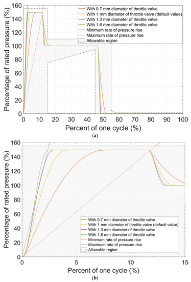
Figure 5.
Effect of different diameters of the throttle valve. (a) The complete, dimensionless figure. (b) Magnified view of a part of the figure shown in (a).
A notable difference between the default curve shown in Figure 5a and the standard curve shown in Figure 1 is in the form of the peak. The height of window P, , and the height of the slot, , are so large that the peak of the pressure curve is flattened. Figure 6 shows the results when both parameters are reduced simultaneously. Apparently, a smaller height corresponds to a sharper peak. However, reduction of either of the two parameters can cause a reduction of the wave’s duty cycle and the curve may exceed the tolerance range. This result implies that the height of window R, , should be increased.
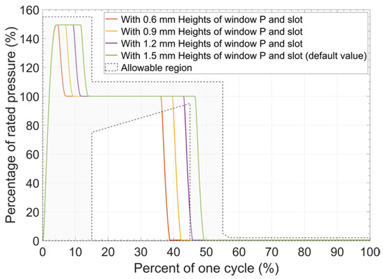
Figure 6.
Effect of various heights of window P and slot.
After a comprehensive consideration, a new table with the updated parameters was proposed in Table 2 listed in the next section, and the corresponding simulation result is shown in Figure 7.
Table 2.
Updated parameters.
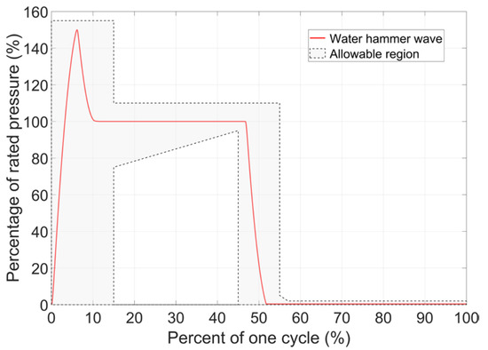
Figure 7.
Water hammer wave produced by using the optimized parameters.
Besides, before practical application, it is necessary to evaluate the influence of some unpredictable factors that can deform the ideal curve. For instance, because the hydraulic system can hardly be isolated from air, the hydraulic oil inevitably has dissolved air or even entrained air; the presence of air results in a drastic decrease in the bulk modulus [20,21]. The volume of the high-pressure chamber, , is related to the inner space of the tested hydraulic components. This inner space too should be studied well considering the lack of knowledge regarding inner spaces. The effects of different values of the bulk modulus and volume of the high-pressure chamber are shown in Figure 8a,b, respectively. An increase in either the bulk modulus or the volume of the high-pressure chamber leads to a decrease in the peak pressure and in the slopes of pressure rise. Therefore, considering the effects of different values of the bulk modulus, a strict exhaust procedure should be implemented after filling the hydraulic oil in to the system. Further, with regard to the unpredictable volume of the high-pressure chamber, it is highly recommended that the diameter of the throttle valve and the input peak pressure for each tested hydraulic component be customized.
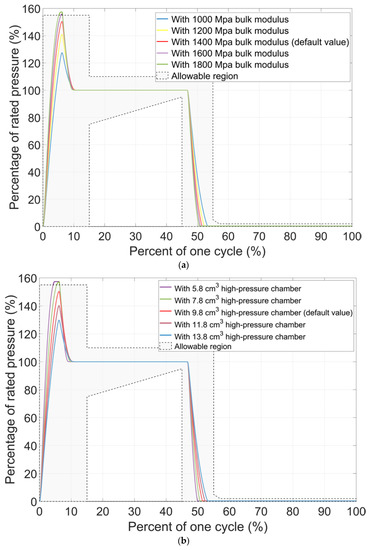
Figure 8.
Evaluation of the unpredictable factors. (a) Effect of different values of the bulk modulus. (b) Effect of different volumes of the high-pressure chamber.
5. Experimental Results
As shown in Figure 9a, the hydraulic system for the new hydraulic high-pressure impulse generator consists of an impulse generator designed considering all the parameters listed in Table 1 and Table 2, a gear pump and a relief valve to provide the input peak pressure, a flow-control valve to obtain a pressure drop, another relief valve to maintain the rated input pressure, and a pressurized tank to provide the back pressure. Two input pressure values are monitored by pressure gages, whereas the output pressure is observed and recorded by the pressure sensor which is set on the connecter part as in Figure 9b. The sampling frequency of the output pressure is 100 Hz as considered the long-duration application. The details of critical hydraulic components are listed in Table 3.
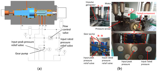
Figure 9.
Test rig of the new hydraulic high-pressure impulse generator. (a) Schematic of the hydraulic system for the test rig. (b) An overview of the test rig.
Table 3.
Details of the hydraulic components.
Before the start of the test, an exhaust procedure was performed, and the oil temperature was set at around 25 °C under constant room temperature and monitored by the temperature transducer on the tank. The motor was controlled to rotate at 30 rpm to obtain 1-Hz water hammer waves.
Figure 10 illustrates the simulation results and the experimental data for one period. It is obvious to notice the good consistency between calculations and experiments except the rate of pressure rise. The experimental results indicate a higher rate, which is most likely caused by the unpredictable volume of the high-pressure chamber as shown in Figure 8b. Besides, although the whole experimental curve is within the limited area, the pressure peak is flat at the 150% rated pressure for a short time (around 10 ms). The most likely reason for this phenomenon is the 100 Hz sampling frequency is insufficient to obtain the real peak point of pressure. The results for randomly selected 10 continuous periods are shown in Figure 11. In this figure, it can be seen that the peak pressure points of all 10 waves is below 155% of rated pressure (25 Mpa), but there are two of them larger than 150% of rated pressure (25 Mpa). This also certifies the analysis result for the above flat pressure peak. However, the results in Figure 11 prove that this impulse generator can provide well-repeated water hammer waves until any component of the test rig fails.
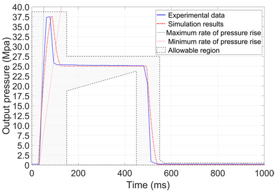
Figure 10.
Experimental results for one period.
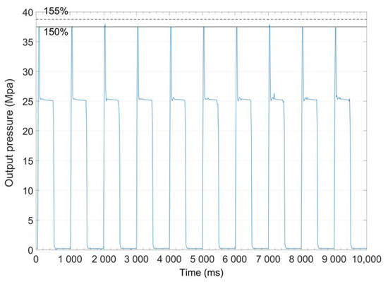
Figure 11.
Repeatability results for 10 periods.
6. Conclusions
In this paper, a new hydraulic high-pressure impulse generator is proposed for providing the standard water hammer wave for long-term usage. The proposed generator has a simple and open-looped structure. The architecture and the working principle are introduced together with the established mathematical models.
In the study, the simulation results based on a commercial software guided the optimization of critical parameters and also provided potential factors that influence the formation of the standard water hammer wave. Subsequently, a test rig was manufactured. The experimental results show the feasibility of the new impulse generator. The specific advantages and limitations of the novel setup are as follows:
- By simply combining a sleeve with three pairs of windows connected to different pressure sources and a rotary spool with two symmetric slots, the standard water hammer wave can be generated easily. The booster piston here can drastically reduce the input pressure. Thus, the system comprises hydraulic components that are easily available and durable for long-duration tests.
- To obtain the standard water hammer wave accurately, a throttle valve inside the rotary valve is used to control the rate of pressure rise. A withdraw chamber on the booster piston is designed to ensure that the wave decays as soon as possible. The pressure gradients and heights of the three windows are carefully designed and optimized to maintain the main body of the wave.
- The primary limitation of the new impulse generator is that the parameters are generally designed for one tested hydraulic component at a time. The simulation results indicate that capacity for modification for different tested hydraulic components is not good. The rotary valve part requires redesigning when the working condition is changed.
In conclusion, this new impulse generator has a simple structure and is built using easily available hydraulic components. Hence, the manufacturing cost is low, and the generator is suitable for repeatability tests or durability tests on hydraulic components.
Author Contributions
Under supervision by B.M., C.D. developed mathematical modeling and wrote the manuscript; Y.H. performed calculations; H.C. performed data analysis; L.Z. performed design; Y.G. performed manufacturing of the prototype. All authors have read and agreed to the published version of the manuscript.
Funding
This work was supported in part by the National Key Research and Development Program of China under Grant 2019YFB2005202, in part by the Natural Science Foundation of China, Grant 51805480 and in part by the Zhejiang Provincial Natural Science Foundation, grant number LY21E050013.
Conflicts of Interest
The authors declare no conflict of interest.
References
- Yang, H.-Y.; Pan, M. Engineering research in fluid power: A review. J. Zhejiang Univ. Sci. A 2015, 16, 427–442. [Google Scholar] [CrossRef]
- Foster, K.; Hannan, D. Fundamental fluidborne and airborne noise generation of axial piston pumps. In Seminar on Quiet Oil Hydraulic Systems, Paper C257/77; Institution of Mechanical Engineers: London, UK, 1977. [Google Scholar]
- Kojima, E.; Yu, J.; Ichiyanagi, T. Experimental determining and theoretical predicting of source flow ripple generated by fluid power piston pumps. SAE Trans. 2000, 109, 348–357. [Google Scholar]
- Zhang, B.; Ma, J.; Hong, H.; Yang, H.; Fang, Y. Analysis of the flow dynamics characteristics of an axial piston pump based on the computational fluid dynamics method. Eng. Appl. Comput. Fluid Mech. 2017, 11, 86–95. [Google Scholar] [CrossRef]
- Manring, N.D. The discharge flow ripple of an axial-piston swash-plate type hydrostatic pump. J. Dyn. Syst. Meas. Control 2000, 122, 263–268. [Google Scholar] [CrossRef]
- Man, Z. Generation and Application of Ultra-High Pressure Hydraulic Impulse Waveform; Zhejiang University: Hangzhou, China, 2015. [Google Scholar]
- SANS Institute. SAE Handbook J343: Test and Test Procedures for SAE 100R Series Hydraulic Hose and Hose Assemblies; Society of Automotive Engineers: Warrendale, PA, USA, 2000. [Google Scholar]
- ISO. Aerospace-Fluid Systems-Impulse Testing of Hydraulic Hose, Tubing and Fitting Assemblies; ISO: Geneva, Switzerland, 2012; Volume 6772. [Google Scholar]
- ISO. Hydraulic Fluid Power—Hoses and Hose Assemblies—Test Methods; ISO: Geneva, Switzerland, 2002; Volume 6605. [Google Scholar]
- SANS Institute. SAE Handbook AIR1228: Standard Impulse Machine Equipment and Operation; Society of Automotive Engineers: Warrendale, PA, USA, 2000. [Google Scholar]
- Song, K.; Zhao, S.; Liao, J.; Dou, Y.; Zhao, X. Research on key technology of hydraulic impulse testing equipment. J. Aerosp. Eng. 2011, 24, 409–414. [Google Scholar] [CrossRef]
- Man, Z.; Ding, F.; Ding, C.; Liu, S. Hydraulic Impulse-Testing System with Pressure Difference Feedback from a Second-Stage Valve. J. Aerosp. Eng. 2015, 28. [Google Scholar] [CrossRef]
- Man, Z.; Ding, F.; Ding, C.; Liu, S. Study of an energy regeneration system with accumulator for hydraulic impulse testing equipment. Stroj. Vestn. J. Mech. Eng. 2015, 61, 196–206. [Google Scholar] [CrossRef]
- Filo, G.; Lisowski, E.; Domagała, M.; Fabiś-Domagała, J.; Momeni, H. Modelling of pressure pulse generator with the use of a flow control valve and a fuzzy logic controller. AIP Conf. Proc. 2018, 2029, 020015. [Google Scholar]
- Chen, L. High-pressure hose impluse test equipment. Hongdu Sci. Technol. 2008, 2, 48–51. (In Chinese) [Google Scholar]
- Samodro, R.A.; Choi, I.-M. Optimization of an impulse pressure generator based on the drop-weight method. Rev. Sci. Instrum. 2019, 90, 095111. [Google Scholar] [CrossRef] [PubMed]
- Yang, J.; Fan, S.; Li, B.; Huang, R.; Shi, Y.; Shi, B. Dynamic modeling of liquid impulse pressure generator for calibration of pressure sensors. Sens. Actuators A Phys. 2018, 279, 120–131. [Google Scholar] [CrossRef]
- Theimer, A.R.; Kolle, J.J. Hydraulic Pulse Valve with Improved Wear Life and Performance. U.S. Patent 10,465,475, 5 November 2019. [Google Scholar]
- Murrenhoff, H. Grundlagen der Fluidtechnik, 4th ed.; Shaker Verlag: Aachen, Germany, 2015. [Google Scholar]
- Ding, C.; Murrenhoff, H. Accuracy estimation of a novel setup for online bulk modulus measurement in hydraulic systems. O+P Ölhydraul. Pneum. 2016, 3, 2–9. [Google Scholar]
- Schrank, K.; Murrenhoff, H.; Stammen, C. Measurements of air absorption and air release characteristics in hydraulic oils at low pressure. In Fluid Power Systems Technology; American Society of Mechanical Engineers: New York, NY, USA, 2013; p. V001T001A030. [Google Scholar]
Publisher’s Note: MDPI stays neutral with regard to jurisdictional claims in published maps and institutional affiliations. |
© 2021 by the authors. Licensee MDPI, Basel, Switzerland. This article is an open access article distributed under the terms and conditions of the Creative Commons Attribution (CC BY) license (http://creativecommons.org/licenses/by/4.0/).