Modeling and Control of an Underactuated System for Dynamic Body Weight Support


Abstract
:Featured Application
Abstract
1. Introduction
2. Methodology and Research Object
3. Dynamic Equations of Motion
4. Control System Modeling
5. Closed System Stability
6. Simulation Research
- Variant 1: A person during rehabilitation performs movements pursuant to (19) without body weight support;
- Variant 2: During rehabilitation, a person performs movements pursuant to (19) with body weight support of 300 N;
- Variant 3: During rehabilitation, a person performs movements with body weight support of 300 N.
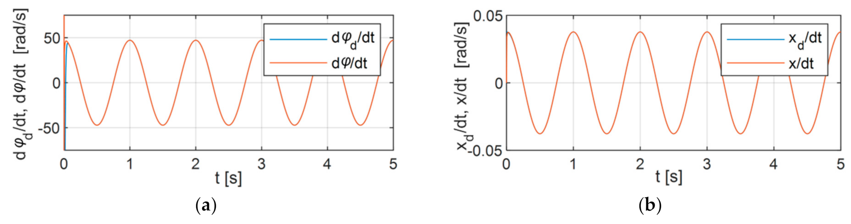
6.1. Variant 1
6.2. Variant 2
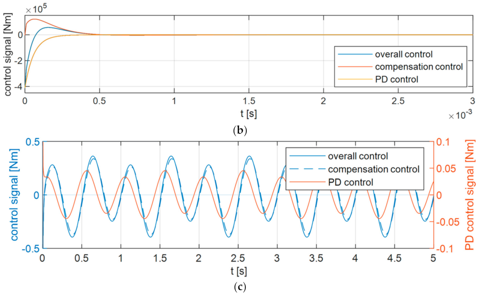
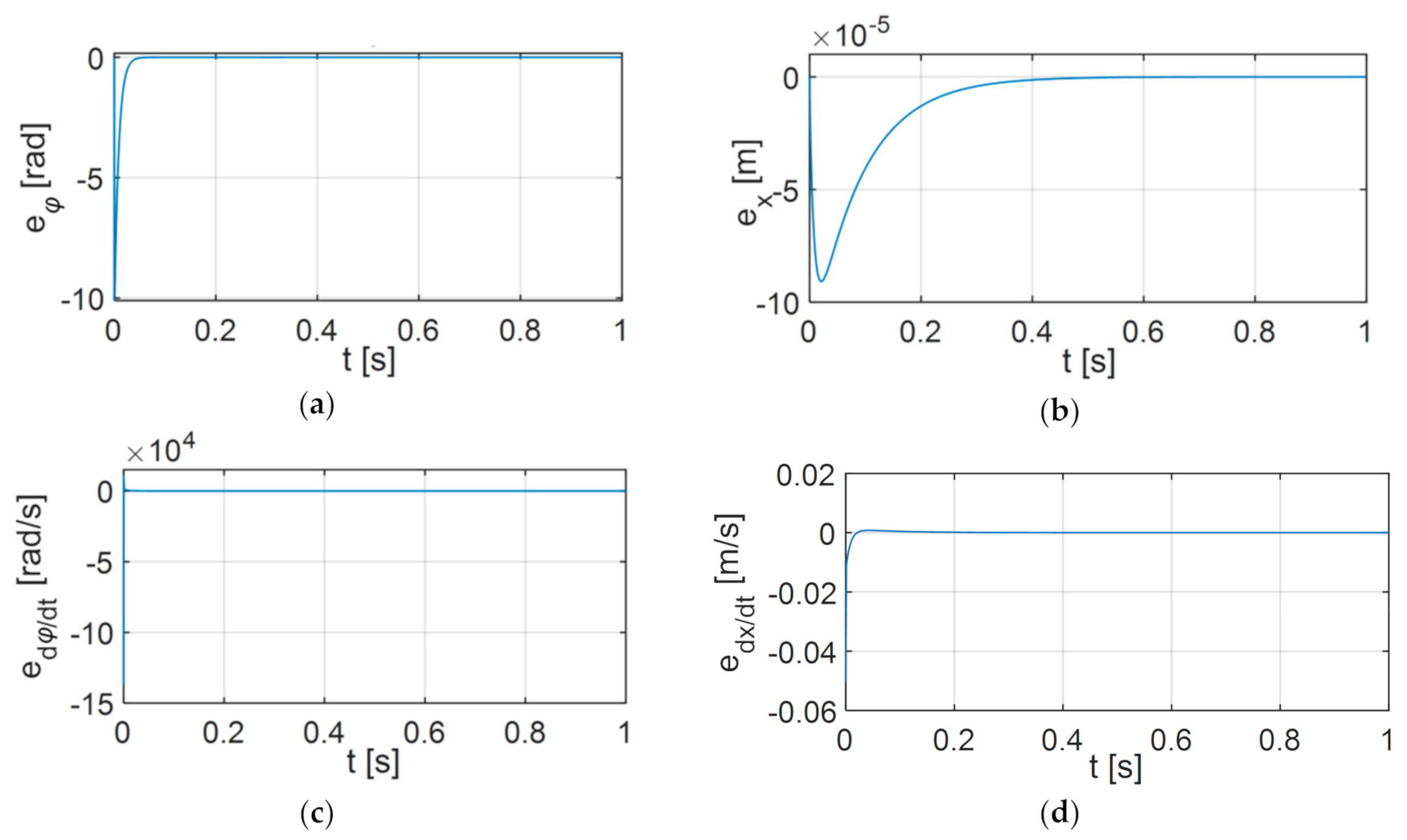
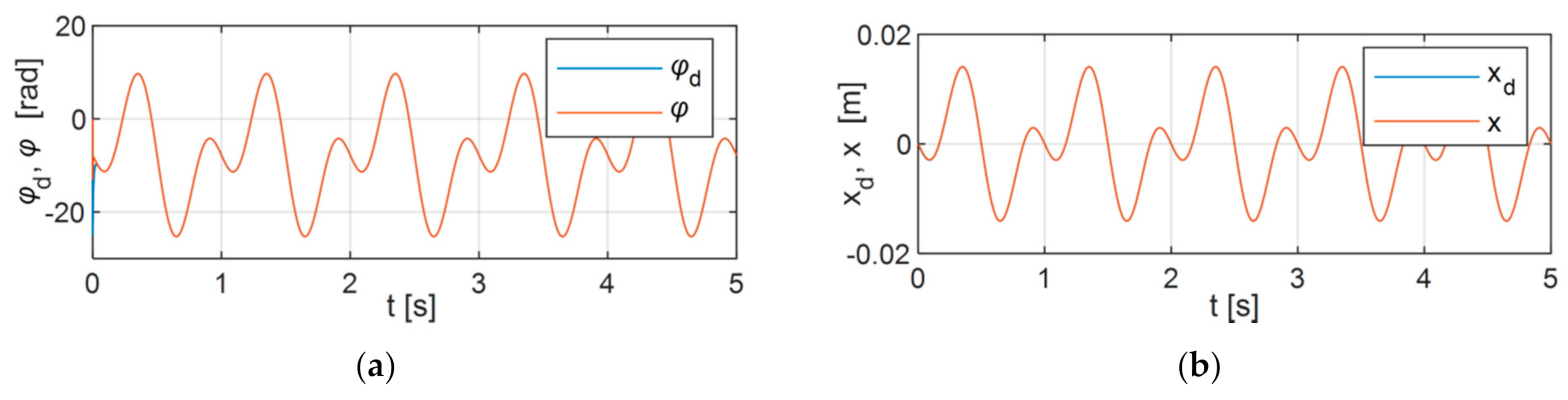
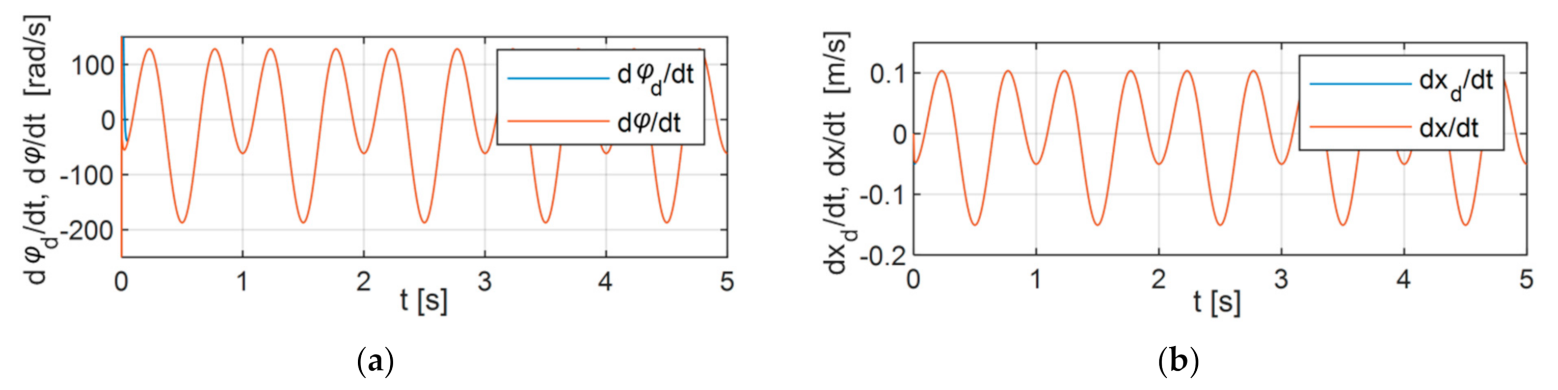
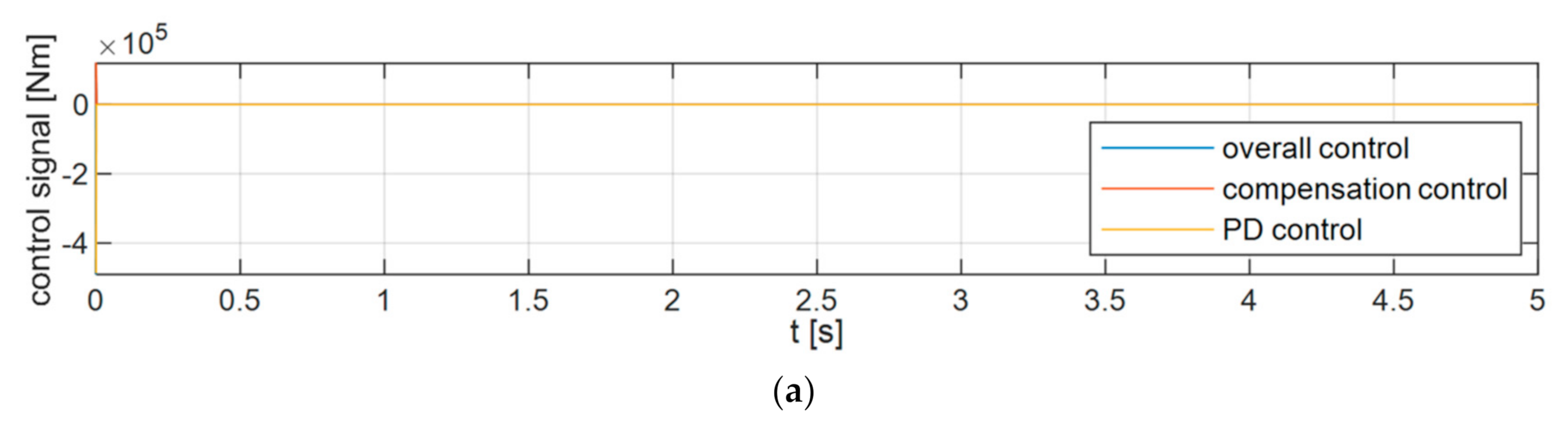
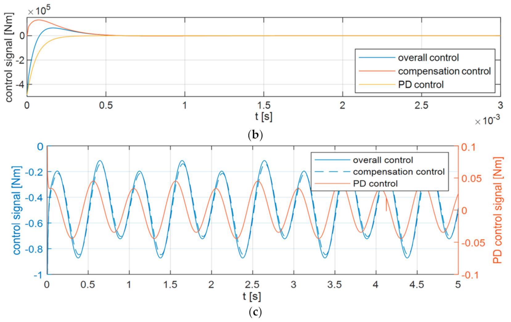
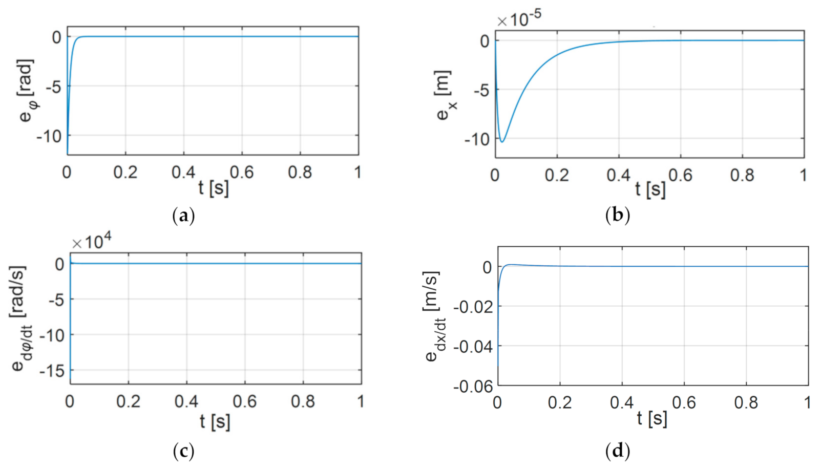
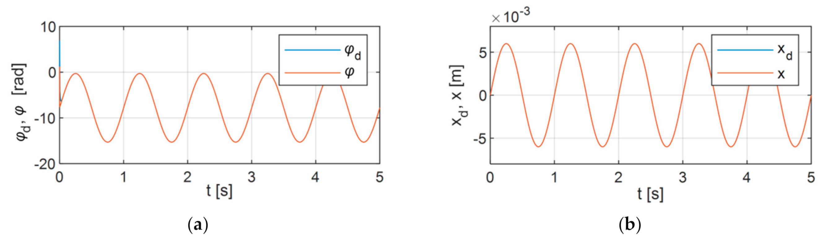
6.3. Variant 3
6.4. Analysis of the Results
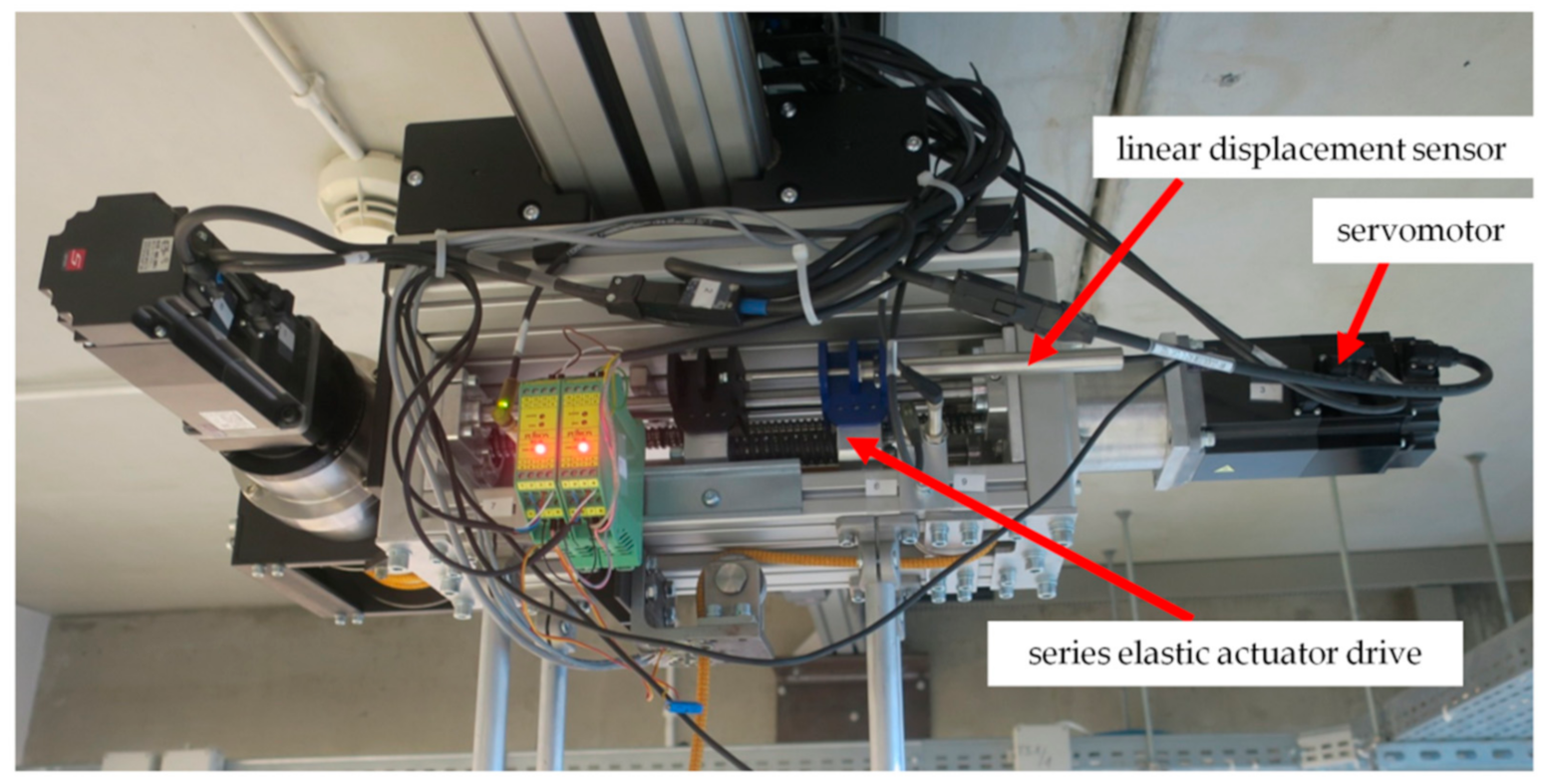
7. Experimental Research
- -
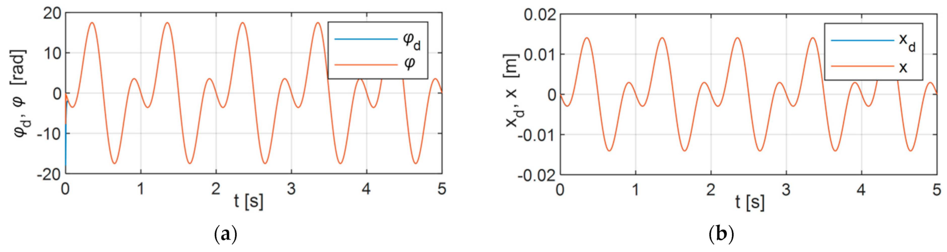
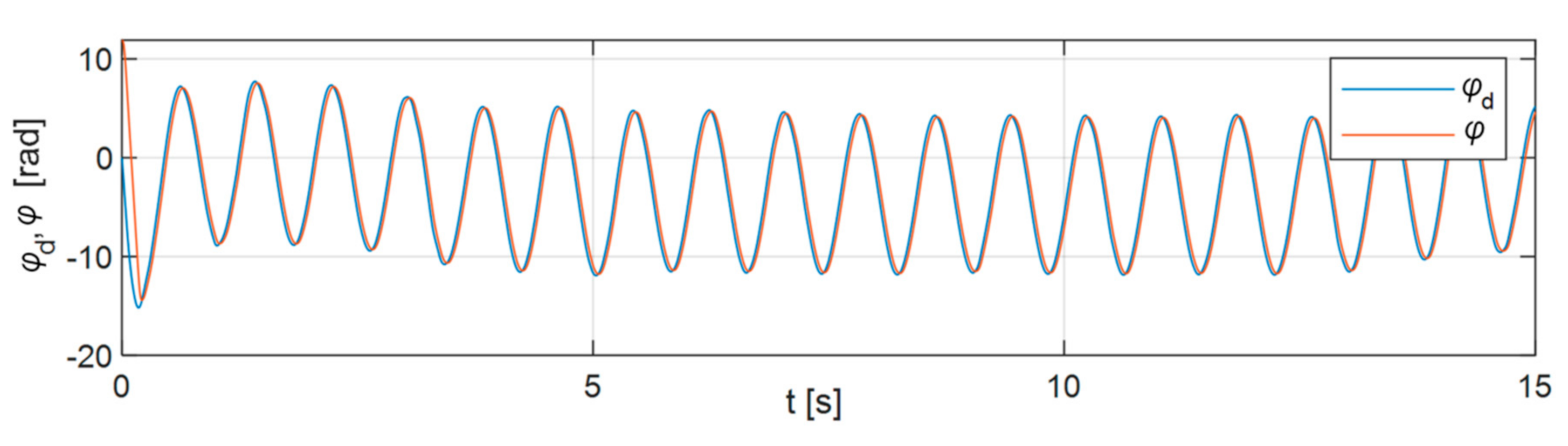
- Set and realized positions of the passive and active parts of the body weight support system;
- -
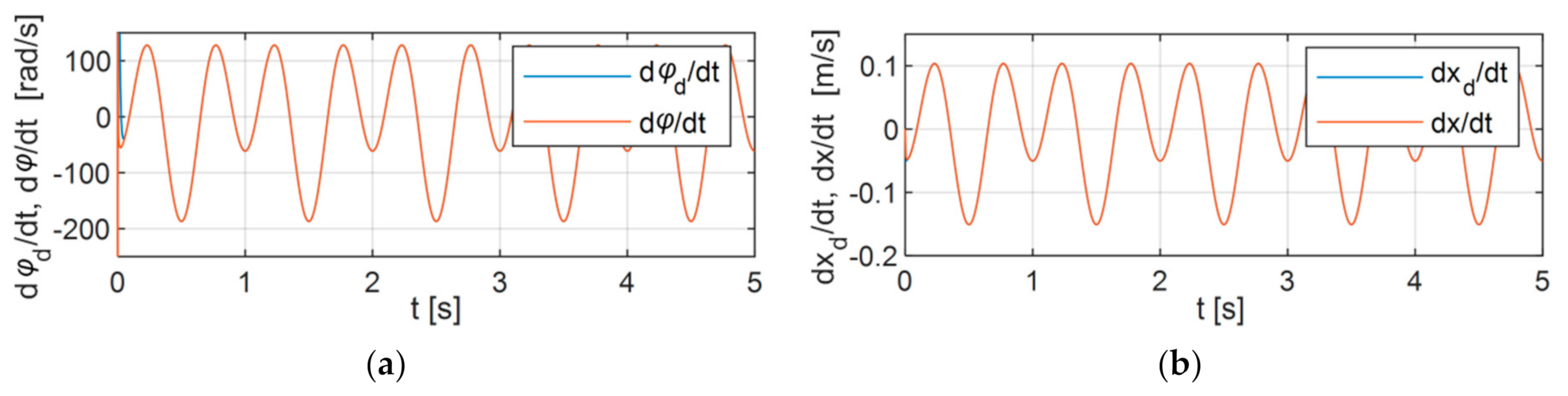
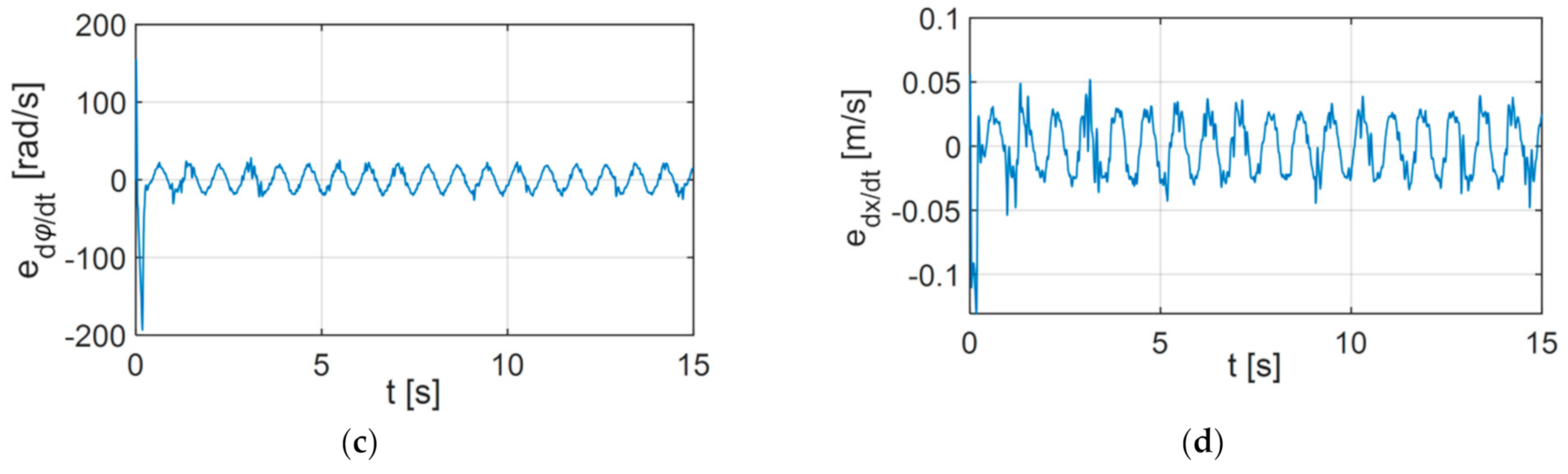
- Set and realized speeds of the passive and active parts of the body weight support system;
- -
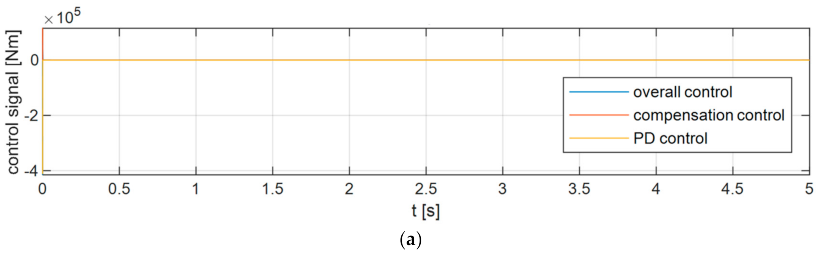
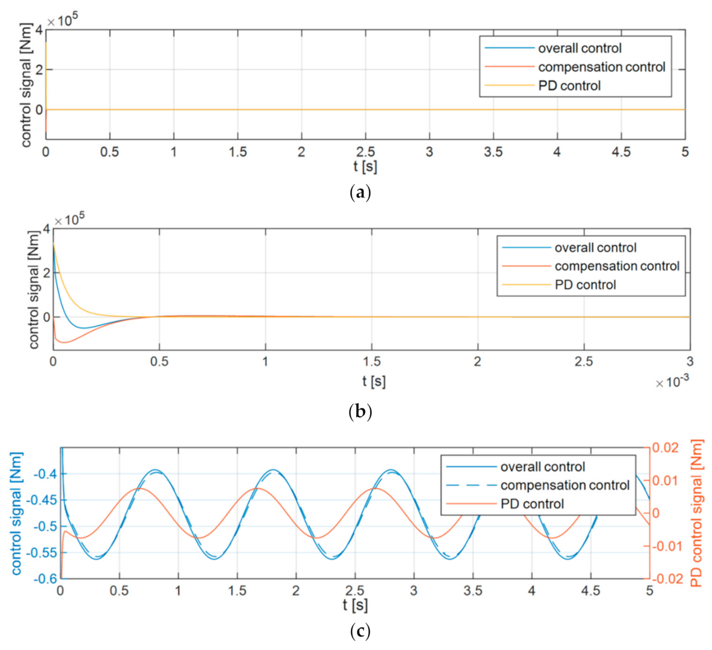
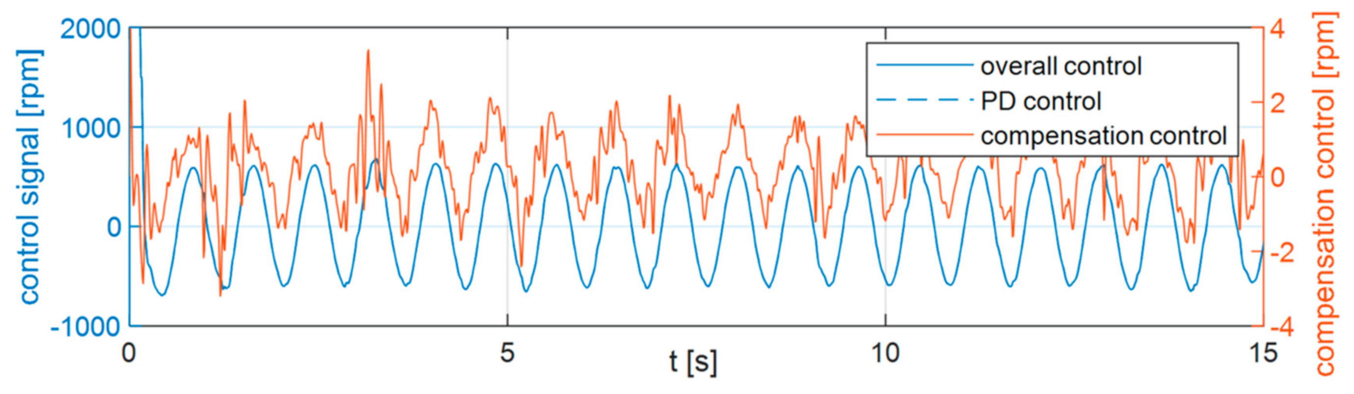
- Values of control signals;
- -
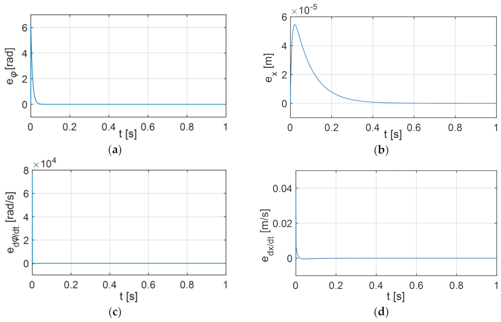
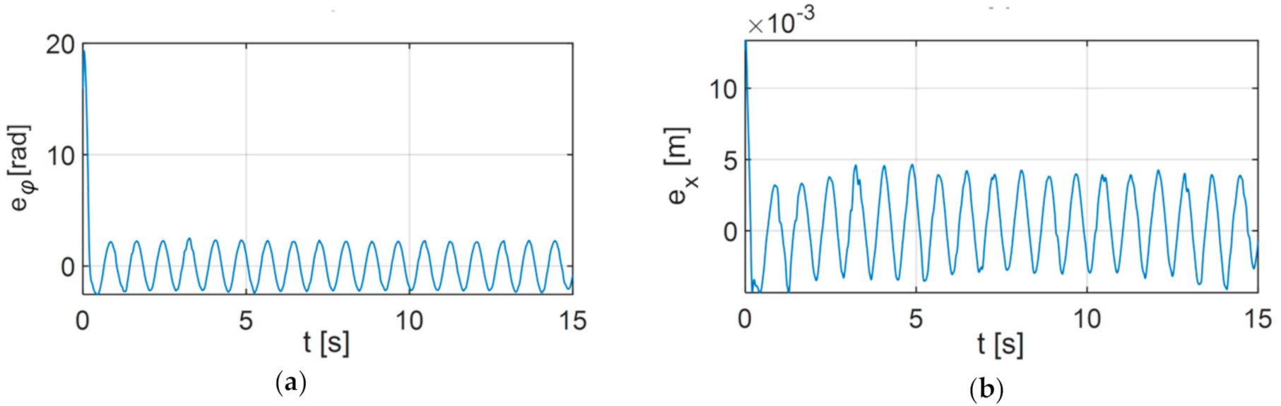
- Follow-up movement errors;
- -
- The value of the body weight support force (from the force sensor).
8. Summary and Conclusions
Author Contributions
Funding
Institutional Review Board Statement
Informed Consent Statement
Data Availability Statement
Conflicts of Interest
References
- Frey, M.; Colombo, G.; Vaglio, M.; Bucher, R.; Jörg, M.; Riener, R. A Novel Mechatronic Body Weight Support System. IEEE Trans. Neural Syst. Rehabil. Eng. 2006, 14, 311–321. [Google Scholar] [CrossRef] [PubMed]
- Apte, S.; Plooij, M.; Vallery, H. Simulation of human gait with body weight support: Benchmarking models and unloading strategies. J. Neuroeng. Rehabil. 2020, 17, 81. [Google Scholar] [CrossRef] [PubMed]
- Huber, J.P.; Sawaki, L. Dynamic body-weight support to boost rehabilitation outcomes in patients with non-traumatic spinal cord injury: An observational study. J. Neuroeng. Rehabil. 2020, 17, 157. [Google Scholar] [CrossRef] [PubMed]
- Zhou, Y.; Chen, S. Fuzzy Control For Treadmill Permanent Magnet Synchronous Motor Speed System. In Proceedings of the 5th International Conference on Advanced Robotics and Mechatronics (ICARM), Shenzhen, China, 18–21 December 2020; pp. 646–651. [Google Scholar] [CrossRef]
- Plooij, M.; Keller, U.; Sterke, B.; Komi, S.; Vallery, H.; Von Zitzewitz, J. Design of RYSEN: An intrinsically safe and low-power three-dimensional Overground body weight support. IEEE Robot. Autom. Lett. 2018, 3, 2253–2260. [Google Scholar] [CrossRef] [Green Version]
- Van Thuc, T.; Yamamoto, S.-I. Development of a Body Weight Support System Using Pneumatic Muscle Actuators: Controlling and Validation. Adv. Mech. Eng. 2016, 8. [Google Scholar] [CrossRef]
- Colombo, G.; Jorg, M.; Dietz, V. Driven gait orthosis to do locomotor training of paraplegic patients. In Proceedings of the 22nd Annual International Conference of the IEEE Engineering in Medicine and Biology Society (Cat. No. 00CH37143), Chicago, IL, USA, 23–28 July 2000; Volume 4, pp. 3159–3163. [Google Scholar] [CrossRef]
- Hesse, S. Locomotor therapy in neurorehabilitation. Neurorehabilitation 2001, 16, 133–139. [Google Scholar] [CrossRef]
- Veneman, J.F.; Kruidhof, R.; Hekman, E.E.; Ekkelenkamp, R.; Van Asseldonk, E.H.; Van Der Kooij, H. Design and evaluation of the LOPES exoskeleton robot for interactive gait rehabilitation. IEEE Trans. Neural Syst. Rehabil. Eng. 2007, 15, 379–386. [Google Scholar] [CrossRef] [Green Version]
- Jin, X.; Cui, X.; Agrawal, S.K. Design of a cable-driven active leg exoskeleton (c-alex) and gait training experiments with human subjects. In Proceedings of the 2015 IEEE International Conference on Robotics and Automation (ICRA), Seattle, WA, USA, 26–30 May 2015; pp. 5578–5583. [Google Scholar] [CrossRef]
- Urendes, E.; Asín-Prieto, G.; Ceres, R.; García-Carmona, R.; Raya, R.L.; Pons, J. HYBRID: Ambulatory Robotic Gait Trainer with Movement Induction and Partial Weight Support. Sensors 2019, 19, 4773. [Google Scholar] [CrossRef] [Green Version]
- Mehrholz, J.; Pohl, M.; Elsner, B. Treadmill training and body weight support for walking after stroke. Stroke 2014, 45, E76–E77. [Google Scholar] [CrossRef]
- Cao, J.; Xie, S.Q.; Das, R.; Zhu, G.L. Control strategies for effective robot assisted gait rehabilitation: The state of art and future prospects. Med. Eng. Phys. 2014, 36, 1555–1566. [Google Scholar] [CrossRef]
- Lünenburger, L.; Colombo, G.; Riener, R. Biofeedback for robotic gait rehabilitation. J. Neuroeng. Rehabil. 2007, 4, 1. [Google Scholar] [CrossRef] [PubMed] [Green Version]
- Lopez-Samaniego, L.; Garcia-Zapirain, B. A Robot-Based Tool for Physical and Cognitive Rehabilitation of Elderly People Using Biofeedback. Int. J. Environ. Res. Public Health 2016, 13, 1176. [Google Scholar] [CrossRef] [PubMed] [Green Version]
- Koenig, A.; Omlin, X.; Bergmann, J.; Zimmerli, L.; Bolliger, M.; Müller, F.; Riener, R. Controlling patient participation during robot-assisted gait training. J. Neuroeng. Rehabil. 2011, 8, 14. [Google Scholar] [CrossRef] [PubMed] [Green Version]
- Solanki, D.; Kumar, S.; Raj, P.; Lahiri, U. Body Weight Support Assisted Virtual Reality based Treadmill Walk with Gait Characterization. In Proceedings of the 10th International Conference on Computing, Communication and Networking Technologies (ICCCNT), Kanpur, India, 6–8 July 2019; pp. 1–7. [Google Scholar] [CrossRef]
- Jochymczyk-Woźniak, K.; Nowakowska, K.; Polechoński, J.; Sładczyk, S.; Michnik, R. Physiological Gait versus Gait in VR on Multidirectional Treadmill—Comparative Analysis. Medicina 2019, 55, 517. [Google Scholar] [CrossRef] [PubMed] [Green Version]
- Gembalczyk, G.; Duda, S.; Kciuk, S.; Gasiorek, D.; Mezyk, A. Mechatronic treadmill for gait reeducation with control algorithm of treadmill speed adaptation. Proc. Inst. Mech. Eng. Part C J. Mech. Eng. Sci. 2018, 233, 2239–2247. [Google Scholar] [CrossRef]
- Wyss, D.; Bartenbach, V.; Pennycott, A.; Riener, R.; Vallery, H. A body weight support system extension to control lateral forces: Realization and validation. In Proceedings of the IEEE International Conference on Robotics and Automation (ICRA), Hong Kong, China, 31 May–7 June 2014; pp. 328–332. [Google Scholar] [CrossRef]
- Hidler, J.; Brennan, D.; Black, I.; Nichols, D.; Brady, K.; ZeroG, T.N. Overground gait and balance training system. J. Rehabil. Res. Dev. 2011, 48, 287–298. [Google Scholar] [CrossRef]
- Lu, Q.; Liang, J.; Qiao, B.; Ma, O. A New Active Body Weight Support System Capable of Virtually Offloading Partial Body Mass. IEEE ASME Trans. Mechatron. 2013, 18, 11–20. [Google Scholar] [CrossRef]
- Herbin, P.; Pajor, M. The torque control system of exoskeleton ExoArm 7-DOF used in bilateral teleoperation system. In AIP Conference Proceedings; AIP Publishing LLC: Melville, NY, USA, 2018; Volume 2029, p. 020020. [Google Scholar] [CrossRef]
- Mirzaee, A.; Moghadam, M.M.; Saba, A.M. Conceptual Design of an Active Body Weight Support System Using a Linear Series Elastic Actuator. In Proceedings of the 2019 7th International Conference on Robotics and Mechatronics (ICRoM), Tehran, Iran, 20–21 November 2019; pp. 80–87. [Google Scholar] [CrossRef]
- Munawar, H.; Patoglu, V. Gravity-assist: A series elastic body weight support system with inertia compensation. In Proceedings of the 2016 IEEE/RSJ International Conference on Intelligent Robots and Systems (IROS), Daejeon, South Korea, 9–14 October 2016; pp. 3036–3041. [Google Scholar] [CrossRef]
- Blajer, W.; Kołodziejczyk, K. Control of underactuated mechanical systems with servo-constraints. Nonlinear Dyn. 2007, 50, 781–791. [Google Scholar] [CrossRef]
- Spong, M.W. Underactuated mechanical systems. In Control Problems in Robotics and Automation. Lecture Notes in Control and Information Sciences; Siciliano, B., Valavanis, K.P., Eds.; Springer: Berlin, Germany, 1998; Volume 230, pp. 135–150. [Google Scholar] [CrossRef]
- Birouaș, F.I.; Țarcă, R.C.; Dzitac, S.; Dzitac, I. Preliminary Results in Testing of a Novel Asymmetric Underactuated Robotic Hand Exoskeleton for Motor Impairment Rehabilitation. Symmetry 2020, 12, 1470. [Google Scholar] [CrossRef]
- Hoang, U.T.T.; Le, H.X.; Thai, N.H.; Pham, H.V.; Nguyen, L. Consistency of Control Performance in 3D Overhead Cranes under Payload Mass Uncertainty. Electronics 2020, 9, 657. [Google Scholar] [CrossRef] [Green Version]
- Łyp, M.; Stanisławska, I.; Witek, B.; Olszewska-Żaczek, E.; Czarny-Działak, M.; Kaczor, R. Robot-Assisted Body-Weight-Supported Treadmill Training in Gait Impairment in Multiple Sclerosis Patients: A Pilot Study. In Progress in Medical Research; Springer: Cham, Switzerland, 2018; pp. 111–115. [Google Scholar] [CrossRef]
- Gama, G.L.; Celestino, M.L.; Barela, J.A.; Forrester, L.; Whitall, J.; Barela, A.M. Effects of gait training with body weight support on a treadmill versus overground in individuals with stroke. Arch. Phys. Med. Rehabil. J. 2017, 98, 738–745. [Google Scholar] [CrossRef] [PubMed] [Green Version]
- Barela, A.M.F.; Gama, G.L.; Russo-Junior, D.V.; Celestino, M.L.; Barela, J.A. Gait alterations during walking with partial body weight supported on a treadmill and over the ground. Sci. Rep. 2019, 9, 8139. [Google Scholar] [CrossRef] [PubMed]
- Ada, L.; Dean, C.M.; Vargas, J.; Ennis, S. Mechanically assisted walking with body weight support results in more independent walking than assisted overground walking in non-ambulatory patients early after stroke: A systematic review. J. Physiother. 2010, 56, 153–161. [Google Scholar] [CrossRef] [Green Version]
- Gembalczyk, G.; Duda, S.; Świtoński, E. Computational optimization and implementation of control system for mechatronic treadmill with body weight support system. J. Theor. Appl. Mech. 2018, 56, 1179–1191. [Google Scholar] [CrossRef]
- Duda, S.; Gembalczyk, G.; Jurkojc, J.; Kciuk, S.; Michnik, R. Mechatronic solution of components cooperation in the device for gait reeducation. In Proceedings of the ECCOMAS Thematic Conference on Multibody Dynamics 2015, Multibody Dynamics 2015, Barcelona, Spain, 29 June–2 July 2015; pp. 799–805. [Google Scholar]
- Hennessey, C.; Pearson, N.; Plaut, R. Experimental snap loading of synthetic ropes. Shock Vib. 2005, 12, 163–175. [Google Scholar] [CrossRef] [Green Version]
- Zhang, P.; Duan, M.; Ma, J.; Zhang, Y.A. Precise mathematical model for geometric modeling of wire rope strands structure. Appl. Math. Model. 2019, 76, 151–171. [Google Scholar] [CrossRef]
- Sławski, S.; Szymiczek, M.; Kaczmarczyk, J.; Domin, J.; Duda, S. Experimental and Numerical Investigation of Striker Shape Influence on the Destruction Image in Multilayered Composite after Low Velocity Impact. Appl. Sci. 2020, 10, 288. [Google Scholar] [CrossRef] [Green Version]
- Wu, W.; Cao, X. Mechanics model and its equation of wire rope based on elastic thin rod theory. Int. J. Solids Struct. 2016, 102–103, 21–29. [Google Scholar] [CrossRef]
- Weller, S.D.; Banfield, S.J.; Canedo, J. Parameter Estimation for Synthetic Rope Models. In Proceedings of the ASME 2018 37th International Conference on Ocean, Offshore and Arctic Engineering, Volume 1: Offshore Technology, Madrid, Spain, 17–22 June 2018; p. V001T01A072. [Google Scholar] [CrossRef]
- Burghardt, A.; Giergiel, J. Modelling and control of a underactuated sphere and beam system. Commun. Nonlinear Sci. Numer. Simul. 2011, 16, 2350–2354. [Google Scholar] [CrossRef]
- Burghardt, A.; Hendzel, Z. Adaptive neural network control of underactuated system. In Proceedings of the 4th International Conference on Neural Computation Theory and Applications, Barcelona, Spain, 5–7 October 2012; pp. 505–509. [Google Scholar]
- Tran, V.-T.; Sasaki, K.; Yamamoto, S.-I. Influence of Body Weight Support Systems on the Abnormal Gait Kinematic. Appl. Sci. 2020, 10, 4685. [Google Scholar] [CrossRef]
- Gutierrez-Farewik, E.M.; Bartonek, Å.; Saraste, H. Comparison and evaluation of two common methods to measure center of mass displacement in three dimensions during gait. Hum. Mov. Sci. 2006, 25, 238–256. [Google Scholar] [CrossRef]
- Apte, S.; Plooij, M.; Vallery, H. Influence of body weight unloading on human gait characteristics: A systematic review. J. Neuroeng. Rehabil. 2018, 15, 53. [Google Scholar] [CrossRef] [PubMed] [Green Version]
- Dragunas, A.C.; Gordon, K.E. Body weight support impacts lateral stability during treadmill walking. J. Biomech. 2016, 49, 2662–2668. [Google Scholar] [CrossRef] [PubMed] [Green Version]
- Sousa, C.O.; Barela, J.A.; Prado-Medeiros, C.L.; Salvini, T.F.; Barela, A.M. The use of body weight support on ground level: An alternative strategy for gait training of individuals with stroke. J. Neuroeng. Rehabil. 2009, 6, 43. [Google Scholar] [CrossRef] [PubMed] [Green Version]
- Barbeau, H.; Visintin, M. Optimal outcomes obtained with body-weight support combined with treadmill training in stroke subjects. Arch. Phys. Med. Rehabil. 2003, 84, 1458–1465. [Google Scholar] [CrossRef]
- Saków, M.; Marchelek, K. Design and optimisation of regression-type small phase shift FIR filters and FIR-based differentiators with optimal local response in LS-sense. Mech. Syst. Signal. Process. 2020, 107408. [Google Scholar] [CrossRef]
- Yang, X.; Yang, C.; Peng, T.; Chen, Z.; Liu, B.; Gui, W. Hardware-in-the-Loop Fault Injection for Traction Control System. IEEE J. Emerg. Sel. Top. Power Electron. 2018, 6, 696–706. [Google Scholar] [CrossRef]
- Thompson, D.; Yeary, M.; Fulton, C. RF array system equalization and true time delay with FPGA hardware-in-the-loop. In Proceedings of the 2016 IEEE International Symposium on Phased Array Systems and Technology (PAST), Waltham, MA, USA, 18–21 October 2016; pp. 1–5. [Google Scholar] [CrossRef]
- Danek, W.; Pawlak, M. Charpy Impact Testing Machine in Modeling of Vehicle Frontal Crash with Street Lights. Dyn. Syst. Theory Appl. 2018, 249, 73–84. [Google Scholar] [CrossRef]
- Haniszewski, T. Preliminary modeling studies of sudden release of a part of the hoist load with using experimental miniature test crane. Vib. Proced. 2017, 13, 193–198. [Google Scholar] [CrossRef] [Green Version]
- Hanwate, S.D.; Hote, Y.V. Design of PID controller for inverted pendulum using stability boundary locus. In Proceedings of the 2014 Annual IEEE India Conference (INDICON), Pune, India, 11–13 December 2014. [Google Scholar] [CrossRef]
- Puriel-Gil, G.; Yu, W.; Sossa, H. Reinforcement Learning Compensation based PD Control for Inverted Pendulum. In Proceedings of the 2018 15th International Conference on Electrical Engineering, Computing Science and Automatic Control, CCE 2018, Mexico City, Mexico, 5–7 September 2018. [Google Scholar] [CrossRef]
- Wen, Y.; Ortiz, F. Stability analysis of PD regulation for ball and beam system. In Proceedings of the 2005 IEEE Conference on Control Applications, CCA 2005, Toronto, ON, Canada, 28–31 August 2005; pp. 517–522. [Google Scholar] [CrossRef]
- Soriano, L.A.; Zamora, E.; Vazquez-Nicolas, J.M.; Hernández, G.; Barraza Madrigal, J.A.; Balderas, D. PD Control Compensation Based on a Cascade Neural Network Applied to a Robot Manipulator. Front. Neurorobot. 2020, 14. [Google Scholar] [CrossRef]
- Yu, W. PID Control with Intelligent Compensation for Exoskeleton Robots; Academic Press: Cambridge, MA, USA, 2018; ISBN 978-0-12-813380-4. [Google Scholar] [CrossRef]
- Sun, L.; Yin, W.; Wang, M.; Liu, J. Position Control for Flexible Joint Robot Based on Online Gravity Compensation with Vibration Suppression. IEEE Trans. Ind. Electron. 2018, 65, 4840–4848. [Google Scholar] [CrossRef]
- Fang, Y.; Dixon, W.E.; Dawson, D.M.; Zergeroglu, E. Nonlinear coupling control laws for an underactuated overhead crane system. IEEE/ASME Trans. Mechatron. 2003, 8, 418–423. [Google Scholar] [CrossRef] [Green Version]
- Anderson, R.J. Passive computed torque algorithms for robots. In Proceedings of the IEEE Conference on Decision and Control, Tampa, FL, USA, 13–15 December 1989; Volume 2, pp. 1638–1644. [Google Scholar] [CrossRef]
- Moreno-Valenzuela, J.; Aguilar-Avelar, C. Motion Control of Underactuated Mechanical Systems; Springer International Publishing: New York, NY, USA, 2018. [Google Scholar] [CrossRef]
- Diveev, A.; Shmalko, E.; Serebrenny, V.; Zentay, P. Fundamentals of Synthesized Optimal Control. Mathematics 2021, 9, 21. [Google Scholar] [CrossRef]
- Jezernik, S.; Jezernik, K.; Morari, M. Impedance Control Based Gait-Pattern Adaptation for a Robotic Rehabilitation Device. IFAC Proc. Vol. 2002, 35, 389–393. [Google Scholar] [CrossRef]
- Brahmi, B.; Saad, M.; Rahman, M.H.; Brahmi, A. Adaptive Force and Position Control Based on Quasi-Time Delay Estimation of Exoskeleton Robot for Rehabilitation. IEEE Trans. Control Syst. Technol. 2020, 28, 2152–2163. [Google Scholar] [CrossRef]
- Gierlak, P. Position/Force Control of Manipulator in Contact with Flexible Environment. Acta Mech. Autom. 2019, 13, 16–22. [Google Scholar] [CrossRef] [Green Version]
- Shan, C.H.; Chen, Z.; Yao, B.; Xiaocong, Z.; Shiqiang, Z.; Qingfeng, W.; Yang, S. Cascade force control of lower limb hydraulic exoskeleton for human performance augmentation. In Proceedings of the IECON 2016—42nd Annual Conference of the IEEE Industrial Electronics Society, Florence, Italy, 23–26 October 2016; pp. 512–517. [Google Scholar] [CrossRef]


| Parameter | Unit | Value |
|---|---|---|
| kg m2 | 0.00018 | |
| kg | 10.5 + 2F/g | |
| kg m2/s | 0.0005 | |
| kg/s | 300 | |
| N/m | 96,800 | |
| h | mm | 0.005 |
| Parameter | Unit | Value |
|---|---|---|
| 1/s | 120 | |
| 1/s | 6200 | |
| kg m2/s | 3 | |
| kg/s | 120 |
Publisher’s Note: MDPI stays neutral with regard to jurisdictional claims in published maps and institutional affiliations. |
© 2021 by the authors. Licensee MDPI, Basel, Switzerland. This article is an open access article distributed under the terms and conditions of the Creative Commons Attribution (CC BY) license (http://creativecommons.org/licenses/by/4.0/).
Share and Cite
Gembalczyk, G.; Gierlak, P.; Duda, S. Modeling and Control of an Underactuated System for Dynamic Body Weight Support. Appl. Sci. 2021, 11, 905. https://doi.org/10.3390/app11030905
Gembalczyk G, Gierlak P, Duda S. Modeling and Control of an Underactuated System for Dynamic Body Weight Support. Applied Sciences. 2021; 11(3):905. https://doi.org/10.3390/app11030905
Chicago/Turabian StyleGembalczyk, Grzegorz, Piotr Gierlak, and Slawomir Duda. 2021. "Modeling and Control of an Underactuated System for Dynamic Body Weight Support" Applied Sciences 11, no. 3: 905. https://doi.org/10.3390/app11030905