Abstract
Background: A maxillofacial prosthesis, an alternative to surgery for the rehabilitation of patients with facial disabilities (congenital or acquired due to malignant disease or trauma), are meant to replace parts of the face or missing areas of bone and soft tissue and restore oral functions such as swallowing, speech and chewing, with the main goal being to improve the quality of life of the patients. The conventional procedures for maxillofacial prosthesis manufacturing involve several complex steps, are very traumatic for the patient and rely on the skills of the maxillofacial team. Computer-aided design and computer-aided manufacturing have opened a new approach to the fabrication of maxillofacial prostheses. Our review aimed to perform an update on the digital design of a maxillofacial prosthesis, emphasizing the available methods of data acquisition for the extraoral, intraoral and complex defects in the maxillofacial region and assessing the software used for data processing and part design. Methods: A search in the PubMed and Scopus databases was done using the predefined MeSH terms. Results: Partially and complete digital workflows were successfully applied for extraoral and intraoral prosthesis manufacturing. Conclusions: To date, the software and interface used to process and design maxillofacial prostheses are expensive, not typical for this purpose and accessible only to very skilled dental professionals or to computer-aided design (CAD) engineers. As the demand for a digital approach to maxillofacial rehabilitation increases, more support from the software designer or manufacturer will be necessary to create user-friendly and accessible modules similar to those used in dental laboratories.
1. Introduction
Maxillofacial prosthesis production for the rehabilitation of patients with facial disabilities (congenital or acquired due to malignant disease or trauma) is often challenging and complex, depending on the type of defect. These prostheses are meant to replace parts of the face, such as the nose, ear, eye and surrounding tissues or missing areas of bone and soft tissue, restoring oral functions such as swallowing, speech and chewing, with the main goal being to improve the quality of life of the patient [1].
Conventional procedures for maxillofacial prosthesis manufacturing involve several complex steps which are costly, time-consuming, very traumatic for the patient and rely on the skills of the maxillofacial team, dental clinician and maxillofacial technician [2].
The complexity of conventional maxillofacial prosthodontics production requires several weeks and a great number of visits by the patient for try-ins, functional and esthetic adjustments [3]. For most patients, surgical correction is not an option, and the extent of their defects induce a lack of self-confidence, impairing their daily activities and social lives [4].
Despite their great role in the social integration of the patients and preserving anatomical structures after surgical treatments, maxillofacial prostheses, being classified as cosmetic devices, are not covered by health insurance in many countries. The conventional fabrication protocol has a great number of limitations, primarily related to the high technical expertise required, time, effort, and cost, plus retention and esthetic problems, making it less accessible to the global patient community. Only a small number of these patients can afford the high cost of the prosthesis, and even fewer of them can get access to such sophisticated devices in a timely manner.
Advancements in the fields of computer-aided design (CAD) and computer-aided manufacturing (CAM) and the implementation of these technologies in medicine offered new methods for design and construction, and new options for materials and technologies were rapidly introduced in all dental fields [5]. However, many aspects of these technological advancements have still not been entirely functional for maxillofacial prosthetic rehabilitation [6,7] despite the acute necessity for reducing production costs, shortening the time, improving comfort and increasing patients’ accessibility.
The present scoping review aimed to perform an update on the digital design of maxillofacial prostheses, emphasizing the available methods of data acquisition for the extraoral, intraoral and complex defects in the maxillofacial region and assess the software used for data processing and part design.
2. Materials and Methods
The general question asked in the present review was the following: Is the full digital workflow an option for maxillofacial prosthesis manufacturing? This was followed by a secondary question: Is the used software accessible to all dental technicians involved in maxillofacial prosthodontics?
For the search protocol, a search in the PubMed and Scopus databases was performed using the following MeSH terms: maxillofacial prosthesis; digital technology; imaging, three-dimensional; computer-aided design (CAD); computer-assisted manufacturing (CAM); and printing, three-dimensional. A manual search in relevant prosthetic journals, such as the Journal of Prosthetic Dentistry, Journal of Prosthodontics, Journal of Prosthodontic Research, Journal of Prosthodontics-Implant Esthetic and Reconstructive Dentistry, Journal of Advanced Prosthodontics, International Journal of Prosthodontics, as well as in the reference lists of the included papers, was also done.
Randomized clinical trials, case reports, case series, technical notes, letters to the editor and reviews including humans in the English language with detailed descriptions of the data acquisition and the software used for data processing and maxillofacial prosthesis part design were included in this review.
The inclusion criteria were as follows: a digital workflow for facial, nasal, ocular and auricular prostheses; maxillary obturator and mandibular defect replacement prostheses, including dental structure replacement; and complex facial and maxillary prostheses.
The conventional manufacturing workflow, surgical templates for tumor excision planning and guides for implant insertion were excluded.
2.1. Classification of the Maxillofacial Defects
For clarity and a more comprehensive description of maxillofacial prosthesis reconstruction, the defects were classified as extraoral (missing nose, eye, orbit, ear or face parts), intraoral (missing parts of the maxilla, middle face and mandible) and complex (missing extraoral and intraoral anatomical parts), as shown in Figure 1. For the intraoral maxillary and midface defects, Brown and Shaw classification, based on the vertical extent defect measure (classes I–VI) and the horizontal extent defect measure (a–d), was used [8]. For mandibular defects, Cantor and Curtis classification, proven to be useful for guiding surgical and prosthetic rehabilitation [9,10,11], was considered.
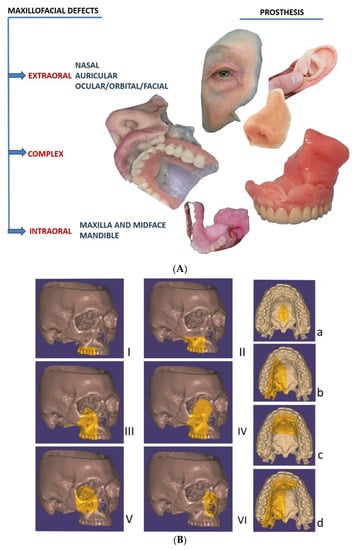
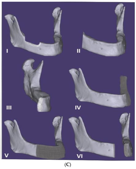
Figure 1.
(A) Classification of the maxillofacial defects in extraoral, complex and intraoral cases (including extraoral complex and intraoral prostheses). (B) The intraoral maxilla and midface defects, classified according to Brown and Shaw classification in six classes [8]: vertical classification, with a maxillectomy not causing an oronasal fistula (I); not involving the orbit (II); involving the orbital adnexae with orbital retention (III); with orbital enucleation or exenteration (IV); with an orbitomaxillary defect (V); and with a nasomaxillary defect (VI), and for horizontal classification, only a palatal defect not involving the dental alveolus (a); less than or equal to a half unilateral (b); less than or equal to a half bilateral or transverse anterior (c); a greater than half maxillectomy (d). (C) The intraoral mandibular defects, classified according to Cantor and Curtis classification in six classes [10,11]: radical alveolectomy with preservation of mandibular continuity (I); lateral resection of the mandible distal to the cusp area (II); lateral resection of the mandible to the midline (III); lateral bone graft and surgical reconstruction (IV); anterior bone graft and surgical reconstruction (V); and anterior mandibular resection without surgical reconstruction (VI).
2.2. Digital Versus Conventional Workflow for Maxillofacial Prosthesis Design and Manufacturing
2.2.1. Conventional Workflow
A conventional workflow for maxillofacial prosthesis production includes the following steps (Figure 2). An accurate impression of the area requiring prosthesis is achieved by selecting a suitable impression material (hydrocolloid alginates or elastic silicone polymers are the most-used materials) according to the type of defect, size and presence or absence of any undercuts in the respective area, with a custom tray often being required. Some anatomic undercuts are blocked so as to remove the impression without damaging the surrounding tissue. After pouring the impression, the gypsum cast is obtained, and a wax model of the anatomic part to be replaced is fabricated. For reproducing the natural morphological details of the defect, the wax is carved, followed by a try-in of the maxillofacial prosthesis wax-up with the corresponding adjustments for marginal fit and esthetic appearance. The molds are produced using the final retouched wax-up by applying the lost wax method, where gypsum is poured over the wax model and the wax is then simply removed with hot water [12]. The final prosthesis is obtained using the adequate material. For intraoral and complex defects including a part or the complete dental arch, an impression of the opposite arch and the mounting in a semi-adjustable articulator is also necessary before the try-in. Complex defects, including intraoral and extraoral missing anatomical parts, require the use of materials with different characteristics, such as acrylic resins or silicones.
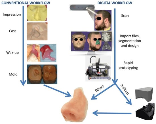
Figure 2.
Comparison of conventional and digital workflows for nasal extraoral prosthesis manufacturing. For the conventional technique (left), an impression is taken of the defect and surrounding tissue, followed by a casting and wax-up of the prosthesis with a holding support for facilitating the try-in, creating the mold. For the digital technique (right), 3D scanning is performed with a Bellus Arc 1 facial scanner, followed by importing the files into a computer-aided design (CAD) program, designing the prosthesis and printing the mold (indirect path) or the final nasal prosthesis directly using a 3D printer.
2.2.2. Digital Workflow
The digital manufacturing of maxillofacial prostheses requires the same general steps. Defect data acquisition can be obtained via medical scans and surface scans [12]. Medical scanning includes computed tomography (CT) with the version that requires a lower radiation dose and is specific to the maxillofacial region; cone beam computed tomography (CBCT) or magnetic resonance imaging (MRI) [13], generating files in the Digital Imaging and Communication in Medicine (DICOM) format; and convertible 3D models of a patient’s specific anatomy. Surface scanners (e.g., laser scanners, structured light scanners, facial scanners and intraoral scanners) are a good option for defect data acquisition [14]. Photogrammetry—the extraction of three-dimensional measurements from two-dimensional images of the anatomical parts using specific software—is also used in producing 3D surface models of patients’ faces [15].
The design of the external or internal maxillofacial prosthesis is obtained using a wide variety of existing CAD programs and software suites, either open-source (OS) or commercially available (CA) (Table 1). Rapid prototyping, particularly additive manufacturing, is used to obtain the final prosthesis. Maxillofacial prostheses, be they external, internal or complex according to the proposed digital workflow and the material utilized, are manufactured indirectly by obtaining a model of the prosthesis or the mold, followed by the conventional workflow for anatomic part processing, or directly by 3D printing with adequate material (e.g., silicone-based elastomers and acrylic resins, among others) (Figure 2).

Table 1.
Data acquisition, editing, design and manufacturing of maxillofacial prostheses.
3. Results
The digital workflow for extraoral prosthesis anaplastology (nose, ear or orbital, ocular or facial replacement) was described in 46 scientific papers, including case reports, case series, technical reports, proofs of concept and, for intraoral prosthesis, in 13 papers. However, the digital workflow was only used for removable prostheses for maxillary and midface defects (obturators). The mandibular defects were restored preferably through patient-specific implants [73,74] or surgical reconstruction techniques. No digital workflow description on Cantor and Curtis class I, II, III and IV prosthetic restorations has been found so far.
3.1. Anatomic Data Acquisition
The data available from the existing literature revealed the following acquisition modalities: CT scans [26,29,31,36,39,41,43,46,54,60,67,71], MRIs, CBCTs (for maxillary obturators) [22,24], structured light scanners [19,20,21,23,58], laser scanners [37,49,51,56,57,62,63,64,68,70], light intensity scanners [30], facial scanners, intraoral scanners (IOSs) [3,18,25,27,32,44,53], desktop scanners [34,66], 3D photogrammetry [28,40,52,55,59,69], the monoscopic photogrammetry technique with a mobile phone [15] or two (or more) of the following combined registration modalities: CT and a facial scanner [61], CT and an intraoral scanner [42], CT and an MRI [33], an MRI and a laser scanner [50], CT and 3D photogrammetry [47], CBCT and IOS [17], 3D photogrammetry and a structured light scanner [38], 3D photogrammetry and an intraoral scanner [35], and a facial scanner and a laser scanner [16].
3.2. Collected Data Editing Software
For the medical scans data, DICOM files were collected and the editing was performed using the following software:
- Commercially available software: Mimics (Materialise, Leuven, Belgium) [22,31,42,43,46,54,60], 3-Matic 12.0 (Materialise, Leuven, Belgium) [21,33], CMF Pro Plan (Materialise, Leuven, Belgium) [29], Geomagic Studio (Geomagic, owned by 3D Systems, Rock Hill, SC, USA) [26,47], Free Form Software (SensAble Technologies, owned by 3D Systems, Rock Hill, SC, USA) [36], the ClayTools system (SensAble Technologies, owned by 3D Systems, Rock Hill, SC, USA) [50], 3DDoctor (Able Software Corp, Lexington, KY, USA) [67], Zbrush (Pixlogic Inc.) [39] and Osteo3D (Karnataka, India) [41], (Table 1);
- Open-source software: Meshmixer (AutoDesk Inc.) [24].
For surface registration, facial scanners, IOSs, structured light scanners, desktop scanners, with the dedicated software and commercially available packages, for data acquisition, were used (Table 1).
The described techniques—3D photogrammetry and monoscopic photogrammetry—used the open-source software 123D Catch (Autodesk Inc., Mill Valley, CA, USA) to build a 3D volume for the 2D captured data [15,40].
Two other pieces of open-source software, 3D Slicer (The Slicer Community) and Slic3r, were used for data processing and editing in two studies by Ubbink [25] and He et al. [51].
3.3. Prosthesis Design Software
Several pieces of CAD software were used by the authors to assist in the design of the anatomic replacement parts, and they are as follows (Table 1):
- Commercially available software: Geomagic Studio (3D Systems, Rock Hill, SC, USA) [20,35,44,47,55,56,60,64,65], Zbrush (Pixlogic Inc.) [28,30,37,38,39,40], Rapidform (INUS Technology, 3D Systems, Rock Hill, USA) [34,57,62,63,66], Rhinoceros (Robert McNeel & Associates) [51,52,57,62], Free Form (SensAble Technologies, owned by 3D Systems, Rock Hill, USA) [36,45,59,67], Magics (Materialise, Leuven, Belgium) [48,54], 3-Matic (Materialise, Leuven, Belgium) [21,33], Solidworks (Dassault Systèmes) [45] and Cinema 4D R18 (MAXON Computer, GmbH) [19];
- Open-source software: Meshmixer (AutoDesk Inc.) [15,24,25,27,40], Makerware (Makerbot Inc.) [29] and C++ and Visual Toolkit (VTK) [58].
3.4. Prosthesis Manufacturing
The large majority of the published papers described indirect manufacturing of the final prosthesis. For fabricating the model of the defect, the missing anatomic part or the mold, different types of rapid prototyping techniques were used, with additive manufacturing (AM) mostly being used. Among the available AM techniques [75], the following procedures were employed: fused deposition modeling (FDM) [26,57,61,62,63]; digital light processing (DLP) [30]; selective laser sintering (SLS) [15,37,41,47,49,65,67]; and stereo lithography (SLA) [55,60,64].
4. Discussion
Due to the early detection of malignant pathology and greater surgical predictability for solving cancer lesions, the demand for maxillofacial prostheses, as defined by The Glossary of Prosthodontic Terms, Ninth Edition [76], is “any prosthesis used to replace part or all of any stomatognathic and/or craniofacial structures”, and it has dramatically increased.
A digital workflow became used more and more in maxillofacial prosthodontics in recent years. However, compared with the great progress and popularity registered by the CAD and CAM technology in other dental specialties, such as fixed and removable prosthodontics, aesthetics, dental implantology and orthodontics, its development in maxillofacial prosthetics was, to date, limited and slow [77].
Among the first published cases on digital technologies in maxillofacial prosthodontics, Penkener et al. [71] described in 1999 a technique for obtaining an individual, life-sized, three-dimensional ear model using the CT scan of the patient and a workstation, Endoplan (Medical Diagnostic Computing, Zeiss, Germany), with a semiautomatic contouring program for CBCT segmentation of the soft tissue, based on Hounsfield units (HU) thresholding.
Several technical notes, case reports and even case studies have been published since then, but the existing literature is scarce in presenting a reliable protocol for the use of CAD and CAM technology in the rehabilitation of patients with maxillofacial defects. Digital obturator developments occurred only in recent years by Elbashti et al. (2016) [3], Park et al. (2017) [44], Rodney and Chicchon (2017) [43] and Ye et al. (2017) [42], but with promising results.
Adopting digital workflows is often challenging and sometimes prone to errors, which need to be identified and reported so the mistakes are not repeated [78,79]. The sample size of participants in the published papers on CAD and CAM in maxillofacial prosthodontics is low.
From the reviewed literature on digital workflows in maxillofacial prosthodontics, most of the papers published so far were case reports (with one to three participants), case series or proofs of concept (Table 1). In the majority of the papers, no direct comparison of patient outcomes to the conventional treatment method was provided. One exception is the paper published by Eggbeer et al., who compared the prostheses fabricated by 3D printing for a patient with rhinectomy (total nose removal) to a prosthesis made by conventional techniques [59]. For the computer-aided workflow, an indirect approach produced a mold via AM. The final prosthesis was judged by experts to be clinically acceptable and was rated as superior to the conventional one [59]. McHutchion and Aalto simulated the surrounding tissue movements in the design of auricular prostheses and compared them to a conventionally manufactured ear epithesis in a case series of five participants [16]. The digitally designed and conventionally designed prostheses were assessed by both the clinician and the participant for the acceptability of its fit, shape and retention and, based on the findings, a workflow for manipulating scan data was developed [16].
In addition, the great number of trauma cases in the maxillofacial region, with frequent permanent deficits and potential disfigurements [80], made several research groups determined to develop digital workflows, which include computer-assisted surgical planning and intraoperative navigation for increasing the predictability of defect restoration and improving a patient’s quality of life [81].
We aimed in the present review to analyze the available published data, taking into consideration the key elements of the digital workflow for maxillofacial prosthesis production: data collection, editing (visualization), design, manufacturing and evaluation (assessment of accuracy), with a deeper focus on the first three aspects.
4.1. Data Acquisition
For the conventional workflow, the extent of the defect and the use of different types of materials make this procedure very difficult and challenging for the medical team and uncomfortable and painful for the patient. For an auricular defect, an impression of the contralateral healthy ear is needed for guiding the handcraft of the wax or the negative pattern of the ear prosthesis, with no direct mirroring being achievable. Potential errors occurring with traditional processes also include distortion of the facial soft tissues caused by the pressure of the impression material [27]; obstruction of the airway when the defect is close to it; aspiration of the impression material; difficulties associated with retentive undercut, sometimes requiring additional surgery for impression material removal; or an impaired impression due to a reduced mouth opening after scar contracture or radiotherapy for intraoral or complex defects [18]. Impression taking is also extremely difficult for the patients, especially when they have large defects or claustrophobia [28]. Moreover, for young and uncooperative individuals, a conventional impression taking procedure is usually not tolerated without sedation [48].
The digital workflow requires the acquisition of the three-dimensional data of the patient, depending on the type of defect. If it is intraoral, further information on neighboring teeth or surrounding bone structures also needs to be registered.
In most of the published studies, at least two capture methods were used to precisely register the anatomical structures (Table 1). Liu et al. proposed the use of two capture systems—a face capture system (3dMDface System; 3dMD) and an intraoral scanner (TRIOS 2.0; 3Shape)—for restoring an orbital defect. The digital impression was performed in three steps: a scan of the face by using a facial scanner, a scan of the unaffected orbit with an intraoral scanner and matching of the two scans in Geomagic Studio 2014 software, based on the best-fit algorithm provided by a color-coded deviation map [35].
Medical scanning (CT, MRI and CBCT) was used in many reported cases [22,24,26,29,31,36,39,41,43,46,50,54,60,67,71] for defect data acquisition. The choice of image data is extremely important, with low-resolution images resulting in discrepancies from the actual anatomy, and a high resolution requires greater radiation exposure in the case of CT and CBCT scans [13]. However, for intraoral and complex defects, the use of a CBCT scan is mandatory to collect all the necessary information. Besides that, if the defect was generated by the excision of a malignant lesion, a postoperative CBCT is performed anyway for assessing the risk of tumor recurrence [82].
Surface scanners are the most-used devices for defect data acquisition (Table 1). However, the laser scanners used are unable to penetrate and register deeper defects and detect concavities, as medical scanners do [58]. As such, most of the time, both types of data acquisition means are necessary [17].
4.2. Visualization of the Defect and Design Software
For converting the DICOM data obtained from medical scanning (e.g., CBCT) and generating a surface mesh (Stereolithography file format - STL), an image editing program is used, with a threshold tool allowing a range of values to be set from the data to be retained while ignoring data that falls outside the range [13,83]. This is a very useful tool for retaining or removing areas of interest, corresponding to the density values of tissue types [84], and due to recent advances in segmentation software, it can be done automatically or semi-automatically [85]. Commercially available software was preferred, with Mimics (Materialise, Belgium) being used in most of the published reports [22,31,42,43,46,54,60]. The open-source software 3D Slicer (The Slicer Community) and Slic3r were each used in one case.
Farook et al. [1] compared a digital workflow using open-source software with the same workflow performed with commercially available software for designing five prosthetic templates of maxillofacial defects. The open-source software consisted of Slicer 4.10.2 for CT, MITK workbench (GCRC, Germany) for CBCT and Meshmixer 2.1 (Autodesk Inc., USA) for CAD. The commercially available software used was the software package developed by Materialise (MIMICS and 3-matics). The authors managed to design the templates for all the defects using both types of software. For less complex defects, such as auricular replacement, both the open-source and commercially available software were theoretically capable of producing accurately reproducible prostheses for patients. For more complex defects, the commercially available software had significantly improved abilities [1]. This fact could explain the extensive use of commercially available software (Table 1).
At least two different categories of software were used in the digital workflow of maxillofacial prosthesis fabrication: software for reverse engineering the patients’ data into a digital format (data editing) and CAD software. To date, one of the major drawbacks is the requirement of skilled dental technicians familiar with CAD or a digital design engineer for assisting through the entire process.
The software and interface used to assist the design of the maxillofacial prostheses were often intended for medical or general purposes, which made the designing process more complicated and required more originality. Despite being used in a great number of dental laboratories, the dental design software does not provide specific features for maxillofacial surgery or prosthodontics. Machado et al. (2019) [86] described a case with the use of 3Shape software (Coppenhagen, Danemark) and adapted its features for designing a surgical template for implant insertion for facial prosthesis retention.
The great advantage of most of the frequently used CAD dental software is that the different types of files (e.g., DICOM, STL, OBJ) could be superimposed [87,88], providing useful and detailed information of the area to be rehabilitated and eliminating the use of multiple pieces of visualization software.
For anatomic part design, a CAD-assisted mirroring and merging technique is frequently used for auricular prostheses, orbital prostheses or if the defect is limited to the midline. For other types of defects, such as those of the nose or the maxillary obturator, creating an accessible library is extremely useful. The lack of a library makes the design challenging and requires the creation of anatomic parts from scratch [1].
A few research groups created such databases (or libraries). Fantini et al. 2013 [57] created the Ear&Nose Digital Library of real anatomic models by scanning plaster casts from conventional impressions taken during the annual hands-on educational course of Maxillofacial Prosthodontics at the Dental School of the University of Bologna. Reitemeier et al. 2013 [56] created a digital nose database at the Dresden University Hospital with a collection of 100 digital noses of male test persons and 102 noses of female test persons between the ages of 13 and 70 years, obtained by scanning the face of each test person with a stripe light scanner (G-scan; IVB Jena, Germany). Elbashti et al. 2016 [3] proposed a database for edentulous maxillary obturators. Grant et al. [48], in the attempt to digitally restore a facial defect for a young girl, did not find a model matching the defect in the library of existing templates. Therefore, a digital image of a staff member’s 6-year-old daughter was acquired.
The main advantage of using the library is that clinicians and digital designers can choose a reference model according to the correct anatomy of the patient, in terms of both size and shape, and the final result can be visualized by the patient and the medical team before attempting customization to the defect [62].
Moreover, when a surgical excision of an anatomic part is planned, it is always recommended to carry out a laser scan of the face before intervention for surgical removal of the tumor [77].
4.3. Prosthesis Manufacturing and Materials
Manufacturing a prosthesis based on digital designs can be carried out directly by printing the prosthesis itself and indirectly by printing prosthesis prototypes or molds (Figure 2). The literature search revealed the fact that most of the maxillofacial prostheses were obtained indirectly (Table 1).
For extraoral prostheses, 3D-printed silicones with suitable prosthetic properties are currently under development. However, Unkovskiy et al. 2018 [38] validated a directly printed nasal prosthesis using a pure silicone free of solvents (ACEO Silicone General Purpose; Wacker Chemie AG, Munich, Germany) with a drop-on-demand 3D printer (ACEO; Wacker Chemie AG). The final epithesis was clinically acceptable, but some manufacturing finishing was required, and the marginal adaptation was lacking in some areas.
Eggbeer et al. [59], in comparing direct and indirect techniques for a nasal prosthesis, found that conventionally packed silicone was more resistant to wear and tear than directly printed silicone. The soft, transparent, acrylate-based material (TangoPlus) for the PolyJet modeling 3D printing process (Objet Connex 500, Objet Geometries, Rehevot, Israel), which was used for direct printing, was not approved for clinical application at the time of the study.
However, for an optimal esthetic look, the hand of an artistically gifted operator is mandatory, and all the direct extraoral prostheses require enhancement and cosmetic adjustments with the presence of the patient [29,38].
5. Conclusions and Future Directions
The viability of changing a conventional workflow from being highly skill-dependent, time-consuming, labor-intensive, expensive and uncomfortable for the patients to a simplified and predictable digitalized protocol was demonstrated by the papers published in the last 20 years on maxillofacial prosthesis production using CAD and CAM technology.
To date, the software and interface used for the process and design of maxillofacial prosthetics are expensive and not typically used for this purpose, making the process more complicated, requiring more originality and being accessible only to very skilled dental professionals or to CAD engineers.
As the demand for a digital approach into maxillofacial rehabilitation increases, more support from the software designer or manufacturer will be necessary to create more user-friendly and accessible modules for the existing dental software, similar to those frequently used in dental clinics and laboratories.
For facilitating the design of different anatomic parts, hospitals, universities and health services can create 3D libraries of various morphological variations and make them available upon request to laboratories or clinicians.
In spite of the progress registered in digital technology, important steps need to be made toward simplifying and improving data acquisition methods, making design software more accessible in terms of cost and user-friendly platforms, improving the esthetic aspects and marginal fit of the final prosthesis and providing biocompatible materials for the direct printing of maxillofacial prostheses.
To fulfill the esthetic outcomes similar to those obtained with the analogical path, in most of the cases, for the final extraoral prosthesis, the indirect approach with a 3D-printed mold for silicone injection, using conventional procedures and followed by manual color individualization, is necessary.
Author Contributions
Conceptualization, C.M.C., L.M. and I.T.; methodology, C.M.C., G.C. and M.B.; software, I.T.; validation, C.M.C., M.B., G.C. and A.L.; formal analysis, L.M.; investigation, C.M.C.; resources, L.M.; data curation, C.M.C., G.C.; writing—original draft preparation, C.M.C., M.B., L.M.; writing—review and editing, I.T.; visualization, I.T. and A.L.; supervision, C.M.C.; project administration, G.C.; funding acquisition, L.M. All authors have read and agreed to the published version of the manuscript.
Funding
This research received no external funding.
Informed Consent Statement
Not applicable.
Data Availability Statement
Not applicable.
Conflicts of Interest
The authors declare no conflict of interest.
References
- Farook, T.H.; Jamayet, N.B.; Abdullah, J.Y.; Asif, J.A.; Rajion, Z.A.; Alam, M.K. Designing 3D prosthetic templates for maxillofacial defect rehabilitation: A comparative analysis of different virtual workflows. Comput. Biol. Med. 2020, 118, 103646. [Google Scholar] [CrossRef] [PubMed]
- Jindal, S.K.; Sherriff, M.; Waters, M.G.; Smay, J.E. Development of a 3D printable maxillofacial silicone: Part II. Optimization of moderator and thixotropic agent. J. Prosthet. Dent. 2018, 119, 299–304. [Google Scholar] [CrossRef] [PubMed]
- Elbashti, M.; Hattori, M.; Sumita, Y.; Aswehlee, A.; Yoshi, S.; Taniguchi, H. Creating a digitized database of maxillofacial prostheses (obturators): A pilot study. J. Adv. Prosthodont. 2016, 8, 219–223. [Google Scholar] [CrossRef] [PubMed]
- Hooper, S.M.; Westcott, T.; Evans, P.L.L.; Bocca, A.P.; Jagger, D.C. Implant-supported facial prostheses provided by a maxillofacial unit in a U.K. regional hospital: Longevity and patient opinions. J. Prosthodont. 2005, 14, 32–38. [Google Scholar] [CrossRef] [PubMed]
- Alghazzawi, T.F. Advancements in CAD/CAM technology: Options for practical implementation. J. Prosthodont. Res. 2016, 60, 72–84. [Google Scholar] [CrossRef]
- Aldaadaa, A.; Owji, N.; Knowles, J. Three-dimensional Printing in Maxillofacial Surgery: Hype versus Reality. J. Tissue Eng. 2018, 9, 2041731418770909. [Google Scholar] [CrossRef]
- Zardawi, F.M.; Xiao, K. Optimization of Maxillofacial Prosthesis. In Prosthesis; IntechOpen: London, UK, 2020. [Google Scholar]
- Brown, J.S.; Shaw, R.J. Reconstruction of the maxilla and midface: Introducing a new classification. Lancet Oncol. 2010, 11, 1001–1008. [Google Scholar] [CrossRef]
- Cantor, R.; Curtis, T.A. Prosthetic management of edentulous mandibulectomy patients. Part I. Anatomic, physiologic, and psychologic considerations. J. Prosthet. Dent. 1971, 25, 446–457. [Google Scholar] [CrossRef]
- Cantor, R.; Curtis, T.A. Prosthetic management of edentulous mandibulectomy patients. Part II. Clinical procedures. J. Prosthet. Dent. 1971, 25, 546–555. [Google Scholar] [CrossRef]
- Cantor, R.; Curtis, T.A. Prosthetic management of edentulous mandibulectomy patients. Part III. Clinical evaluation. J. Prosthet. Dent. 1971, 25, 670–678. [Google Scholar] [CrossRef]
- Cruz, R.L.J.; Ross, M.T.; Powell, S.K.; Woodruff, M.A. Advancements in Soft-Tissue Prosthetics Part A: The Art of Imitating Life. Front. Bioeng. Biotechnol. 2020, 8, 121. [Google Scholar] [CrossRef] [PubMed]
- Marro, A.; Bandukwala, T.; Mak, W. Three-Dimensional Printing and Medical Imaging: A Review of the Methods and Applications. Curr. Probl. Diagn. Radiol. 2016, 45, 2–9. [Google Scholar] [CrossRef] [PubMed]
- Ciocca, L.; Mingucci, R.; Gassino, G.; Scotti, R. CAD/CAM ear model and virtual construction of the mold. J. Prosthet. Dent. 2007, 98, 339–343. [Google Scholar] [CrossRef]
- Salazar-Gamarra, R.; Seelaus, R.; Da Silva, J.V.L.; Da Silva, A.M.; Dib, L.L. Monoscopic photogrammetry to obtain 3D models by a mobile device: A method for making facial prostheses. J. Otolaryngol.-Head Neck Surg. 2016, 45, 33. [Google Scholar] [CrossRef]
- McHutchion, L.; Aalto, D. Simulation of tissue-prosthesis margin interface by using surface scanning and digital design for auricular prostheses. J. Prosthet. Dent. 2020, in press. [Google Scholar] [CrossRef]
- Neena, A.F.; Alshimy, A.M.; Khamis, M.M.; Ekram, A.M. Digital evaluation of dimensional accuracy and intimacy of fit of single-piece closed hollow bulb obturators fabricated by CAD/CAM additive manufacturing. Alexandria Dent. J. 2020, 45, 68–74. [Google Scholar] [CrossRef]
- Brucoli, M.; Boffano, P.; Pezzana, A.; Corio, C.; Benech, A. The use of optical scanner for the fabrication of maxillary obturator prostheses. Oral Maxillofac. Surg. 2020, 24, 157–161. [Google Scholar] [CrossRef]
- Cruz, R.L.J.; Ross, M.T.; Skewes, J.; Allenby, M.C.; Powell, S.K.; Woodruff, M.A. An advanced prosthetic manufacturing framework for economic personalised ear prostheses. Sci. Rep. 2020, 10, 11453. [Google Scholar] [CrossRef]
- Weisson, E.H.; Fittipaldi, M.; Concepcion, C.A.; Pelaez, D.; Grace, L.; Tse, D.T. Automated Noncontact Facial Topography Mapping, 3-Dimensional Printing, and Silicone Casting of Orbital Prosthesis. Am. J. Ophthalmol. 2020, 220, 27–36. [Google Scholar] [CrossRef]
- Wang, Y.; Yang, X.; Gan, R.; Liu, H.; Wu, G.; Yu, Q.; Wang, Z.; Lu, X.; Jing, J.; Ma, W.; et al. Digital planning workflow for partial maxillectomy using an osteotomy template and immediate rehabilitation of maxillary Brown II defects with prosthesis. J. Oral Rehabil. 2019, 46, 1133–1141. [Google Scholar] [CrossRef]
- Palin, C.L.; Huryn, J.M.; Golden, M.; Booth, P.R.; Randazzo, J.D. Three-dimensional printed definitive cast for a silicone obturator prosthesis: A clinical report. J. Prosthet. Dent. 2019, 121, 353–357. [Google Scholar] [CrossRef] [PubMed]
- Koyama, S.; Kato, H.; Harata, T.; Sasaki, K. A workflow for fabricating a hollow obturator by using 3D digital technologies. J. Prosthet. Dent. 2020, 123, 648–652. [Google Scholar] [CrossRef]
- Farook, T.H.; Mousa, M.A.; Jamayet, N.B. Method to control tongue position and open source image segmentation for cone-beam computed tomography of patients with large palatal defect to facilitate digital obturator design. J. Oral Maxillofac. Surgery Med. Pathol. 2020, 32, 61–64. [Google Scholar] [CrossRef]
- Ubbink, J.T. The Development of a Digital Design Workflow for the Surgical Obturator. Master’s Thesis, University of Twente, Enschede, The Netherlands, 2019. [Google Scholar]
- Abdullah, A.M.; Mohamad, D.; Din, T.N.D.T.; Yahya, S.; Akil, H.M.; Rajion, Z.A. Fabrication of nasal prosthesis utilising an affordable 3D printer. Int. J. Adv. Manuf. Technol. 2019, 100, 1907–1912. [Google Scholar] [CrossRef]
- Ballo, A.M.; Nguyen, C.T.; Lee, V.S.K. Digital Workflow of Auricular Rehabilitation: A Technical Report Using an Intraoral Scanner. J. Prosthodont. 2019, 28, 596–600. [Google Scholar] [CrossRef] [PubMed]
- Matsuoka, A.; Yoshioka, F.; Ozawa, S.; Takebe, J. Development of three-dimensional facial expression models using morphing methods for fabricating facial prostheses. J. Prosthodont. Res. 2019, 63, 66–72. [Google Scholar] [CrossRef] [PubMed]
- Nuseir, A.; Hatamleh, M.M.; Alnazzawi, A.; Al-Rabab’ah, M.; Kamel, B.; Jaradat, E. Direct 3D Printing of Flexible Nasal Prosthesis: Optimized Digital Workflow from Scan to Fit. J. Prosthodont. 2019, 28, 10–14. [Google Scholar] [CrossRef]
- Ko, J.S.; Kim, S.H.; Baek, S.W.; Chae, M.K.; Yoon, J.S. Semi-automated fabrication of customized ocular prosthesis with three–dimensional printing and sublimation transfer printing technology. Sci. Rep. 2019, 9, 2968. [Google Scholar] [CrossRef]
- Alam, M.S.; Sugavaneswaran, M.; Arumaikkannu, G.; Mukherjee, B. An innovative method of ocular prosthesis fabrication by bio-CAD and rapid 3-D printing technology: A pilot study. Orbit 2017, 36, 223–227. [Google Scholar] [CrossRef]
- Michelinakis, G.; Pavlakis, M.; Igoumenakis, D. Rehabilitation of a maxillectomy patient using intraoral scanning impression technology and a computer-aided design/computer-aided manufacturing fabricated obturator prosthesis: A clinical report. J. Indian Prosthodont. Soc. 2018, 18, 282. [Google Scholar] [CrossRef]
- Kortes, J.; Dehnad, H.; Kotte, A.N.T.; Fennis, W.M.M.; Rosenberg, A.J.W.P. A novel digital workflow to manufacture personalized three-dimensional-printed hollow surgical obturators after maxillectomy. Int. J. Oral Maxillofac. Surg. 2018, 47, 1214–1218. [Google Scholar] [CrossRef] [PubMed]
- Jamayet, N.B.; Abdullah, J.Y.; Rahman, A.M.; Husein, A.; Alam, M.K. A fast and improved method of rapid prototyping for ear prosthesis using porTable 3D laser scanner. J. Plast. Reconstr. Aesthetic Surg. 2018, 71, 946–953. [Google Scholar] [CrossRef] [PubMed]
- Liu, H.; Bai, S.; Yu, X.; Zhao, Y. Combined use of a facial scanner and an intraoral scanner to acquire a digital scan for the fabrication of an orbital prosthesis. J. Prosthet. Dent. 2019, 121, 531–534. [Google Scholar] [CrossRef]
- Sanghavi, R.; Shingote, S.; Abhang, T.; Thorat, P.; Vathare, A. An innovative technique for fabricating a mirror image wax pattern using three-dimensional printing technology for an auricular prosthesis. SRM J. Res. Dent. Sci. 2018, 9, 91–95. [Google Scholar] [CrossRef]
- Unkovskiy, A.; Brom, J.; Huettig, F.; Keutel, C. Auricular Prostheses Produced by Means of Conventional and Digital Workflows: A Clinical Report on Esthetic Outcomes. Int. J. Prosthodont. 2018, 31, 63–66. [Google Scholar] [CrossRef]
- Unkovskiy, A.; Spintzyk, S.; Brom, J.; Huettig, F.; Keutel, C. Direct 3D printing of silicone facial prostheses: A preliminary experience in digital workflow. J. Prosthet. Dent. 2018, 120, 303–308. [Google Scholar] [CrossRef]
- Abdulameer, H.M.; Tukmachi, M. Nasal Prosthesis Fabrication using Rapid Prototyping and 3D Printing (A Case Study). Int. J. Innov. Res. Sci. Eng. Technol. (08 2017) 2016, 6. [Google Scholar] [CrossRef]
- Chiu, M.; Hong, S.C.; Wilson, G. Digital fabrication of orbital prosthesis mold using 3D photography and computer-aided design. Graefe’s Arch. Clin. Exp. Ophthalmol. 2017, 255, 425. [Google Scholar] [CrossRef]
- Yadav, S.; Narayan, A.I.; Choudhry, A.; Balakrishnan, D. CAD/CAM-Assisted Auricular Prosthesis Fabrication for a Quick, Precise, and More Retentive Outcome: A Clinical Report. J. Prosthodont. 2017, 26, 616–621. [Google Scholar] [CrossRef]
- Ye, H.; Ma, Q.; Hou, Y.; Li, M.; Zhou, Y. Generation and evaluation of 3D digital casts of maxillary defects based on multisource data registration: A pilot clinical study. J. Prosthet. Dent. 2017, 118, 790–795. [Google Scholar] [CrossRef]
- Rodney, J.; Chicchon, I. Digital Design and Fabrication of Surgical Obturators Based Only on Preoperative Computed Tomography Data. Int. J. Prosthodont. 2017, 30, 111–112. [Google Scholar] [CrossRef] [PubMed]
- Park, J.-H.; Lee, K.-S.; Lee, J.-Y.; Shin, S.-W. Fabricating a Maxillary Obturator Using an Intraoral Digital Impression: A Case History Report. Int. J. Prosthodont. 2017, 30, 266–268. [Google Scholar] [CrossRef] [PubMed]
- Daniel, S.; Eggbeer, D. A CAD and AM process for maxillofacial prostheses bar-clip retention. Rapid Prototyp. J. 2016, 22, 170–177. [Google Scholar] [CrossRef]
- Ruiters, S.; Sun, Y.; De Jong, S.; Politis, C.; Mombaerts, I. Computer-aided design and three-dimensional printing in the manufacturing of an ocular prosthesis. Br. J. Ophthalmol. 2016, 100, 879–881. [Google Scholar] [CrossRef] [PubMed]
- Wang, S.; Leng, X.; Zheng, Y.; Zhang, D.; Wu, G. Prosthesis-guided implant restoration of an auricular defect using computed tomography and 3-dimensional photographic imaging technologies: A clinical report. J. Prosthet. Dent. 2015, 113, 152–156. [Google Scholar] [CrossRef]
- Grant, G.T.; Aita-Holmes, C.; Liacouras, P.; Garnes, J.; Wilson, W.O. Digital capture, design, and manufacturing of a facial prosthesis: Clinical report on a pediatric patient. J. Prosthet. Dent. 2015, 114, 138–141. [Google Scholar] [CrossRef]
- Bai, S.; Feng, Z.; Gao, R.; Dong, Y.; Bi, Y.; Wu, G.; Chen, X. Development and application of a rapid rehabilitation system for reconstruction of maxillofacial soft-tissue defects related to war and traumatic injuries. Mil. Med. Res. 2014, 1, 11. [Google Scholar] [CrossRef]
- Ciocca, L.; Scotti, R. Oculo-facial rehabilitation after facial cancer removal: Updated CAD/CAM procedures. A pilot study. Prosthet. Orthot. Int. 2014, 38, 505–509. [Google Scholar] [CrossRef]
- He, Y.; Xue, G.H.; Fu, J.Z. Fabrication of low cost soft tissue prostheses with the desktop 3D printer. Sci. Rep. 2014, 4, 6973. [Google Scholar] [CrossRef]
- Palousek, D.; Rosicky, J.; Koutny, D. Use of digital technologies for nasal prosthesis manufacturing. Prosthet. Orthot. Int. 2014, 38, 171–175. [Google Scholar] [CrossRef]
- Watson, J.; Hatamleh, M.M. Complete integration of technology for improved reproduction of auricular prostheses. J. Prosthet. Dent. 2014, 111, 430–436. [Google Scholar] [CrossRef] [PubMed]
- Tam, C.K.; McGrath, C.P.; Ho, S.M.Y.; Pow, E.H.N.; Luk, H.W.K.; Cheung, L.K. Psychosocial and quality of life outcomes of prosthetic auricular rehabilitation with CAD/CAM technology. Int. J. Dent. 2014, 2014, 393571. [Google Scholar] [CrossRef] [PubMed]
- Bi, Y.; Wu, S.; Zhao, Y.; Bai, S. A new method for fabricating orbital prosthesis with a CAD/CAM negative mold. J. Prosthet. Dent. 2013, 110, 424–428. [Google Scholar] [CrossRef] [PubMed]
- Reitemeier, B.; Götzel, B.; Schöne, C.; Stockmann, F.; Müller, R.; Lexmann, J.; Meissner, H. Creation and utilization of a digital database for nasal prosthesis models. Onkologie 2013, 36, 7–11. [Google Scholar] [CrossRef] [PubMed]
- Fantini, M.; De Crescenzio, F.; Ciocca, L. Design and Rapid Manufacturing of anatomical prosthesis for facial rehabilitation. Int. J. Interact. Des. Manuf. 2013, 7, 51–62. [Google Scholar] [CrossRef]
- Sun, J.; Chen, X.; Liao, H.; Xi, J. Template-based framework for nasal prosthesis fabrication. Rapid Prototyp. J. 2013, 19, 68–76. [Google Scholar] [CrossRef]
- Eggbeer, D.; Bibb, R.; Evans, P.; Ji, L. Evaluation of direct and indirect additive manufacture of maxillofacial prostheses. Proc. Inst. Mech. Eng. Part H J. Eng. Med. 2012, 226, 718–728. [Google Scholar] [CrossRef]
- Qiu, J.; Gu, X.Y.; Xiong, Y.Y.; Zhang, F.Q. Nasal prosthesis rehabilitation using CAD-CAM technology after total rhinectomy: A pilot study. Support. Care Cancer 2011, 19, 1055. [Google Scholar] [CrossRef]
- Sun, J.; Xi, J.; Chen, X.; Xiong, Y. A CAD/CAM system for fabrication of facial prostheses. Rapid Prototyp. J. 2011, 17, 253–261. [Google Scholar] [CrossRef]
- Ciocca, L.; De Crescenzio, F.; Fantini, M.; Scotti, R. CAD/CAM bilateral ear prostheses construction for Treacher Collins syndrome patients using laser scanning and rapid prototyping. Comput. Methods Biomech. Biomed. Eng. 2010, 13, 379–386. [Google Scholar] [CrossRef]
- Ciocca, L.; Fantini, M.; de Crescenzio, F.; Persiani, F.; Scotti, R. New protocol for construction of eyeglasses-supported provisional nasal prosthesis using CAD/CAM techniques. J. Rehabil. Res. Dev. 2010, 47, 595–604. [Google Scholar] [CrossRef] [PubMed]
- Singare, S.; Zhong, S.; Xu, G.; Wang, W.; Zhou, J. The use of laser scanner and rapid prototyping to fabricate auricular prosthesis. In Proceedings of the 2010 International Conference on E-Product E-Service and E-Entertainment, ICEEE2010, Henan, China, 7–9 November 2010. [Google Scholar]
- Feng, Z.; Dong, Y.; Zhao, Y.; Bai, S.; Zhou, B.; Bi, Y.; Wu, G. Computer-assisted technique for the design and manufacture of realistic facial prostheses. Br. J. Oral Maxillofac. Surg. 2010, 48, 105–109. [Google Scholar] [CrossRef] [PubMed]
- Ciocca, L.; Bacci, G.; Mingucci, R.; Scotti, R. CAD-CAM construction of a provisional nasal prosthesis after ablative tumour surgery of the nose: A pilot case report. Eur. J. Cancer Care (Engl.) 2009, 18, 97–101. [Google Scholar] [CrossRef] [PubMed]
- Turgut, G.; Sacak, B.; Kran, K.; Bas, L. Use of rapid prototyping in prosthetic auricular restoration. J. Craniofac. Surg. 2009, 20, 321–325. [Google Scholar] [CrossRef] [PubMed]
- Ciocca, L.; Scotti, R. CAD-CAM generated ear cast by means of a laser scanner and rapid prototyping machine. J. Prosthet. Dent. 2004, 92, 591–595. [Google Scholar] [CrossRef] [PubMed]
- Reitemeier, B.; Notni, G.; Heinze, M.; Schöne, C.; Schmidt, A.; Fichtner, D. Optical modeling of extraoral defects. J. Prosthet. Dent. 2004, 91, 80–84. [Google Scholar] [CrossRef]
- Chua, C.; Meng, C.S.; Ching, L.S.; Teik, L.S.; Aung, S.C. Facial prosthetic model fabrication using rapid prototyping tools. Integr. Manuf. Syst. 2000, 11, 42–53. [Google Scholar] [CrossRef]
- Penkner, K.; Santler, G.; Mayer, W.; Pierer, G.; Lorenzoni, M. Fabricating auricular prostheses using three-dimensional soft tissue models. J. Prosthet. Dent. 1999, 82, 482–484. [Google Scholar] [CrossRef]
- Chen, L.H.; Tsutsumi, S.; Iizuka, T. A CAD/CAM technique for fabricating facial prostheses: A preliminary report. Int. J. Prosthodont. 1997, 10, 467–472. [Google Scholar]
- Memon, A.R.; Wang, E.; Hu, J.; Egger, J.; Chen, X. A review on computer-aided design and manufacturing of patient-specific maxillofacial implants. Expert Rev. Med. Devices 2020, 17, 345–356. [Google Scholar] [CrossRef]
- Grecchi, F.; Zecca, P.A.; Macchi, A.; Mangano, A.; Riva, F.; Grecchi, E.; Mangano, C. Full-digital workflow for fabricating a custom-made direct metal laser sintering (Dmls) mandibular implant: A case report. Int. J. Environ. Res. Public Health 2020, 17, 2693. [Google Scholar] [CrossRef] [PubMed]
- Cristache, C.M.; Grosu, A.R.; Cristache, G.; Didilescu, A.C.; Totu, E.E. Additive Manufacturing and Synthetic Polymers for Bone Reconstruction in the Maxillofacial Region. Mater. Plast. 2018, 55, 555–562. [Google Scholar] [CrossRef]
- Ferro, K.J.; Morgano, S.M.; Driscoll, C.F.; Freilich, M.A.; Guckes, A.D.; Knoernschild, K.L. The Glossary of Prosthodontic Terms: Ninth Edition. J. Prosthet. Dent. 2017, 117, e1–e105. [Google Scholar] [CrossRef]
- Chen, P.H.; Seidenfaden, J.C.; Kase, M.T.; Sooudi, I. Fabricating a partial nasal prosthesis with a custom nasal dilator design. J. Prosthet. Dent. 2020. [Google Scholar] [CrossRef] [PubMed]
- Burton, H.E.; Peel, S.; Eggbeer, D. Reporting fidelity in the literature for computer aided design and additive manufacture of implants and guides. Addit. Manuf. 2018, 23, 362–373. [Google Scholar] [CrossRef]
- Cicciù, M.; Fiorillo, L.; D’Amico, C.; Gambino, D.; Amantia, E.M.; Laino, L.; Crimi, S.; Campagna, P.; Bianchi, A.; Herford, A.S.; et al. 3D Digital Impression Systems Compared with Traditional Techniques in Dentistry: A Recent Data Systematic Review. Materials 2020, 13, 1982. [Google Scholar] [CrossRef]
- Fama, F.; Cicciu, M.; Sindoni, A.; Nastro-Siniscalchi, E.; Falzea, R.; Cervino, G.; Polito, F.; De Ponte, F.; Gioffre-Florio, M. Maxillofacial and concomitant serious injuries: An eight-year single center experience. Chin. J. Traumatol.-Engl. Ed. 2017, 20, 4–8. [Google Scholar] [CrossRef]
- Herford, A.S.; Miller, M.; Lauritano, F.; Cervino, G.; Signorino, F.; Maiorana, C. The use of virtual surgical planning and navigation in the treatment of orbital trauma. Chin. J. Traumatol.-Engl. Ed. 2017, 20, 9–13. [Google Scholar] [CrossRef]
- Zhao, X.; Rao, S. Surveillance imaging following treatment of head and neck cancer. Semin. Oncol. 2017, 44, 323–329. [Google Scholar] [CrossRef]
- Mallepree, T.; Bergers, D. Accuracy of medical RP models. Rapid Prototyp. J. 2009, 15, 325–332. [Google Scholar] [CrossRef]
- Kim, H.J.; Jo, Y.J.; Choi, J.S.; Kim, H.J.; Park, I.S.; You, J.S.; Oh, J.S.; Moon, S.Y. Virtual reality simulation and augmented reality-guided surgery for total maxillectomy: A case report. Appl. Sci. 2020, 10, 6288. [Google Scholar] [CrossRef]
- Abdullah, J.Y.; Abdullah, A.M.; Hadi, H.; Husein, A.; Rajion, Z.A. Comparison of STL skull models produced using open-source software versus commercial software. Rapid Prototyp. J. 2019, 25, 1585–1591. [Google Scholar] [CrossRef]
- Machado, V.; de Castro Bettoni, F.C.; Jaeger, C.; Rodrigues, E.A.; Silva, N. CAD/CAM Beyond Intraoral Restorations: Maxillofacial Implant Guide. Compend. Contin. Educ. Dent. (Jamesburg NJ 1995) 2019, 40, 466–472. [Google Scholar]
- Oancea, L.; Burlibasa, M.; Petre, A.E.; Panaitescu, E.; Cristache, C.M. Predictive model for occlusal vertical dimension determination and digital preservation with three-dimensional facial scanning. Appl. Sci. 2020, 10, 7890. [Google Scholar] [CrossRef]
- Cristache, C.M.; Totu, E.E.; Iorgulescu, G.; Pantazi, A.; Dorobantu, D.; Nechifor, A.C.; Isildak, I.; Burlibasa, M.; Nechifor, G.; Enachescu, M. Eighteen Months Follow-Up with Patient-Centered Outcomes Assessment of Complete Dentures Manufactured Using a Hybrid Nanocomposite and Additive CAD/CAM Protocol. J. Clin. Med. 2020, 9, 324. [Google Scholar] [CrossRef]


Publisher’s Note: MDPI stays neutral with regard to jurisdictional claims in published maps and institutional affiliations. |
© 2021 by the authors. Licensee MDPI, Basel, Switzerland. This article is an open access article distributed under the terms and conditions of the Creative Commons Attribution (CC BY) license (http://creativecommons.org/licenses/by/4.0/).