Review

Recent Progress on Novel DSP Techniques for Mode Division Multiplexing Systems: A Review

Key Laboratory of Opto-Electronic Information Technical Science of Ministry of Education, School of Precision Instruments and Opto-Electronics Engineering, Tianjin University, Tianjin 300072, China
*
Authors to whom correspondence should be addressed.
These two authors contributed equally to this work.
Appl. Sci. 2021, 11(4), 1363; https://doi.org/10.3390/app11041363
Submission received: 25 November 2020 / Revised: 11 January 2021 / Accepted: 30 January 2021 / Published: 3 February 2021
(This article belongs to the Section Electrical, Electronics and Communications Engineering)

Abstract

:
This paper provides an overview of latest progress on the novel advanced digital signal processing (DSP) techniques for long-haul mode division multiplexing (MDM) systems with high capacity. Space-division multiplexing (SDM) techniques have been developed for a period to increase the capacity of optical communication system by at least one order of magnitude through MDM techniques using few-mode fibers (FMFs) or multi-core multiplexing (MCM) using multi-core fibers (MCFs). The signals in MDM links are mainly impaired by the linear and nonlinear effects in FMFs, making DSP techniques become necessary to undo these impairments. In this paper, we not only review the advanced multiple-input multiple-output (MIMO) DSP techniques for compensating linear impairments in FMFs, but also enclose the state of the art of novel DSP techniques to deal with nonlinear effects. Firstly, we introduce the MIMO schemes for equalizing modal crosstalk and modal dispersion. Then, we focus on the fast tracking of time-varying (TV) channels in FMF links through frequency-domain (FD) recursive least square (RLS) algorithm. Besides, we also cover the mainstream DSP solutions for mode-dependent loss (MDL) and several possible methods to compensate nonlinearity in FMF. Moreover, artificial intelligence (AI) technologies are also discussed for its high nonlinearity tolerance and may bring a revolution in MDM systems on the process of channel equalization, link monitoring, etc. In the end, a brief conclusion and perspective will be provided.

1. Introduction

SDM has gained great attention over the last decades as a potential technology to accommodate the demand for future long-haul and power-efficient optical fiber communication systems with extremely high capacity [1,2]. In SDM transmission systems, fibers with parallel spatial transmission channels are used to carry independent data-streams in the same frequency band, which can be either uncoupled multi-core fibers (MCFs) or few- and multi-mode fibers (FMFs and MMFs) [3].
Each type of fiber for SDM systems has its own special advantages. Uncoupled MCFs are easy to be expanded from current single mode fiber (SMF) schemes [4] since each core is used as an independent spatial channel where crosstalk from other cores is well suppressed [5]. While strongly coupled MCFs have been proved with better nonlinear tolerance compared to SMFs, which makes longer transmission distance or higher transmitting power possible [6]. FMFs or MMFs on the other hand can support much high spatial channel-count in a fixed cross-section area compared with other type of fibers, using additional DSP to undo the linear, nonlinear and other impairments that recoverable after several kilometers of transmission.
The impairments over long-distance FMF systems mainly include modal dispersion (MD), linear coupling or crosstalk (XT) among different fiber modes, time-varying (TV) effect in transmission channels, mode dependent loss (MDL) and nonlinear effects.
A combination of MD and linear coupling causes visible inter-symbol interference between different modes and different time slots. Accumulated MD is also called differential mode group delay (DMGD), which means different spatial modes propagate along the fiber with different speed. While linear coupling either appears at discrete points like fiber splices and connectors or is distributed along the fiber due to bends or fabrication imperfections. Generally, linear coupling and MD are mitigated by multiple-input-multiple-output (MIMO) equalizers [7]. To decrease the high computational complexity of MIMO equalizers, frequency-domain equalization (FDE) algorithms were utilized to recover the signals that have experienced impairments in fibers [8,9,10]. The FDE methods can reduce the computational complexity dramatically, holding the same performance compared with the time-domain equalization (TDE). What’s more, when it refers to the specific updating methods of weighting matrix, the least mean squares (LMS) and recursive least squares (RLS) algorithms are two most widely adopted and studied methods [11,12,13]. Compared with LMS algorithm, faster convergence and better performance can be accomplished by applying RLS at the cost of higher complexity [14,15,16].
It should also be noticed that linear coupling between different modes can be easily influenced by a random temperature fluctuation or mechanical perturbation [17], so the transmission matrix of fiber channels is actually time-varying with a certain speed related to the perturbation rate. To achieve timely signal recovery, the equalizer on the receiver needs to re-estimate the transmission matrix more frequently at the maximum speed of the fiber channel evolution [18]. Moreover, if the speed of the fiber channel fluctuation is too fast to track for the equalizer, the quality of the recovery would be degraded, leading to decrease in transmission capacity [19]. So, the TV effect will not only increase the burden on a receiver but also degrade the quality of channel equalization. Thus, aside from the computational complexity and performance, the tracking capability or adaptation time of the equalizers also becomes important for SDM systems, which naturally means RLS-based MIMO algorithm with faster convergence is much valuable as a possible solution for TV effects.
Long-haul SDM systems are also impaired by MDL arising from the imperfections or mode-dependent difference of inline components such as fibers, amplifiers and multiplexers, who are inducing modal loss/gain disparities [20,21,22,23]. It is a fundamental limitation for a desirable data-rate or transmission distance. MDL causes the difference in optical signal to noise ratio (OSNR) degradations among fiber modes, which finally reduce the system capacity [24]. Thus, to suppress MDL effectively, specific optical devices such as mode scramblers and strongly-coupled fibers are utilized to mix different modes and balance the differences between them [25,26]. MDL-induced penalty is also found can be mitigated by advanced DSP techniques such as receiver-side maximum-likelihood (ML) detection and interference cancellation (IC) as well as transmitter-side space-time coding (STC) techniques.
Another fundamental limitation for SDM systems is Kerr-effect-caused nonlinear signal distortions. Because of the inevitable mode overlap, nonlinear effects will not only happen between different frequencies in the same eigen mode (intramodal nonlinearity), but also between different eigen modes (intermodal nonlinearity) [27,28,29]. Intermodal nonlinear coupling will further degrade the signal quality. The digital back-propagation (DBP) algorithm is the most common DSP method to compensate the fiber nonlinearities in single mode fiber. And fortunately, the extension of DBP based single-mode split-step Fourier method (SSFM) has recently been proposed to solve the multimode propagation problem in FMFs [30,31,32].
Recently, artificial intelligence (AI) technologies have also attracted great interest in optical fiber communication, for its high nonlinear representation ability. Many neural network models are provided by deep learning to handle various optical communication problems. We will also review the recent applications of AI in optical communication.
The outline of this review article is organized as follows: Section 2 sets forth the principles of MIMO equalizers, the main challenges and applications of MIMO equalizers. Section 3 introduces the significance and principle of RLS techniques in MIMO equalizers, and the tracking performance in MDM TV channels based on frequency-domain variable forgetting factor RLS algorithm (FD-VFF-RLS). In Section 4, the mainstream DSP solutions for mitigating MDL effects are reviewed. Then, Section 5 explores the novel DSP schemes to compensate nonlinear effects in MDM systems and enlightens the advanced AI techniques that could be introduced in MDM systems. A brief conclusion and some perspectives will be provided in the last section.

2. Linear DSP MIMO Technique for MDM Systems

An optical MIMO system with N T transmitting channels and N R receiving channels can be linearly modeled as Equation (1).
y = H x + n
where x , y , n , and H denote the N T   ×   1 transmitted symbol vector, the N R   ×   1 received symbol vector, the N R   ×   1 zero-mean complex noise vector, and the N R   ×   N T channel transmission matrix, respectively. To reconstruct the signal x ^ from the received symbols y , MIMO processing must be used to achieve the inverse transmission matrix which can be expressed as Equation (2):
x ^ = W y
where W is the weight matrix of MIMO equalizer. Zero-forcing and minimum mean square error method are usually utilized to achieve W if transmission matrix H is already known [33,34] Generally, there is always no priori information of MIMO channel, so adaptive filters are widely used to solve out the weight matrix in iteration process. So far, two main linear equalization schemes have been investigated in detail: adaptive TDE [35,36] and FDE [37,38].
Taking LMS algorithm as an example, LMS-FDE has significant advantage on the computational complexity compared with LMS-TDE. The computational complexity of MIMO equalizers increases with the number of finite impulse response (FIR) filters length. The transmitted signal suffers a large amount of DMGD constantly accumulating with the transmission distance, which finally leads to a large time spread or delay. Thus, a longer FIR filter will be required, which means a corresponding higher computational complexity. In order to relax the complexity of the equalizers, FDE is well adopted by utilizing fast Fourier transform (FFT) to achieve complex convolutions in a block-by-block way [37] as shown in Figure 1 [10,39].
The computational complexity for the equalization algorithm could be measured by the number of complex multiplications per mode per symbol. The complexity of TDE increases linearly with the filter length, while the FDE scales logarithmically with the taps number. The complexity except for carrier recovery for these two types of algorithms can be expressed as Equations (3) and (4) [40]:
C T D E = 3 m Δ τ L R s
C F D E = 4 + 4 m log 2 ( 2 Δ τ L R s ) + 8 m
where Δ τ is the fiber DMGD, L is the fiber link length, R s is symbol rate, m is the number of channels for transmission. The computational complexities as a function of number of taps are shown in Figure 2, in which we assumed m equals 10. We could see that FDE reduce the complexity dramatically compared with TDE. For long MDM transmission link, the advantage of FDE will be more significant because the required taps number will be higher.
As the complexity of LMS-TDE and LMS-FDE has been compared above, we could also discuss complexity of the RLS algorithm by the way to prove that the complexity of RLS-FDE is not so sophisticated as it seems to be for per symbol per mode.
RLS algorithm is also a main receiver-side equalization candidate for SDM systems, which utilizes iterative updating to minimize the exponentially weighted cost function, whose convergence speed is nearly independent on the input vectors. In the simulation of [9], the RLS algorithm was demonstrated through a cyclic prefix (CP) for each data block in MDM systems. The CP could reduce the complexity per symbol at the cost of throughput spectrum efficiency. We also previously proposed an overlap-save based FD-RLS algorithm for MDM systems with a fixed forgetting factor. It proved that RLS has the ability to achieve higher convergence speed, faster adaptation, better performance at the cost of moderately higher computational complexity compared with LMS algorithm [41].
The higher convergence speed of RLS leads to higher throughput efficiency. Generally, for a conventional MIMO-FDE, training sequence is required for initial weight matrix updating to ensure the decision-directed (DD) equalization after training symbols for continuous tracking. Therefore, slower convergence speed will result in a longer training sequence and then lower spectral efficiency. While RLS algorithm owns faster convergence speed compared with LMS algorithm, less training sequences are required so that higher spectrum efficiency would be achieved, especially in the long-haul MDM systems.
What’s more, as mentioned above, less training sequences are required for RLS algorithm to perform update processing. The computational complexity per mode per symbol of RLS algorithm is comparable with LMS, which is shown in Table 1. Table 1 is the complexity comparison between the FD-RLS and the conventional FD-LMS algorithms, in which m is the mode number and N f is the FIR filter length for each even/odd block equaling 2 L R s Δ τ . Let us consider a 15 spatial modes transmission system [42] where m   =   30 and N f   =   1024 , the complexity ratio C RLS / C LMS coulde be derived to be around 1.33. The complexity ratio for different channels number m is shown in Figure 3, which indicates that the complexity of RLS-FDE is comparable with, or rather slightly higher than LMS-FDE. Moreover, considering that RLS-FDE requires less training symbols as compared to that for the LMS algorithm and RLS can be switch into DD-LMS algorithm after initial weight matrix equalization, the computational complexity per training symbol of RLS algorithm is much lower than LMS.

3. RLS MIMO Algorithms and Its Application on Equalization of TV Effects

The procedure of an overlap-based FD-RLS algorithm is shown schematically in Figure 4 for a MIMO MDM system with m degrees of freedom. Here, y i n and x i n represent the time-domain input signal vectors and output signal vectors of mode i with 1 i m . After parallelization from serial sequences, two consecutive blocks of TD input vectors are concatenated into FFT with an overlap rate of 0.5 to obtain the FD input signal vector Y k and the FD output signal vector X k would be equalized in frequency domain through the overlap-save method. The prosses of this algorithm is similar to that of the FD-LMS algorithm shown in Figure 1 [37] except the correlation matrix updating process contained in the dotted box. The RLS algorithm is intended to minimize its exponentially weighted cost function with iterations in frequency domain, which utilizes the assumption of mutual independence between different frequency components. The iterative matrix updating can be formulated mathematically as Equations (5)–(7):
K ( k ) λ 1 R ( k ) Y ( k ) 1 + λ 1 Y ( k ) H R ( k ) Y ( k )
W ( k ) W ( k ) + K ( k ) E ( k ) H
R ( k ) λ 1 R ( k ) λ 1 K ( k ) Y ( k ) H R ( k )
In the Equations (5)– (7), R k is an m × m inverse matrix of the correlation of input signals at the k-th frequency component, which can be initialized as a unit matrix multiplied by a constant inversely proportional to the signal to noise ratio (SNR) of the input data; λ is a forgetting factor satisfying 0 λ < 1 and the superscript H denotes the conjugate transpose operator. Kalman vectors, K , which is the key parameter to update the filter coefficients, always is computed based on the frequency domain signal input vector Y k and the inverse correlation matrix R k of the previous block. Besides, the even and odd tributaries should be updated separately because they use different input vectors and naturally different correlation matrix. Generally, RLS could exploit more information from the input signals by the Kalman vector compared to typical LMS algorithm based on stochastic gradient descent [43].
It is noteworthy that variable λ could be time-varying to further improve the performance of RLS. Since a fixed λ leads to a trade-off between a faster convergence speed and a lower misadjustment error, this compromise could be balanced well with a variable λ , which algorithm is referred to VFF-RLS. Lots of work around VFF-RLS has been done for different signal processing applications [44,45,46]. However, calculating the specific value of λ is always operated by division or extraction of a root, which leads to rather higher computational complexity compared that with fixed forgetting factor. To avoid higher complexity while still holding the advantages of VFF, we proposed a FD-RLS schemes with an exponential VFF in Equation (8) [47]:
λ ( n ) = λ max γ × 10 n τ
where n represents the FD-block index. λ decreases with the increasing of n . So, at the beginning of the equalization, we set λ to be a lower value for faster convergence. When the filter matrix converges to near steady-state solution through enough iterations, λ reaches λ m a x to ensure low misadjustment. Our proposed VFF-RLS-FDE algorithm was utilized to a 6 × 6 MIMO-MDM transmission data. The experimental results showed that the algorithm achieve better performance than conventional LMS and the RLS has a fixed λ equaling 0.9. It can maintain faster convergence speed as shown in Figure 5a, which plots the mean square error (MSE) curves in a 600-km MDM transmission. The part of beginning convergence is zoomed in in the inset, where the green line of dashes stands for the target MSE level. For better comparison under the same standard, the desirable MSE is fixed to 1.9   ×   10 5 , which represents an MSE level that could be achieved by both the VFF-RLS/RLS and LMS algorithms even through 1000-km MDM transmission.
In order to further highlight the improvement of the convergence speed of VFF-RLS/RLS, we defined the ratio of convergence speed (RCS) as the ratio of the number of training symbols needed by LMS algorithm to that by VFF-RLS or RLS algorithm for converging to achieve the same MSE. Figure 5b shows the RCS values at different transmission distances for conventional RLS and VFF-RLS, where the solid and dotted lines are cubic polynomial fits for RLS and VFF-RLS, respectively. Faster convergence speed was obtained for VFF-RLS/RLS at longer transmission distance. The advantage in convergence speed could be explained by that lower SNR caused by longer transmission distance requires more robust performance to reach the target MSE, which condition could be satisfied by VFF RLS or RLS. In particular, after transmission excessing 800-km, compared to conventional LMS algorithm, the convergence speed is improved over 90% by the VFF-RLS and RLS algorithm. Most notably, the RCS of VFF-RLS-FDE is 15.3% higher than conventional RLS-FDE at 600 km, which means that the VFF-RLS algorithm can also obtain a significant RCS improvement over the conventional RLS algorithm.
In addition to the computational complexity, performance and convergence speed, the tracking speed of the equalization algorithms also attracts much attention for long-haul and high-dimension MDM transmission, due to the TV effects in FMF. On the one hand, the evolution rate of transmission matrix of FMFs scales with the number of spatial modes [18]. Compared with SMFs, the evolution speed of two-mode fiber is one order of magnitude faster. What’s more, the rotation speed of Stokes vector of four-core coupled-core fiber on the Poincare sphere may exceed 100 krad/s [48]. On the other hand, the evolution rate of transmission matrix also scales with fiber length [18]. Therefore, for long-haul MDM transmission, which are easier to be disturbed by perturbations, dealing with TV MDM channels and developing faster-tracking MIMO equalizers are more necessary. In addition, there are no effective optical devices to control or compensate the time varying modal dynamics of MDM system. Therefore, people will rely more on DSP techniques to deal with TV MDM channels. Since RLS algorithm has been proposed theoretically for the MDM system to achieve a fast convergence speed and tracking capability, we had further extended the VFF-RLS algorithm to the equalization of TV channels in FMF links to track the constantly changing transfer matrix [49], which is FD error-dependent VFF-RLS algorithm (ED-VFF-RLS).
The forgetting factor of our previously proposed ED-VFF-RLS algorithm could be decided automatically by error signals. With regard to algorithm schemes, the procedure of ED-VFF-RLS is similar with the above conventional FD-RLS algorithm except for the forgetting factor updating process. Figure 6 shows schematically the procedure of the ED-VFF-RLS algorithm of an m × m MDM system. The forgetting factor λ is decided by the estimation of the power of noise signal and priori error signal. Specifically, λ would be recalculated at each frequency-domain block as Equation (9) [44]:
λ ( n ) = λ max i f σ ^ e ( n ) γ σ ^ v ( n ) min σ ^ q ( n ) σ ^ v ( n ) ξ + σ ^ e ( n ) σ ^ v ( n ) , λ max i f σ ^ e ( n ) γ σ ^ v ( n )
where λ max 1 , 1 γ 2 , ξ is a small positive number preventing division by zero and q n = Y ev , od H n P ev , od H n Y ev , od n . In addition, σ q 2 n = E q 2 n ,   while σ ^ e 2 n and σ ^ v 2 n is the mean power of the priori error signal and the noise signal, respectively. For convenience of calculation, an exponential window [50] was adopted to computed the three mean powers in Equation (9) with σ ^ e 2 n = α σ ^ e 2 n 1 + 1 α E e 2 n , σ ^ q 2 n = α σ ^ q 2 n 1 + 1 α E q 2 n and σ ^ v 2 n = β σ ^ v 2 n 1 + 1 β E e 2 n , where the weight factors α and β meet the condition of α < β < 1 .
We use two sets of parameters to represent the different trade-off between misalignment error and tracking capability, respectively. And Figure 7a,b have compared the tracking capability of ED-VFF-RLS with that of conventional LMS under the two sets of parameters. First of all, Figure 7a shows that the proposed ED-VFF-RLS has the nearly same performance as LMS under the first set of parameters when the angular frequency of rotation matrix is low. When angular frequency is further increased to over 100 krad/s, the Q2 factors of the ED-VFF-RLS algorithm have more than 2.2-dB improvement, in comparison with LMS algorithm adopting a smaller unnormalized step-size. It can be observed that the consistency of FD algorithms agrees well with TD algorithms. While in Figure 7b, the ED-VFF-RLS algorithm with smaller α factor displays nearly identical tracking capability as the conventional LMS algorithm using a larger unnormalized step-size, but the former’s Q2 factor is improved around 0.5-dB as compared to LMS. It is worth noting that at the cost of a minor Q2 penalty in static environment, the performance of equalizers could be significantly promoted in fast time-varying situations.

4. DSP Techniques on Compensation of MDL Effects in FMF Links

Transmitted signals in SDM links are also impaired by different gain or loss between different spatial modes, which phenomenon could be collectively referred to as MDL effect. MDL mainly arises from the imperfections of inline components such as splices and micro-bends of fibers, amplifiers and multiplexers.
MDL causes different OSNR degradations between different modes, which finally reduce the system capacity. For an optical MIMO system modeled as Equation (1), if there is not any prior information of the SDM links at transmitter, the capacity, C , of a MIMO-SDM system with equal transmitted power between different modes is given by Equation (10) [51,52]:
C = i = 1 N R l o g 2 1 + P N T N 0 λ i
where P is the total power of all transmitted signal, N 0 is the noise power of each received channel, and λ i is the eigenvalues of the N R   ×   N R positive semidefinite Hermitian matrix H H that satisfy λ i     0   i   1 ,   2 , ,   N R .
Equation (1) indicates that the available MIMO system capacity is the summation of the capacity of respective parallel N R single channels, each of which has a power gain or loss of λ i [52]. Since MDL could be defined as the ratio between the maximum eigenvalue ( max   λ i ) and the minimum eigenvalue ( min   λ i ) of H H , the capacity of MIMO system is naturally reduced due to the presence of MDL.
On the other hand, in terms of DSP, unlike DMGD which could be compensated totally by MIMO detection, MDL has a serious damage on linear MIMO equalization performance as a result of the non-unitary transfer matrix induced by MDL. Much effort on DSP techniques has been explored to mitigate the MDL-induced capacity loss or to suppress MDL-impaired non-unitary channels.

4.1. Maximum-Likelihood (ML) Detector

A receiver-side ML detection scheme was firstly reported in [53] to compensate MDL in FMFs. The ML detector is designed to maximize the probability P ( x   |   y ) for all transmitted hyper-symbols. In an additive white Gaussian noise (AWGN) channel model, the typical form of ML detection principle [54] is given by Equation (11):
x ^ M L = arg min x A N T y H x 2
where A is the set of value of ideal constellation symbols, x is the transmitted symbols vector, y is the received symbols vector, and x ^ M L is the estimation of transmitted symbols of ML detector. The ML detection seeks for the transmit symbols vector multiplied by transmission matrix H which has the minimum Euclidean distance from the received signal. The search is conducted over all possible symbol combinations from all spatial channels and possible modulation symbols.
As shown in Figure 8, ML detection is the optimal receiver detector among all the simulation results compared with other linear equalizers such as zero-forcing (ZF) and minimum-mean-square-error (MMSE) equalizer [53]. The advantages of ML detection make it a powerful tool to reduce MDL in combination with strong-coupling fibers or mode scramblers [33,53].
However, its complexity grows exponentially with both the number of modes and the order of the modulation constellation with regard to Figure 9, forcing us to consider the compromise between its performance to and the extremely high computational complexity. Thus, for MDL reducing, few DSP methods were proposed to achieve near-ML performance without being impacted by the huge computational complexity, such as the improved reduced-search (IRS) ML detection [55,56], the sphere decoding (SD) [56] and complex lattice reduction aided detection (CLR) [57]. Each algorithm outperforms the linear equalizer MMSE to improve the tolerance of MDL for MDM system with acceptable computational complexity gain.

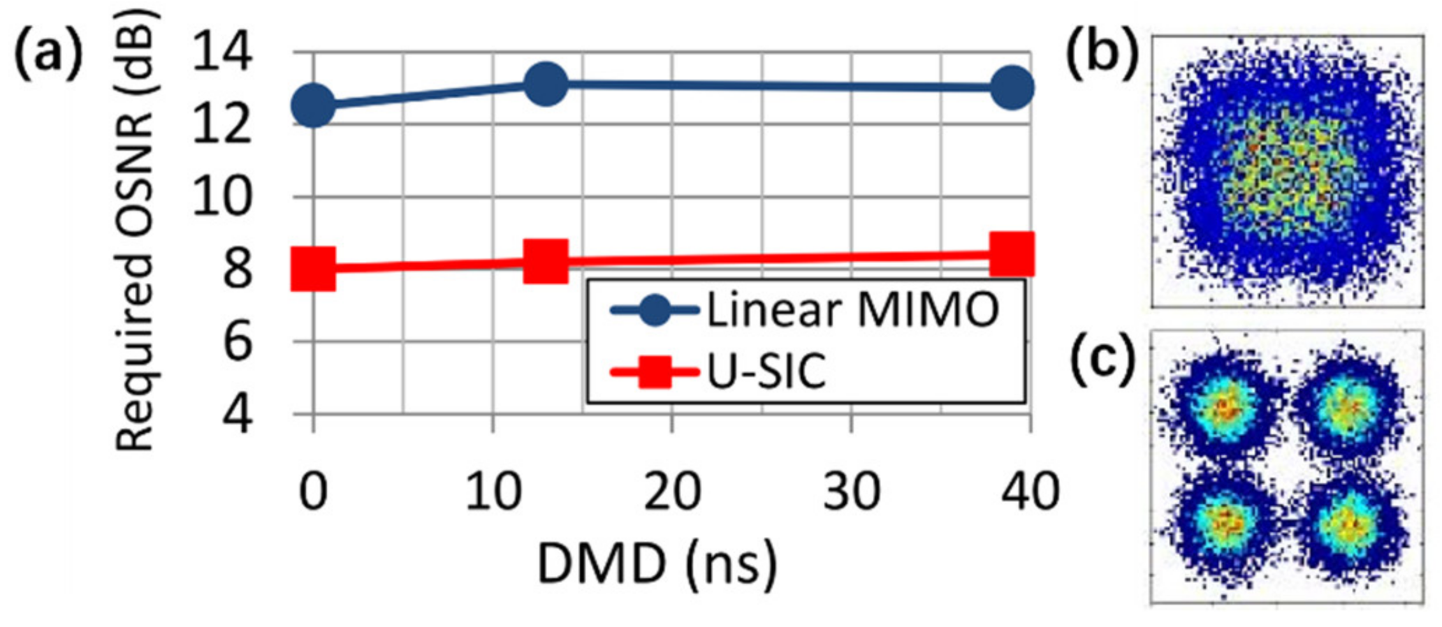
4.2. Interference Cancellation (IC)

Linear MIMO equalizers are also attractive to mitigate MDL effect because of its relative low complexity, adaptive schemes and high compatibility. The performance of these equalizers could be further enhanced by introducing more prior information of the channels which indicates that the SNR of each mode can be considered to utilize. Inspired by this idea, the interference from higher-SNR channels to the lower-SNR ones can be cancelled by equalizing stronger modes in advance. Each channel is equalized one by one from the highest- to the lowest-SNR modes by estimating the interference from other channels, which equalizer is called successive interference cancellation (SIC) schemes.
In order to realize longer-distance SDM transmission in [58,59], an unreplicated successive interference cancelling (U-SIC) equalizer that mitigates MDL-induced intermodal interference were proposed and successfully demonstrated. Through the corresponding experiments, an MDL tolerance improvement of 3.3 dB and an OSNR gain of >4.5 dB were demonstrated even under high DMGD up to 39 ns. As shown in Figure 10, as compared to the conventional SIC algorithm, channel estimation is no more required for the proposed U-SIC.
Figure 11 shows the advantages of U-SIC scheme on the improvement of Q factor and lower requirement of OSNR to achieve hard-decision (HD) forward error correction (FEC) (FEC) limit for bit error ratio (BER) in comparison with conventional linear MIMO algorithms. What’s more, in [60] the combination of U-SIC technique and mode scramblers enable the demonstration of the 2500-km long-haul MDM transmission with more than 2-dB Q-factor gain.
For higher performance in MDL-impaired MDM systems, a novel unreplicated parallel interference cancellation (U-PIC) scheme was proposed in [61] by increasing the number of iterations compared with U-SIC. By iterative utilization of the soft information of transmitted symbols from decoders, the U-PIC equalizer successfully cancel the MDL-induced intermodal interference among the channels with similar SNR. Experiment demonstrated that the U-PIC algorithm could achieve better performance than both the conventional linear MIMO equalizers and the above U-SIC algorithm.

4.3. Space-Time Coding Technique (STC)

A few studies have also shown that STC technique in transmitter can effectively suppress MDL effects in SDM systems, which was originally proposed to suppress spatial channel fading in wireless MIMO communications [62]. Instead of directly multiplexing different M modes to transmit independent symbols stream S M × 1 . MIMO scheme could be beneficial from the space and time degrees of freedom at once by making multiple copies of an input symbol over different channels at different time slots. Naturally, through various channel propagation, these copies could be exploited to have a better estimation of the transmitted symbols at receiver side and the MDL effect would be further mitigated. The schematic structure of SDM MIMO system applying STC technique is shown in Figure 12, where X M × T is a space-time transmitted codeword. Y M × T is the codeword at receiver side where M denotes the number of channels and T is the length of the code. N M × T denotes a white Gaussian noise.
The effectiveness of STC for MDL suppression in SDM systems has already been demonstrated by various simulations and subsequent experiments. In [63] and [64], it was shown that the combination of redundancy-free STC with inline mode scramblers and ML detector can thoroughly eliminate the SNR penalties caused by the MDL at most 10 dB. Moreover, two reduced-complexity STC detectors achieving a near-ML performance were also proposed: a sub-optimal decoding scheme and a multiblock STC approach in [64]. What’s more, two more simple schemes were proposed for STC applications to decrease coding complexity in SDM systems. In [65], Hadamard transform (HT) was utilized in STC technique to disperse the power of each symbol over all modes for identical channel equalization performance. Then, a dense 627-km SDM transmission experiment were demonstrated to prove the HT’s advantage of improving MDL tolerance, where the transmission distance was increased by 20%. While in [66], a mode-interleaving method was also presented to simplify STC schemes, which method could improve the transmission reach by 40% through simulation, as well as saving O M 2 computation complexity compared with conventional space-time block coding (STBC) method. The numerical conclusions of the benefits of STC were soon confirmed in [67] through experimental measurements, where lower BER at the same OSNR condition was achieved and the Q-factor in FMF transmission systems was improved by 3.4 dB in an absence of 10-dB MDL as shown in Figure 13a,b, respectively.
Since STC with mode scramblers was shown to be a powerful tool to mitigate MDL effect, more efforts were adopted to explore possible techniques for further improved performance of the SDM systems that apply STC technique. In [68], an upper bound of the error probability of the optical channel induced by MDL was derived, this upper bound leads to a design criterion of space-time codes which is able to totally mitigate MDL in SDM systems. In [69] and [70], the combination of STC and FEC was studied to suppress the MDL effect. Numerical simulation results showed that, through guidance of the aforementioned upper bound of error probability, the obtained gain of the combination is equal to the summation of both coding gain.
Moreover, the DSP techniques at the receiver for MDM systems were also widely studied to better suite with STC schemes. In [71] and [72], a STBC-aided RLS algorithm was developed for MDL mitigation in MDM systems to achieve quasi-RLS convergence speed as well as quasi-LMS complexity, with which assistance a 7.8 dB OSNR tolerance was obtained for polarization-division multiplexed (PDM) 64QAM system. In [73], a receiver-side linear decoding schemes was proposed for the orthogonal STBC-aided MDM system to achieve near-ML performance with reducing decoding complexity, which grows linearly with the order of constellations. In [74], a novel hybrid detection with combination of the IRS method and the decision feedback equalizer (DFE), was realized for the threaded algebraic space-time codes (TAST) assisted system, where the proposed detector achieved near-ML performance with a lower computational complexity.
We have concluded the above three DSP solutions for suppressing or mitigating MDL effect in Table 2 to help readers understand their advantages and disadvantages. As we can, see ML detector and IC techniques are receiver-side equalizers while STC is a transmitter-side coder technique which means it is easy to cooperate with other receiver-side solutions.

5. Novel DSP Techniques for MIMO Systems

With the fast improvement of data processing capacity, many novel DSP algorithms have been proposed in the last few years. This section focuses on the recent emerged DSP techniques for MIMO systems, including the extended DBP algorithm to handle nonlinear effects in FMFs, AI techniques to achieve MIMO equalization, and so on. In comparison with the conventional methods, these novel DSP algorithms have the potential to replace them for better performance.

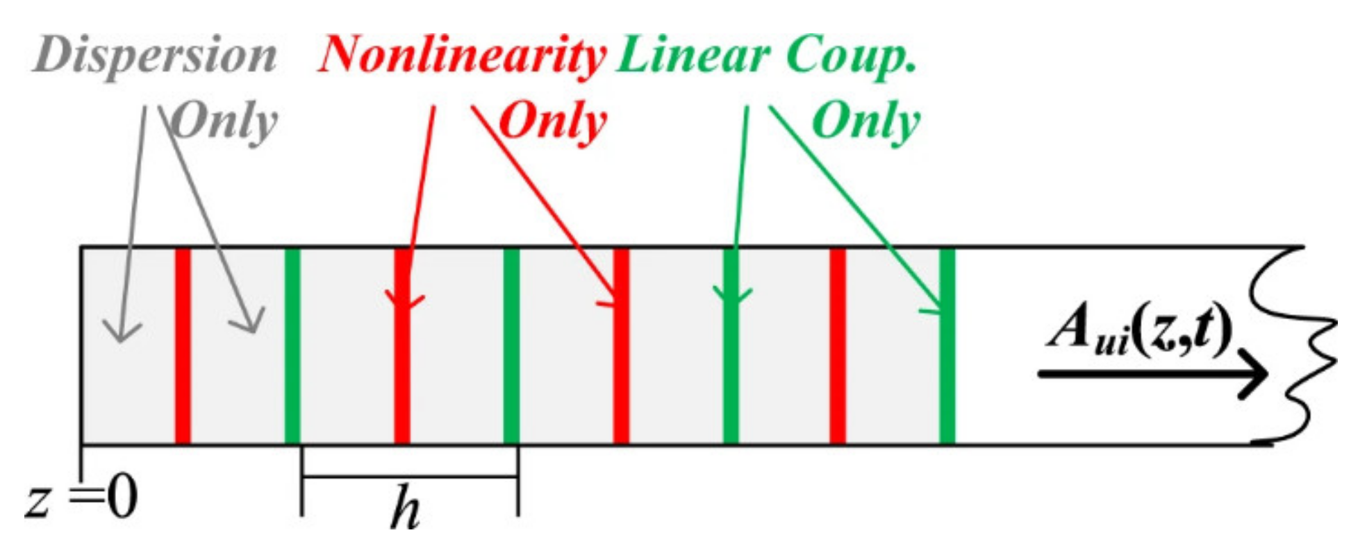
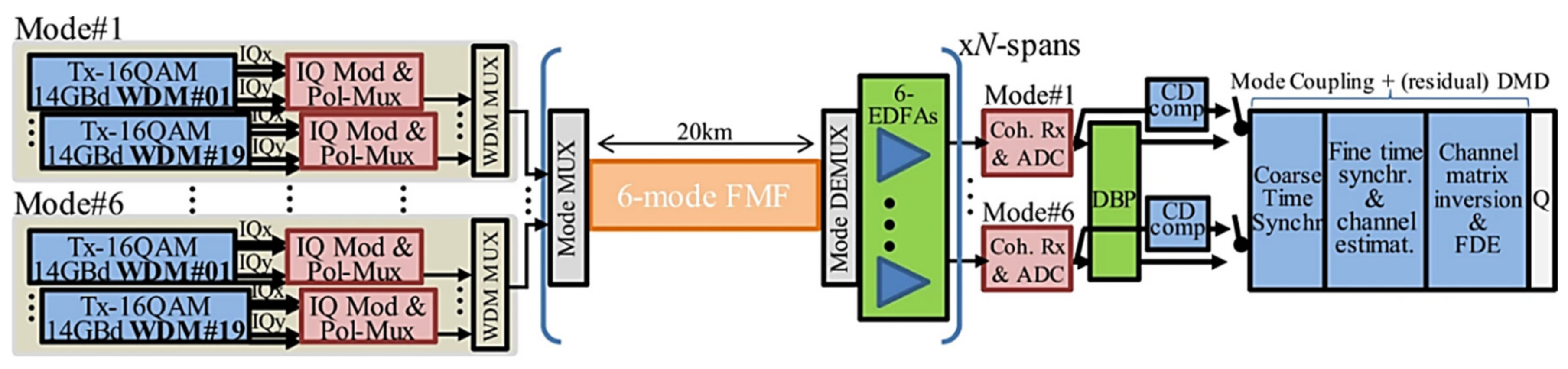
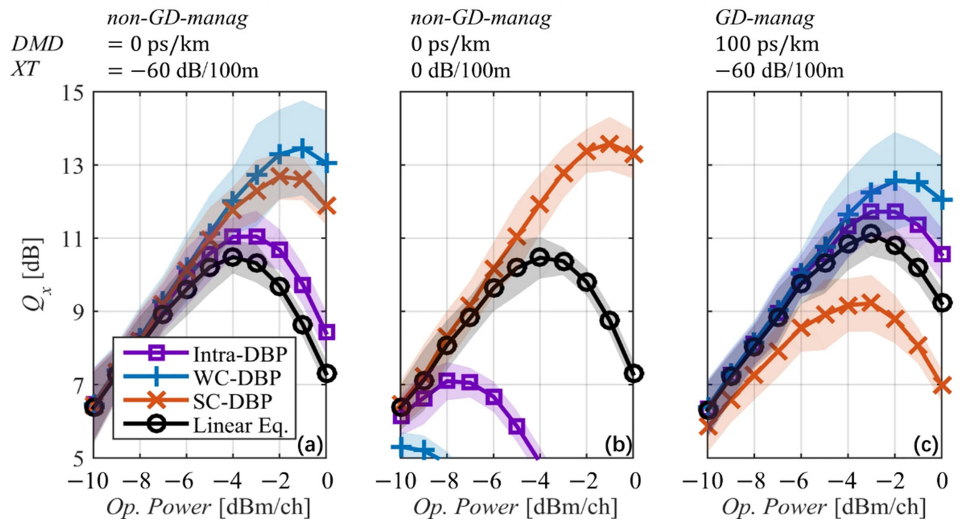
5.1. Digital Back-Propagation Algorithm (DBP)

It is well known to us that the DBP algorithm is the most common DSP method to compensate nonlinearities in single mode fiber. However, as mode coupling exists in FMFs, traditional DBP cannot be successfully used. The extension of single-mode split-step Fourier method (SSFM) based DBP has recently been proposed to solve the multimode propagation problem over FMFs [30,31]. As illustrated in Figure 14, a symmetric SSFM is implemented, where the nonlinear effects are considered in the middle of the segment instead of the segment boundary. By utilizing this structure, the generalized nonlinear Schrödinger equation (GNLSE) can be simplified according to the strength of the linear mode coupling.
Following the strategy above, two original Manakov-like equations with nonlinear coefficients are derived for FMFs in two extreme coupling regimes. In the weak coupling (WC) regime, we only need to consider the average value over birefringence fluctuations, which leads to a reduced intramodal degeneracy factor of 8/9 and a reduced intermodal degeneracy factor of 4/3 [75]. In the strong coupling (SC) regime, all propagation modes are included on average.
A 19 channels wavelength-division multiplexed (WDM) MDM system is simulated to study the performance as shown in Figure 15 [31]. There are six LP modes with dual-polarization in each channel, as 14 Gbaud polarization-multiplexed 16QAM, the overall data rate of 12.8 Tb/s is transmitted over 12 spans of 20 km 6-mode FMF. In the receiver side, DBP is implemented by utilizing a fixed step size of 100 m, subsequently, chromatic dispersion (CD) compensation, time synchronization, channel estimation is performed, and finally Q-factor is calculated.
Figure 16 shows the Q-factor performance with launched power in three different case. In Figure 16a, both WC-DBP and SC-DBP have a Q-factor improvement at low XT, which means that the Manakov approximations are reasonable. But it can be found that only SC-DBP can perform well at high XT shown in Figure 16b, which can be explained by the nonlinear coefficients in WC-DBP is larger than the actual channel leading to overcompensation. As shown in Figure 16c, when GD management with high DMD is utilized, WC-DBP can still perform well in low XT.
Recently, DBP is realized in a deep neural network architecture [32]. The architecture of this deep neural network (DNN) is shown in Figure 17, where the inputs are the received signal samples and the outputs are the estimated symbols. The weight W k represent linear effects in transmission, such as mode dependent loss and chromatic dispersion. And σ k is the nonlinear operator which represents the nonlinear phase derotation. A polarization rotation matrix R k is appended at the k-th stage of the DBP operation and can be optimized from training data without any knowledge of the principle states of polarization (PSP). Thus, all the linear and nonlinear parameters in traditional DBP can be optimized in the DNN.
The PDM-WDM transmission system is experimentally constructed to investigate the performance of this DNN [32]. The experiment setup is shown in Figure 18, where a 5 channel 50-GHz-spaced WDM system with 28 Gbaud 16-QAM modulation format is utilized. Ten fiber spans with different length are cascaded. At the receiver side, the signal is sampled and then processed in offline.
The Q factors of the center channel is shown in Figure 19a, it can be found that the DNN based DBP outperforms traditional DBP even in 1 step per span (StPS). Figure 19b shows the “M”-shaped amplitude responses of the filter, which exhibits some high-pass feature at the later staged in DNN. This phenomenon can be attributed to that the “M”-shaped filter tries to compensate an additional undesired term with a “∩” shaped spectrum. The optimized nonlinear coefficients with a “U” shape are shown in Figure 19c, which suggests that the nonlinear-phase derotation is larger in the middle stages than the beginning and end of the DBP. Figure 19d shows the optimized rotation angles for PSP, which agree with the theoretical expectation.

5.2. Artificial Intelligence (AI) Technology for MIMO Equalization

Recently, AI technologies have also attracted great interest in optical fiber communication, for its high excellent ability. Deep learning, as a main branch of AI, provides many neural network models to handle various optical communication problems. For example, artificial neural network (ANN) is widely utilized in nonlinear equalization [76,77,78] and optical performance monitoring [79,80], convolutional neural network (CNN) has the ability to get high accuracy of output images in MMF [81] and enabled high-spatial-density SDM framework [82]. And DNN, which is more complex than ANN, shows its excellent performance in end-to-end learning [83]. What’s more, the applications of deep learning in DSP bring a revolution in MIMO transmission systems. In this part, several neural networks are introduced to achieve MIMO equalization, and better performance can be obtained compared with the traditional methods.
As mentioned above, mode coupling is inevitable in MDM system which causes channel crosstalk and DMD. Thanks to deep learning, ANN can be used as a MIMO equalizer to mitigate these channel impairments [84]. A two mode MDM transmission system with an ANN equalizer is illustrated in Figure 20a, the ANN equalizer is placed at the receiver side and consists of three layers as depicted in Figure 20b. Meanwhile, a novel feed-forward and back propagation algorithm is employed to update the weight, in which the back propagation retrieved the feed-forward output as an input to the hidden layer.
Channel impulse response is analyzed to characterize the ANN performance. Figure 21a shows the input channel impulse response for two channels, in which both channels are coupled with each other significantly. Figure 21b,c are the target and output channel impulse response, respectively. There is a high similarity between these two pictures where the impulse response of both channels is separated clearly. Hence, this ANN equalizer has a good performance in compensating mode coupling and DMD.
Based on the fact that deep learning neural networks are highly nonlinear and have an ability to form arbitrarily nonlinear decision boundaries, a supervised deep learning neural network (DLNN) is employed in MIMO detection [85]. A schematic diagram is shown in Figure 22, where an MDM optical transmission system with N input modes and N output modes is adopted. At the receiver side, the received signals are fed to the DLNN to implement MIMO detection.
Figure 23 shows the detailed structure of the proposed DLNN. In this scheme, N complex signals are decomposed into the real parts and imaginary parts. And then, these 2N real signals are fed into a feed-forward neural network with M layers. For N × N MIMO system, 2N input neurons and 2N output neurons are required in the DLNN, which means that the complexity of DLNN increases with the polynomial time complexity of the MIMO dimension.
The performance of DLNN, traditional ZF detector and advanced Semi-Definite Relaxation Row-by-Row (SDR-RBR) is compared in a 2 × 2 MDM system. Figure 24 shows the BER curves versus channel condition number. It can be seen that DLNN has a better performance than the other two detectors with Q-factor greater than 15 dB.
It is generally known that the nonlinear Shannon limit has become the basic barrier of a channel maximum capacity in communication. To mitigate various nonlinear effects, DSP can be utilized. Recently, deep-learning-based MIMO equalization has been adopted to tackle the interplay of FWM interference and parametric amplified noise in coherent optical communication [86]. Meanwhile, inter-carrier crosstalk effects even without frequency stochastic variations can also be compensated by this novel MIMO neural network, which has hitherto been considered impossible.
In orthogonal frequency division Multiplexing (OFDM) system, the frequency dependent deterministic distortion leads to the center subcarriers suffering from higher nonlinear distortion than edge subcarriers, which leads to a lower signal-to-interference-plus-noise ratio (SINR). Consequently, as shown in Figure 25, a more complex ANN is employed in center subcarriers than edge subcarriers. Following this strategy, the SINR difference between each subcarrier is suppressed, resulting in a more robust equalization performance.
Figure 26 illustrates the structure of this mentioned equalizer. The hidden layer is adaptively adjusted by a set of electronic frequency sub-carriers which represent the third dimension of different frequencies. The complexity of this adaptive neural network depends on the hidden layers counts which is 3 or 4 and the modulation format level which is 4 for QPSK or 16 for 16-QAM. Therefore, compared with traditional methods, this 3D MIMO neural network will not increase the computational complexity.
In order to explore the performance of the MIMO deep learning equalization algorithm, as shown in Table 3, four different cases with different number of central subcarrier blocks were used for comparison. Figure 27a shows the result in a 3200-km QPSK WDM-CO-OFDM system, it can be seen that the performance under case 2 is better than the other three cases. And compared with the commercial single-carrier/polarization QPSK system for a 3200 km multi-channel configuration, the MIMO deep learning under case 2 brings a record 3.8-dB Q factor improvement. Such performance enhancement is maintained for a 2000-km single channel 16-QAM CO-OFDM system as is shown in Figure 27b.
In case 2, MIMO deep learning equalizer with traditional ANN and deterministic DBP in different transmission systems is compared: (a) WDM QPSK CO-OFDM at 3200 km and (b) Single channel 16-QAM CO-OFDM at 2000 km. It can be found from Figure 28a that compared with the ANN and DBP methods, at the optimal launched optical power (LOP) of −5 dBm, the Q-factor is improved by 1.4 dB and 2.1 dB, respectively. This is due to the fact that the DBP cannot accurately know the absolute position and relative spacing of the channels and subcarrier frequencies. From Figure 28b, it can be found that compared with linear equalization and ANN, the maximum allowable LOP of this MIMO equalizer is increased by 4 dB, and at the optimal LOP of 6 dBm, the Q factor 2.1 dB is improved in comparison to DBP.
In Table 4, different structures of neural network were summarized in terms of their respective applications in DSP techniques of MDM systems, which you could find that each type has its own speciality in mitigation of certain impairments in MDM links.

6. Conclusions

In this paper, we presented an overview of recent progress on advanced DSP techniques for MDM systems. Methodologies of digital approaches were reviewed that can mitigate the impact of MD, XT, MDL and nonlinearity on the system performance in long-haul MIMO-MDM transmissions. What’s more, AI technologies were also mentioned for its advantage to handle various optical communication problems, and we believe that machine learning would bring more possibilities on equalization, monitoring and characterization of MDM systems. In particular, the TV channels for MDM transmission also attract more attention in recent years, so our DSP techniques of FD-VFF RLS for MIMO-MDM systems were firstly reviewed to enlighten more works on tracking TV effect in FMF links.

Author Contributions

W.Y. planned and wrote the Section 1, Section 2, Section 3 and Section 4. G.P. planned and wrote Section 5. Z.Y. took the overall responsibility in managing the manuscript. Y.L. revised the whole article. L.Z. supervised the work and provided technical leadership. All co-authors contributed to the final version with suggestions and critical comments. All authors have read and agreed to the published version of the manuscript.

Funding

The work was supported by National Key R&D Program of China under grant 2019YFB2203902 and National Natural Science Foundation of China (NSFC) under Grant 61775165 and 61775164.

Institutional Review Board Statement

Not applicable.

Informed Consent Statement

Not applicable.

Data Availability Statement

Not applicable.

Acknowledgments

The authors would like to thank the anonymous reviewers for their valuable comments and suggestions to improve this manuscript.

Conflicts of Interest

The authors declare no conflict of interest.

References

  1. Richardson, D.J.; Fini, J.M.; Nelson, L.E. Space-division multiplexing in optical fibres. Nat. Photonics 2013, 7, 354–362. [Google Scholar] [CrossRef] [Green Version]
  2. Essiambre, R.; Tkach, R.W. Capacity trends and limits of optical communication networks. Proc. IEEE 2012, 100, 1035–1055. [Google Scholar] [CrossRef]
  3. Kitayama, K.-I.; Diamantopoulos, N.-P. Few-Mode Optical Fibers: Original Motivation and Recent Progress. IEEE Commun. Mag. 2017, 55, 163–169. [Google Scholar] [CrossRef]
  4. Puttnam, B.J.; Luis, R.S.; Klaus, W.; Sakaguchi, J.; Delgado Mendinueta, J.M.; Awaji, Y.; Wada, N.; Tamura, Y.; Hayashi, T.; Hirano, M.; et al. 2.15 Pb/s Transmission Using a 22 Core Homogeneous Single-mode Multi-core Fiber and Wideband Optical Comb. In Proceedings of the European Conference on Optical Communication (ECOC), Valencia, Spain, 27 September–1 October 2015. [Google Scholar]
  5. Rademacher, G.; Luis, R.S.; Puttnam, B.J.; Awaji, Y.; Wada, N. Crosstalk dynamics in multi-core fibers. Opt. Express 2017, 25, 12020–12028. [Google Scholar] [CrossRef] [PubMed]
  6. Ryf, R.; Fontaine, N.K.; Chang, S.H.; Alvarado, J.C.; Huang, B.; Antonio-Lopez, J.; Chen, H.; Essiambre, R.-J.; Burrows, E.; Tkach, R.W.; et al. Long-Haul Transmission over Multi-Core Fibers with Coupled Cores. In Proceedings of the European Conference on Optical Communication (ECOC), Gothenburg, Sweden, 17–21 September 2017. [Google Scholar]
  7. Inan, B.; Spinnler, B.; Ferreira, F.; van den Borne, D.; Lobato, A.; Adhikari, S.; Sleiffer, V.A.J.M.; Kuschnerov, M.; Hanik, N.; Jansen, S.L. DSP complexity of mode-division multiplexed receivers. Opt. Express 2012, 20, 10859–10869. [Google Scholar] [CrossRef] [PubMed] [Green Version]
  8. Pan, Z.; Weng, Y.; He, X.; Wang, J. Adaptive Frequency-domain Equalization and MIMO Signal Processing in Mode Division Multiplexing Systems Using Few-mode Fibers. In Proceedings of the Signal Processing in Photonic Communications (SPPCom), Vancouver, BC, Canada, 18–20 July 2016. [Google Scholar]
  9. Arik, S.O.; Askarov, D.; Kahn, J.M. Adaptive frequency-domain equalization in mode-division multiplexing systems. J. Lightwave Technol. 2014, 32, 1841–1852. [Google Scholar] [CrossRef]
  10. Faruk, M.S.; Kikuchi, K. Adaptive frequency-domain equalization in digital coherent optical receivers. Opt. Express 2011, 19, 12789–12798. [Google Scholar] [CrossRef] [PubMed] [Green Version]
  11. Yi, W.; Xuan, H.; Zhongqi, P. Performance Analysis of Low-complexity Adaptive Frequency-domain Equalization and MIMO Signal Processing for Compensation of Differential Mode Group Delay in Mode-division Multiplexing Communication Systems Using Few-mode Fibers. In Proceedings of the Next-Generation Optical Communication: Components, Sub-Systems and Systems V, San Francisco, CA, USA, 16–18 February 2016. [Google Scholar]
  12. Chen, Z.; Tran, A.V.; Do, C.C.; Simin, C.; Anderson, T.; Skafidas, E. Digital Signal Processing for Training-Aided Coherent Optical Single-Carrier Frequency-Domain Equalization Systems. J. Lightwave Technol. 2014, 32, 4110–4120. [Google Scholar] [CrossRef]
  13. Pittala, F.; Slim, I.; Mezghani, A.; Nossek, J.A. Training-aided frequency-domain channel estimation and equalization for single-carrier coherent optical transmission systems. J. Lightwave Technol. 2014, 32, 4247–4261. [Google Scholar] [CrossRef]
  14. Xuan, H.; Yi, W.; Junyi, W.; Pan, Z. Noise Power Directed Adaptive Frequency Domain Least Mean Square Algorithm with Fast Convergence for DMGD Compensation in Few-mode Fiber Transmission Systems. In Proceedings of the Optical Fiber Communications Conference and Exhibition (OFC), San Francisco, CA, USA, 9–13 March 2014. [Google Scholar]
  15. Puttnam, B.J.; Sakaguchi, J.; Mendinueta, J.M.D.; Klaus, W.; Awaji, Y.; Wada, N.; Kanno, A.; Kawanishi, T. Investigating self-homodyne coherent detection in a 19 channel space-division-multiplexed transmission link. Opt. Express 2013, 21, 1561–1566. [Google Scholar] [CrossRef]
  16. Yi, W.; Ting, W.; Zhongqi, P. Fast-convergent Adaptive Frequency-domain Recursive Least-squares Algorithm with Reduced Complexity for MDM Transmission Systems Using Optical Few-mode Fibers. In Proceedings of theConference on Lasers and Electro-Optics (CLEO), San Jose, CA, USA, 5–10 June 2016. [Google Scholar]
  17. Xi, C.; Jiayuan, H.; An, L.; Jia, Y.; Shieh, W. Characterization of Dynamic Evolution of Channel Matrix in Two-mode Fibers. In Proceedings of the OFC Collocated National Fiber-Optic Engineers’ Conference (OFC/NFOEC), Anaheim, CA, USA, 17–21 March 2013. [Google Scholar]
  18. Chen, X.; He, J.; Li, A.; Ye, J.; Shieh, W. Characterization and analysis of few-mode fiber channel dynamics. IEEE Photonics Technol. Lett. 2013, 25, 1819–1822. [Google Scholar] [CrossRef]
  19. Hu, Q.; Chen, X.; Shieh, W. Comparison of Channel Fluctuation Between Single-mode Fibers and Few-mode Fibers Using Stokes-space Analysis. In Proceedings of the OptoElectronics and Communications Conference (OECC) and Australian Conference on Optical Fibre Technology (ACOFT), Melbourne, VIC, Australia, 6–10 July 2014. [Google Scholar]
  20. Warm, S.; Petermann, K. Splice loss requirements in multi-mode fiber mode-division-multiplex transmission links. Opt. Express 2013, 21, 519–532. [Google Scholar] [CrossRef] [PubMed]
  21. Krummrich, P.M. Optical amplification and optical filter based signal processing for cost and energy efficient spatial multiplexing. Opt. Express 2011, 19, 16636–16652. [Google Scholar] [CrossRef] [PubMed]
  22. Cocq, G.L.; Quiquempois, Y.; Rouge, A.L.; Bouwmans, G.; El Hamzaoui, H.; Delplace, K.; Bouazaoui, M.; Bigot, L. Few mode Er3+-doped fiber with micro-structured core for mode division multiplexing in the C-band. Opt. Express 2013, 21, 31646–31659. [Google Scholar] [CrossRef]
  23. Ryf, R.; Fontaine, N.K.; Dunayevsky, J.; Sinefeld, D.; Blau, M.; Montoliu, M.; Randel, S.; Liu, C.; Ercan, B.; Esmaeelpour, M.; et al. Wavelength-selective Switch for Few-mode Fiber Transmission. In Proceedings of the European Conference and Exhibition on Optical Communication (ECOC), London, UK, 22–26 September 2013. [Google Scholar]
  24. Winzer, P.J.; Foschini, G.J. MIMO capacities and outage probabilities in spatially multiplexed optical transport systems. Opt. Express 2011, 19, 16680–16696. [Google Scholar] [CrossRef]
  25. Ip, E.; Milione, G.; Huang, Y.-K.; Wang, T. Impact of Mode-dependent Loss on Long-haul Transmission Systems Using Few-mode Fibers. In Proceedings of the Optical Fiber Communications Conference and Exhibition (OFC), Anaheim, CA, USA, 20–24 March 2016. [Google Scholar]
  26. Xuan, H.; Yi, W.; Zhongqi, P. A Step-Size Controlled Method for Fast Convergent Adaptive FD-LMS Algorithm in Few-Mode Fiber Communication Systems. J. Lightwave Technol. 2014, 32, 3820–3826. [Google Scholar] [CrossRef]
  27. Rademacher, G.; Petermann, K. Nonlinear Gaussian Noise Model for Multimode Fibers with Space-Division Multiplexing. J. Lightwave Technol. 2016, 34, 2280–2287. [Google Scholar] [CrossRef]
  28. Essiambre, R.-J.; Mestre, M.A.; Ryf, R.; Gnauck, A.H.; Tkach, R.W.; Chraplyvy, A.R.; Sun, Y.; Jiang, X.; Lingle, R. Experimental investigation of inter-modal four-wave mixing in few-mode fibers. IEEE Photonics Technol. Lett. 2013, 25, 539–542. [Google Scholar] [CrossRef]
  29. Antonelli, C.; Shtaif, M.; Mecozzi, A. Modeling of nonlinear propagation in space-division multiplexed fiber-optic transmission. J. Lightwave Technol. 2016, 34, 36–54. [Google Scholar] [CrossRef]
  30. Ferreira, F.M.; Costa, C.S.; Sygletos, S.; Ellis, A.D. Nonlinear Compensation Using Digital Back-Propagation in Few-Mode Fibre Spans with Intermediate Coupling. In Proceedings of the European Conference on Optical Communication (ECOC), Gothenburg, Sweden, 17–21 September 2017. [Google Scholar]
  31. Ferreira, F.M.; Costa, C.S.; Sygletos, S.; Ellis, A.D. Overcoming degradation in spatial multiplexing systems with stochastic nonlinear impairments. Sci. Rep. 2018, 8, 1–10. [Google Scholar] [CrossRef]
  32. Fan, Q.; Zhou, G.; Gui, T.; Lu, C.; Lau, A.P.T. Advancing theoretical understanding and practical performance of signal processing for nonlinear optical communications through machine learning. Nat. Commun. 2020, 11, 1–11. [Google Scholar] [CrossRef]
  33. Lobato, A.; Ferreira, F.; Inan, B.; Adhikari, S.; Kuschnerov, M.; Napoli, A.; Spinnler, B.; Lankl, B. Maximum-Likelihood Detection in Few-Mode Fiber Transmission With Mode-Dependent Loss. IEEE Photonics Technol. Lett. 2013, 25, 1095–1098. [Google Scholar] [CrossRef]
  34. Xi, C.; Jia, Y.; Yue, X.; An, L.; Jiayuan, H.; Qian, H.; Shieh, W. Equalization of Two-mode Fiber Based MIMO Signals with Larger Receiver Sets. In Proceedings of the European Conference and Exhibition on Optical Communications (ECOC), Amsterdam, Netherlands, 16–20 September 2012. [Google Scholar]
  35. Randel, S.; Ryf, R.; Sierra, A.; Winzer, P.J.; Gnauck, A.H.; Bolle, C.A.; Essiambre, R.-J.; Peckham, D.W.; McCurdy, A.; Lingle, R. 6 × 56-Gb/s mode-division multiplexed transmission over 33-km few-mode fiber enabled by 6×6 MIMO equalization. Optics Express 2011, 19, 16697–16707. [Google Scholar] [CrossRef] [PubMed]
  36. Randel, S.; Winzer, P.J.; Montoliu, M.; Ryf, R. Complexity Analysis of Adaptive Frequency-Domain Equalization for MIMO-SDM Transmission. In Proceedings of the European Conference and Exhibition on Optical Communication (ECOC), Stevenage, UK, 22–26 September 2013. [Google Scholar]
  37. Neng, B.; Guifang, L. Adaptive Frequency-domain Equalization for Mode-division Multiplexed Transmission. IEEE Photonics Technol. Lett. 2012, 24, 1918–1921. [Google Scholar] [CrossRef]
  38. Zhou, X.; Wang, J.; Weng, Y.; Pan, Z. A Fast Convergence Frequency Domain Least Mean Square Algorithm for Compensation of Differential Mode Group Delay in Few Mode Fibers. In Proceedings of the Optical Fiber Communication Conference, Anaheim, CA, USA, 17–21 March 2013. [Google Scholar]
  39. Kudo, R.; Kobayashi, T.; Ishihara, K.; Takatori, Y.; Sano, A.; Miyamoto, Y. Coherent optical single carrier transmission using overlap frequency domain equalization for long-haul optical systems. J. Lightwave Technol. 2009, 27, 3721–3728. [Google Scholar] [CrossRef]
  40. Li, G.; Bai, N.; Zhao, N.; Xia, C. Space-division multiplexing: The next frontier in optical communication. Adv. Opt. Photonics 2014, 6, 413–487. [Google Scholar] [CrossRef] [Green Version]
  41. Yang, Z.; Zhao, J.; Bai, N.; Ip, E.; Wang, T.; Li, G. Experimental Demonstration of Adaptive Recursive Least Square Frequency-domain Equalization for Long-distance Mode-division Multiplexed Transmission. In Proceedings of the European Conference on Optical Communication (ECOC), Valencia, Spain, 27 September–1 October 2015. [Google Scholar]
  42. Fontaine, N.K.; Ryf, R.; Chen, H.; Benitez, A.V.; Amezcua-Correa, R. 30 × 30 MIMO Transmission over 15 Spatial Modes. In Proceedings of the Optical Fiber Communicaiton Conference (OFC), Los Angeles, CA, USA, 24–26 March 2015. [Google Scholar]
  43. Benvenuto, N.; Cherubini, G.; Tomasin, S. Algorithms for Communications Systems and Their Applications; Wiley Online Library: Hoboken, NJ, USA, 2002; pp. 197–203. [Google Scholar]
  44. Paleologu, C.; Benesty, J.; Ciochina, S. A robust variable forgetting factor recursive least-squares algorithm for system identification. IEEE Signal Process. Lett. 2008, 15, 597–600. [Google Scholar] [CrossRef]
  45. Wang, J. A Variable Forgetting Factor RLS Adaptive Filtering Algorithm. In Proceedings of the IEEE International Symposium on Microwave, Antenna, Propagation and EMC Technologies for Wireless Communications (MAPE), Beijing, China, 27–29 October 2009. [Google Scholar]
  46. Park, D.J.; Jun, B.E.; Kim, J.H. Fast tracking RLS algorithm using novel variable forgetting factor with unity zone. Electron. Lett. 1991, 27, 2150–2151. [Google Scholar] [CrossRef]
  47. Yang, Z.; Zhao, J.; Bai, N.; Ip, E.; Wang, T.; Li, Z.; Li, G. Experimental demonstration of adaptive vff-rls-fde for long-distance mode-division multiplexed transmission. Opt. Express 2018, 26, 18362–18367. [Google Scholar] [CrossRef]
  48. Choutagunta, K.; Ryf, R.; Fontaine, N.; Wittek, S.; Alvarado-Zacarias, J.C.; Mazur, M.; Haoshuo, C.; Essiambre, R.J.; Amezcua-Correa, R.; Hayashi, T.; et al. Modal Dynamics in Spatially Multiplexed Links. In Proceedings of the Optical Fiber Communications Conference and Exhibition (OFC), San Diego, CA, USA, 3–7 March 2019. [Google Scholar]
  49. Wenbo, Y.; Zhiqun, Y.; Xutao, W.; Lin, Z.; Guifang, L. Frequency-Domain VFF-RLS Equalization for the Time-Varying Mode-Division Multiplexed Channels. In Proceedings of the Conference on Lasers and Electro-Optics (CLEO), San Jose, CA, USA, 10–15 May 2020. [Google Scholar]
  50. Leung, S.-H.; So, C.F. Gradient-based variable forgetting factor RLS algorithm in time-varying environments. IEEE Trans. Signal Process. 2005, 53, 3141–3150. [Google Scholar] [CrossRef]
  51. Jankiraman, M. Space-Time Codes and MIMO Systems; Artech House: Fitchburg, MA, USA, 2004; pp. 22–23. [Google Scholar]
  52. Shibahara, K.; Mizuno, T.; Lee, D.; Miyamoto, Y. Advanced MIMO Signal Processing Techniques Enabling Long-Haul Dense SDM Transmissions. J. Lightwave Technol. 2018, 36, 336–348. [Google Scholar] [CrossRef]
  53. Lobato, A.; Ferreira, F.; Rabe, J.; Inan, B.; Adhikari, S.; Kuschnerov, M.; Napoli, A.; Spinnler, B.; Lankl, B. On the Mode-dependent Loss Compensation for Mode-division Multiplexed Systems. In Proceedings of the 15th International Conference on Transparent Optical Networks (ICTON), Cartagena, Spain, 23–27 June 2013. [Google Scholar]
  54. Biglieri, E.; Calderbank, R.; Constantinides, A.; Goldsmith, A.; Paulraj, A.; Poor, H.V. MIMO Wireless Communications; Cambridge University Press: Cambridge, UK, 2007; pp. 186–190. [Google Scholar]
  55. Lobato, A.; Chen, Y.; Jung, Y.; Chen, H.; Inan, B.; Kuschnerov, M.; Fontaine, N.K.; Ryf, R.; Spinnler, B.; Lankl, B. 12-mode OFDM transmission using reduced-complexity maximum likelihood detection. Opt. Lett. 2015, 40, 328–331. [Google Scholar] [CrossRef] [PubMed]
  56. Lobato, A.; Rabe, J.; Ferreira, F.; Kuschnerov, M.; Spinnler, B.; Lankl, B. Near-ML detection for MDL-impaired few-mode fiber transmission. Opt. Express 2015, 23, 9589–9601. [Google Scholar] [CrossRef] [PubMed]
  57. Li, L.; Tian, Z.; Guijun, H. Complex lattice reduction aided detection for mode-division multiplexing systems with mode dependent loss and differential mode group delay. Opt. Commun. 2019, 442, 65–70. [Google Scholar] [CrossRef]
  58. Shibahara, K.; Mizuno, T.; Miyamoto, Y. LDPC-coded FMF Transmission Employing Unreplicated Successive Interference Cancellation for MDL-Impact Mitigation. In Proceedings of the European Conference on Optical Communication (ECOC), Gothenburg, Sweden, 17–21 September 2017. [Google Scholar]
  59. Shibahara, K.; Mizuno, T.; Miyamoto, Y. Interference Cancelling Techniques for Long-haul MIMO-SDM Transmission. In Proceedings of the Signal Processing in Photonic Communications (SPPCom), Zurich, Switzerland, 2–5 July 2018. [Google Scholar]
  60. Shibahara, K.; Mizuno, T.; Doohwan, L.; Miyamoto, Y.; Ono, H.; Nakajima, K.; Amma, Y.; Takenaga, K.; Saitoh, K. DMD-Unmanaged Long-Haul SDM Transmission Over 2500-km 12-Core 3-Mode MC-FMF and 6300-km 3-Mode FMF Employing Intermodal Interference Canceling Technique. J. Lightwave Technol. 2019, 37, 138–147. [Google Scholar] [CrossRef]
  61. Shibahara, K.; Mizuno, T.; Doohwan, L.; Miyamoto, Y.; Ono, H.; Nakajima, K.; Amma, Y.; Takenaga, K.; Saitoh, K. Iterative unreplicated parallel interference canceler for MDL-tolerant dense SDM (12-Core 3-Mode) transmission over 3000 km. J. Lightwave Technol. 2019, 37, 1560–1569. [Google Scholar] [CrossRef]
  62. Tarokh, V.; Seshadri, N.; Calderbank, A.R. Space-time codes for high data rate wireless communication: Performance criterion and code construction. IEEE Trans. Inf. Theory 2002, 44, 744–765. [Google Scholar] [CrossRef] [Green Version]
  63. Awwad, E.; Othman, G.R.B.; Jaouen, Y. Space-time Coding and Optimal Scrambling for Mode Multiplexed Optical Fiber Systems. In Proceedings of the IEEE International Conference on Signal Processing for Communications (ICC), London, UK, 8–12 June 2015. [Google Scholar]
  64. Awwad, E.; Othman, G.R.B.; Jaouen, Y. Space-Time Coding Schemes for MDL-Impaired Mode-Multiplexed Fiber Transmission Systems. J. Lightwave Technol. 2015, 33, 5084–5094. [Google Scholar] [CrossRef]
  65. Shibahara, K.; Mizuno, T.; Takara, H.; Kawakami, H.; Lee, D.; Miyamoto, Y.; Matsuo, S.; Saitoh, K.; Yamada, M. Space-time Coding-assisted Transmission for Mitigation of MDL Impact on Mode-division Multiplexed Signals. In Proceedings of the Optical Fiber Communications Conference and Exhibition (OFC), Anaheim, CA, USA, 20–24 March 2016. [Google Scholar]
  66. Yingchao, X.; Yu, T.; Bo, H.; Han, Y.; Juhao, L.; Paikun, Z.; Yongqi, H.; Zhangyuan, C. Mode-Interleaving Method with Improved Transmission Reach for MDL-Impaired MDM Systems. In Proceedings of the Asia Communications and Photonics Conference (ACP), Wuhan, China, 2–5 November 2016. [Google Scholar]
  67. Amhoud, E.M.; Othman, G.R.B.; Bigot, L.; Mengdi, S.; Andresen, E.R.; Labroille, G.; Bigot-Astruc, M.; Jaouen, Y. Experimental Demonstration of Space-Time Coding for MDL Mitigation in Few-Mode Fiber Transmission Systems. In Proceedings of the European Conference on Optical Communication (ECOC), Gothenburg, Sweden, 17–21 September 2017. [Google Scholar]
  68. Amhoud, E.M.; Othman, G.R.B.; Jaouen, Y. Design Criterion of Space-time Codes for SDM Optical Fiber Systems. In Proceedings of the International Conference on Telecommunications (ICT), Thessaloniki, Greece, 16–18 May 2016. [Google Scholar]
  69. Amhoud, E.M.; Jaouen, Y.; Ben-Othman, G.R. Joint Space-time Coding and FEC for MDL Mitigation in Few-mode Fiber Systems. In Proceedings of the Novel Optical Materials and Applications (NOMA), Vancouver, BC, Canada, 18–20 July 2016. [Google Scholar]
  70. Amhoud, E.M.; Othman, G.R.B.; Jaouen, Y. Concatenation of Space-Time Coding and FEC for Few-Mode Fiber Systems. IEEE Photonics Technol. Lett. 2017, 29, 603–606. [Google Scholar] [CrossRef]
  71. Yi, W.; Xuan, H.; Junyi, W.; Zhongqi, P. Rigorous Study of Low-complexity Adaptive Space-time Block-coded MIMO Receivers in High-speed Mode Multiplexed Fiber-optic Transmission Links Using Few-mode Fibers. In Proceedings of the Next-Generation Optical Communication: Components, Sub-Systems and Systems VI, San Francisco, CA, USA, 31 January–2 February 2017. [Google Scholar]
  72. Yi, W.; Xuan, H.; Wang, Y.; Pacheco, M.C.; Junyi, W.; Pan, Z. Mode-dependent Loss Mitigation Scheme for PDM-64QAM Few-Mode Fiber Space-division-multiplexing Systems via STBC-MIMO Equalizer. In Proceedings of the Conference on Lasers and Electro-Optics (CLEO), San Jose, CA, USA, 14–19 May 2017. [Google Scholar]
  73. Yong Qiang, H.; Wen Tao, L.; Xiao Chuan, X.; Chen, R.T. Orthogonal STBC for MDL mitigation in mode division multiplexing system with MMSE channel estimation. J. Lightwave Technol. 2017, 35, 1858–1867. [Google Scholar]
  74. Yongqiang, H.; Li, L.; Weiting, S.; Guangming, S.; Huaxi, G. Hybrid IRS and DFE Detection Scheme for MDL-impaired Transmission with TAST Coding. J. Lightwave Technol. 2019, 37, 4251–4259. [Google Scholar]
  75. Mumtaz, S.; Essiambre, R.-J.; Agrawal, G.P. Nonlinear Propagation in Multimode and Multicore Fibers: Generalization of the Manakov Equations. J. Lightwave Technol. 2013, 31, 398–406. [Google Scholar] [CrossRef] [Green Version]
  76. Giacoumidis, E.; Le, S.T.; Ghanbarisabagh, M.; McCarthy, M.; Aldaya, I.; Mhatli, S.; Jarajreh, M.A.; Haigh, P.A.; Doran, N.J.; Ellis, A.D.; et al. Fiber nonlinearity-induced penalty reduction in CO-OFDM by ANN-based nonlinear equalization. Opt. Lett. 2015, 40, 5113–5116. [Google Scholar] [CrossRef] [PubMed]
  77. Siming, L.; Alfadhli, Y.M.; Shuyi, S.; Mu, X.; Huiping, T.; Gee-Kung, C. A Novel ANN Equalizer to Mitigate Nonlinear Interference in Analog-RoF Mobile Fronthaul. IEEE Photonics Technol. Lett. 2018, 30, 1675–1678. [Google Scholar]
  78. Caballero, F.J.V.; Ives, D.J.; Laperle, C.; Charlton, D.; Zhuge, Q.; O’Sullivan, M.; Savory, S.J. Machine learning based linear and nonlinear noise estimation. J. Opt. Commun. Netw. 2018, 10, D42–D51. [Google Scholar] [CrossRef]
  79. Huang, Y.; Chen, Y.X.; Yu, J. Optical Performance Monitoring of 56Gbps Optical PAM4 Signal Using Artificial Neural Networks. In Proceedings of the Asia Communications and Photonics Conference (ACPC), Guangzhou, Guangdong, China, 10–13 November 2017. [Google Scholar]
  80. Yu, Z.; Wan, Z.; Shu, L.; Hu, S.; Zhao, Y.; Zhang, J.; Xu, K. Loss weight adaptive multi-task learning based optical performance monitor for multiple parameters estimation. Opt. Express 2019, 27, 37041–37055. [Google Scholar] [CrossRef]
  81. Rahmani, B.; Loterie, D.; Konstantinou, G.; Psaltis, D.; Moser, C. Multimode optical fiber transmission with a deep learning network. Light-Sci. Appl. 2018, 7, 69. [Google Scholar] [CrossRef]
  82. Fan, P.; Ruddlesden, M.; Wang, Y.; Zhao, L.; Lu, C.; Su, L. Learning Enabled Dense Space-division Multiplexing through a Single Multimode Fibre. arXiv 2020, arXiv:2002.01788, preprint. [Google Scholar]
  83. Karanov, B.; Chagnon, M.; Thouin, F.; Eriksson, T.A.; Bulow, H.; Lavery, D.; Bayvel, P.; Schmalen, L. End-to-End Deep Learning of Optical Fiber Communications. J. Lightwave Technol. 2018, 36, 4843–4855. [Google Scholar] [CrossRef]
  84. Fazea, Y.; Sajat, M.S.; Ahmad, A.; Alobaedy, M.M. Channel Optimization in Mode Division Multiplexing Using Neural Networks. In Proceedings of the IEEE International Colloquium on Signal Processing and Its Applications (CSPA), Batu Feringghi, Malaysia, 9–10 March 2018. [Google Scholar]
  85. Poudel, B.; Oshima, J.; Kobayashi, H.; Iwashita, K. MIMO detection using a deep learning neural network in a mode division multiplexing optical transmission system. Opt. Commun. 2019, 440, 41–48. [Google Scholar] [CrossRef]
  86. Giacoumidis, E.; Wei, J.; Aldaya, I.; Barry, L.P. Exceeding the Nonlinear Shannon-Limit in Coherent Optical Communications by MIMO Machine Learning. arXiv 2018, arXiv:1802.09120. [Google Scholar]
Figure 1. Block diagram of the proposed FDE for one mode channel.
Applsci 11 01363 g001
Figure 2. Number of multiplies per symbol vs. filter tap length for TDE and FDE. FDE can significantly reduce the computational complexity (m = 10).
Applsci 11 01363 g002
Figure 3. Complexity ratio of FD-RLS and FD-LMS.
Applsci 11 01363 g003
Figure 4. Block diagram of the RLS FDE.
Applsci 11 01363 g004
Figure 5. Convergence speed comparison between VFF-RLS/RLS and LMS: (a) MSE convergence at 600-km vs. symbols; (b) Ratio of convergence speed of LMS and VFF-RLS/RLS vs. Distance.
Applsci 11 01363 g005
Figure 6. Block diagram of the FD-VFF-RLS algorithm.
Applsci 11 01363 g006
Figure 7. Mean Q2 factor vs. rotational angular frequency for different algorithm: (a) A lower steady-state misalignment with a poorer tracking capability; (b) A higher steady-state misalignment with a better tracking capability.
Applsci 11 01363 g007
Figure 8. (a) OSNR penalty vs. distance and (b) normalized histogram of the OSNR penalty (320 km) for weakly and strongly coupled modes, MMSE equalizer and ML detection, 200 channel realizations.
Applsci 11 01363 g008
Figure 9. Number of complex multiplications per bit as a function of the number of tributaries NT for the MMSE equalizer, IRSML and ML detector for different modulation formats.
Applsci 11 01363 g009
Figure 10. Schematic structures of U-SIC detectors comprising two stages.
Applsci 11 01363 g010
Figure 11. (a) Required OSNR to achieve HD-FEC limit BER under FMF links with various DMD values. And LP11a-X signals detected through a linear MIMO equalization (b) or through a U-SIC scheme (c) after transmission over 15-km FMF at OSNR of 8 dB.
Applsci 11 01363 g011
Figure 12. SDM transmission system with STC technique.
Applsci 11 01363 g012
Figure 13. (a) BER vs. OSNR for ST coded and uncoded transmission for MDL = 0, 6, 10 dB (b). Q penalty vs. MDL at OSNR = 14 dB with regards to the MDL-free transmission.
Applsci 11 01363 g013
Figure 14. The symmetric SSFM for FMFs with linear coupling.
Applsci 11 01363 g014
Figure 15. Simulated WDM-MDM system based on new DBP.
Applsci 11 01363 g015
Figure 16. Q factor vs. launched power per channel in three different cases. (a) low XT and DMD free; (b) high XT and DMD free; (c) low XT and high DMD with GD-managed.
Applsci 11 01363 g016
Figure 17. The architecture of DNN to implement DBP and PSP derotation.
Applsci 11 01363 g017
Figure 18. Experiment setup for PDM-WDM system.
Applsci 11 01363 g018
Figure 19. Transmission results for PDM-WDM system. (a) Q-factors vs. launch power in different algorithm; (b) Optimized amplitude spectra after linear operation in different fiber segment; (c) Optimized nonlinear coefficients in different fiber segment; (d) Optimized rotation angle for PSP.
Applsci 11 01363 g019
Figure 20. (a) MDM transmission system with ANN equalizer; (b) The structure of ANN.
Applsci 11 01363 g020
Figure 21. (a) Input channel impulse response; (b) Target channel impulse response; (c) Output channel impulse response.
Applsci 11 01363 g021
Figure 22. MDM transmission system based on DLNN.
Applsci 11 01363 g022
Figure 23. The structure of DLNN.
Applsci 11 01363 g023
Figure 24. The BER performance of DLNN, ZF and SDR-RBR.
Applsci 11 01363 g024
Figure 25. Conceptual diagram of the neural network-based MIMO equalization strategy.
Applsci 11 01363 g025
Figure 26. The architecture of MIMO deep learning equalizer.
Applsci 11 01363 g026
Figure 27. Transmission performance of MIMO equalizer in different cases. (a) WDM QPSK CO-OFDM at 3200 km; (b) single-channel 16 QAM CO-OFDM at 2000 km.
Applsci 11 01363 g027
Figure 28. Transmission performance comparison among MIMO deep leaning, ANN and deterministic DBP. (a) WDM QPSK CO-OFDM at 3200 km; (b) single-channel 16-QAM CO-OFDM at 2000 km.
Applsci 11 01363 g028
Table 1. Complexity comparison between the FD-RLS and FD-LMS.
OperationNumber of Complex Multiplications
LMSRLS
Compute output 4 m 4 m
Update filter coef. 4 m 4 m
FFT/IFFT ( 4 + 4 m ) log 2 N f ( 4 + 4 m ) log 2 N f
Update Kalman vector- 8 + 4 m
Update correlation matrix- 12 m
Table 2. Comparison between different digital solutions for mitigating MDL effect.
ClassificationReceiver-SideTransmitter-Side
NameMLICSTC
ComplexityHighLowModerate (excluding equalizer)
AdvantagesOptimal equalizerSuboptimal equalizerEasily compatible with other solutions; Coder technique
DisadvantagesHigh complexityWorse performanceLoss of multiplexing gain; Required for extra coder and equalizer
Table 3. Different cases of block-size for middle subcarriers and number of hidden layers.
CasesBlock-Size for Middle SubcarriersHidden Layers
1503
21003
31503
42 × 54 (middle groups), 2 × 51 (edge groups)4
Table 4. Applications of neural network in MIMO system.
Structures of NNApplications
ANNCompensating mode coupling and DMD
DLNNMIMO detection
3D-ANNMIMO equalization in the presence of FWM
Publisher’s Note: MDPI stays neutral with regard to jurisdictional claims in published maps and institutional affiliations.

