Piston Rod Coating Material Study of Reciprocating Sealing Experiment Based on Sterling Seal

Abstract
:1. Introduction
2. Materials and Methods
2.1. Materials
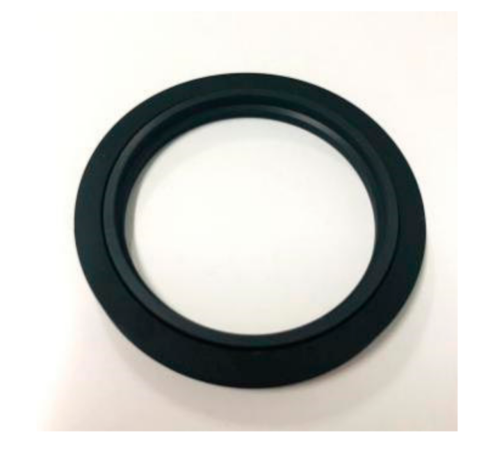
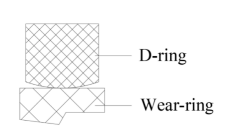
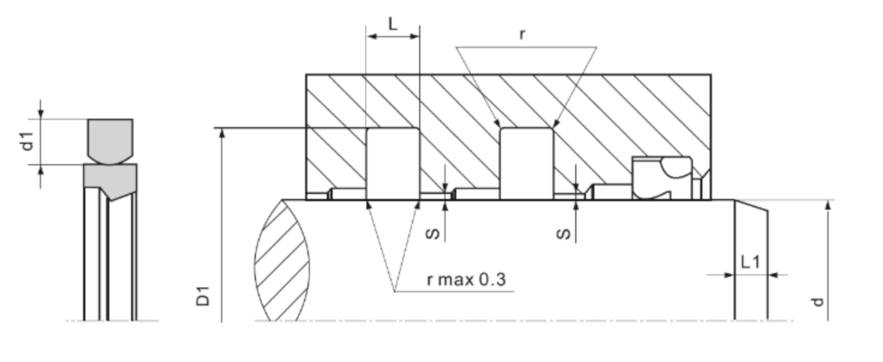
2.1.1. Seals
2.1.2. Piston Rod
2.1.3. Lubricating Oil
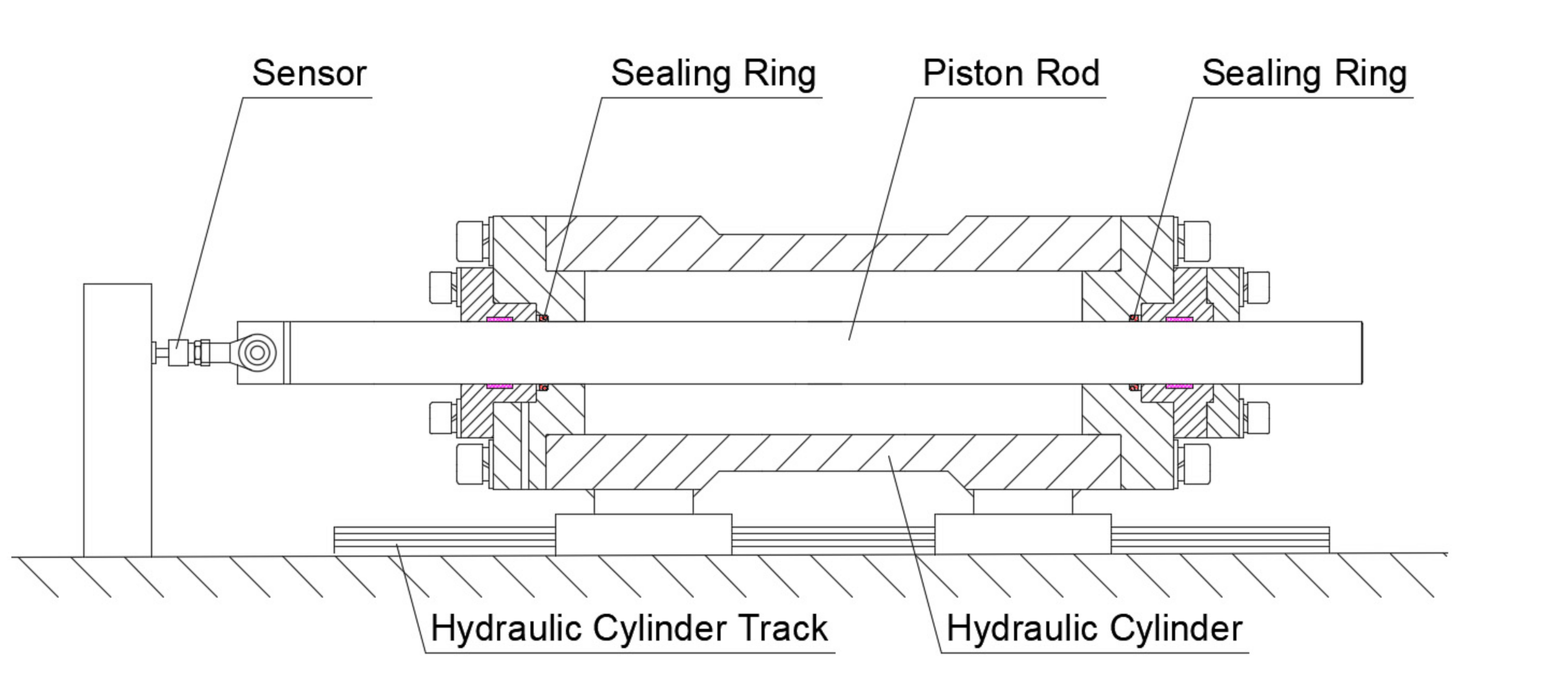
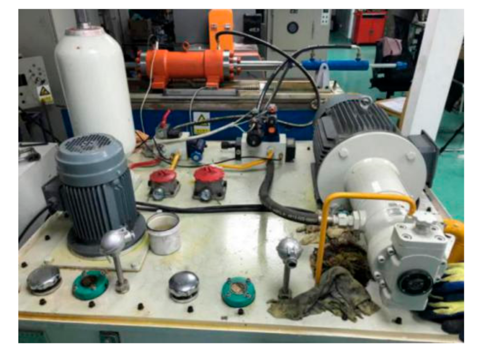
2.2. Experiment of Reciprocating Sealing
2.3. Interface Measurement Methods of Sealing Lips
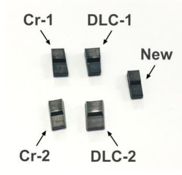
2.3.1. Experimental Samples
2.3.2. Determination of Surface Morphology of Sealing Lip
2.3.3. Determination of Surface Wear of Seal Lip
2.3.4. Determination of Wear Surface Elements of Sealing Lips
3. Results and Discussion
3.1. Reciprocating Sealing Experimental Data Processing and Analysis
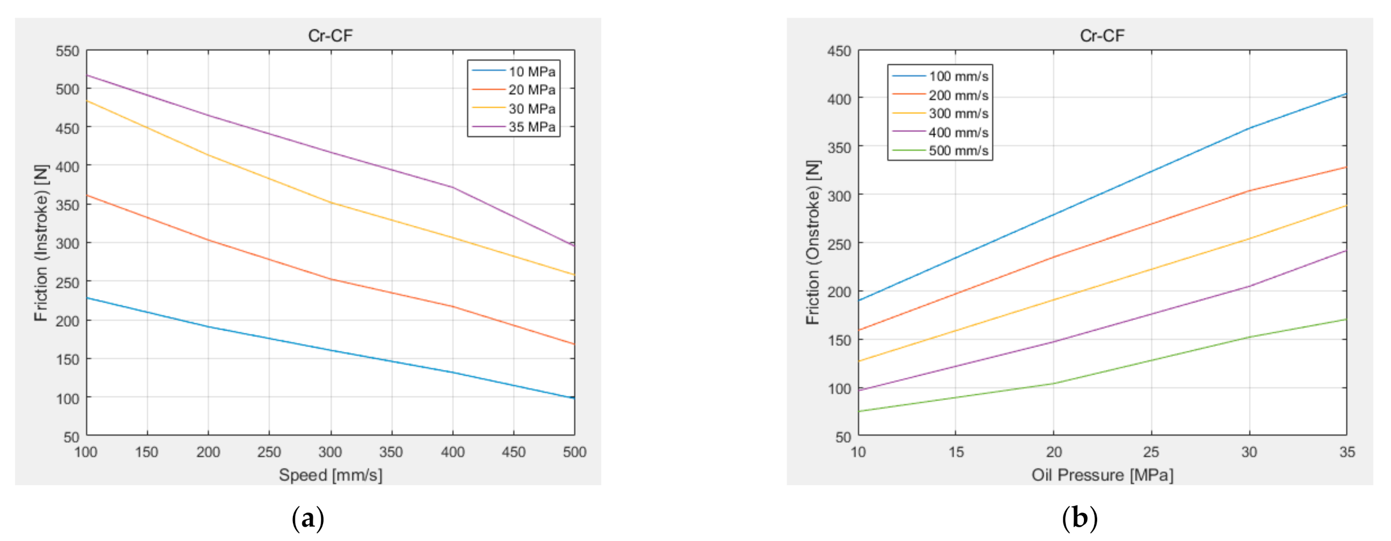
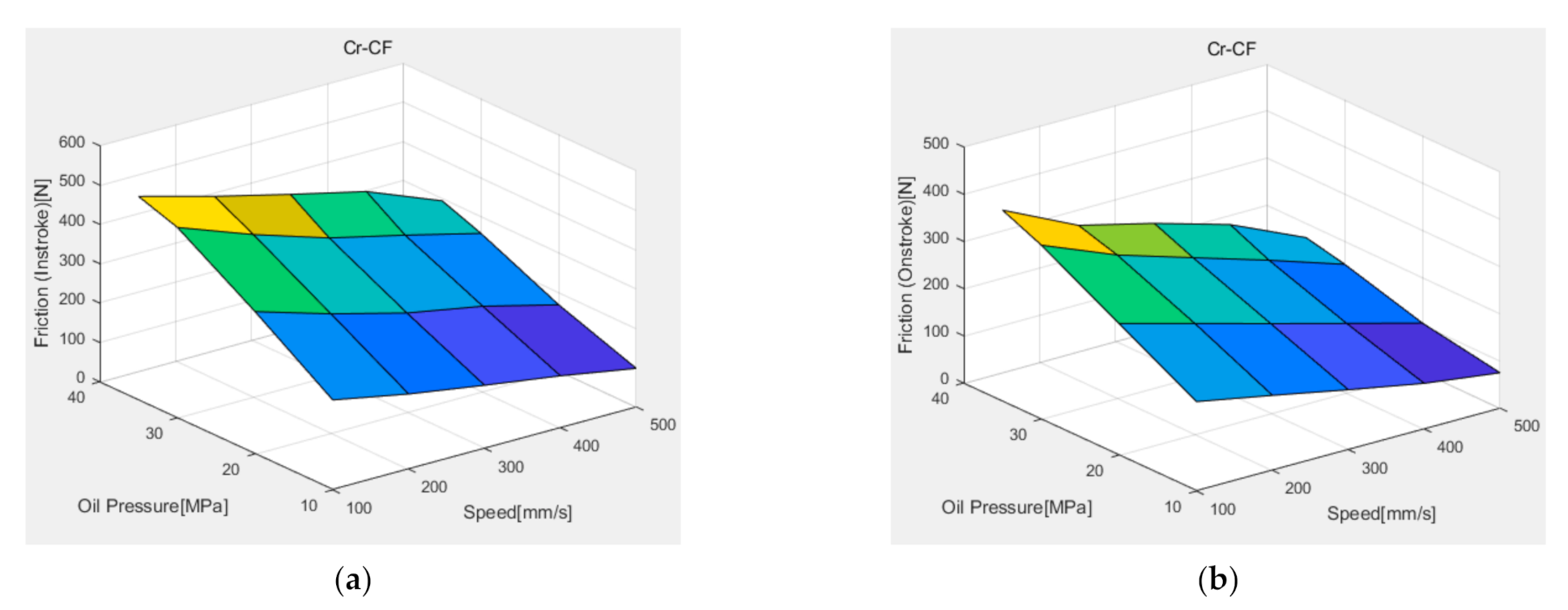
3.1.1. Analysis of Friction between Seal Ring and Chrome-coated Piston Rod
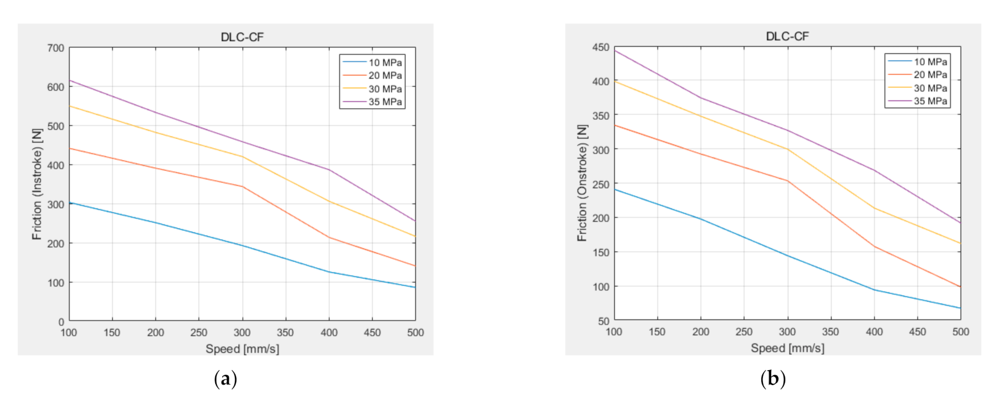
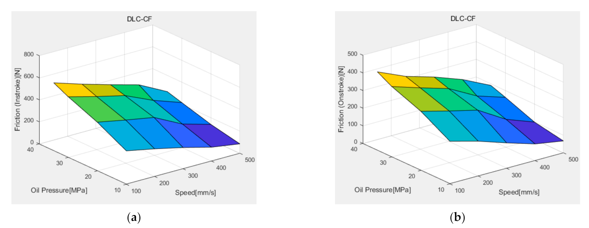
3.1.2. Analysis of Friction between Seal Ring and DLC-coated Piston Rod
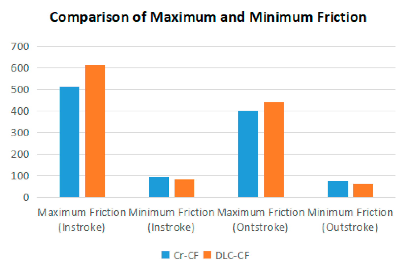
3.1.3. Comparison of Friction between Piston Rods of Different Coating Materials
3.2. Sealing Lip Interface Performance Analysis
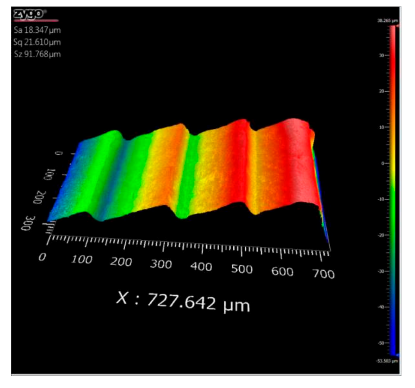
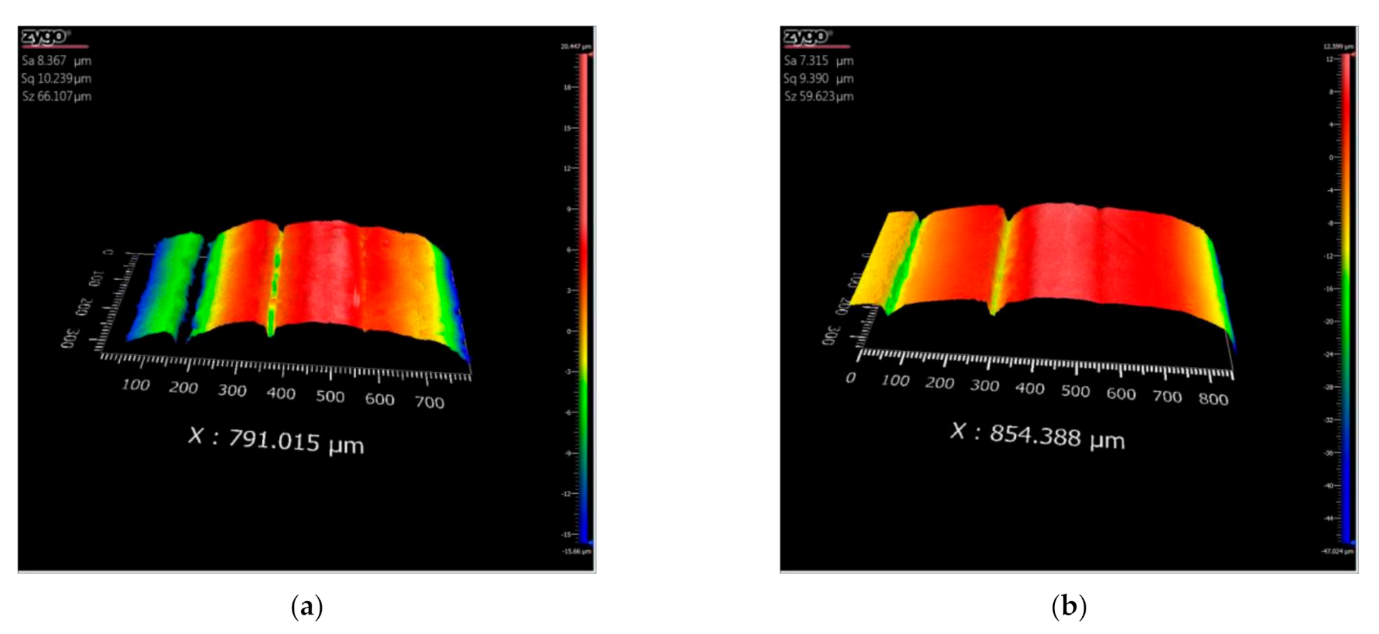
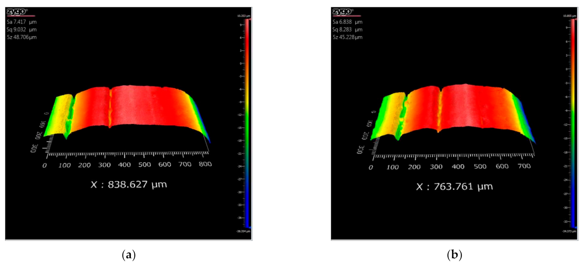
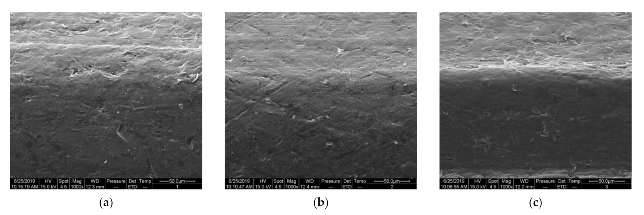
3.2.1. The Surface Morphology of Sealing Lips
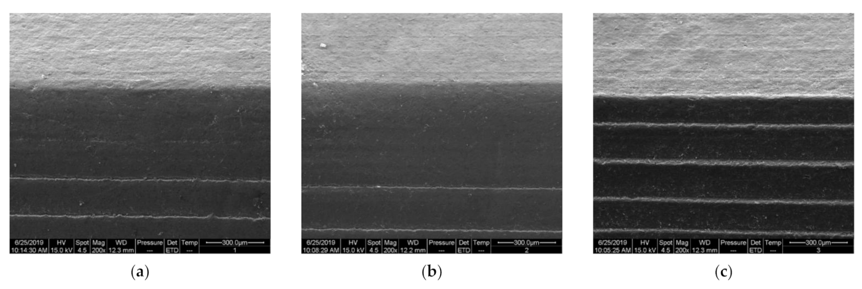
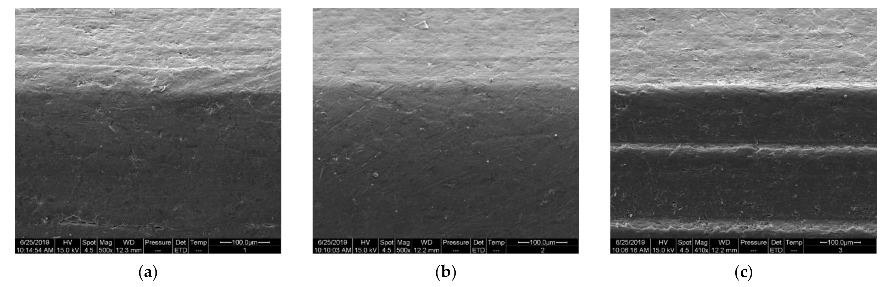
3.2.2. Surface Wear of Seal Lips
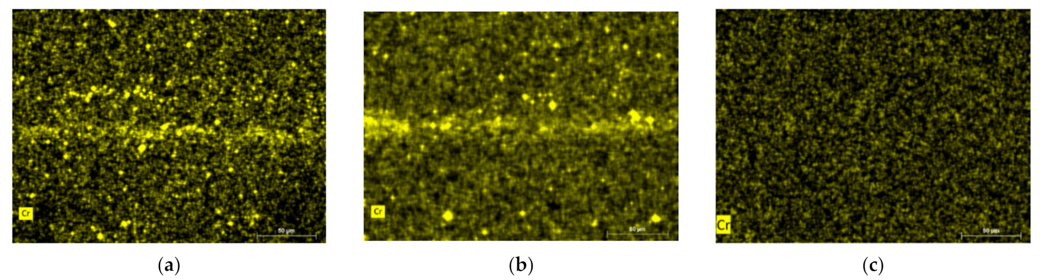
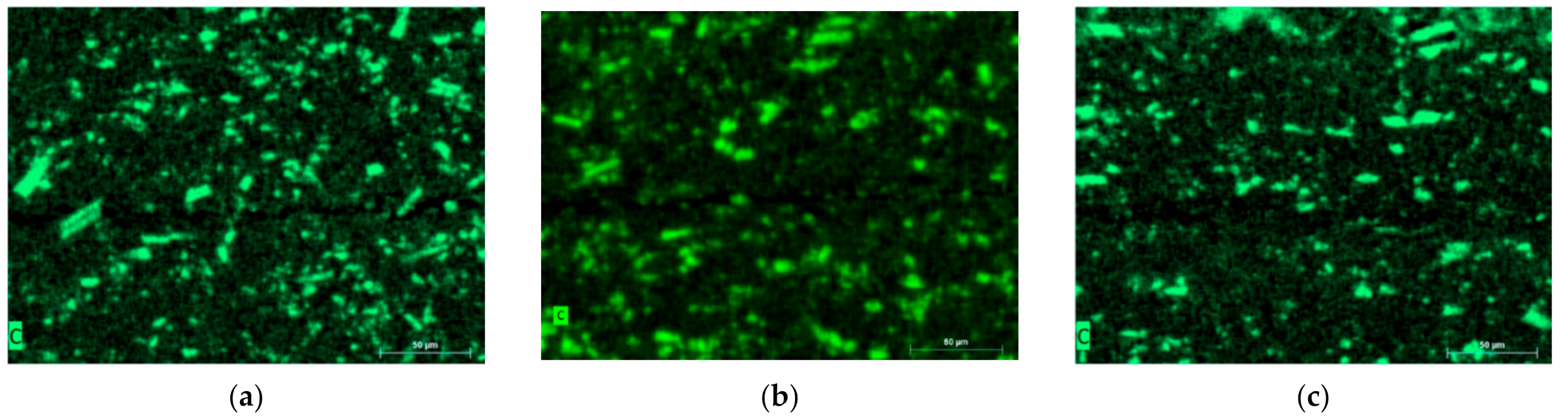
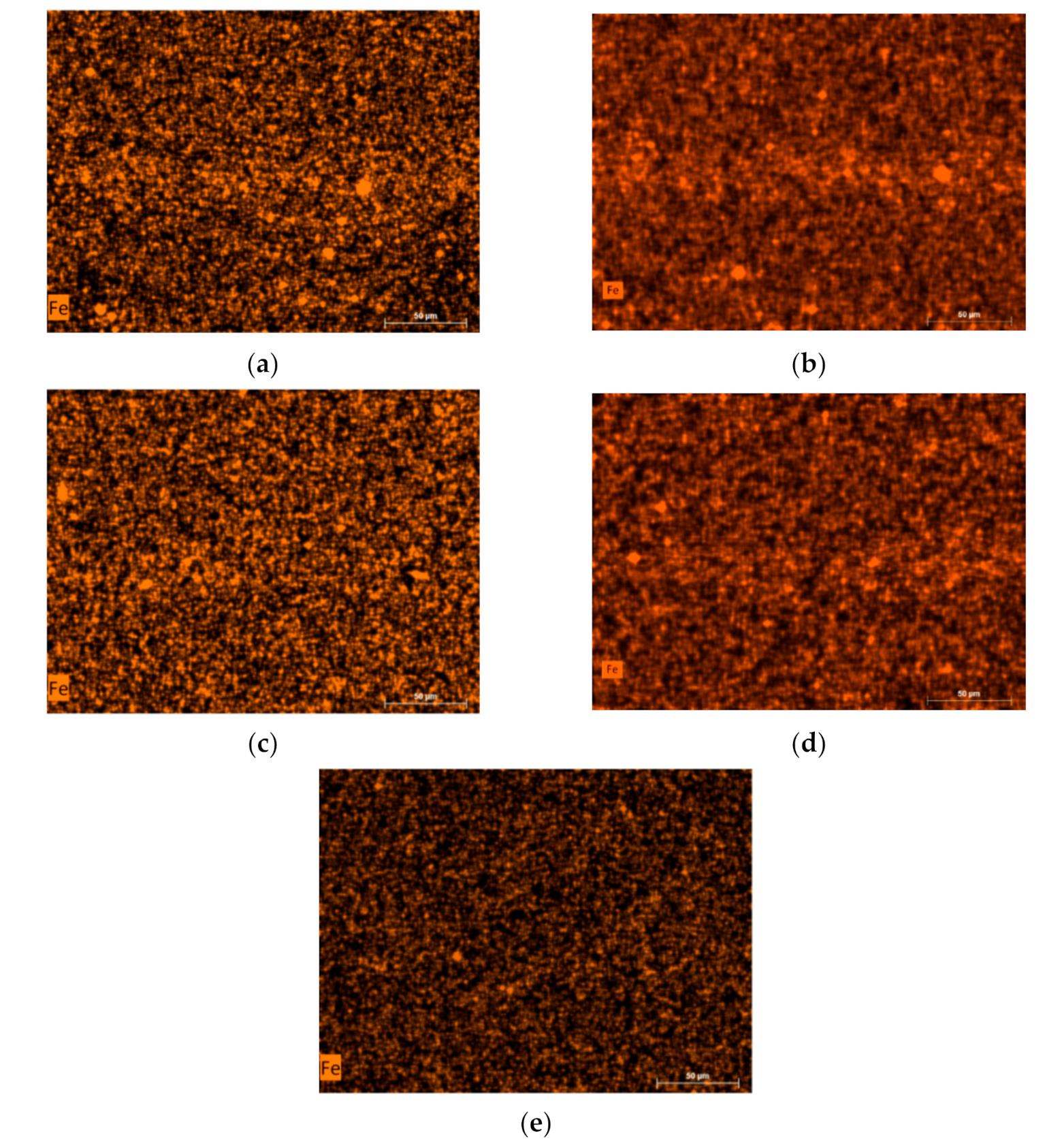
3.2.3. Wear Surface Elements of Sealing Lips
3.3. Sealing Ring and Piston Rod Processing Recommendations
4. Conclusions
- (1)
- DLC (diamond-like) material is hard. In the white light interference experiment, the lip of the seal ring which is in contact with the DLC-coated piston rod is obviously worn, and the wear amount is large. In the cold field emission electron microscopy experiment, the element content of the sealing ring contact area C in contact with the DLC-coated piston rod is increased. The Cr material is soft. In the white light interference experiment, the lip of the seal ring which is in contact with the Cr-coated piston rod is not obvious, and the wear amount is small. In the cold field electron microscopy experiment, the content of Cr in the contact area of the sealing ring in contact with the Cr-plated piston rod is significantly increased. In summary, DLC-coated materials are better.
- (2)
- Since the coating layer of the piston rod is detached, abrasive grains are generated, and the abrasive grains cause the seal ring to be worn and form a wear scar. The coating of the Cr-coated piston rod and the DLC-coated rod have different degrees of damage, and the material transfer of the stainless steel piston rod metal causes an increase in the Fe element content of the two used seals. Although the sealing ring PTFE material is softer than the two coating materials, element transfer occurs with the dual material after the contact motion.
- (3)
- The friction and wear of the piston rod on the piston rod can be reduced by increasing the precision of the turning machine and reducing the height difference between the two turning marks. At the same time, the coating material should be reinforced before the piston rod is coated to prevent the coating material from falling off and destroying the sealing ring.
Author Contributions
Funding
Institutional Review Board Statement
Informed Consent Statement
Data Availability Statement
Conflicts of Interest
References
- Craggs, A. The transient response of a couple plate-acoustic system using plate and acoustic finite elements. J. Sound Vib. 1971, 4, 509–528. [Google Scholar] [CrossRef]
- Suzuki, S. Boundary element analysis of cavity noise problems with complicated boundary. J. Sound Vib. 1989, 130, 147–153. [Google Scholar] [CrossRef]
- Zhang, M.T.; Suo, S.F.; Jiang, Y.; Meng, G.Y. Experimental Measurement Method for Contact Stress of Elastic Metal Sealing. Metals 2018, 8, 942. [Google Scholar] [CrossRef] [Green Version]
- Zhang, M.; Suo, S.; Guo, F.; Jia, X.; Meng, G. Research of Forward Design Method of Contact Dynamic Seal. IOP Conf. Ser.: Mater. Sci. Eng. 2018, 408, 012012. [Google Scholar]
- Zhang, M.T.; Shi, S.W.; Suo, D.F.; Meng, G. Experimental Study of Friction and Wear Interface Performance of Reciprocating Seal based on Sterling Seal. Chin. Hydraul. Pneum. 2019, 11, 99–104. [Google Scholar]
- Nikas, G.K.; Sayles, R.S. Nonlinear Elasticity of Rectangular Elastomeric Seals and its Effect on Elastohydrodynamic Numerical Analysis. J. Tribol. Int. 2004, 37, 651–660. [Google Scholar] [CrossRef]
- Thatte, A.; Salant, R.F. Transient EHL Analysis of an Elastomeric Hydraulic Seal. J. Tribol. Int. 2009, 42, 1424–1432. [Google Scholar] [CrossRef]
- Weber, D.; Hass, W. Wear Behavior of PTFE Lip Seals with Different Sealing Edge Designs, Experiments and Simulation. J. Seal. Technol. 2007, 2, 7–12. [Google Scholar] [CrossRef]
- Nikas, G.K. Eighty years of research on hydraulic reciprocating seals: Review of tribological studies and related topics since the 1930s. Proc. Inst. Mech. Eng Part J J. Eng. Tribol. 2010, 224, 1–23. [Google Scholar] [CrossRef]
- Crudu, M.; Fatu, A.; Cananau, S.; Hajjam, M.; Pascu, A.; Cristescu, C. A numerical and experimental friction analysis of reciprocating hydraulic ‘U’ rod seals. Proc. Inst. Mech. Eng Part J J. Eng. Tribol. 2012, 226, 785–794. [Google Scholar] [CrossRef]
- Wu, Q.; Suo, S.F.; Liu, X.F.; Huang, W.F.; Wang, Y.M. Static Sealing and Pseudo-sealing Characteristics of Nitrile Rubber O-ring. Lubr. Eng. 2012, 11, 21. [Google Scholar]
- Yang, B.; Salant, R.F. Elastohydrodynamic lubrication simulation of O-ring and U-cup hydraulic seals. Proc. Inst. Mech. Eng Part J: J. Eng. Tribol. 2011, 225, 603–610. [Google Scholar] [CrossRef]
- Fatu, A.; Hajjam, M. Numerical modelling of hydraulic seals by inverse lubrication theory. Proc. Inst. Mech. Eng. Part G J. Aerosp. Eng. 2011, 225, 1159–1173. [Google Scholar] [CrossRef]
- Bhaumik, S.; Kumar, S.R.; Kumaraswamy, A. Experimental Investigation and FE Modelling of Contact Mechanics Phenomenon in Reciprocating Hydraulic U-Seals for Defence Applications. Appl. Mech. Mater. 2014, 592–594, 1950–1954. [Google Scholar] [CrossRef]
- Huang, L. Simulation Research on Performance of Reciprocating Seal Used in Stamping Equipment; Tsinghua University: Beijing, China, 2015. [Google Scholar]
- Huang, L.; Jia, X.H.; Guo, F. Optimization Design of Y-Sealing Ring Based on Finite Element Analysis. Lubr. Eng. 2014, 39, 83–88. [Google Scholar]
- Jia, X.H.; Guo, F.; Huang, L.; Wang, L.; Gao, Z.; Wang, Y. Effects of the radial force on the static contact properties and sealing performance of a radial lip seal. Sci. China Technol. Sci. 2014, 57, 1175–1182. [Google Scholar] [CrossRef]
- Dilixiati, A. Reliability Modeling and Experimental Research of Pneumatic Y Seal; Tsinghua University: Beijing, China, 2015. [Google Scholar]
- Dilixiati, A.; Suo, S.F.; Huang, L. Finite Element Analysis on Reliability and Sensitivity of Y-Seal. Lubr. Eng. 2015, 4, 5–10. [Google Scholar]
- Li, Q.; Wang, D.; Zhang, W. Static Sealing Performance and Reliability Finite Element Analysis for Air Hydraulic Actuator O-ring. J. Chin. Hydraul. Pneum. 2018, 4, 69–73. [Google Scholar]
- Guo, F. Research on Dynamic Evolution Rule of Rotary Lip Seals’ Performance Based on Aging and Wear. Ph.D. Thesis, Tsinghua University, Beijing, China, 2014. [Google Scholar]
- Guo, F.; Jia, X.H.; Huang, L.; Wang, Y.M. A Mixed Lubrication Theoretical Model and Experimental Verification of Rotary Lip Seals. J. Mech. Eng. 2014, 50, 137–144. [Google Scholar] [CrossRef]
- Chang, K. Wear Simulation Method of O-ring Based on ANSYS. J. Chin. Hydraul. Pneum. 2018, 2, 98–103. [Google Scholar]
- Ye, S.J. The Friction and wear Properties of The PTFE composites for Seal. In Proceedings of the National Youth Tribology and Surface Engineering Conference, Beijing, China, 22–24 May 2011. [Google Scholar]
- Zheng, X.P.; Shen, X.M.; Li, G.; Peng, X.D. Friction and Wear Characteristics of Acrylonitrile-butadiene Rubber Under Hard Particles Condition. J. Mater. Eng. 2015, 43, 79. [Google Scholar]
- Wu, C.G. Research on Maining Sealing Performance of High Pressure Aircraft Actuator. Master’s Thesis, Tsinghua University, Beijing, China, 2016. [Google Scholar]
- Zhang, F.Y.; Zhao, L.; Li, J.B. Effect of Surface Roughness on Dynamic Sealing Performance of Rectangular Elastomeric Seals. Lubr. Eng. 2015, 40, 30–33. [Google Scholar]
- Zhu, J. Research of the Hydrodynamic Sealing Mechanism and Experiment of Variable Cross Section Sealing Ring. Ph.D. Thesis, Northeast Petroleum University, Daqing, China, 2017. [Google Scholar]
- Yang, F. Research on Friction and Wear Performance of NBR as the Stator of Progressing Cavity Pump. Ph.D. Thesis, Shenyang University of Technology, Shenyang, China, 2014. [Google Scholar]
- Li, X.; Suo, S.; Guo, F.; Wu, C.; Jia, X. A study of reciprocating seals with a new mixed-lubrication model based on inverse lubrication theory. Lubr. Sci. 2018, 30, 126–136. [Google Scholar] [CrossRef]
- Wen, S.Z.; Huang, P. Principles of Tribology; Tsinghua University Press: Beijing, China, 2018. [Google Scholar]


| Rod Diameter df8/h9 | Bottom Diameter D1 H9 | Groove Width L + 0.2 | Mounting Chamfer L | Fillet r | S max | ||
|---|---|---|---|---|---|---|---|
| 10 Mpa | 20 Mpa | 40 Mpa | |||||
| 50 | 50 + 15.0 | 7.5 | 5.0 | 0.3 | 0.50 | 0.40 | 0.30 |
| Item | Index | |
|---|---|---|
| Appearance | Red transparent liquid | |
| Kinematic Viscosity (mm2/s) | 100 °C | 5.306 |
| 40 °C | 13.84 | |
| −40 °C | 383.2 | |
| −54 °C | 1456 | |
| Flash Point (°C) | 104 | |
| Condensation Point (°C) | −74 | |
| Density (20 °C) (kg/m3) | 839.3 | |
| Contact with Cr-Coated Piston Rod | Contact with DLC-Coated Piston Rod | |
|---|---|---|
| First Experiment | Cr-1 | DLC-1 |
| Second Experiment | Cr-2 | DLC-2 |
| New Seal | New | |
| Samples | Sa | Sq | Sz | |
|---|---|---|---|---|
| New | 18.347 | 21.610 | 91.968 | |
| Cr | Cr-1 | 8.367 | 10.239 | 66.107 |
| Cr-2 | 7.417 | 9.032 | 48.706 | |
| DLC | DLC-1 | 7.315 | 9.390 | 59.623 |
| DLC-2 | 6.838 | 8.283 | 45.228 | |
Publisher’s Note: MDPI stays neutral with regard to jurisdictional claims in published maps and institutional affiliations. |
© 2021 by the authors. Licensee MDPI, Basel, Switzerland. This article is an open access article distributed under the terms and conditions of the Creative Commons Attribution (CC BY) license (http://creativecommons.org/licenses/by/4.0/).
Share and Cite
Zhang, M.; Li, D.; Suo, S.; Shi, J. Piston Rod Coating Material Study of Reciprocating Sealing Experiment Based on Sterling Seal. Appl. Sci. 2021, 11, 1370. https://doi.org/10.3390/app11041370
Zhang M, Li D, Suo S, Shi J. Piston Rod Coating Material Study of Reciprocating Sealing Experiment Based on Sterling Seal. Applied Sciences. 2021; 11(4):1370. https://doi.org/10.3390/app11041370
Chicago/Turabian StyleZhang, Miaotian, Decai Li, Shuangfu Suo, and Jianwen Shi. 2021. "Piston Rod Coating Material Study of Reciprocating Sealing Experiment Based on Sterling Seal" Applied Sciences 11, no. 4: 1370. https://doi.org/10.3390/app11041370