Article

Controllable Height Hopping of a Parallel Legged Robot

1
Intelligent Robotics Institute, School of Mechatronical Engineering, Beijing Institute of Technology, Beijing 100081, China
2
Gradute School of Information Science and Technology, The University of Tokyo, Tokyo 113-8657, Japan
3
The Beijing Advanced Innovation Center for Intelligent Robots and Systems, Beijing Institute of Technology, Beijing 100081, China
4
Department of Mechanical Engineering and Intelligent Systems, The University of Electro Communications, Tokyo 182-8585, Japan
*
Authors to whom correspondence should be addressed.
Appl. Sci. 2021, 11(4), 1421; https://doi.org/10.3390/app11041421
Submission received: 5 January 2021 / Revised: 31 January 2021 / Accepted: 2 February 2021 / Published: 4 February 2021
(This article belongs to the Special Issue Biorobotics and Bionic Systems)

Abstract

:
Legged robots imitating animals have become versatile and applicable in more application scenarios recent years. Most of their functions rely on powerful athletic abilities, which require the robots to have remarkable actuator capacities and controllable dynamic performance. In most experimental demonstrations, continuous hopping at a desired height is a basic required motion for legged robots to verify their athletic ability. However, recent legged robots have limited ability in balance of high torque output and actuator transparency and appropriate structure size at the same time. Therefore, in our research, we developed a parallel robot leg using a brushless direct current motor combined with a harmonic driver, without extra force or torque sensor feedback, which uses virtual model control (VMC) to realize active compliance on the leg, and a whole-leg control system with dynamics modeling and parameter optimization for continuous vertical hopping at a desired height. In our experiments, the robot was able to maintain stability during vertical hopping while following a variable reference height in various ground situations.

1. Introduction

The most prominent advantage of a legged robot is its outstanding ability of highly dynamic locomotion strategies such as running and jumping, imitating real legged animals in field situations [1]. In general, two main elements, actuator output ability and motion controllability, place great demands on the systematic design and control methods of bio-inspired legged robots. To examine these requirements on robot design, continuous height-controlled hopping serves as a fair criterion for practical research because it is a type of simplified movement pattern.
The capacity for explosiveness can be embodied in robot’s maximum jumping height, which is heavily dependent on the actuator output. Most previous bipedal robot such as ASIMO [2] and ATRIAS [3], in order to support heavy trunk and realize accurate position control, using motors with relatively high-ratio reducers, have limited ability in robot jumping and running research because of the non-transparency in reducers. In other words, the reason for the weakness in dynamic motion is that the large reducer ratio brings increased friction and other nonlinear elements to the actuator. On the other side, most low-ratio or even direct-driven actuators can accurately control their output with high transparency, but they have limited output torque which can only be used in small-sized robot. To overcome this conflict, MIT Cheetah series robot [4,5,6,7] used a high-torque-density brushless direct current (BLDC) motor with a large gap radius as its actuator [8,9]. This type of actuator is typically a large-torque, low-speed motor that usually cooperates with a low-ratio gearbox to achieve high back-drivability. Nevertheless, this actuator is relatively large in size and heavy when used on robot systems with more degrees of freedom (DoFs), such as humanoid robots. Thus, the balance of output ability, transparency, and structure size for a legged robot is still a crucial problem to be solved.
In terms of hopping height control, Raibert firstly realized controllable hopping of legged robot in 1986 [10]. Later, based on the measurement of real legged animal motion, the spring loaded inverted pendulum (SLIP) model [11] was constructed and became the universal model to describe dynamic motion such as hopping, running, and other manipulations [12]. However, because of the nonlinear characteristics of SLIP model, it is difficult to resolve its dynamics analytically for every step. To address this problem, some approximation methods were proposed, such as the research of Geyer, who assumed a small angular sweep and spring compression [13]. Without SLIP, several other intuitive approaches to hopping height control are available. The simplest approach is to maintain a constant value, such as the actuator input voltage [14] and trunk velocity [15], and further use basic model to realize adaptive hopping control [16]. This type of control is not connected closely to dynamic model, although applicable and universal for most legged robots, lacking control accuracy and maneuverability for a specific robot system. For whole-body jumping control, there are other methods such as ZMP to realize hopping on legged robot [17,18,19]. Besides, virtual model control (VMC) is an efficient method in robot leg or arm control, which has also been validated in walking and jumping motion control [20,21,22]. Nevertheless, with different control target and robot structure, it should be combined with specific superior control strategy.
To balance the requirements of both load supporting ability and dynamic locomotion function, an integrated legged robot system including hardware design and control strategy is plainly needed. In previous work [23], we proposed a parallel-elastic legged robot for loaded jumping. In this paper, focusing on controllable vertical hopping, we describe the development of the parallel legged robot with a high-performance actuator, and use current–torque control on the actuator to implement VMC on the leg; this approach does not require an extra torque sensor but can provide active compliance in jumping and landing. Next, an ideal dynamic model was constructed and the fitting relationship between the virtual model setting and the actual hopping height was generalized. Finally, the control parameter was optimized in simulation and hopping height control was realized based on the proposed model. The main contributions of this paper are:
(1)
To balance requirements of high output, transparency and applicable size of legged robot for vertical hopping motion, a design of integral legged robot system was developed. The actuator used BLDC-harmonic actuator and the main structure is parallel mechanism, which are relatively more suitable for legged robot to perform greater height hopping.
(2)
To realize controllable height hopping, a novel height control strategy combined with VMC, using dynamics model construction and function parameter fitting, was proposed, which is appropriate for our mechanical design and can also meet the requirement without extra sensor measurement and online calculation.
The remainder of this paper is organized as follows. Section 2 introduces the design concept and the details of the robot. Section 3 establishes the dynamic model of the robot system. Section 4 describes the methods for VMC and hopping height control. Section 5 presents the simulation and experimental results. Finally, Section 6 draws conclusions about the consequences of our research and discusses future planning.

2. Robotic System Design

This section depicts the design thought of the actuation, mechanism and control hardware system. The robot prototype is shown in Figure 1a. As in the figure, the robot was limited in vertical slide guides to realize vertical hopping, and a laser range finder was fixed on the top of the guides to measure the height of robot trunk.
The two main requirements in actuator design are high output torque density and high transmission transparency. As introduced in Section 1, the actuator design schemes involving hydraulic and direct-drive motors both have weaknesses. Therefore, scheme of BLDC motor and reducer with appropriate ratio is an optimal approach. In the reducer selection, in contrast to both planetary and cycloidal gear reducers, the harmonic reducer has a lower weight while providing the same ratio. In terms of the actuator feedback system, two main methods are used to realize high-performance torque control on legged robots: torque sensor feedback and motor current feedback control. However, torque feedback such as SEA (series elastic actuator), which is used in many legged robot [24,25], requires an extra elastic feedback unit that has a non-negligible mass and causes unavoidable vibration. Thus, we used motor current feedback as proprioceptive control in our design. In terms of our development target, the main aim of our actuation design is to realize output torque control directly with motor current feedback. Through numerical simulation, we found that a 5.5 kg robot jumping to 1.5 m height with a constant vertical acceleration needs maximum torque about 95 Nm and maximum rotational speed about 100 rpm (joint speed). According to such requirements, we selected a self-developed BLDC motor and a harmonic reducer with a ratio of 1:31 as our actuator. The actuator structure is shown in Figure 1b. Based on this design, the maximum output torque of the actuator can reach 124 Nm theoretically, maximal rotational speed over 4000 rpm, and power density 808.82 W/kg, which is sufficient output for robot’s high jumping. Compared with MIT Cheetah’s large-radius actuator, our design has smaller radius and higher torque–radius ratio of the whole module (details in Table 1), which is more compact for multi-joint robot system [8,9]. To validate linearity and transparency of the actuator, a simple test facility was set as shown in Figure 2a. According to the input current–output torque relation in Figure 2b, we can conclude that the actuator has a certain transparency in action, while it is still different from the ideal condition.
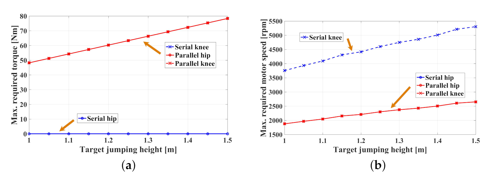
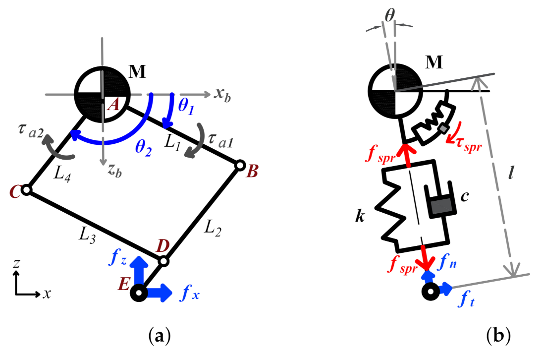
As for structural design, compared with the serial mechanism leg, the parallel leg offers several advantages. First, the knee joint actuator rotates relative to the trunk in the parallel case rather than relative to the thigh, which causes extra inertia for the hip joint. Second, on our robot, as identical thigh and shank lengths were selected for the maximum vertical movement range [23], we found that parallel mechanism has similar torque and speed requirements for the two active joints during the vertical jumping simulation. Thus, we could use two same actuators in active joints. The details of the structure comparison and jumping simulation results are shown in Figure 3 and Figure 4. More comparative analyses of parallel and serial structure of legged robot are presented in another paper [26]. Previous research has shown that the ideal mass ratio of the leg involves a large trunk mass and a lower leg mass [27]. Based on this notion, we used carbon fiber tubes as the leg links and aluminum parts as the joint connections. In our design, the total robot leg mass is 5.2 kg and the motor module weighs 3.04 kg, so the percentage of the total mass taken up by the actuator is approximately 58%. As shown in Figure 5a, the basic robot leg structure is a parallelogram with two DoFs. Compared with serial structure, this configuration contains two parallel joints rotating relative to the trunk base frame. Specifically, we can use two identical actuators on the leg, because of the identical torque and speed requirements as mentioned above.
The control system consists of an industrial personal computer (IPC), the Elmo motor driver and absolute encoder. CAN bus was used as the communication mode between IPC and motor drivers, and control period is 2 ms. Generally, the control system in this paper did not use posture or torque sensors and only used the encoder and current detection.

3. Dynamic Model Analysis

3.1. Actuator Modeling

Inspired by modeling works in [28], based on the complex model, we constructed a simplified one. The ideal output torque of the BLDC motor can be expressed as: T m = C l i m , where i m is the motor winding current and C l is the motor torque coefficient. Therefore, the motor output torque T m can be estimated by current directly. In reducer part of actuation model, inertia of two parts (circular spline and flex spline) in reducer are combined, and elasticity in it is neglected; the complete model is finally simplified as:
T a = 1 N ( C l i m J a θ ¨ m b m θ ˙ m S )
where T a is the actuator output torque, N is the reduction ratio, J a is the sum inertia of the actuator, θ m is the rotation angles of actuator, b m is the viscous coefficient, and S is the static friction term. Obviously, the actuator output torque is related to variables including input current, angular acceleration, angular velocity, and static friction in the current state. In the following section, the actuator model is integrated with the complete structural model for dynamic analysis.

3.2. Leg Structural Modeling

In our design, the basic robot leg mechanism is a parallel four-bar linkage mechanism articulated on the robot’s trunk, with two DoFs gathered on one joint. Compared with the considerable mass and internal damping of actuation module, the mass of link is relatively small to be regarded as linear to the joint space, which simplified the calculation at the same time. Therefore, in the ideal model shown in Figure 5a, the total leg mass is lumped at point A, and the massless sticks L 1 L 4 form the parallel mechanism ( L 1 = L 2 = L 3 = 0.35 m, L 4 = 0.285 m). Given the two joint angles θ 1 and θ 2 , the forward kinematics of the toe position can be derived. Then, the Jacobian matrix J for the leg mechanism can also be solved. Because the linkage mass is calculated on joint space, the foot produced force (e.g., the ground reaction force (GRF)) can be controlled via the joint output torque and expressed directly.

3.3. Integrated Dynamic Modeling

In integrated dynamic model, we limited the planar robot movement in one-dimensional constraint. Based on the model shown in Figure 5a, we introduced the actuator model into the robot structure. In stance phase, the foot mass point is fixed on the floor, so the GRF can act on the CoM (center of mass) directly. Additionally, the horizontal ground force f x is ignored in the following analysis (i.e., set f x = 0). Therefore, the force–torque equation can be rewritten as:
0 f z = J T τ a 1 τ a 2
where f z is vertical ground force, J is Jacobian matrix, and τ a i is T a in (1), which can be represented in vector form as:
τ a = C i m + I θ ¨ + B θ ˙ + f S
where C l , I , and B are the corresponding coefficients in (1) and f S is the static frictional term relative to the force condition. Therefore, we set up a new variable, to represent the sum of two terms in (3):
τ S = C i m + f S
where the variable τ S describes the actuator’s output torque in a static situation. We consider this linear variable to motor current as an integral part in the following analysis, and, as shown in Section 5, it can be calibrated experimentally.
Next, the robot movement is analyzed based on the global coordinates ( x , z ) in Figure 5a. To describe the integrated model, we set a generalized coordinates of robot as: q = [ θ 1 , θ 2 ] T . In the stance phase, the entire robot is assumed to be fixed on the floor. We then use a dynamic equation with the following general expression:
d d t L q ˙ L q + Δ q ˙ = q ˙
f where L is the Lagrange function, Δ is Rayleigh’s dissipation function, and Π is the virtual power of the system. In detail, the Lagrange function is expressed as:
L = T U = 1 2 M z ˙ 2 + 1 2 I 1 θ ˙ 1 2 + 1 2 I 2 θ ˙ 2 2 M g z
where M is the total mass of the robot, I i is the actuation module inertia (including equivalent link inertia), and z is the vertical position of the CoM. Rayleigh’s dissipation function is Δ = 1 2 B 1 θ ˙ 1 2 + 1 2 B 2 θ ˙ 2 2 and the virtual power of the system is Π = θ ˙ 1 τ S 1 + θ ˙ 2 τ S 2 .
Because in our experiment the robot only moves in the vertical direction, several constraints are given as:
P ( q ) + 0 z = 0 , J q ˙ + 0 z ˙ = 0
where P is the position of robot foot calculated by forward kinematics. Hence, the generalized coordinate q can be simplified as a unidimensional coordinate. Specifically, in our robot model, while assuming that L 1 = L 2 , we can transform the constraint equations as follows: θ 1 + θ 2 = π and θ ˙ 1 = θ ˙ 2 , with force constraints τ S 1 = τ S 2 . Therefore, the relationship between the Cartesian coordinate z and joint angle θ 1 can be deduced. Then, Equations (6) and (7) are substituted into (5), and we can ignore the joint inertia I i because I i M numerically. Then, the complete dynamic equation is simplified as:
M z ¨ + B e q z ˙ + M g = f u
where B e q = B 1 + B 2 4 L 1 2 cos 2 θ 1 = B 4 L 1 2 z 2 and f u is the ideal output force on the toe in the vertical direction, which is transformed from the motor torque τ S .
Accordingly, in the stance phase, the entire dynamic model is a nonlinear second-order system with configuration-related parameters. When compared with the ideal spring–mass model, this robot system has variable equivalent inertia and a variable damper coefficient, which are determined by the robot’s posture.
On the other side, in the flight phase, the robot has no contact with the floor. Because the leg was controlled with an extra damping effect in the air, the flight process was a relatively static situation with no leg movement. The flight process is considered only to be affected by gravity and friction on guide rail, which represents a linear process in modeling, while the guide rail friction is regarded as a positive constant f g in this research. In vertical movement, the friction and gravity effects can be combined as a sum of force. Therefore, we set a new acceleration g to substitute for g in the takeoff and upward flight phases, as shown in (9).
g = M g + f g M
In the following modeling calculations, we use g to represent the combined effects of the vertical friction and gravity. The actual value g was calculated in the experiment introduced in Section 5.
According to the modeling above, the foot’s mass is neglected in the dynamic analysis. However, at the critical moment of touchdown and takeoff, the dynamic situation is related to the foot mass. We found that the impact between foot and floor occurred in a very short time period, thus the impact process can be considered as a completely inelastic collision. At takeoff moment, the kinetic energy changes over a very short period. As the result for one hopping period, the energy conservative relationship can be expressed as:
1 2 M z ˙ L O 2 = ( M + m ) g h s m t
where z ˙ L O is the instantaneous velocity immediately before takeoff, m is the foot mass, and h s m t is the summit height during the jump.

4. Control Strategy

4.1. Virtual Model Controller

VMC is a direct but efficient control method that gives the robot some desired dynamic performances similar to a realistic physical system. In whole leg control, VMC provides an intuitive approach that uses the joint torque to imitate virtual component effects such as springs and dampers, and there are many instances in bipedal walking. In our controller, the robot leg is controlled as an ideal mass–spring–damper model, while, in experimental performance, the leg moved under the combined effect of the ideal input and the actual physical configuration.
Figure 5a shows the simplified leg model with one mass point and a massless link mechanism based on Cartesian coordinates, while Figure 5b shows the corresponding virtual model with a spring–damper system based on a polar system. The normal effect of the linear spring system is used to control the leg length l, while the tangential effect of the torsional spring system is used to maintain the leg angle θ at a target value. In the model in Figure 5b, according to the definition of VMC, the virtual force can be written as:
f s p r = k v l ( l o r i l ) c v l l ˙ τ s p r = k v t ( θ o r i θ ) c v t θ ˙
where k v l is the virtual linear spring stiffness and c v l is the virtual damping coefficient; k v t and c v t are the corresponding terms for the virtual torsional spring; l and l o r i are the actual and desired leg lengths (distance from point A to E in Figure 5a), respectively; and θ and θ o r i are the actual and desired leg angles (angle θ in Figure 5b), respectively.
After that, the desired virtual force and torque are transformed into the corresponding foot produced force in Cartesian coordinates as f x and f z , which can be used to calculate the joint torque required to generate this foot force. Ultimately, because the internal modeling effect in dynamic motion is far less than the torque output, we consider to directly control τ S in the VMC closed loop, and regard the rest of the robot system as a whole dynamics model for height control, in which the specific parameters can be estimated through simulation and experiment. Therefore, we assigned the calculated target torque to τ S as the input. The control law can then be written as:
τ S = J P T f s p r = J P T ( K v · Δ p C v · P ˙ )
where J P is the Jacobian matrix between the joint torque and the foot force in polar coordinates; p = [ l , θ ] T ; and f s p r , K v and C v are the corresponding vectors or matrices in (11). In general, we can control the desired dynamic characteristics of the robot leg by varying the given virtual model parameters and implement the virtual force by producing the desired motor torque.

4.2. State Machine Design and Height Measurement

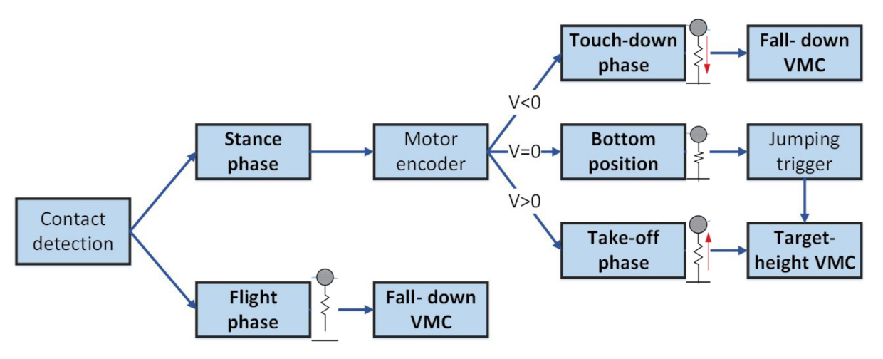
Each hopping motion period can be divided into three sections with different movement situations. In experiments, we used only the encoder and the current sensor to measure the leg’s posture parameters and estimate the robot’s state. Figure 6 shows a schematic of the hopping control architecture in three states of one hopping period. In the figure, contact detection was implemented via the toe’s position variation, which is deduced from the joint angle. When the leg length is compressed to a specified value, the robot can be considered to have reached the stance phase. The bottom position detection is according to toe’s vertical velocity (which has the same absolute value with CoM velocity). When the absolute value of toe velocity is less than a threshold (e.g., 0.01 m/s) for a certain time, the robot could be considered as reaching the bottom position.
For height measurement in each jump, we used time difference in the flight phase to deduce the actually reached summit height. In the experiments, we measured Δ T between adjacent takeoff and touchdown moments, and then used Equation (13), deduced from basic distance calculation formula, to compute the summit height.
h s m t = 1 2 g · Δ T 2 Δ h L T g Δ T 2
where Δ h L T is the height difference between the takeoff and touchdown moments, which can be calculated through input virtual coefficient.

4.3. Height Control Strategy

An ideal spring–mass model can realize continuous hopping directly without energy consumption. However, as mentioned above, our robot leg with its internal damping does not have this capacity without extra energy input. In this case, we used different desired parameters in VMC at different moments to make the robot hop to a targeted summit height. As shown in Figure 6, our controller includes two VMC modes: fall-down VMC and target-height VMC.
In the flight and touchdown phase, we used the VMC law with a constant virtual stiffness, damping, and initial leg length to maintain the stability and compliance of the robot. The initial kinetic energy and gravitational potential energy were transformed into damping energy consumption during this touchdown process. However, this process in experimental situation is not linear as it is in simulation-based calculations. Some tiny chattering will occur during this impact process that may even cause vibration in the velocity in the following movement. Therefore, we left out the analysis of the detailed touchdown procedure at this stage and only measured the height at the bottom position h B as the prior value for subsequent control.
After the bottom position, the robot enters the takeoff phase. In this phase, we changed VMC into target-height module. Specifically, we proposed a height mapping function based on the modeling in Section 3 and parameter calibration in following simulation and experiment. The prospective hopping height of the next jump can be expressed as:
h ^ s m t = f ( h B , k v l )
where h ^ s m t is the estimated hopping height in the next period, a nonlinear function of the bottom height h B in the previous period and the desired virtual stiffness k v l for the next takeoff motion. If the reduction ratio is small enough to enable linear representation of the system, the differential equation for the dynamics may be solved and f could thus be expressed analytically. However, because of the complexity of the model in (8), it is difficult to obtain an analytical solution for this mapping relation. To avoid this difficulty, we used simulations with approximate parameters to calculate numerical solutions and fitted this binary function in a mathematic model. The results of the simulation and fitting processes are shown in Section 5. After using mathematical model to fit function f as in (15) and deducing its analytical solution in (16), we can use the given values bottom height h B and target summit height h d as arguments to calculate the required stiffness k v l in the controller.
h ^ s m t = f ( h B , k v l ) = p 0 + p 1 k v l + p 2 h B + p 3 k v l 2 + . . . + ϵ
k v l = S ( h d , h B )
where p 0 p 5 are fitting coefficients, ϵ is a high-order infinitesimal, S is the solution of function f , and h d is the desired hopping height in the next period. Thus, we get the control law of desired summit height according to (14).

5. Simulation and Experiment

5.1. Simulation and Results

The main goal of the simulations was to find a numerical fitting solution for function f , while we were not clear about its specific analytical form before experiment. Firstly, we performed preliminary experiments to calibrate the basic system parameters, e.g., static friction in the actuator and constant friction f g on the guide rail. In the calibration, we used simple facility to fitted approximate linear relation of the motor current and output torque, as in Figure 2b, to solve for the friction f S in (4). We could then control τ S directly, as introduced previously. In the next calibration, according to the illustration in Section 3.3, we designed a free falling experiment to estimate the friction f g of the guide rail. In the results, the equivalent acceleration on the rail is approximately 11 m/s 2 .
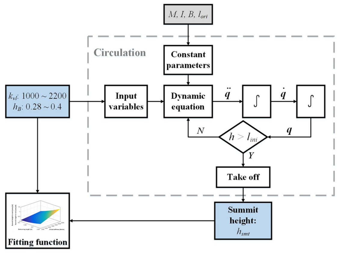
In simulation, we constructed a mathematical dynamic model as described in Section 3 and used M a t l a b to implement the numerical calculations. Each simulated period only consists of the takeoff phase from the bottom position until the takeoff moment, and the final objective is to find the function f introduced in Section 4.3. One round of simulation framework is shown in Figure 7, and the specific simulation parameters are according to actual robot prototype. Based on this framework, ranges of virtual stiffness k v l and initial bottom height h B values were input to the model for circulation and the corresponding summit hopping heights were obtained. After many simulations (about 5000), series of input and output values were collected, and we used the fitting method to get approximation function f . We found that the fitting relation for k v l , h B , and h s m t (function value of f ) can be approximately expressed as a quadratic polynomial, as follows:
h s m t ( i ) = p 0 + p 1 k i + p 2 h B ( i ) + p 3 k i 2 + p 4 k i h B ( i ) + p 5 h B ( i ) 2 + ϵ i
where h s m t ( i ) , k i , and h B ( i ) are h s m t , k v l , and h B in ith simulation, respectively. Then, we could use the optimization function in (18) to find the appropriate parameter value p 0 to p 5 .
min ( f ( h B ( i ) , k i ) ( p 0 + p 1 k i + p 2 h B ( i ) + p 3 k i 2 + p 4 k i h B ( i ) + p 5 h B ( i ) 2 ) ) 2 = ϵ i 2
Finally, p 0 - p 5 were optimized as 0.426, 0.00156, −5.341, 2.2 × 10 8 (negligible in actual control calculation), −0.00356, and 10.68, respectively. From the fitting function, R-square is 0.9997, which basically satisfied our needs.

5.2. Single Landing-Jumping Experiment

The fundamental purpose of this section is to verify the experimental effects of the actuator mechanism and the VMC method and to gather actual data during hopping to rectify the control function. According to VMC as (12), the leg performed as a virtual polar-coordinate spring–damper system. An external force acting on the foot end can cause it to be displaced; after the force is removed, the leg recovers to its initial posture. The leg generally realized good active compliance on its toe and this played an important role in impact mitigation.
In the landing–jumping experiment, the robot fell to the floor and then rebounded with higher stiffness. As noted above, the leg in the flight phase is controlled using constant stiffness and damping. In this experiment, the stiffness k v l is 1000 N/m, the damping c v l is 30 Ns, and the original length is 0.5 m. In the takeoff phase, k v l is 1700 N/m, c v l is 0, and the original length is 0.6 m. In the experiment, the robot jumped to approximately 0.64 m (from ground to toe).
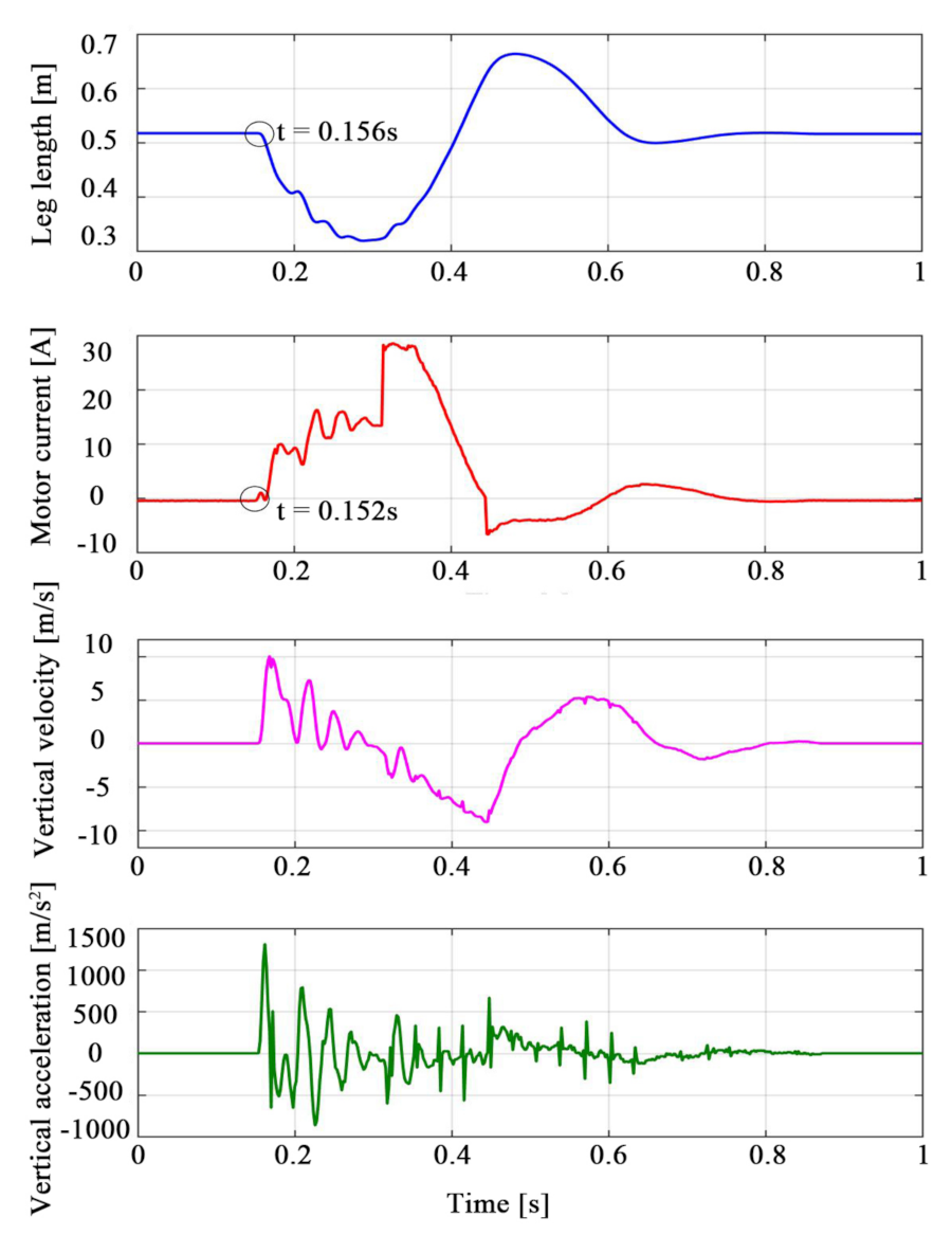
Figure 8 shows the measured data recorded during the experiments. Except for the ground-contact moment, the leg length curve shows ideal continuous and smooth characteristics, thus proving the effectiveness of the VMC method. Circular marks in the figure indicate the sudden changes in the curves. Obviously, current can be used to detect the external impact more quickly. However, the subsequent current curve is not continuous because a little chattering occurs during impact. In the other two graphs, the velocity fluctuates dramatically during the touchdown process but remains relatively smooth during takeoff and flight, while the acceleration is noisier throughout the movement.

5.3. Constant Height Hopping

The aim of the constant-height hopping experiment was to prove the feasibility of the height control method proposed in Section 4.3 and its adaptability to different ground levels.
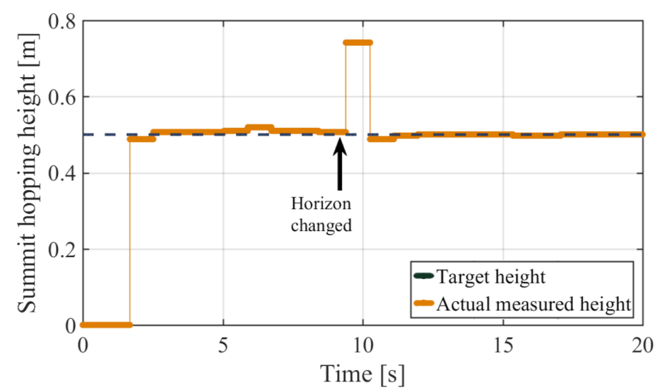
First, the robot leg was controlled using VMC and height control strategy for constant height hopping. Subsequently, we set the robot leg hopping continuously on a stool (stool height: 0.48 m) at a constant height of 0.5 m (relative to the stool). Next, the stool was removed between the toe and the ground. The leg then fell to the ground and maintained its height at 0.5 m relative to the ground. The entire process is shown in photographs in Figure 9, where we see that the leg can maintain a constant height relative to its stance phase, even when the floor height changes. Data records of this process are presented in Figure 10 and Figure 11.
In Figure 10, one short solid line represents the calculated summit height (based on internal sensor data and the identified g’ according to (13), which is also similar to external sensor results but with lower accuracy) of the previous period. Because the calculated value can only be updated after each touchdown, the value at the current time represents the previous period’s summit height. The black arrow labeled “Horizon changed” indicates the moment of stool removal. After this moment, the leg has an unusual height because the flight time was accidentally prolonged. However, the specific value of this height is meaningless because the stool’s height is unknown. In the next period, the robot returned to its target height of 0.5 m. Figure 11 shows that, after the stool was removed, the leg length and the motor current changed dramatically, and the motor produced more power to maintain the virtual model for impact mitigation. The leg then recovered rapidly to its normal situation and still realized height control in subsequent periods, which verified its impact resistance and its adaptability to variable horizon heights. From the motor current curve shown in Figure 11, we found that the current in the touchdown phase fluctuated slightly after the horizon changed. After analysis, we believe that this resulted from the difference in physical stiffness between the stool and the floor. Consequently, the stability and adaptability of the constant height control approach on variable-level terrain was verified.

5.4. Variable Height Hopping

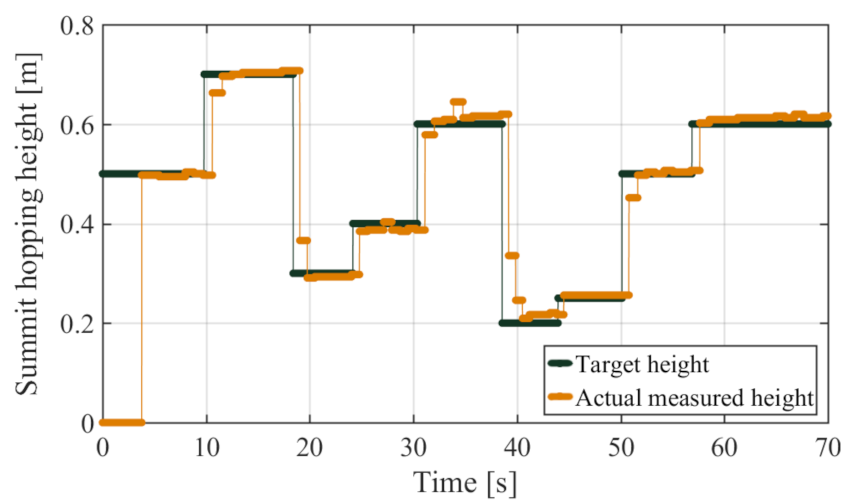
In two-dimensional forward movement of the spring–mass model, the desired hopping height should be a real-time variable that adapts to different situations. Therefore, after constant height control, we focused on continuous variable-height control. During long-term continuous hopping, we changed the target summit height randomly every few hopping periods. Figure 12 shows the different moments when the leg was in each summit position. As shown in Figure 13, depending on the desired value, the actual summit height was adjusted rapidly by the controller, almost within two periods. Both calculated values and physical measurements from the video demonstrated that the real hopping height always remained very close to the desired value. Generally, this experiment verified the feasibility of the height control strategy during continuous variable-height hopping in a limited range.

5.5. Discussion

The experiment results show that the robot leg realized active compliance and controllable height hopping, thus proving ideal robot system performance and its good effect in combination with the height control strategy. First, because the system design used a harmonic driver as the motor reducer in the actuator, the system achieved successful dynamic motion control and impact mitigation during hopping. The results illustrate the mechanical and control feasibility of the low-ratio harmonic reducer during extreme hopping movements. As shown in Figure 8, the leg can touch down in a mitigating way at high initial velocity by relying on the good performance of the actuator and current control via the VMC method. Incidentally, the effect of the leg structure absorbing much of the impact between the actuator and the ground is also beneficial. Although we found in the experiments that the back-drivability of our actuator was not better than that of other direct or quasi-direct drive actuators because of the intrinsic damping between the gears, we could still use model construction to describe these parameters and subsequently implement accurate control.
For hopping height control, we designed a control method based on VMC state switching and control parameter optimization. Because of the difficulty of parameter identification and the computing complexity of accurate modeling during real-time control, we proposed a method that can bypass specific prototype modeling while using fewer identification parameters to achieve the control target. Generally, this approach does not require further feedback sensor data or specific modeling parameter identification. The method uses only takeoff and touchdown detection to estimate the hopping height and controls this value to meet a desired plan, even with variable ground horizon heights. Therefore, it is very useful for practical applications and can be extended in multi-dimensional situations to perform hopping height control or forward running control. Furthermore, we can introduce an online least squares method to this system to rectify its control parameters in real time.

6. Conclusions

This paper introduces a novel parallel legged robot and a corresponding hopping height control approach. The main contributions of this design are as follows. A BLDC motor and harmonic driver are used as an actuator and combined with the VMC method to realize highly dynamic movement during large-height jumping and landing, which proved the feasibility of the harmonic driver in such a severe working environment and raised the possibility of using this actuator design on other legged robots, e.g., humanoid robots. Additionally, a hopping height control method was designed based on dynamic modeling and parameter optimization that controlled the robot’s hopping in desired height and adapted to different horizon situations.
In the future, we intend to expand this method into planar and spatial motion control, e.g., forward hopping and running. Furthermore, this design and corresponding control method can also be used in bipedal and quadruped robots for dynamic locomotions.

Author Contributions

Conceptualization, Z.H., F.M., and X.C.; funding acquisition, X.C., Z.Y., and Q.H.; investigation, X.F.; methodology, Z.H.; software, F.M. and Z.Y.; supervision, A.M. and Q.H.; validation, X.C., Z.Y., and R.S.; and writing—original draft preparation, Z.H. All authors have read and agreed to the published version of the manuscript.

Funding

This work was supported by the National Key Research Program of China (Grant 2017YFE0128300) and the National Natural Science Foundation of China (Grants 91748202 and 61903038).

Institutional Review Board Statement

Not applicable.

Informed Consent Statement

Not applicable.

Conflicts of Interest

The authors declare no conflict of interest.

References

  1. Mo, X.; Ge, W.; Miraglia, M.; Inglese, F.; Zhao, D.; Stefanini, C.; Romano, D. Jumping Locomotion Strategies: From Animals to Bioinspired Robots. Appl. Sci. 2020, 10, 8607. [Google Scholar] [CrossRef]
  2. Sakagami, Y.; Watanabe, R.; Aoyama, C.; Matsunaga, S.; Higaki, N.; Fujimura, K. The intelligent ASIMO: System overview and integration. In Proceedings of the IEEE/RSJ International Conference on Intelligent Robots and Systems, Lausanne, Switzerland, 30 September–4 October 2002; pp. 2478–2483. [Google Scholar]
  3. Hubicki, C.; Grimes, J.; Jones, M.; Renjewski, D.; Sprowitz, A.; Abate, A.; Hurst, J. ATRIAS: Design and validation of a tether-free 3Dcapable spring-mass bipedal robot. Int. J. Robot. Res. 2016, 35, 1497–1521. [Google Scholar] [CrossRef]
  4. Seok, S.; Wang, A.; Chuah, M.; Hyun, D.; Lee, J.; Otten, D.; Lang, J.; Kim, S. Design principles for energy-efficient legged locomotion and implementation on the MIT cheetah robot. IEEE/ASME Trans. Mechatron. 2014, 20, 1117–1129. [Google Scholar] [CrossRef] [Green Version]
  5. Park, H.; Park, S.; Kim, S. Variable-speed quadrupedal bounding using impulse planning: Untethered high-speed 3D Running of MIT Cheetah 2. In Proceedings of the 2015 IEEE International Conference on Robotics and Automation (ICRA), Seattle, WA, USA, 26–30 May 2015; pp. 5163–5170. [Google Scholar]
  6. Bledt, G.; Powell, M.; Katz, B.; Di Carlo, J.; Wensing, P.; Kim, S. MIT Cheetah 3: Design and control of a robust, dynamic quadruped robot. In Proceedings of the 2018 IEEE/RSJ International Conference on Intelligent Robots and Systems (IROS), Madrid, Spain, 1–5 October 2018; pp. 2245–2252. [Google Scholar]
  7. Katz, B.; Di Carlo, J.; Kim, S. Mini Cheetah: A platform for pushing the limits of dynamic quadruped control. In Proceedings of the 2019 International Conference on Robotics and Automation (ICRA), Montreal, QC, Canada, 20–24 May 2019; pp. 6295–6301. [Google Scholar]
  8. Seok, S.; Wang, A.; Otten, D.; Kim, S. Actuator design for high force proprioceptive control in fast legged locomotion. In Proceedings of the 2012 IEEE/RSJ International Conference on Intelligent Robots and Systems, Vilamoura, Portugal, 7–12 October 2012; pp. 1970–1975. [Google Scholar]
  9. Wensing, P.; Wang, A.; Seok, S.; Otten, D.; Lang, J.; Kim, S. Proprioceptive actuator design in the MIT Cheetah: Impact mitigation and high-bandwidth physical interaction for dynamic legged robots. IEEE Trans. Robot. 2017, 33, 509–522. [Google Scholar] [CrossRef]
  10. Raibert, M. Legged Robots that Balance; MIT Press: Cambridge, MA, USA, 1986. [Google Scholar]
  11. Blickhan, R. The spring-mass model for running and hopping. J. Biomech. 1989, 22, 1217–1227. [Google Scholar] [CrossRef]
  12. Oh, S.; Kong, K. Realization of Spring Loaded Inverted Pendulum Dynamics with a Two-link Manipulator based on the Bio-inspired Coordinate System. In Proceedings of the 2014 IEEE International Conference on Robotics and Automation (ICRA), Hong Kong, China, 31 May–7 June 2014; pp. 310–315. [Google Scholar]
  13. Geyer, H.; Seyfarth, A.; Blickhan, R. Spring-mass running: simple approximate solution and application to gait stability. J. Theoret. Biol. 2005, 232, 315–328. [Google Scholar] [CrossRef] [PubMed] [Green Version]
  14. Prosser, J.; Kam, M. Control of hopping height for a one-legged hopping machine. Mob. Robot. VII 1993, 1831, 604–612. [Google Scholar]
  15. Bhatti, J.; Hale, M.; Iravani, P. Adaptive height controller for an agile hopping robot. Robot. Auton. Syst. 2017, 98, 126–134. [Google Scholar] [CrossRef]
  16. Bhatti, J.; Plummer, A; Sahinkaya, M.; Iravani, P.; Guglielmino, E.; Caldwell, D. Fast and adaptive hopping height control of single-legged robot. In Proceedings of the ASME 2012 11th Biennial Conference on Engineering Systems Design and Analysis, Nantes, France, 2–4 July 2012; Volume 44861, pp. 303–309. [Google Scholar]
  17. Ugurlu, B.; Kawamura, A. Zmp-based online jumping pattern generation for a one-legged robot. IEEE Trans. Ind. Electron. 2010, 57, 1701–1709. [Google Scholar] [CrossRef]
  18. Jiang, X.; Chen, X.; Yu, Z.; Zhang, W.; Meng, L.; Huang, Q. Motion planning for bipedal robot to perform jump maneuver. Appl. Sci. 2018, 8, 139. [Google Scholar] [CrossRef] [Green Version]
  19. Ugurlu, B.; Kawamura, A. On the backward hopping problem of legged robots. IEEE Trans. Ind. Electron. 2014, 61, 1632–1634. [Google Scholar] [CrossRef]
  20. Pratt, J.; Dilworth, P.; Pratt, G. Virtual model control of a bipedal walking robot. In Proceedings of the Proceedings of International Conference on Robotics and Automation, Albuquerque, NM, USA, 25 April 1997; pp. 193–198. [Google Scholar]
  21. Chen, Z.; Jin, B.; Zhu, S.; Pang, Y.; Chen, G. Dynamic Hopping Height Control of Single-Legged Hopping Robot. In Wearable Sensors and Robots; Springer: Singapore, 2017; Volume 20, pp. 365–382. [Google Scholar]
  22. Kalouche, S. GOAT: A legged robot with 3D agility and virtual compliance. In Proceedings of the 2017 IEEE/RSJ International Conference on Intelligent Robots and Systems (IROS), Vancouver, BC, Canada, 24–28 September 2017; pp. 4110–4117. [Google Scholar]
  23. He, Z.; Meng, F.; Fan, X.; Kang, R.; Liu, S.; Liu, H.; Yu, Z.; Qin, M.; Ming, A.; Huang, Q. Development of a parallel-elastic robot leg for loaded jumping. In Proceedings of the 2019 IEEE 4th International Conference on Advanced Robotics and Mechatronics (ICARM), Toyonaka, Japan, 3–5 July 2019; pp. 420–425. [Google Scholar]
  24. Robinson, D; Pratt, J.; Paluska, D.; Pratt, G. Series elastic actuator development for a biomimetic walking robot. In Proceedings of the 1999 IEEE/ASME International Conference on Advanced Intelligent Mechatronics, Atlanta, GA, USA, 19–23 September 1999; pp. 561–568. [Google Scholar]
  25. Lee, C.; Oh, S. Optimal Landing Strategy for Two-Mass Hopping Leg With Natural Dynamics. IEEE Robot. Autom. Lett. 2020, 5, 3588–3595. [Google Scholar] [CrossRef]
  26. Kang, R.; Meng, F.; Chen, X.; Yu, Z.; Fan, X.; Ming, A.; Huang, Q. Structural Design and Crawling Pattern Generator of a Planar Quadruped Robot for High-Payload Locomotion. Sensors 2020, 20, 6543. [Google Scholar] [CrossRef] [PubMed]
  27. Rad, H.; Gregorio, P.; Buehler, M. Design, modeling and control of a hopping robot. In Proceedings of the Proceedings of 1993 IEEE/RSJ International Conference on Intelligent Robots and Systems, Yokohama, Japan, 26–30 July 1993; pp. 1778–1785. [Google Scholar]
  28. Taghirad, H.; Belanger, P. Modeling and parameter identification of harmonic drive systems. Trans. ASME J. Dyn. Syst. Meas. Control. 1998, 120, 439–444. [Google Scholar] [CrossRef]
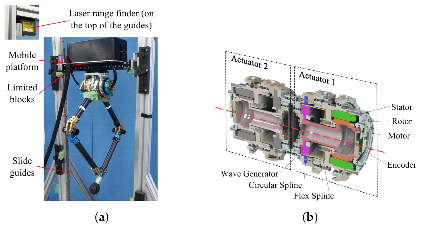
Figure 1. (a) Robot prototype; and (b) structural profile of actuation module.
Applsci 11 01421 g001
Figure 2. (a) Output torque test setup; and (b) relation between output torque and input current in actuator. The blue and red lines are theoretically calculated data and fitting result of actual measured value, respectively. We can consider that the actuator is sufficiently linear but still has certain friction in reducer part. Because of the limitation of the experimental facility, this test only recorded the results in a limited range (from −20 to 20 A), while the relation outside the range is considered as the same.
Applsci 11 01421 g002
Figure 3. Comparison of serial and parallel legged structure: (a) serial structure; and (b) parallel structure.
Applsci 11 01421 g003
Figure 4. Maximum requirements of (a) torque and (b) motor speed in vertical jumping to different target heights (5.5 kg robot), with serial and parallel structures respectively: (a) the value of serial hip is always at 0, while the other three curves (serial knee, parallel hip, and parallel knee) are overlapped; and (b) the value of serial knee is much higher than the other three overlapped curves (serial hip, parallel hip, and parallel knee). Thus, the requirements of actuator with parallel structure are more balanced than those of serial.
Applsci 11 01421 g004
Figure 5. Virtual model control diagram: (a) basic structural model of parallel robot leg; and (b) corresponding virtual model.
Applsci 11 01421 g005
Figure 6. State estimation diagram in three different states in one hopping period.
Applsci 11 01421 g006
Figure 7. Framework for simulation and fitting relation between takeoff stiffness, bottom height, and final jumping height.
Applsci 11 01421 g007
Figure 8. Data recorded during single landing–jumping motion. From top to bottom: leg length; motor current of Joint 1; toe velocity in vertical direction; and toe acceleration in vertical direction. In the graph, black circles represent the moment of change in leg length and motor current. Obviously, the motor current can be used to detect the touchdown information earlier than the leg length.
Applsci 11 01421 g008
Figure 9. Photographs of robot leg during continuous constant height hopping. Initially, the leg is hopping on a stool; at 1.68 s, the stool was removed and the leg then fell to the ground.
Applsci 11 01421 g009
Figure 10. Summit hopping height during continuous constant height hopping. The black dashed line is the set target summit height; orange short solid lines represent actual calculated heights based on the measured hang times. At the initial moment, the measured value is zero because the leg’s summit height cannot be calculated before the first touchdown.
Applsci 11 01421 g010
Figure 11. Data recorded during constant height hopping: (top) leg length; and (bottom) motor current of Joint 1.
Applsci 11 01421 g011
Figure 12. Photographs of robot leg hopping to different summit heights. Distance values in the images are measured from ground to toe.
Applsci 11 01421 g012
Figure 13. Summit hopping height during continuous hopping to different heights.
Applsci 11 01421 g013
Table 1. Performance parameters comparison of actuator between MIT Cheetah and our design.
Total Diameter (mm)Reduction RatioMax. Output Torque (Nm)Max. Torque– Radius Ratio
MIT Cheetah1251:5.81742.8
This paper701:311243.5
Publisher’s Note: MDPI stays neutral with regard to jurisdictional claims in published maps and institutional affiliations.