1. Introduction
The reduction of car weight is a topic of high importance in the automotive industry. A lighter car has an increased acceleration, and thus an improved performance. Moreover, this weight reduction reduces material cost, improves fuel efficiency, as well as reduces vehicle exhaust emissions. According to Li, et al. [
1], for every 100 kg weight reduction of light transport vehicles (LTV), their fuel consumption will be decreased on average by approximately 0.4 L/100 km, and thus their CO
2 emissions will be mitigated by 8–11 g/km. There are several ways to reduce car weight, such as the use of lighter materials in manufacturing, the downsizing of the car, and the removal of unwanted material from car components [
2]. One of the most implemented material-removal methods is topology optimization (TO).
TO is a popular optimization procedure that is applied for both research and manufacturing purposes. It is a mathematical method that optimizes the distribution of the material spatially in a design domain under the given objective functions, boundary conditions, and constraints. This can result in significant material savings of the structures while their mechanical strength is either maintained or enhanced. The TO, together with the size and shape optimization, constitute the three categories of the so-called structural optimization (SO) [
3]. The most common approaches for solving the TO-problem are the Solid Isotropic Material with Penalization (SIMP), the Bidirectional Evolutionary Structural Optimization (BESO), and the level-set based optimization [
4]. A description of the TO problem along with the SIMP approach that was applied in this research work is presented thoroughly in
Section 2.
In general, TO finds many applications in the automotive industry and in mechanics, where the weight savings can be remarkable. The car doors, the suspension systems, and the brake systems are some of the most common topologically optimized components in literature. One of the first publications on TO applications in the automotive industry is the work of Yang and Chahande [
5]. In their research paper, they optimized three models, including a truck frame, a deck lid, and a space frame structure, by using the traditional compliance TO method with an in-house TO software in Ford Motor Company. Another worth mentioning example is the optimization of the automotive tailor-welded blank door either by Shin, et al. [
6] or by Li, et al. [
7]. Shin, et al. [
6] applied compliance TO in the first place, followed by a size/shape optimization, while Li, et al. [
7] utilized the benefits from the BESO. Kong, et al. [
8] optimized a spring lower seat from a suspension system by using a topology and topography optimization approach. Li and Kim [
9] conducted multi-material compliance TO with SIMP as an interpolation method of an engine cradle and a cross-member of a chassis frame. Cavazzuti, et al. [
10], in their study, optimized a Ferrari F458 chassis with the SIMP method. A conceptual design of an engine cradle was developed by Li, et al. [
1] using a combined size, shape, and compliance TO. Sudin, et al. [
2] applied the SIMP method to optimize the mass of a brake pedal. Concerning the optimization of brake calipers, only a few works are found in the literature. Mastinu [
11] optimized both the brake caliper and the upright of a racecar with compliance TO. Ballo, et al. [
12] developed a lightweight design of brake caliper implementing the SIMP approach. Farias, et al. [
13] optimized a brake caliper in order to reduce both its weight and its heat transfer. On the other hand, Soh and Yoo [
14] optimized the shape of a brake caliper for squeal noise reduction. Finally, Sergent, et al. [
15] optimized the mass of an opposed piston brake.
The optimized structures in all these examples are characterized by their considerable weight savings or/and their performance improvements compared to their initials designs. However, the majority of the presented design solutions were conceptual numerical designs and not manufactured parts. It seems that TO in its current state of the art is mainly used for design inspiration and not for production [
4]. The optimized parts are characterized by their design complexities, which make AM with 3D printing the most appropriate manufacturing method for them. A thorough review of TO for AM is presented in the recent research work of Zhu, et al. [
16]. On the other hand, the redesign of the optimized designs contributes to the overcoming of these complexities and makes their manufacturing feasible by the conventional manufacturing processes (CMP). In addition, it and can eliminate possible overhangs at the 3D-printing parts. However, it can be time-consuming and, in some cases, challenging. In addition, the 3D printed parts can contain discrepancies compared to the numerical solutions.
The scope of this research work is to apply the TO in a real automotive component in order to identify benefits, challenges, limitations, as well as trade-offs in its implementation in the overall product development process, from an idea to an end product. For this reason, a case study of a front and a rear caliper, intended for a student racecar, is presented here. The brake calipers were designed, optimized, validated, as well as 3D printed in titanium with selective laser melting (SLM). A comparison between the numerical and the manufactured components contributed to the identification of possible deviations of the 3D printed parts. Designers and engineers interested in TO, AM, and automotive engineering can exploit the results of this research paper.
The rest part of the paper is composed as follows: In
Section 2, the general TO problem, together with the SIMP method, is introduced. The essential theory about brake calipers is described in
Section 3. The applied methodology in this research work is presented thoroughly in
Section 4, while
Section 5 includes the results of the optimized calipers. In
Section 5, the challenges in the implementation of TO in manufacturing are discussed based on the findings in this paper. Finally,
Section 6 and
Section 7 present the most important conclusions and the possible research possibilities, respectively.
2. The General Structural Optimization Problem and the SIMP Approach
At the general structural optimization (
SO) problem, an objective function of a structure, f(x), such as manufacturing cost, strain energy, stress, and displacement, to mention a few, should be either minimized or maximized with respect to the given boundary conditions (equilibrium constraints), behavioral, and design constraints. Hence, the optimization problem can be described as [
17]:
In the case of a density-based TO problem of a structure, its design domain Ω is discretized to finite elements. A binary value is assigned to their density
ρe; 1 for required material, and 0 for void. Hence, the nested mathematical formulation, based on the homogenization theory developed by Bendsøe [
18], is the following:
The f(u(ρe), ρe) is the objective function, the ρe, in the state function u(ρe), is the density of each element in the design domain Ω. Gj(u(ρe), ρe) are the constraints, and V is the total volume of the structure. The most implemented objective function is the compliance of a structure. Compliance is the reciprocal of the stiffness, so in other words, by minimizing the compliance, the stiffness of the structure is increased.
The most challenging part of the solution of the TO problem is the calculation of the elastic modulus. The homogenization theory uses an effective elasticity tensor to describe the mesotropic properties of a structure [
19]. The above formulation of a discrete TO problem resulted in the known “checkerboard” structural problem [
20]. Solving the TO with continuous variables by interpolation could overcome this limitation. A popular interpolation method is the SIMP [
21]. According to SIMP, the overall elasticity of a structure is calculated by the following formula:
In this case, a continuous value is assigned to the elements’ density, ρe. Furthermore, a minimum density ρmin ≠ 0 was used as a lower bound of density in order to avoid a calculation of a zero structure’s elasticity. The “penalization” of the intermediate finite elements; elements with density ρmin < ρe < 1 is conducted by the penalty factor, p. In other words, the SIMP method prevents the formation of the intermediate elements by increasing the structure’s density to an exponent equal to p. According to Sigmund (2001), the ideal value of the penalty factor is three. Hence, the introduction of this factor reduces the elasticity, and in turn, the global stiffness is reduced.
Allaire, et al. [
19] argue that SIMP is an over-simplified version of the initial homogenization theory and does not consider anisotropy. Despite this fact, the SIMP method is broadly implemented due to its simplicity. A plethora of different commercial software, software modules, as well as off the self-algorithms, has developed in the last decades in parallel with the continuous development of computational power in order to solve SO problems. The majority of these tools are still based on the traditional compliance TO-theory. The SIMP approach will also be applied in this research work.
3. Brake Calipers
A brake system is responsible for the deceleration of a vehicle, and thus is a vital part of driver’s safety. The brake system is designed to both slow down and halt a vehicle by transforming its kinetic energy into heat while applying friction forces to the vehicle axles [
22]. The most common brake system is the disc brake, which was initially developed in 1951 for racecars application. Just a few years later, in 1955, disc brakes were first used for mass production in the automotive industry, due to their success, on the Citroen DS model [
23]. The disc brakes are steadily replacing drum brakes in order to overcome the potential brake power loss of the latter, also known as brake fade [
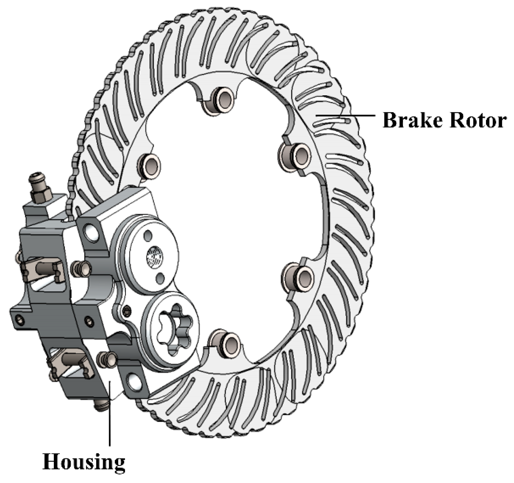
22]. The most crucial component of a disc brake is the caliper that presses a pair of brake pads against the brake’s disc, also called rotor, and thus slows down their rotational speed. In the case of hydraulic disc brakes, when the driver pushes the brake pedal, hydraulic pressure is applied by the brake fluid on the caliper’s one or several pistons, and these, in turn, force the pads against the disc [
24].
Figure 1 depicts a disc brake.
The design of calipers is challenging and should be developed with respect to some technical requirements. According to Farias, et al. [
13], the calipers must be stiff, light, and heat-resistant. Brake calipers require acceptable stresses and deflections under multiple load cases. It is important to mention that any crack on a caliper can lead to an instant brake fluid leak that results in brake malfunction. Thus, a high caliper stiffness provides a uniform pressure distribution on the brake system, which ensures short brake pedal travel, ride quality, and vehicle safety [
15]. The term unsprung mass is broadly used to describe the total mass of the suspension, wheels, as well as other components connected to them. On the other hand, sprung mass consists of the supported by the suspension vehicle’s body and components. In the case that the vehicle’s brakes are mounted outboard, they are considered part of its unsprung mass [
12]. As has already been mentioned, a minimization of the vehicle’s mass increases its performance. Therefore, the reduction of brake caliper mass is of high importance. The applied friction forces between the brake pads and the rotor result in heat concentration inside the brake system. A low thermal resistance, together with insufficient ventilation of the brakes, increases their thermal deformations resulting in a smaller friction coefficient and, in turn, less braking force [
13]. It seems that compliance TO of the brake calipers could reduce their weight while increasing their stiffness. Moreover, the creation of voids in the calipers’ structure will increase their ventilation and heat dissipation.
A brake caliper is mainly comprised of housing, brake pads, and pistons [
12]. The housing is usually made of cast iron, the brake pads of semi-metallic, organic, and ceramic materials, and the pistons of plastic, aluminum, or chrome-plated steel. Generally, there are two main types of brake calipers: the floating and the fixed calipers [
25]. The calipers mostly differ in terms of design, mounting, and operation. On the one hand, the floating calipers move relative to the rotor. Furthermore, they have one or two pairs of pistons only on the inboard side of the rotor. When the brakes are applied, the fluid pressure moves the piston(s), which then pushes the entire caliper creating friction from the brake pads on both sides of the rotor. The floating calipers are prone to sticking failure resulted from dirt or corrosion at their moving components. This can cause extreme heating of the rotor, vehicle’s steering vibration, and reduced fuel efficiency [
26]. On the other hand, fixed calipers, as their name implies, do not move but are rather fixed with bolts to the caliper bracket. In addition, they have two to six pairs of pistons arranged on opposing sides of the rotor [
12]. The fixed calipers, due to their multiple pairs of pistons, as well as their intricate brake fluid routing, have a more complicated geometry and are more expensive compared to the floating calipers. However, they are preferred for their performance because they have predictable braking behavior and due to the fact that their pads have balanced wear and less tapering [
27].
In the rest part of this section, the fundamental formulas describing the kinetics and dynamics of a vehicle and its brake system are presented. The thermodynamics were neglected in this research work. Interested users should also be referred to the works of Milliken and Milliken [
28], Heisler [
24], and Jazar [
29] for thorough details.
3.1. Brake System Kinetics
The main job of an automotive brake system is to slow down a vehicle by applying a friction force. Hence, the kinetic energy, E
kinetic, of the vehicle is converted to thermal energy, E
thermal, which in turn is absorbed by the brake system. A simplified formula describing the relation between a vehicle’s mass with a given velocity and the difference in temperature of the brake system is the following [
24]:
where
: mass of the vehicle
: velocity of the vehicle
: mass of the brake system
: specific heat capacity of the brake system
: temperature change in the brake system
In a disc brake, the clamping force of the calipers to the brake discs is translated to a friction force opposing the disc’s rotational direction and thus can be expressed by the equation:
where
: friction force on one wheel
: clamping force
: friction coefficient between pad and disc
: brake torque on the wheel
: effective pad radius
: number of friction faces
The friction coefficient will be varied according to the applied pressure and temperature surface roughness connected to the wear. In addition, the moment of the disc is assumed constant throughout the rotating wheel assembly. In order to exploit the capabilities of a braking system, the tire should be the limiting factor, and both the front and rear axles should be on the verge of locking. A mathematical expression of that is
where
: max wheel torque, given by the tire-ground friction coefficient and vehicle weight
: friction coefficient between tire and ground
: gravitational acceleration constant
: deceleration proportional with
The Formula (6) describes the maximum negative acceleration without exceeding μ
tire. In addition to the wheel torque, other parameters such as the aerodynamic drag, the drivetrain losses, the gear meshing, the oil viscosity, and the rolling resistance can contribute to the braking force [
24].
3.2. Vehicle Dynamics
Three are the most applied models for the vehicle dynamics calculations that characterize its ride quality, such as vehicle’s transmissibility, suspension travel, and tire deflection together with the tire-ground adhesion: the quarter car model, the 2-DOF half-car model, and the 4-DOF half-car model. These models are based on the following assumptions: rigid unsprung and sprung masses, linear suspension spring, and viscous damping. In addition, the tire in these models is represented as a combination of spring and damper. However, the tire damping is omitted in the analysis of all models [
30]. The used models in this research work were the quarter car model and the 4-DOF half-car model.
The quarter-car model represents one-fourth of a vehicle. Its degrees of freedom are the translational displacement of both the sprung and unsprung mass, making it a 2-DOF model.
Figure 2 illustrates a quarter-car model [
29].
Here, the
ms and the
mu represent the quarter sprung and unsprung mass of a car, respectively. In addition,
ks,
cs represents the spring stiffness and damper coefficient of the shock absorber. Finally,
ku and
cu are the spring-damper effect of the tire. Both the sprung and the unsprung masses can be calculated by the following equations:
Translated into matrix form, we get the following equation of motion:
where
This model was utilized for the calculation of the suspension vibration and helped the authors to identify the effect of a potential unsprung mass reduction in the case study of the racecar. However, this model takes into account only the bounce motion of the vehicle. For this reason, the 4-DOF half-car model was used in addition to the quarter-car model.
The 4-DOF half-car model was exploited for the pitch angle estimations, given the dynamic load distribution between the front and the rear axle and with regards to the front and rear braking load. At the 4-DOF half-car model depicted in
Figure 3, the half body (
m) of the car as well as one front (
m1) and one rear wheel (
m2) are presented. The
kt1 and
kt2 are the spring stiffness of the tires. Furthermore, c
1 and c
2 are the damping coefficients, and
k1 and
k2 the stiffness of the shock absorbers. Finally, the illustrated rigid bar in the model represents half of the car’s mass,
m, with a lateral moment of inertia,
Iy.
The equation of motion from the quarter-car model, Equation (9), is used in this model too. However, in this case, the
x,
m,
F,
c, and
k matrices are [
29]:
Both quarter-car and 4-DOF half-car models can be utilized as simplified representations of a vehicle’s brake system. Furthermore, they can show that for constant spring stiffness and damping coefficient, a small increase of vehicle’s mass will increase the total force, F. This will result in longer wheel travel and, thus, in an increasing damper frequency. The increased damper frequency, in turn, will lead to less tire-ground adhesion. A solution to the problem could be the increase of both damper coefficient and spring stiffness, but this can be managed with heavier components adding mass to the unsprung mass. Hence, the TO could be an alternative for the minimization of the vehicle’s unsprung mass and the optimization of the braking system.
4. Methodology
In this research work, the development of front and rear brake calipers for a student racecar is presented. The in-house calipers were based on the commercial ISR calipers: the ISR 22-048 for the front caliper and the ISR-049 for the rear. Both are fixed calipers originally designed for 125cc bikes and Formula SAE racecars. However, the ISR 22-048 (front) uses four pistons while the ISR-049 (rear) two. The assemblies of the ISR calipers are illustrated in
Figure 4.
At the beginning of this research, the identification of mass reduction possibilities was implemented. For this reason, an analysis of the vehicle’s braking behavior, together with the ISR calipers, was conducted. Then, the calipers were optimized using a three-level optimization procedure in order to reduce their weight, and thus the total unsprung mass of the racecar. A reduction of the vehicle’s unsprung mass could improve its performance. The implemented methodology is depicted in
Figure 5.
The analysis of the vehicle and the ISR calipers comprises two main tasks: the lap time simulation of the vehicle in Matlab and the physical testing of the commercial ISR calipers using an in-house test jig.
The calipers were a part of the disc brakes of the racecar, which in turn were connected to a kinetic energy recovery system (KERS). The utilized KERS had limited torque output at the motor’s top rpm. Thus, the vehicle’s top speed was used as the dimension load. As has already been mentioned in
Section 2, it is a good engineering practice to use the car tires as the limiting factor for the brake system. The chosen tires for the racecar were the Continental C19. A dynamic tire model was developed in MATLAB in order to conduct a lap time simulation. This model was based on the Continental’s technical specifications and the Pacejka M5.2 tire model [
31] and is given by the following tire formula:
where
: force or moment resulting from a slip parameter
: slip parameter
: stiffness factor
: shape factor
: peak factor
: curvature factor
Five lap time simulations were implemented for five different torques, range 300–700 Nm with a 100 Nm step. These simulations contributed to the calculation of the brake system’s load case using the above tire model, the vehicle load transfer, as well as the aerodynamic- and motor representations. Furthermore, the minimum braking force that did not compromise the lap times was identified. Finally, the temperature development on the discs was estimated based on empirical data from previous autocross runs. These data were collected by an INFKL 800 °C IR brake temperature sensor placed into the hydraulic system of the disc brakes.
Figure 6 depicts the results from the lap simulations of the calculated braking distance and velocity of the car and the distribution of the longitudinal forces, in the case of braking, from 120 km/h to 0 km/h. In addition, a temperature-time diagram is presented based on the sensor’s data.
The conducted simulations in Matlab showed a convergence of maximum brake force in cohesion to the tire model. Torque values above 600 Nm gave slower brake time as the brake force exceeds the tire’s grip limit. In addition, from the longitudinal forces-time graph (graph c), it is observed that it is required a 0.8 brake balance between the front and the rear calipers. Finally, the empirical data of the temperature on the disc showed that a temperature up to 450 °C was expected on the disc brakes. According to Low [
32], the main part of the generated heat, approximately 90–95%, is absorbed by the brake disc, and the rest 5–10% is distributed among the pads, the pistons, the brake fluid, and the caliper housing, assuming little to no heat dissipation. It is clear that the energy transferred during braking is highly related to the thermal resistance of the pads and the disc surface. Hence, the calipers also should be heat-resistant, and this is something that was taken into consideration in the choice of their production material.
The maximum allowed pressure on the brake master cylinder, according to their technical specifications, is 20 MPa. A pressure test was conducted at the ISR calipers, using an in-house test jig, and the maximum displacement in the y-direction of the front and the rear caliper, at 20 MPa, found 0.5 mm and 0.4 mm, respectively. In consequence, these were the maximum allowed displacements for the in-house developed calipers too. After the analysis of the vehicle and the ISR calipers, an optimization procedure of the calipers for their weight reduction was implemented on three levels, based on the Sudin, et al. [
2] guidelines: downsizing of the vehicle, use of lighter materials in manufacturing, and removal of unwanted material from vehicle components.
At level one, new design concepts of the calipers were developed in SolidWorks by using reverse engineering of the commercial ISR calipers. The main goal at this point was either the reduction of the calipers’ components or their downsizing. Thus, several design concepts were created and validated with respect to the ISR calipers’ initial designs, the weight trade-offs among their components, and their interaction with the car’s rim and upright. A crucial decision was to decrease the number of pistons from four to two in the front caliper. On the one hand, a four-piston caliper has an increased piston area and, thus, a reduced hydraulic pressure compared to a dual-piston caliper. However, the use of more pistons increases the risk of seal failure as well as the maintenance time. On the other hand, a dual-piston caliper could result in smaller design space and a less complex assembly due to the reduction of its components, but it contains a heavier housing to support its increased hydraulic pressure. Thus, there is a trade-off between the weight of the housing and the weight of the other caliper’s components. The authors decided to develop a design concept of a dual-piston front caliper reducing its complexity and overall volume. Hence, both front and rear will be fixed dual-piston calipers. Furthermore, the initial design space of their housings was expanded as much as possible, with respect to the spatial placement of the wheel components, in order to increase the design flexibility for the TO algorithm. These design concepts, “design space assemblies”, were validated in ABAQUS for the same load case and boundary conditions with the conducted physical test of the ISR calipers.
At the second level of optimization, an exploration of the material choices for the calipers was conducted. All the materials of the calipers’ components, except the housings, were kept the same, thus from this point, the optimization focus was on housings only. It was decided that the optimized housings will be 3D printed using SLM. Hence, material research was done among the available 3D printing materials. Three were the predominant materials: AlSi10Mg, Steel MS1, and Ti6Al4V. On the one hand, the AlSi10Mg was the lightest material with the lowest specific gravity (2.7 g/cm
3) compared to the other two available options, the Steel MS1 (8.1 g/cm
3) and the Ti6Al4V (4.4 g/cm
3). Concerning the used case study in this paper, every gram counts in the development of calipers for a racecar. However, the calipers of a racecar are exposed to high braking forces and temperatures. Hence, the Ti6Al4V with an exceptional yield strength (1147 MPa), even at 500 °C (890 MPa), was considered an excellent choice [
33].
Concerning the third optimization level, the housings of both front and rear calipers were topologically optimized, for weight reduction, without sacrificing their stiffness. The TO of the housings is divided into five steps; (1) Pre-processing, (2) Topology Optimization (TO), (3) Post-processing, (4) Validation, and (5) Production.
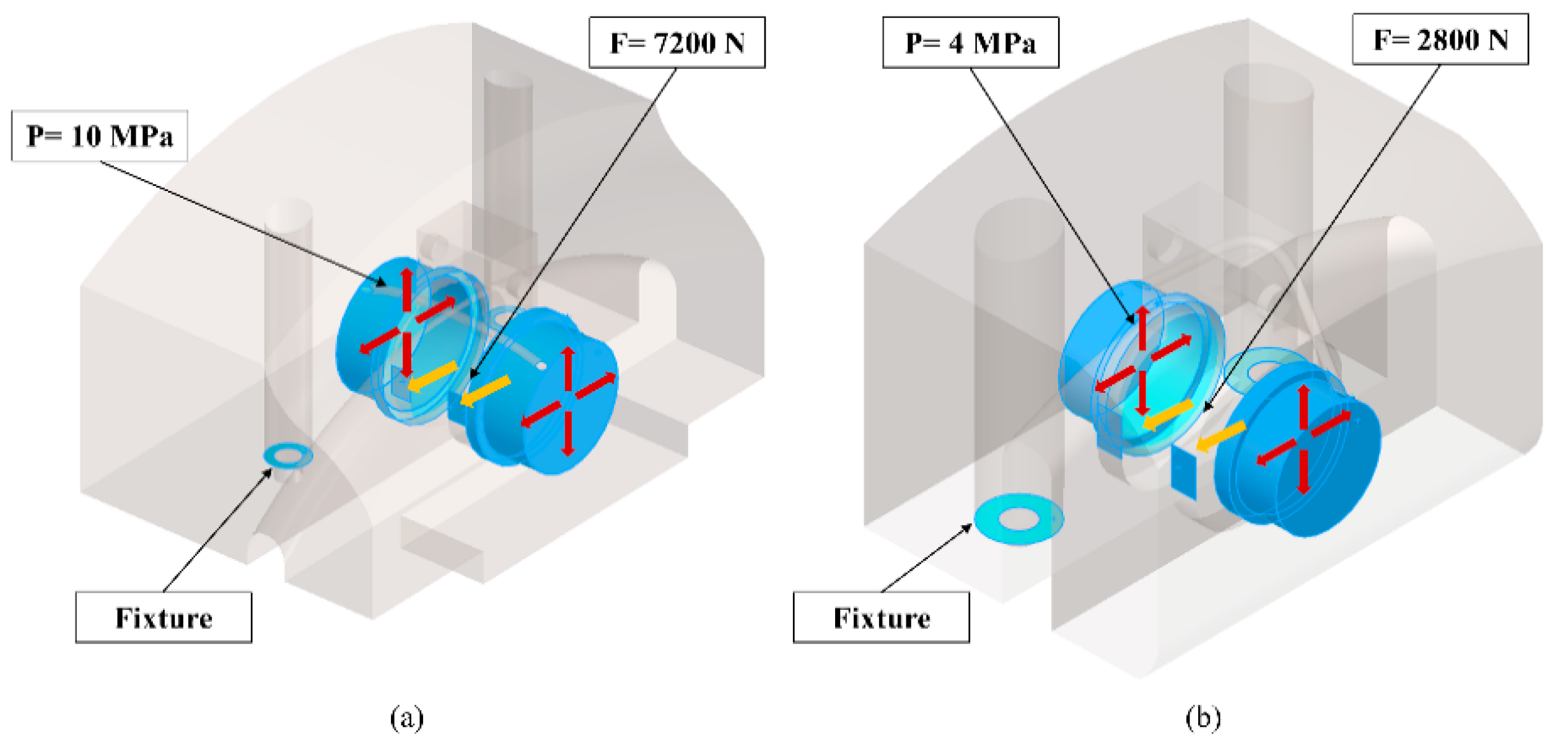
The pre-processing consists of the computer-aided design (CAD) of the housings in SolidWorks and the finite element analysis (FEA) of them in ABAQUS. The initial design concepts of the calipers’ housings were created in SolidWorks with respect to the ISR brake calipers. The CAD files were exported and transferred to ABAQUS for FEA. The applied load case in the FEA was for maximum brake force at 120 km/h and warm tires. On the one hand, a pressure,
P = 10 MPa, and surface traction,
t = 7200 N, were applied at the pistons’ area of the front housing. Furthermore, the housing was fixed with two bolts to the upright. These bolts were replaced in the simulations by two fixtures to reduce the simulation time. On the other hand, the pressure and the surface traction were
P = 4 MPa and
t = 2800 N, respectively, at the housing of the rear caliper. The same boundary conditions were also applied in this case. The design space, as well as the used forces and boundary conditions in both housings, are presented in
Figure 7. The 3D models were discretized using 1 mm tetrahedral finite elements, resulted in 2,334,921 and 1,981,349 total elements for the front and the rear housing, respectively. The assigned material was an anisotropic Ti6Al4V with Young’s modulus
EXY = 120 GPa and
EZ = 110 GPa, Poisson’s ratio
ν = 0.31, and density
ρ = 4.41 g/cm
3. The material properties were taken from the EOS data sheet, which was the used material of the 3D printed housings.
Different TO software was used for the two case studies for comparison reasons. On the one hand, the housing of the front caliper was optimized with a condition-based algorithm in ABAQUS. This algorithm is based on the SIMP approach. The minimization of the model’s strain energy was used as objective function while a volume fraction, equal to 7.45% of the initial design space, was used as function constraint. This volume fraction could lead to a 160 g housing. The 160 g target was set with regard to the targeted stiffness properties of the ISR caliper. Optimizing with volume constraints is a process of experimentation with different values of volume fraction until the stiffness goal is reached. Furthermore, the surfaces for the pistons and the fluid channel were the “frozen areas”, and thus were excluded from the available design space. Finally, 300 design cycles were used as maximum limit. On the other hand, the housing of the rear caliper was optimized in ANSYS Discovery software. This software uses a sensitivity-based algorithm for the optimization and is GPU-based that promises automatically generated CAD models in less than an hour. The applied TO here was also the traditional compliance optimization where the minimization of strain energy was used again as objective function and the volume as function constraint. However, in this case, the volume was set equal to 8.55% of the initial design space, which could lead to a 75 g housing. The surfaces for the pistons and the fluid channel were defined as frozen areas also here.
At the post-processing step, the optimized design solutions were imported as STL files to SolidWorks for redesign. Usually, the complex geometries of the optimized designs are making challenging their production with CPM. For this reason, a redesign procedure based on the optimized solutions takes place after the TO. However, when TO is oriented to AM, this step can be omitted. In this study work, it was decided to manufacture the housings with SLM 3D printing. Thus, the authors utilized the 3D printing flexibility and redesigned only the interacting surfaces and the crucial areas, such as the piston chambers, the seal surfaces, and the fluid channels. The latter was designed with a minimum angle equal to 30° in relation to the build plate in order to be free of support material. No tool could remove the support material inside the fluid channels. In addition, “power surfacing” was used in SolidWorks for the whole geometry. This feature smoothens the surface of the models and contributes to the mitigation of sharp areas that can lead to both stress concentrations and overhangs later in 3D printing. Finally, the optimized housings replaced their initial designs in the caliper assemblies. The assemblies were mirrored between the right and left wheel resulting in an equal force path on the left and right uprights. The symmetrical brake calipers can lead to a balanced brake performance of the vehicle.
The validation of the final designs was conducted in two steps. In the first step, only the housings of the calipers were checked with an FEA simulation similar to this at the pre-processing. Consequently, a second FEA simulation was implemented using assembly designs for the calipers. Each assembly consisted of a housing, two pistons, two bolts, a brake segment, and a foundation element acting as the upright. The brake pads were neglected from the validation studies to reduce the simulation time. However, the brake discs were made much thicker to compensate for the brake pads’ thickness loss. This resulted in a load case of extremely worn brake pads. The used loads were: pretension of the bolts with bolt loads,
F = 17 KN, the pressure inside the housing at the pistons’ area,
P = 16 MPa, and torque to the brake disc in normal driving direction,
Mb = 600 Nm. On the other hand, the validation of the rear caliper was set with a pretension load
F = 17 KN, a piston pressure
P = 8 MPa, and a brake disc torque
Mb = 300 Nm. Finally, the same boundary conditions were used in both cases, as they are shown in
Figure 8.
The final step in the presented methodology was the production of the calipers. Specifically, this step consists of five tasks, the geometric dimensioning and tolerancing, the 3D printing preparation, the manufacturing of the housings, and the post-treatment of the 3D printed parts as well as their analysis.
The possible post-machining process requires careful tolerancing and dimensioning of the housings, specifying the allowable deviations in both geometry, size, weight, and surface quality. Hence, technical drawings of the housings were developed based on ISO TC213. In addition, the interacting surfaces with the other components, such as the seals and the pistons, were designed according to the components’ standards and specifications. For example, it is recommended that the pistons’ surface finish should be 0.4 μm. That was noted in the technical drawings and will be measured later at the 3D printed parts.
As has been already mentioned, SLM 3D printing was chosen as a manufacturing method for both housings. Hence, a 3D printing preparation of the 3D models should be conducted. The support structure was used on features with more than a 30° overhang relative to the 3D printer plate. In addition, the fluid channels were free to support material. In general, additively manufactured models can suffer from poor surface finish and dimensional discrepancies making inevitable the post-machining of their surfaces interacting with other components such as bolts, bearings, and fitting parts. For this reason, the housings’ surfaces that interact with the other caliper components were designed to be printed with 5 mm extra material.
Another challenge in 3D printing is that the 3D printed parts suffer from uneven material heating between their layers resulting in internal stresses and material anisotropy [
34]. Hence, a 12-h curing process was conducted on the 3D printed parts at the post-treatment step. The housings were heat-treated at 740–900 °C over a period of up to 12 h for internal stress relaxation without any impact on their geometry [
35]. After the curing process, the support material was removed from the housings.
Then, their weight and critical dimensions were measured in order to identify possible differences from the 3D models as well as post-machining needs. In addition, an in-house designed assembly jig and a test jig were developed for the assembly and the testing of the calipers. However, the post-machining of the housings, the assembly of the calipers, and their mechanical testing were planned for future work.
6. Topology Optimization for Manufacturing
The TO is mainly used as a design tool. However, its utilization in manufacturing is possible but challenging. There are many parameters that should be taken into account, such as the overall optimization method, the manufacturing method as well as the TO approach, and its applied software.
The TO procedure is dependent on the overall optimization method and cannot be seen separately. The followed optimization method in this paper was implemented in three levels: the development of new caliper design concepts using less and downsized components, the exploration of lighter and stiffer materials in the production of the calipers’ housings, and the removal of unwanted material from them by using TO. First, the modifications and changes made in the caliper assemblies could optimize the structures and save material without any loss in their performance. For example, the reduction of the pistons in the front caliper from four to two could reduce its weight. Secondly, material exploration was conducted for the housings. The AlSi10Mg was the lightest material among the available options; however, the Ti6Al4V was instead used due to its exceptional yield strength, even in high temperatures. In addition, the 3D printing preparation of the models should take into account the 3D printing material. For example, it is recommended to use support material for an overhang angle bigger than 20–30° for titanium parts, while this angle limit is increased to 45° for parts made by aluminum. Third, the TO procedure focused on the housings, which were the heaviest components of the calipers. A small change in the overall optimization procedure could also have a high impact on the TO procedure. For example, the number and the spatial placement of the caliper’s components could affect the design space of the housings, and thus the results of the conducted TO.
The manufacturing method of the housings has been decided from the beginning of this optimization work and was the SLM 3D printing. The reason for that was to avoid the time-consuming redesign step of the optimized solutions. This does not mean that the topologically optimized designs are only oriented to AM, but it highlights the need to redesign them before their manufacturing by CPM. When TO is oriented to 3D printing, the redesign at the post-processing of the design solutions can either be omitted or limited to the interacting surfaces and critical areas of the structure. Hence, topologically optimized designs can be manufactured directly or with small modifications. Moreover, a 3D printing preparation of the design should be committed, taking into account the 3D printing method, the use and removal of the support material, the 3D materials and their anisotropy, and possible needs for post-machining of the 3D printed parts. One example was the non-use of support material inside the fluid channel due to its impossible removal after 3D printing. Another example is the use of additional material on interacting surfaces. The 3D-printing parts suffer from poor surface finish making their post-machining inevitable in order to get good surface quality. Thus, the use of 5 mm extra material to the crucial surfaces created enough space for the surface finishing tools. Moreover, weight and dimensional deviation should be expected in 3D printing. Hence, the designer should take into account these deviations both in design and TO, introducing the required tolerances.
The used TO method in this paper was the traditional compliance TO with the SIMP as an interpolation method. According to the theory, the SIMP method does not consider material anisotropy. However, it is good practice to use the SIMP method due to its simplicity, and apply an anisotropic material to the structure. When the amount of the intermediate finite elements is small, a good approximation of the anisotropic properties can be achieved. However, it is important to notice that the created anisotropy is static and not design-dependent. For this reason, a deviation between the calculated and validated material properties of the 3D-printed parts should be expected.
The choice of the TO software affects the optimization time and the quality of the results. Concerning the TO software, both ABAQUS and ANSYS discovery led to interesting design solutions that respected the given optimization goals and restrictions. Concerning the optimization time, the optimization of the front housing with ABAQUS was completed after 295 design cycles and, thus, took many hours compared to the optimization of the rear housing in ANSYS discovery that was completed in less than an hour. On the one hand, ABAQUS with the TOSCA optimization module is one of the most traditional TO tools with a plethora of choices for both the optimization algorithms, the objective functions, the optimization constraints, as well as the load cases and the boundary conditions. In other words, for all possible designer choices [
36]. On the other hand, the ANSYS discovery in this version (2020) is limited to simple load cases, basic constraints, and a sensitivity-based optimization algorithm that does not take the displacement of the structures into consideration, making it not ideal for multiple load cases and combined optimization goals. However, the software could cover the optimization needs of the rear caliper due to the used linear load case. Moreover, it offers real-time optimization in every design cycle, making the monitoring of the optimized results easier. ANSYS discovery live model predicted a 0.36 mm maximum displacement in the y-direction, which was close to the 0.33 mm displacement found in the validation study. It seems that its efficiency and accuracy as a GPU-based TO tool could be an interesting research topic in the future.


