1. Introduction
Composite steel–concrete structures can be seen as a solution to the arising struggle with climate change [
1,
2,
3,
4] as they combine efficient use of materials with the robustness and ease of assembly, but their advantages are still not used widely enough. The main setback for composite structures is the lack of construction-wise and cost-effective joints. It is especially apparent in the design of frames with the circular concrete-filled steel tube (CFST) columns, which as a result of a superior confinement effect have greater compressive strength and deformation capacity than their square counterparts [
5]. Such connections are considered non-straightforward, and because of this, they are not developed to the same degree as joints of square CFST columns. [
6,
7,
8,
9].
In recent years, a large-scale investigation of the new moment resisting joint with the curved endplates (
Figure 1) has been in progress. This includes experimental and numerical studies of the behaviour of the bolted endplates connection between a CFST column and a steel beam [
10,
11,
12,
13,
14,
15,
16], as well as analysis of the connections between a composite beam and a stainless or carbon steel concrete-filled column [
17,
18,
19,
20,
21,
22]. There are also studies by Tao et al. [
23] and Sheet et al. [
24] on the connections with through-column bolts, which were either parallel to the beam, or passed through the column in an “X” shape. Lastly, there is the study by Oktavianus et al. [
25], in which a diaphragm-like bolted endplate connection was analysed, but it would seem, that in case of this connection, unequal bolt force distribution should be anticipated, as it was reported by Yao et al. [
26].
Based on the Theory of Shells, it is known that curved plates develop thrust to resist the applied loads. The same happens in curved endplates, in which bolts are not only in tension, but also in shear. The degree of tension/shear force vastly depends on the flexibility of the plate and support conditions of the bolts: if bolts could move easily, then thrust would not develop. Thrust force decreases the axial load of the bolts and increases their shear. Because of this, conventional prying models are not suitable for the general case of the curved T-stub. Moreover, this also applies to the use of the Eurocode [
27] expressions for determination of the effective flange length, particularly in the case of estimation of the initial stiffness of the T-stub [
28].
This paper investigates behaviour of new moment resisting connection between circular CFST and steel beam by means of experimental and numerical studies. Two connections with curved endplates of identical geometry were tested, in which bolts were snug-tightened to establish firm contact between an endplate and the column, but in neither one firm contact was achieved. Further parametric study was utilised to explore the effects of gaps on stiffness, strength, and position of centre of compression in such joints. It showed that depending on the gap size and its position, not only the initial rotational stiffness, but also resistance of the joint is dependent on bolt preloading force. This finding led to the conclusion that without knowing the initial force in the bolts, it is impractical to calibrate the FEA model, as there are too many variables.
2. Materials and Methods
Experimental Investigation
Two connections of identical geometry 2B and 3B were tested. For the tests, a 1000 t capacity press was used. Geometry of the joints is presented in
Figure 1a. The characteristics of materials used for the tests were obtained experimentally and are presented in
Table 1 and
Table 2. Loading was divided into two steps. In the first step, an initial 50 t compression force in the column was introduced and maintained, then, in the second step, equal and opposite moments were induced by manually controlled hydraulic cylinders (
Figure 1). The ends of the column were fixed; in contrast, the ends of the beams were not restrained.
Vertical displacements of the ends of the beams were measured with two linear variable differential transformers (LVDT) per side to account for plausible torsion. These LVDTs were placed on the bottom flange near the loading gear. Lateral displacements of the beam ends were controlled with one LVDT, which was attached to the middle of the web. In addition to this, horizontal displacements of the endplates were measured by placing LVTDs in the middle of the bolt spacing: both in the compression and in the tension zones. For the redundancy of the measurements, the digital 2d image correlation technique was also tested, which proved to be accurate, but it did not show significant advantages in comparison to the conventional LVTDs.
Curved endplates were manufactured from a seamless CHS 219 × 10 pipe, which was cut into four equal pieces (the central angle of the endplate is equal to 90 deg.) The average throat thickness of the fillet weld joining the endplates with IPE 270 cantilevers was 4.44 mm. The endplates were connected to the cold formed CHS 219 × 6 column with four high-strength M12 × 35 HV bolts by using a regular wrench, and then the assembled columns were filled with the concrete.
Bolts were tightened by applying the full-strength torque to establish firm contact between the column and the endplate; however, no firm contact could be achieved. The bolt tightening force was not measured or controlled by any means. After tightening, the gaps at the ends of the plates were measured with the feeler gauges at three points (two corners and in the middle in accordance with
Figure 1). The measurements are presented in
Figure 2.
3. Results and Discussion
3.1. Experimental Results
All joints failed in the tension zone either by punching shear (
Figure 3a) or by fraction of the bolt (3B(L)). Non-fractured bolts from the tension zone were heavily bent (
Figure 3b), fractured bolts did not exhibit necking. Due to flaking of the limewash near the weld, plastic deformations in the middle of the top flange were visible (
Figure 4a). In contrast, the limewash layer was intact in the tension zone (
Figure 4b).
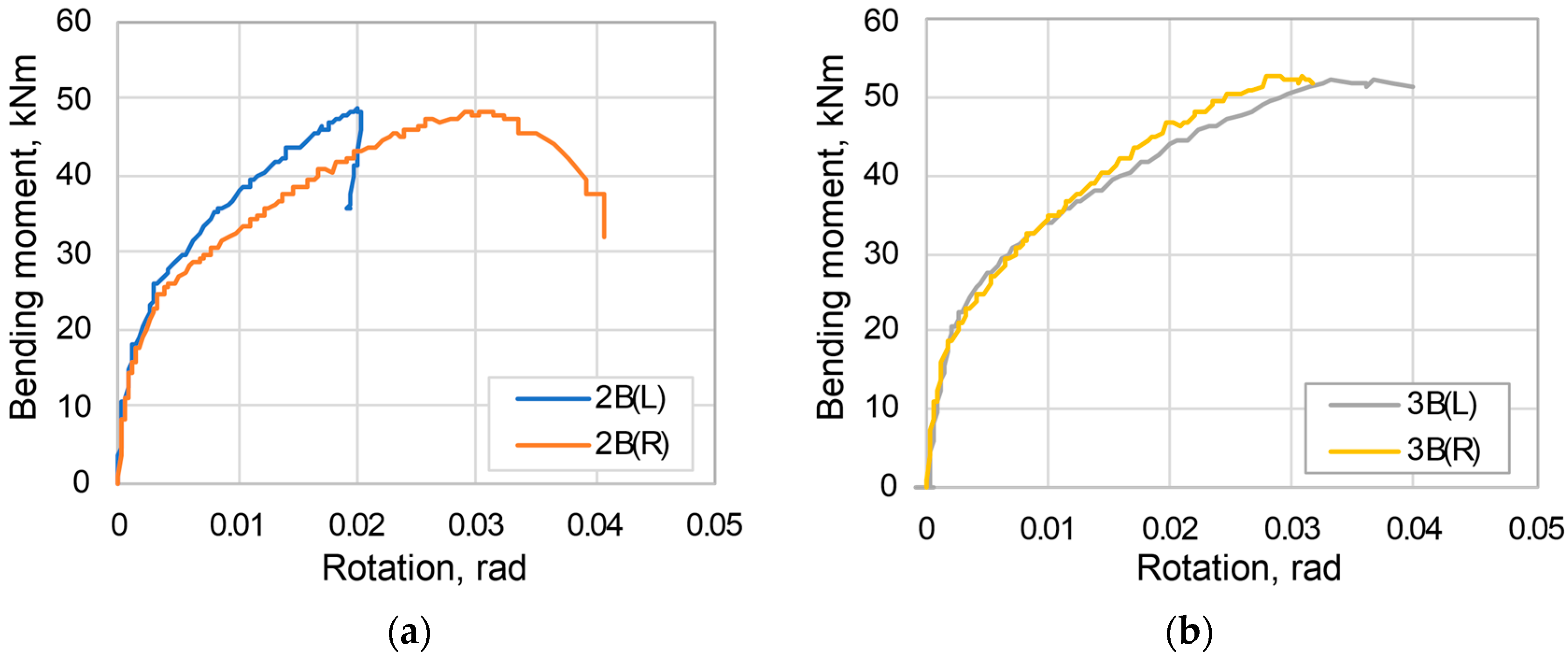
The experiments showed that the average initial rotational stiffness of the joints was 17,381 kNm/rad with standard deviation of 3293 kNm/rad and the ultimate bending moment capacity of 50.48 kNm with deviation of 2.41 kNm. Moment–rotation curves are shown in
Figure 5.
3.2. Finite Element Analysis
Simulations were performed in the ANSYS
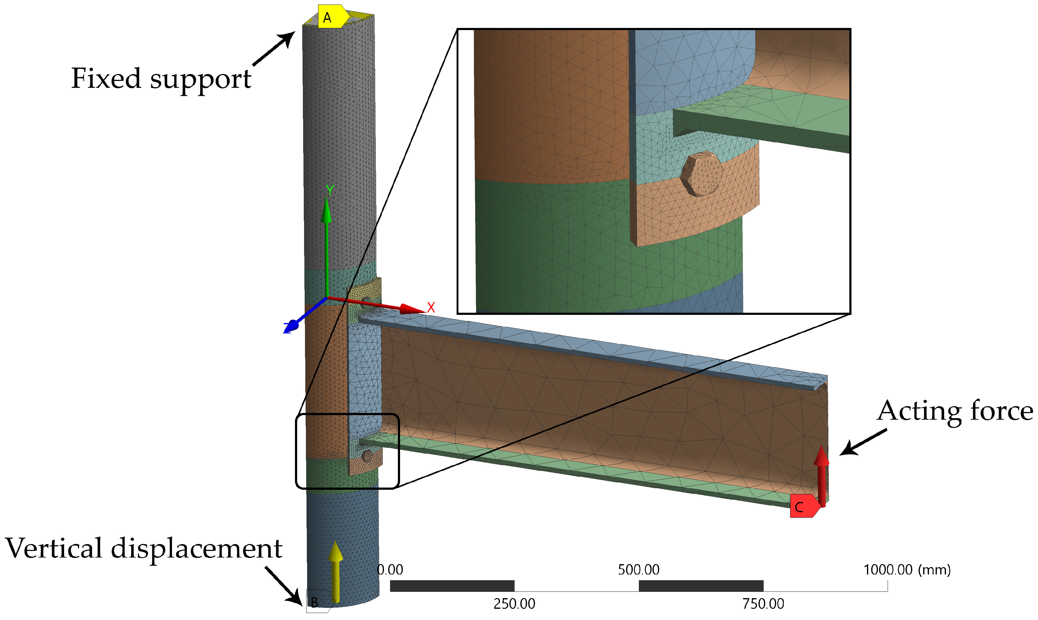
Static Structural analysis system. With account of the symmetry, only a quarter of the model was analysed, which then was meshed with the higher-order tetrahedral ten-node
SOLID187 elements (
Figure 6). After performing a mesh convergence study, different mesh sizes were used: 3 mm for bolts; 5 mm for extended parts of the endplate; 15 mm for the middle part of the endplate; 2.5 mm for fillet welds; 10 mm for the steel tube; 15 mm for the middle part of the concrete core. For the other parts, the default global mesh size of 83 mm was left. Additionally, mesh refinements were implemented near the wealds and in the tension zone of the steel tube. In these critical areas, mesh size was decreased in such a way that the endplate and the bolt hole would be meshed with four layers of elements along their thicknesses, which exceeds recommendations of Molitoris et al. [
29]. Another plausibility of assessing the mesh quality is to directly compare FEA results with the experiments [
30,
31].
The material model for the concrete was assumed to be linear elastic. In contrast, bolts and beams were modelled with elastic perfectly plastic material. Moreover, for the column tube, the multi-linear isotropic plasticity model (
Figure 7) was chosen to overcome problems with the convergence, which are related to the simulation of the punching shear fracture. Geometrical nonlinearities were not considered. The model was loaded in a similar sequence as the one in the experiment: the axial force in the column was introduced by displacement control loading during the first step, and a vertical force was applied to the end of the beam during the second step. In addition to this, the bolts were preloaded during the first step.
Fourteen frictional contact pairs were introduced: between the endplate and the column; the bolt heads and the endplate; the nuts and the inner surface of the column; the bolt shanks and the bolt holes; the concrete and the inner surface of the column. Additionally, the nut of the bolt in tension zone was split into six surfaces (
Figure 8) to even out concentration of the force. Augmented Lagrange formulation was used for all contacts with stiffness update at each iteration. The initial contact interface treatment was set to the “adjust to touch” option and all friction coefficients were set to 0.2.
Four models with the different gaps were additionally created in order to study the effect of the not firm contact. The endplates were modelled on a single Gaussian curvature, as the main cause of such imperfection is the difference in radii of the surfaces in contact. This difference can be positive (gap in the middle), negative (gap at corners), or absent (zero).
Results of the Finite Element Analysis
The parametric study has shown that connections with the gaps in the middle of the endplate have not only the lowest values of the initial rotational stiffness, but also the lowest “ultimate” bending resistance. This may be caused by the prying action in tension zone and the warping of the endplate in compression zone. Warping occurred with the closure of the gap, when the corners of the endplate deformed outwards (
Figure 9c,d).
In contrast, in the connections with the firm contact and connections with the gaps at the corners, prying did not occur due to clamping force in the initial loading stage and limited contact area in its final stages. Moreover, warping of the endplate in compression zone was also limited. This is evident from the formation of the plastic hinges, which were forming near the weld line (
Figure 9a,b). This resulted in higher values of initial stiffness and bending resistance.
A further sensitivity study, which was based on Wang and Zhang’s [
13] observation that the increase in preloading force can increase the moment resistance of curved endplated connection, not only confirmed it, but also demonstrated that imperfections can augment this phenomenon (
Figure 10).
This is remarkable because it is well known that the initial preloading force has no effect on the ultimate capacity of the flat T-stubs [
32]. Moreover, this cannot be simply explained by the change of the centre of compression, as it was found that the lever arm of the internal forces does not depend on the preloading (
Figure 11).
The position of the compression centre is mainly defined by the gap location (
Figure 12). Due to the rotation of the joint, it was not constant and moved outwards. This resulted in the connection with the gaps at the corners’ internal lever arm being increased by 14%. In other connections, the increase was smaller.
Regardless of the preloading force and the gaps, failure mode of the numeric simulation was the punching shear of the bolts (
Figure 13a). It can be seen from
Figure 13b that bolts also experienced bending, as von Mises stress values in the half of the shank reached the ultimate stress.
3.3. Comparison of the FEA Results with the Experiment
Figure 14 shows that compression and tension zones of the endplate behaved differently during the experiments as well as in the FEA. When the middle of the endplate was in firm contact with the column, it increased the stiffness of the compression zone and lowered the stiffness of the tension zone. Such contact significantly reduces the warping of the endplate in the compression zone and does not allow the prying action to occur (
Figure 15a). Furthermore, in the tension zone, connections with the gaps in the middle have a higher initial stiffness than firm contact. It is plausibly due to the prying action, which causes favourable deformations, increasing the clamping (
Figure 15b).
The shape of the graphs also suggests that variation of imperfections took place, i.e., diminishment of the gaps in the corners was led by the closing of the gap in the middle.
Furthermore, higher experimental strength of the tension zone (
Figure 14) in comparison to the FEA was probably caused by the adopted engineering stress-strain curve (
Figure 7). Nevertheless, even with the engineering stress–strain curve, the graphs of numerical simulations are a bit higher than the experimentally obtained ones (
Figure 16). If the true stress–strain curve was adopted, it would increase the moment resistance of the connection even more, so one would need to decrease the preloading force in the FEA. Therefore, as long as the experimental bolt force is unknown, the FEA becomes a curve-fitting problem—picking the proper combination of material model, imperfection, contact definition, and preloading force.
4. Summary and Conclusions
The article presents the results of an experimental investigation of the joints between a steel beam and a circular CFST column, as well as the FEA parametric study, in which effects of the gaps and preloading force of the bolts were analysed. Performed experimental investigations and FEA results are in good agreement and correlate. Therefore, based on the obtained results, the research conclusions are drawn.
The behaviour of the joints with the curved T-stubs is exceedingly complex and heavily dependent on imperfections as well as on the preloading force of the bolts. Gaps in the middle of the endplate in compression zone can decrease the initial rotational stiffness and plastic bending resistance of the joint, although gaps at the corners can increase the initial rotational stiffness. In both cases, the magnitude of the change in stiffness and resistance heavily depends on the bolt preloading force.
As the initial preloading force of the bolt can increase the ultimate bending resistance of the joint, it should be properly controlled and measured. Without such control the FEA becomes a curve-fitting problem and exhibits four parameters: material model (σ-ε); contact definition; initial imperfections; and bolt preload. Yet, solving the problem in this way is somewhat meaningless since it cannot be used to predict the results.
Author Contributions
Conceptualization, A.M. and A.Š.; methodology, A.M.; validation, K.U., G.Š.; formal analysis, A.Š., K.U.; investigation, A.M.; resources, A.M.; data curation, A.M.; writing—original draft preparation, A.M.; writing—review and editing, A.M.; visualization, A.M.; supervision, G.Š.; project administration, A.Š.; funding acquisition, A.Š. All authors have read and agreed to the published version of the manuscript.
Funding
This research received no external funding.
Institutional Review Board Statement
Not applicable.
Informed Consent Statement
Not applicable.
Data Availability Statement
Data is contained within the article and also is available on request from the corresponding author.
Conflicts of Interest
The authors declare no conflict of interest.
References
- Kim, J.-H.; Hong, W.-K.; Park, S.-C.; Lim, G.-T.; Ko, H.-J.; Kim, J.T. An Assessment of CO2 Emission of the Structural Composite Hybrid Beam Based on Strain Compatibility. Indoor Built Environ. 2012, 22, 117–130. [Google Scholar] [CrossRef]
- Hong, W.-K.; Park, S.-C.; Kim, J.-M.; Kim, S.-I.; Lee, S.-G.; Yune, D.-Y.; Yoon, T.-H.; Ryoo, B.Y. Development of Structural Composite Hybrid Systems and their Application with regard to the Reduction of CO2 Emissions. Indoor Built Environ. 2010, 19, 151–162. [Google Scholar] [CrossRef]
- Oh, B.K.; Park, J.S.; Choi, S.W.; Park, H.S. Design model for analysis of relationships among CO2 emissions, cost, and structural parameters in green building construction with composite columns. Energy Build. 2016, 118, 301–315. [Google Scholar] [CrossRef]
- Chen, Z.; Zhou, J.; Li, Z.; Wang, X.; Zhou, X. Seismic Behavior of Concrete-Filled Circular Steel Tubular Column—Reinforced Concrete Beam Frames with Recycled Aggregate Concrete. Appl. Sci. 2020, 10, 2609. [Google Scholar] [CrossRef] [Green Version]
- Zhou, C.; Chen, W.; Ruan, X.; Tang, X. Experimental study on axial compression behavior and bearing capacity analysis of high titanium slag CFST columns. Appl. Sci. 2019, 9, 2021. [Google Scholar] [CrossRef] [Green Version]
- Dubina, D.; Vulcu, C.; Stratan, A.; Ciutina, A.; Grecea, D.; Loan, A.; Tremeea, A.; Braconi, A.; Fulop, L.; Jaspart, J.-P. High Strength Steel in Seismic Resistant Building Frames (HSS-SERF); European Commission: Luxembourg, 2015. [Google Scholar]
- Wang, Y.; Wang, Z.; Pan, J.; Wang, P. Seismic Behavior of a Novel Blind Bolted Flush End-Plate Connection to Strengthened Concrete-Filled Steel Tube Columns. Appl. Sci. 2020, 10, 2517. [Google Scholar] [CrossRef] [Green Version]
- Wang, Y.; Wang, Z.; Pan, J.; Wang, P.; Qin, J.; Chen, S. Cyclic Behavior of Anchored Blind-Bolted Extended End-Plate Joints to CFST Columns. Appl. Sci. 2020, 10, 904. [Google Scholar] [CrossRef] [Green Version]
- Suizi, J.; Wanlin, C.; Zibin, L.; Wei, D.; Yingnan, S. Experimental study on a prefabricated lightweight concrete-filled steel tubular framework composite slab structure subjected to reversed cyclic loading. Appl. Sci. 2019, 9, 1264. [Google Scholar] [CrossRef] [Green Version]
- Wang, J.-F.; Han, L.-H.; Uy, B. Behaviour of flush end plate joints to concrete-filled steel tubular columns. J. Constr. Steel Res. 2009, 65, 925–939. [Google Scholar] [CrossRef]
- Wang, J.; Chen, L. Experimental investigation of extended end plate joints to concrete-filled steel tubular columns. J. Constr. Steel Res. 2012, 79, 56–70. [Google Scholar] [CrossRef]
- Zhang, Z.; Wang, J.; Li, B.; Zhao, C. Seismic tests and numerical investigation of blind-bolted moment CFST frames infilled with thin-walled SPSWs. Thin Walled Struct. 2019, 134, 347–362. [Google Scholar] [CrossRef]
- Wang, J.; Zhang, N. Performance of circular CFST column to steel beam joints with blind bolts. J. Constr. Steel Res. 2017, 130, 36–52. [Google Scholar] [CrossRef]
- Wang, J.; Wang, H. Cyclic Experimental Behavior of CFST Column to Steel Beam Frames with Blind Bolted Connections. Int. J. Steel Struct. 2018, 18, 773–792. [Google Scholar] [CrossRef]
- Wang, J.; Pan, X.; Peng, X.; Wang, J. Seismic Response Investigation and Analyses of End Plate Moment-Resisting CFST Frames Under Pseudo-Dynamic Loads. Int. J. Steel Struct. 2019. [Google Scholar] [CrossRef]
- Li, B.; Wang, J.; Lu, Y.; Zhang, Z.; Wang, J. Seismic response tests and analytical assessment of blind bolted assembly CFST frames with beam-connected SPSWs. Eng. Struct. 2019, 178, 343–360. [Google Scholar] [CrossRef] [Green Version]
- Wang, J.; Pan, X.; Peng, X. Pseudo-dynamic tests of assembly blind bolted composite frames to CFST columns. J. Constr. Steel Res. 2017, 139, 83–100. [Google Scholar] [CrossRef]
- Thai, H.-T.; Uy, B.; Aslani, F. Behaviour of bolted endplate composite joints to square and circular CFST columns. J. Constr. Steel Res. 2017, 131, 68–82. [Google Scholar] [CrossRef]
- Tao, Z.; Hassan, M.K.; Song, T.-Y.Y.; Han, L.-H.H. Experimental study on blind bolted connections to concrete-filled stainless steel columns. J. Constr. Steel Res. 2017, 128, 825–838. [Google Scholar] [CrossRef]
- Wang, J.; Lu, J.; Zhang, H.; Zhao, C. Experimental investigation on seismic performance of endplate composite joints to CFST columns. J. Constr. Steel Res. 2018, 145, 352–367. [Google Scholar] [CrossRef]
- Wang, J.; Li, B.; Wang, D.; Zhao, C. Cyclic testing of steel beam blind bolted to CFST column composite frames with SBTD concrete slabs. Eng. Struct. 2017, 148, 293–311. [Google Scholar] [CrossRef]
- Guo, L.; Wang, J.; Wu, S.; Zhong, L. Experimental investigation and analytical modelling of blind bolted flush or extended end plate connections to circular CFDST columns. Eng. Struct. 2019, 192, 233–253. [Google Scholar] [CrossRef]
- Tao, Z.; Li, W.; Shi, B.-L.; Han, L.-H. Behaviour of bolted end-plate connections to concrete-filled steel columns. J. Constr. Steel Res. 2017, 134, 194–208. [Google Scholar] [CrossRef]
- Sheet, I.S.; Gunasekaran, U.; MacRae, G.A. Experimental investigation of CFT column to steel beam connections under cyclic loading. J. Constr. Steel Res. 2013, 86, 167–182. [Google Scholar] [CrossRef]
- Oktavianus, Y.; Goldsworthy, H.; Gad, E.; Fernando, S.; Pokharel, T.; Chang, H. Sub-assemblage low damage connection incorporating blind-bolts and RBRFs subjected to cyclic loading. J. Constr. Steel Res. 2018, 151, 280–296. [Google Scholar] [CrossRef]
- Yao, H.; Goldsworthy, H.; Gad, E. Experimental and Numerical Investigation of the Tensile Behavior of Blind-Bolted T-Stub Connections to Concrete-Filled Circular Columns. J. Struct. Eng. 2008, 134, 198–208. [Google Scholar] [CrossRef]
- European Committee for Standardization. Eurocode 3: Design of Steel Structures—Part 1–8: Design of Joints; EN 1993-1-82005/AC2009; European Committee for Standardization: Brussels, Belgium, 2005. [Google Scholar]
- Weynand, K.; Jaspart, J.P.; Steenhuis, M. The stiffness model of revised Annex J of Eurocode 3. In Proceedings of the Third International Workshop on Connections in Steel Structures, Trento, Italy, 29–31 May 1995; pp. 441–452. [Google Scholar]
- Molitoris, D.P.; Bjorkman, G.S.; Tso, C.-F.; Yaksh, M. Mesh Convergence Studies for Thick Shell Elements Developed by the ASME Special Working Group on Computational Modeling. In Proceedings of the ASME 2013 Pressure Vessels and Piping Conference, Paris, France, 14–18 July 2013; American Society of Mechanical Engineers: Paris, France, 2013; pp. 1–9. [Google Scholar]
- Pavlović, M.; Heistermann, C.; Veljković, M.; Pak, D.; Feldmann, M.; Rebelo, C.; Da Silva, L.S. Connections in towers for wind converters, Part II: The friction connection behaviour. J. Constr. Steel Res. 2015, 115, 458–466. [Google Scholar] [CrossRef]
- Šapalas, A.; Šaučiuvėnas, G.; Rasiulis, K.; Griškevičius, M.; Gečys, T. Behaviour of vertical cylindrical tank with local wall imperfections. J. Civ. Eng. Manag. 2019, 25, 287–296. [Google Scholar] [CrossRef]
- Jaspart, J.; Maquoi, R. Effect of bolt preloading on joint behaviour. In Proceedings of the First European Conference on Steel Structures, Athens, Greece, 18–20 May 1995; pp. 219–226. [Google Scholar]
Figure 1.
Test setup: (a) plan view; (b) test stand.
Figure 1.
Test setup: (a) plan view; (b) test stand.
Figure 2.
Initial gaps between the endplate and the column: (a) gaps in compression zone; (b) gaps in tension zone(L—left side of the connection; R—right side of the connection).
Figure 2.
Initial gaps between the endplate and the column: (a) gaps in compression zone; (b) gaps in tension zone(L—left side of the connection; R—right side of the connection).
Figure 3.
Failure modes: (a) punching shear failure of the column wall; (b) fractioned and deformed bolts from the tension zone.
Figure 3.
Failure modes: (a) punching shear failure of the column wall; (b) fractioned and deformed bolts from the tension zone.
Figure 4.
Limewash layer: (a) flacking in the compression zone; (b) intact limewash in the tension zone.
Figure 4.
Limewash layer: (a) flacking in the compression zone; (b) intact limewash in the tension zone.
Figure 5.
Moment rotation curves: (a) Connection IIB; (b) Connection IIIB (L—left side; R—right side).
Figure 5.
Moment rotation curves: (a) Connection IIB; (b) Connection IIIB (L—left side; R—right side).
Figure 6.
FEA model of the moment resisting joint with curved endplates.
Figure 6.
FEA model of the moment resisting joint with curved endplates.
Figure 7.
Stress-strain curve used for circular hollow section (CHS).
Figure 7.
Stress-strain curve used for circular hollow section (CHS).
Figure 8.
Division of the nut surface.
Figure 8.
Division of the nut surface.
Figure 9.
Plastic strains in the compression zone of the endplates with different gaps: (a) −1.4 mm; (b) 0.0 mm; (c) 1.48 mm; (d) 3.63 mm.
Figure 9.
Plastic strains in the compression zone of the endplates with different gaps: (a) −1.4 mm; (b) 0.0 mm; (c) 1.48 mm; (d) 3.63 mm.
Figure 10.
FEA sensitivity study on the effect of the preloading force on moment-rotation curves for the connections with the different imperfections.
Figure 10.
FEA sensitivity study on the effect of the preloading force on moment-rotation curves for the connections with the different imperfections.
Figure 11.
Lever arm of the internal forces.
Figure 11.
Lever arm of the internal forces.
Figure 12.
Position of the centre of the compression.
Figure 12.
Position of the centre of the compression.
Figure 13.
Failure mode of numerical models in which bolts were preloaded to 0.7 fub: (a) Punching shear of the column wall in tension; (b) von Mises stress of the bolt from the tension zone.
Figure 13.
Failure mode of numerical models in which bolts were preloaded to 0.7 fub: (a) Punching shear of the column wall in tension; (b) von Mises stress of the bolt from the tension zone.
Figure 14.
Horizontal displacements of the tension and compression zones for the joints with the bolts which were preloaded to 0.7 fub (L—left side; R—right side).
Figure 14.
Horizontal displacements of the tension and compression zones for the joints with the bolts which were preloaded to 0.7 fub (L—left side; R—right side).
Figure 15.
Position of the prying forces Q due to gap location: (a) gap at the corners; (b) gap in the middle.
Figure 15.
Position of the prying forces Q due to gap location: (a) gap at the corners; (b) gap in the middle.
Figure 16.
Relationship between moment–rotation curves for the joints with the bolts which were preloaded to 0.7 fub (L—left side; R—right side).
Figure 16.
Relationship between moment–rotation curves for the joints with the bolts which were preloaded to 0.7 fub (L—left side; R—right side).
Table 1.
The mechanical and physical properties of the steel and fasteners.
Table 1.
The mechanical and physical properties of the steel and fasteners.
| Index | Endplate Steel P355N
(4 Tests) | Steel of CHS S235
(4 Tests) | High-Strength Bolts
M12 × 35 10.9 HV (4 Tests) |
|---|
| Average | Standard Deviation | Average | Standard Deviation | Average | Standard Deviation |
|---|
| Yield strength | 389.8 MPa | 4.30 MPa | 318.8 MPa | 21.52 MPa | — | — |
| Ultimate strength | 551.9 MPa | 2.83 MPa | 419.6 MPa | 11.28 MPa | 1147 MPa | 14.31 MPa |
| Modulus of elasticity | 280.2 GPa | 16.10 GPa | 151.6 GPa | 5.63 GPa | — | — |
Table 2.
Mechanical and physical properties of the 10 × 10 × 10 cm concrete cubes.
Table 2.
Mechanical and physical properties of the 10 × 10 × 10 cm concrete cubes.
| № | Specimen | Compressive Cube Strength, MPa | Density, kg/m3 |
|---|
| Average | Standard Deviation | Average | Standard Deviation |
|---|
| 1 | 2B (8 tests) | 39.7 | 1.9 | 2318 | 12.9 |
| 2 | 3B (8 tests) | 30.6 | 1.2 | 2351 | 17.6 |
| Publisher’s Note: MDPI stays neutral with regard to jurisdictional claims in published maps and institutional affiliations. |
© 2021 by the authors. Licensee MDPI, Basel, Switzerland. This article is an open access article distributed under the terms and conditions of the Creative Commons Attribution (CC BY) license (http://creativecommons.org/licenses/by/4.0/).


