Article

Shaking Table Test on the Response of a Cross Interchange Metro Station under Harmonic Excitations Refers to a Single Two-Storey Metro Station

1
Department of Geotechnical Engineering, Tongji University, Shanghai 200092, China
2
Shanghai Shentong Metro Co., Ltd., Shanghai 201103, China
*
Authors to whom correspondence should be addressed.
Appl. Sci. 2021, 11(4), 1551; https://doi.org/10.3390/app11041551
Submission received: 25 December 2020 / Revised: 30 January 2021 / Accepted: 2 February 2021 / Published: 8 February 2021

Abstract

:
Interchange is essential in a metro network. Regarding the seismic performance, a series of large-scale shaking table tests were performed on an interchange station. The interchange station was composed of a two-story section rigidly connected to a perpendicular three-story section, leading to an abrupt change of stiffness in the conjunction area. Synthetic model soil (a mixture of sand and sawdust) and granular concrete with galvanized steel wires were used to model the soil–structure system. The seismic motion was input along the transversal direction of the two-story structure, including white noise and sinusoidal seismic excitations. Parallel tests of a single two-story station were correspondingly carried out as a contrast. Test data recorded by accelerometers and strain gauges are presented. The bending strains of the columns measured in the interchange station were found to be smaller than those in the single station. The concentration of the longitudinal strain was observed near the conjunction. Insights on the seismic response of the interchange station are provided.

1. Introduction

Cross interchange stations constitute essential components of the metro system, and the expanding metro grids in modern cities lead to the growing demand of their construction. Understanding the seismic impact on such complicated underground structures and developing a rational design method is therefore of critical importance. The collapse of the Daikai Station in Kobe, Japan during the 1995 Hyogoken-Nambu earthquake [1,2] and the failure of the Bolu highway tunnel during the 1999 Duzce earthquake in Turkey [3,4], along with the damage and collapse of the Longxi tunnel during the 2008 Wenchuan earthquake in Sichuan, China [5], provide evidence that underground structures could be vulnerable to earthquakes. As a relatively modern development, cross interchange stations have not yet been tested by a major earthquake. However, the seismic resistance of such structures may be affected by the abrupt change of stiffness at the interchange conjunction, which may generate stress concentrations [6].
Aiming to shed light on the seismic response and facilitate the design methods of underground structures, extensive research has been carried out. There are various analysis studies available in the literature, ranging from closed-form solutions [7,8,9,10] to simplified pseudo-static analyses [11,12,13] and numerical full dynamic modeling [14,15,16]. The application of the first kind of solution is limited by the assumptions of linear elastic soil response (with the exception of [17]) and soil–structure interface behavior. The accuracy of the second kind of analysis is evaluated by comparing it to the numerical dynamic analysis and experimental study. The simplified pseudo-static analyses can underestimate or overestimate the full dynamic results with a difference of 20–40% [18]. Arguably, the last category of methods, numerical full-time analysis, is considered as the most accurate method for the seismic analysis of underground structures [13], provided that some of the most important aspects (e.g., soil nonlinearity, relative soil–structure stiffness and soil–structure interface) can be modeled appropriately. However, the above preconditions are not explicit if found without validation after the laboratory or field observation of the dynamic behavior of the underground structure. In fact, a recent study [19] presented several sets of numerically predicted results to a set of centrifuge campaigns of tunnels in sand subjected to earthquake loading. The numerical results were found to often not be satisfactory for predicting permanent changes in the internal force of a structure and rather dispersed, especially when high yielding was involved during strong shaking. To summarize, in all of the above analysis methods, experimental modeling has been a key factor for calibrating and validating the models and to provide evidence on the mechanisms and factors affecting the response.
The above methods are mostly applied to the analysis of tunnels and underground structures with uniform cross-sections [20,21,22,23,24,25,26]. In the specific case of cross interchange stations, its seismic response has not been studied extensively thus far. Recent studies about the seismic response of cross interchange stations were mainly based on full-time numerical simulations [27,28,29,30], while fewer proposed simplified pseudo-static analyses based on plate theory [30]. Compared to the single station with a uniform cross-section, the seismic response of the cross interchange station is affected by the interchange conjunction, which brings abrupt stiffness and a change of structure. Such influence may be more notable in a certain region close to the conjunction [30]. Thanks to the existence of the conjunction sidewall, a lower bending moment was found in the column of the interchange station, compared with the single station [29]. However, in the meantime, numerical studies predicted a stress concentration at the interchange conjunction due to the stiffness change [27]. Furthermore, the spatial seismic deformation pattern of the cross station was examined, which contained story drifts in cross-sections and bending deformation along the longitudinal direction of a station [28]. Although the above-mentioned studies were based on rather sophisticated numerical methods or fairly elegant analytical solutions, as discussed in the previous paragraph, the accuracy of the predictions still needs to be validated against field measurements or physical experiments in a laboratory [31]. To the best of our knowledge, the seismic response of a shaking table study on the seismic response of cross interchange metro underground stations has not been studied thus far.
As part of the ongoing Shanghai Metro-funded research project, which aims to better understand the factors affecting seismic response and develop rational design methods for cross interchange stations, this article focuses on the large-scale shaking table study and provides experimental data supporting the further validation of the analytical or numerical model. To reveal the characteristics of the seismic behavior of the interchange station–soil system, the physical model is constructed as (1) an interchange station, which is composed of a two-story section rigidly connected to a perpendicular three-story section, and (2) a single station with the same two-story section of the former. A series of shaking table tests are conducted at the State Key Laboratory of Disaster Reduction in Civil Engineering at Tongji University, employing as seismic excitation sinusoidal motions of varying predominant frequencies. Insights on the effects of the conjunction on the structure–soil system are provided by comparing the recorded response of the soil acceleration, structural acceleration and the inner forces of the structural members.

2. Prototype and Experimental Setup

2.1. Prototype

The prototype interchange was a typical cross interchange station of the Shanghai Metro (Figure 1a) which would connect two metro lines that were under construction. As shown in Figure 1b, the interchange station could be divided into three parts: a two-story part along with line A, a three-story part along with line B and the conjunction. The structures along the two lines intersected each other perpendicularly, forming a conjunction for passengers to interchange. The conjunction was rigidly connected through slabs, beams and walls at the height of the upper two stories. The structures, along with line A and line B, were both 155 m long, while the conjunction had dimensions of 23.2 × 23.2 m in the plane. The key dimensions of the cross-section of the prototype station are also illustrated in Figure 1b, including the two-story section 13.8 m in height and 23.2 m wide and the three-story section 20.9 m in height and 23.2 m wide. The interchange station was shallow, buried by soil to a depth of 2 m. Table 1 summarizes the soil profile of the site ground, consisting of alternating layers of artificial fill, silty sand, mud clay, silty clay and sandy silt.

2.2. Shaking Table and Soil Container

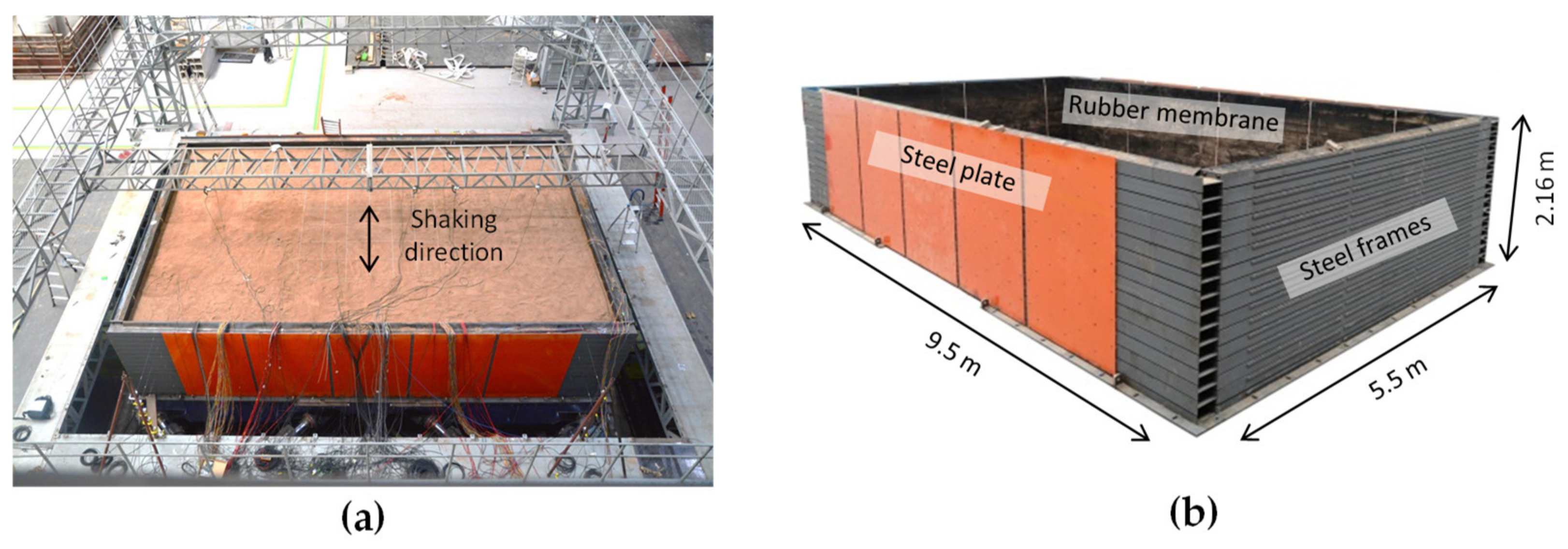
The experimental campaign was conducted at the multifunctional shaking table system of the State Key Laboratory of Disaster Reduction in Civil Engineering at Tongji University. The dimensions of the shaking table were 10.1 m × 6.1 m in its plane, and it was capable of shaking up to 140 tons of payload with a maximum acceleration of 1.5 g. The controlled frequency range was from 0.1 Hz to 50 Hz. Real seismic records, as well as synthetic motions, could be simulated. Figure 2a presents an overview of the shaking table test.
A newly designed laminar container (Figure 2b) was used in the experiments to host the model soil and structure. The laminar container consisted of 16 steel frames with effective internal dimensions of 9.5 m × 5.5 m × 2.16 m (length × width × height). The frames were stacked up through industrial ball bearings, which allowed the frames to slide smoothly in the direction of the shaking. A 5 mm thick rubber layer was covered at the inner surface of the container to reduce the vertical friction between the model soil and the box. The side of the box was connected with a restraining steel plate to prevent unfavorable torsion of the box. Based on the results of finite element (FE) pre-analysis of the laminar box, the thickness of the restraining plate was determined to be 3 mm so that the horizontal deformation of the model ground was acceptable and the dominant mode of the box (of 1.2 Hz) did not interfere with the fundamental vibration modes of the model ground. With such a configuration (Figure 2a), the shear box was only able to shear along the direction of its short side, along which the seismic motions were input in this experiment.

3. Test Design

3.1. Scaling Relations

The behavior of soil is usually related to its confining stress. Thus, using the prototype material in a model test may lead to incompatibilities between the model and the prototype due to so-called scale effects [32]. To remedy the problem of scale effects in the 1 g shaking table test, synthetic model soil was a solution, along with similitude relations derived while considering dynamic equilibrium. Such an experimental methodology was utilized in the companion paper [33], which presented a combined experimental numerical study on a single station. In the companion paper, the role of scale effects was quantified by comparing the prototype-scale results to the model-scale results. The results confirmed that the shaking table tests adopting the synthetic model soil technique could perform qualitatively similar racking deformation of the station compared to the prototype, albeit with a certain degree of difference in quantity. Providing that the schemes of shaking table testing were discussed at length in the companion paper [32], only a brief introduction is given here.
Taking into account the size and capacity of the shaking tables, a geometry scale factor S l = 1 / 25 was selected for the experiments. Synthetic model soil, a mixture of sand with sawdust which is discussed later on, offered the ability to satisfy the scaled stiffness along with the mass density. Thus, the three scale factors of shear modulus, mass density and geometry were selected to be the basic factors. The interdependent relation between the similitude ratios of these three scale factors is established as
S ρ = S G S a S l
where S ρ , S l , S G and S a are the similitude ratios of the density, geometry, shear modulus and acceleration, respectively. Providing that the similitude ratio of geometry has been determined, to maintain similitude in terms of the acceleration S a = 1 , the synthetic model soil needs to be selected appropriately to satisfy the remaining basic scaling factors of mass density and shear stiffness. In this context, the final scale factors of the geometry, density and shear modulus were set to 1/25, 1/2, and 1/50, respectively. Based on these three basic scale factors, the other scale factors could be obtained by applying the Vaschy–Buckingham π theorem. The scale factor of the quantities and the relations to derive them are summarized in Table 2.

3.2. Synthetic Model Soil

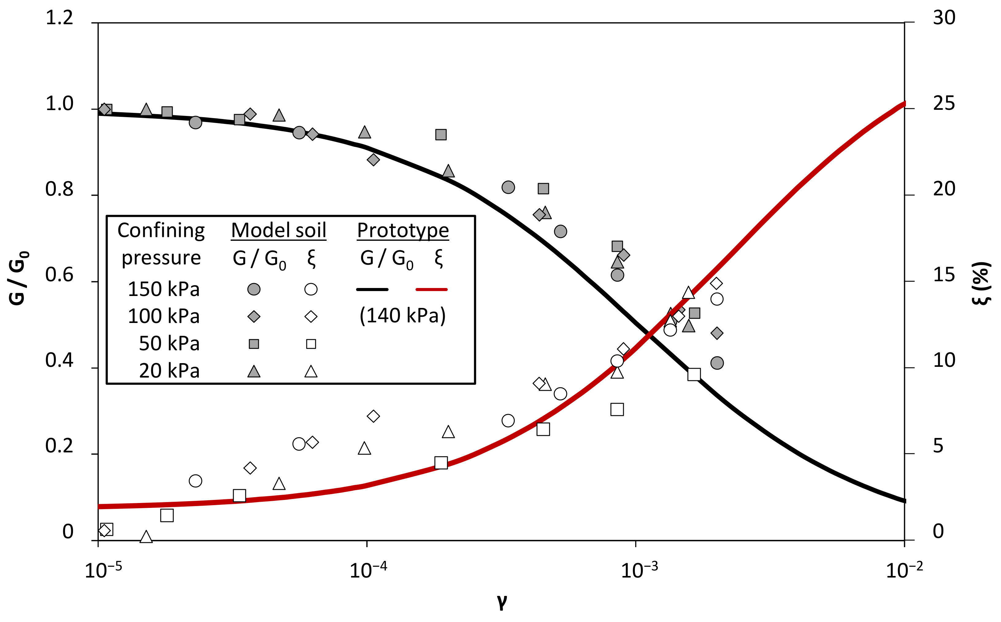
Based on the results of a series of resonant column tests, the optimum sawdust-to-sand mass ratio of 1:2.5 was determined. The density of the model soil was controlled to be 860 kg/m3 (with a relative density of D r = 90 % ) in both the laboratory test and the shaking table test. Compared with the average density of the prototype soil (1800 kg/m3), the scale factor of the density (1/2.1) was quite close to the target one in Table 2. The scale factors of the confining soil pressure were taken the same way as with the soil shear modulus, with both being 1/50. At a depth of 2 m, the maximum shear modulus of the model soil measured in the resonant column tests was 5.9 MPa—where the target modulus was 5.3 MPa—giving an error of 11%. The G / G 0 γ curves and λ γ curves of the model soil and the prototype soil, obtained from a series of resonant column tests, are compared in Figure 3.
Before the experiments, the model soil was prepared by mixing dry sand and sawdust with a blender. The physical model of the ground was constructed layer by layer. Each layer (80 mm thick) was prepared by pouring the model soil into the container. The desired density of 860 kg/m3 was achieved by controlling the weight of the soil of each layer. Then, a 2 m × 2 m steel plate was used to compact the layer by tamping until reaching the target thickness (volume). A total of 25 layers were needed to complete the physical model.

3.3. Model Structure

To model the reinforcement concrete (RC) structure of a station in proper detail, fine granular concrete was adopted as the material to produce the model structure. The concrete was a mixture of cement, sand, lime and water, with a ratio of 1:5.8:0.6:0.6 by mass. As shown in Table 3, the compressive strength and density of the concrete were 10.6 MPa and 1.86 kg/m3, respectively. Galvanized steel wires were utilized for longitudinal and transverse reinforcement. Table 4 summarizes the dimensions and compressive strength of the steel wires. The reinforcement ratios were determined by considering the resistance of the bending moment of the prototype structure, scaled down and employing the previously deduced similitude relations.
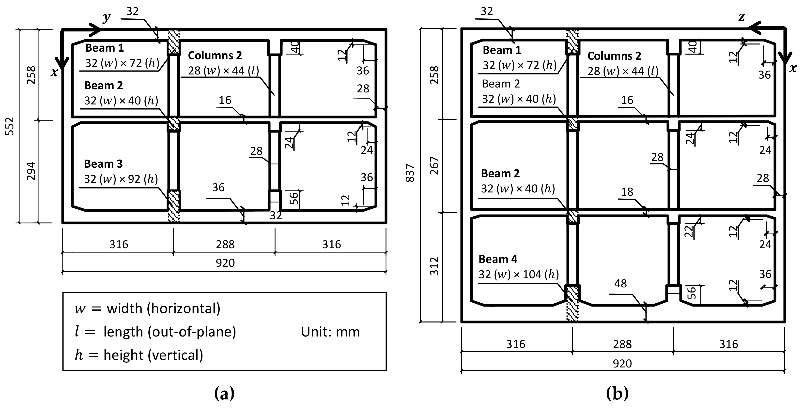
As discussed previously, two model structures were constructed in the experiments, including a model of an interchange station and a model of a single station. As depicted in Figure 4a, the cross station model contained a two-story structure and a three-story structure, both with a total length of 4.6 m. The width of the square conjunction was 920 mm, denoted as W. Each side of the two-story station out of the conjunction was 2W in length, which means only part (116 m) of the prototype interchange station (155 m) was physically modeled. This discrepancy was mainly due to the limitations on the geometry and capacity of the shaking table. However, the discrepancy was considered to be acceptable, since a preliminary numerical study on the seismic response of the prototype station showed that the length of the most-affected region of the conjunction was within two times the cross-section width [28]. A two-story single-station model, which had the same cross-section as the two-story section of the cross station, was constructed as a reference. The final model structures are shown in Figure 4. The dimensions of the cross-sections of the two-story and three-story structures are illustrated in Figure 5, in which the former one is identical in both the single station and the interchange station. The relative stiffness of the station structure corresponding to the surrounding soil was a major factor for the seismic response. According to Wang [8], the similitude ratio S F , in terms of flexibility, can be derived as follows:
S F = G m W m S p H p S m H m G p W p
where the subscripts p and m represent the prototype and the model, respectively, G is the shear modulus of the soil and W, H and S are the width, height and unit stiffness of the structure, respectively. Focusing on the two-story single-station structure, S F was calculated by 2D FE analysis, obtaining a flexibility similitude ratio S F   =   1 : 1.4 according to Equation (2). This implies that the relative stiffness of the model structure was 1.4 times greater than that of the prototype.

3.4. Instrumentation

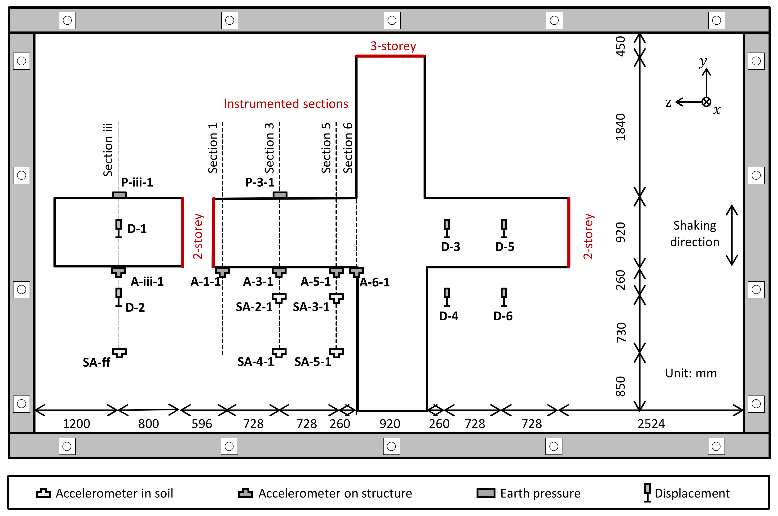
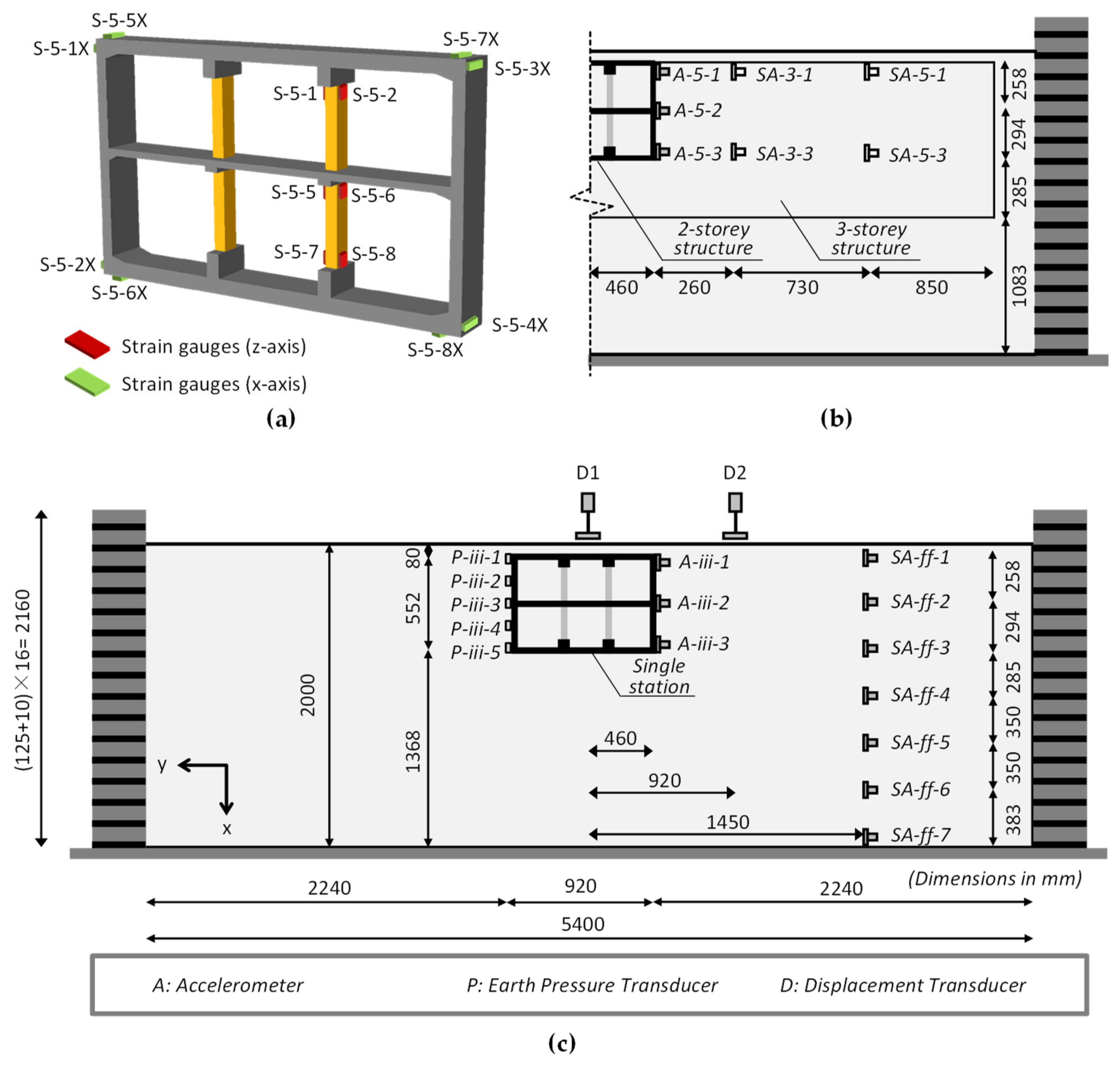
Figure 6 sketches out the plane view of the experimental layout, presenting the locations of the instruments and their key dimensions. The transverse response of the two-story section of the interchange station was focused on in this experiment. Four observational cross-sections were assigned in the two-story section. From the far end to the conjunction, the observation sections were denoted as section 1, section 3, section 5 and section 6. In terms of the single station, the middle cross-section was taken as the observation section, denoted as section iii (Figure 6). As mentioned before, the response of the two-story section was focused on. Thus, the direction of the input motion (y-direction) was defined as the transversal direction, while the z-direction was defined as the longitudinal direction.
The two model structures—the interchange station and the single station—were both instrumented by a number of accelerometers (Setra 141), strain gauges (PFL-10-11), earth pressure sensors (CYY9-30), inclinometers (HVS120T) and displacement transducers (DP-500F). The layouts of the sensors in the typical instrumented cross-section plane are illustrated in Figure 7. As shown in Figure 7a, the strain gauges were installed on the two-story section of the interchange station in both the transversal and longitudinal directions. The length of the strain gauges selected was 10 mm, which was capable of measuring the strain on a rather rough surface of the concrete member. Figure 7b,c illustrates the representative cross-section of the interchange station (section 5) and the single station (section iii), respectively. The accelerometers were installed at the heights of the three slabs of the two-story structure to record the accelerations on the structure (denoted as A-x-1–A-x-3). Seven accelerometers (SA-ff-1–SA-ff-7) were installed 990 mm away from the sidewall of the single two-story structure, aiming to measure the free field response. Near the interchange station structure, there were four arrays of accelerometers installed in the soil, each one of them containing two accelerometers.

3.5. Input Motions

The input motions were 10 cycles sinusoidal excitations of the peak acceleration, equal to 0.1 g. The dominant frequencies ( f E ) of the sinusoidal excitations were 2 Hz, 4 Hz, 8 Hz and 10 Hz, with the purpose of enveloping the fundamental frequency of the ground (around 7.5 Hz). Sinusoidal excitations allowed the manifestation of the dynamic responses of the models at given frequencies. Furthermore, by taking advantage of their well-defended characteristic spectrum, it was more convenient and convincing to decide the bandwidth for filtering out the spurious, very low frequency components and high-frequency electrical noise. The time history of the achieved excitation with a dominant frequency of 10 Hz is illustrated in Figure 8, along with the elastic response spectra of the four input sinusoidal excitations.
Before the successive sinusoidal cases, the white noise motion was applied to investigate the inherent dynamic characteristics of the model. The amplitude of the white noise motion was set as low as possible to a value of 0.02 g, attempting to carry out a so-called zero test [34], in which the model was subjected to a very low deformation level. In this way, the initial elastic dynamic characteristics associated with the small strain shear modulus could be estimated from the transfer functions. After the harmonic cases, the same white noise motion was tested to verify the consistency of the dynamic characteristics of the model. The sequence of the input base motions is listed in Table 4.

4. Results of the Shaking Table Tests

The characteristic results are presented and discussed, highlighting the key aspects of the soil–structure response of the cross interchange station. Unless otherwise stated, the results are shown at the model scale.

4.1. Horizontal Acceleration of the Soil

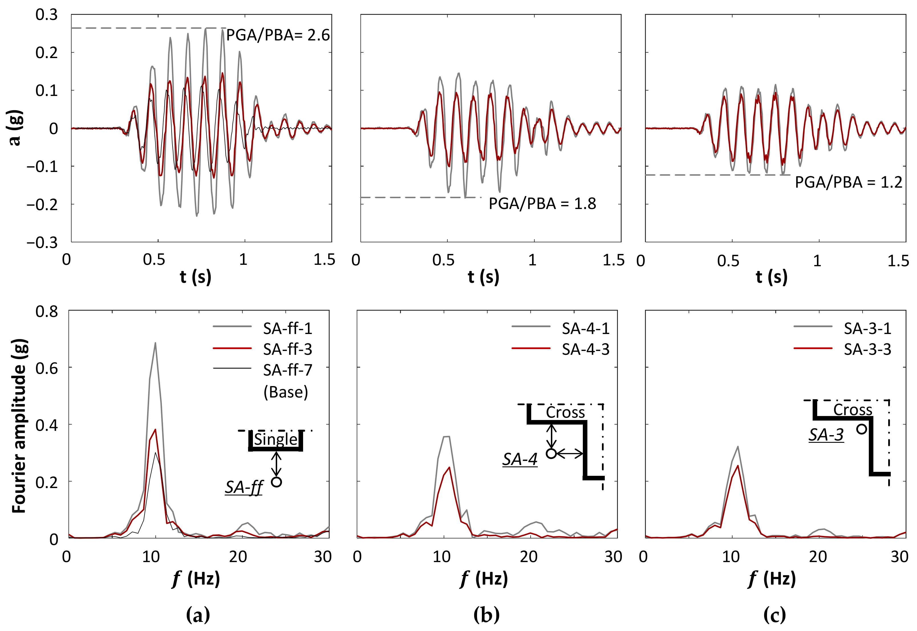
The representative time histories recorded by the accelerometers in three soil columns are shown in Figure 9 for the Sin-10Hz case. Figure 9a compares the free field acceleration time histories at the height of top slab (SA-ff-1) and the bottom slab (SA-ff-3) of the two-story structure, with the input acceleration recorded at the base (SA-ff-7) along with their Fourier spectrum. The SA-ff array was 1.1W (W = 920 mm, the width of the cross-section) away from the sidewall of the single station. It can be seen that the acceleration of SA-ff-1 and SA-ff-3 was clearly amplified from the base during the propagation of seismic motion, mainly due to the amplification of the dominant frequency region (7–12 Hz) of the input motion. The peak ground acceleration (PGA) was 2.6 times higher than the peak base acceleration (PBA). In the meantime, Figure 9b shows the two accelerations corresponding to the height of the top and bottom slab in the acceleration array of SA-3, which was 1.1W away from the interchange station. Smaller amplification was found for both heights, indicating that the existence of the interchange station de-amplified the near-structure soil acceleration from the free field. More pronounced de-amplification effects on the free field response are shown in Figure 9c. It compares the accelerations recorded in the acceleration array SA-3, which was only 0.3W away from the interchange station. Such effects were also found in the rest of the input sinusoidal motions, as will be presented in Section 5.2.

4.2. Horizontal Acceleration of Structure

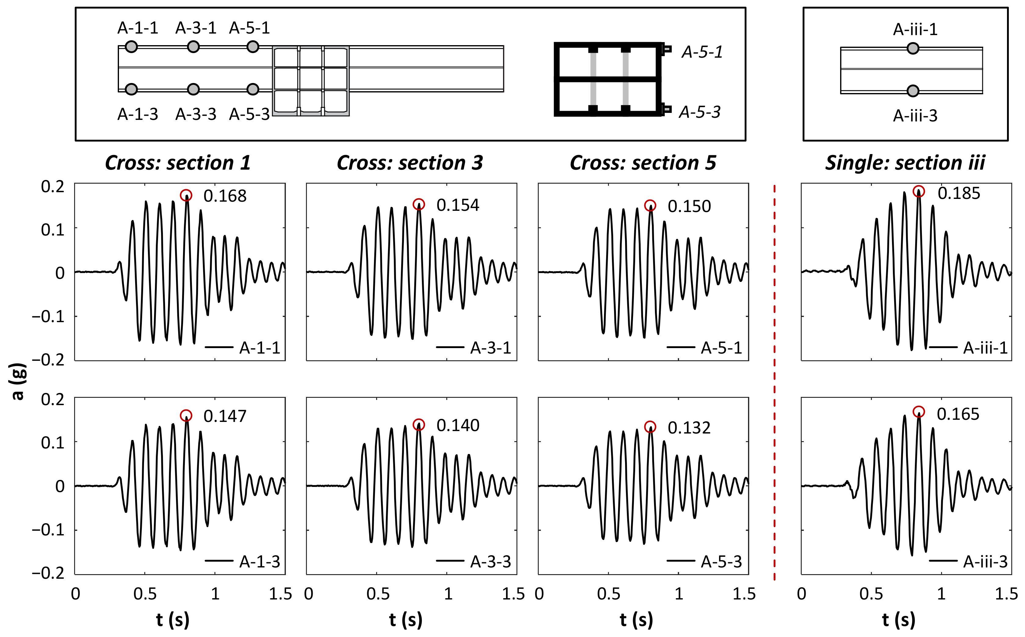
Figure 10 shows the time histories of the horizontal (y-direction) acceleration recorded at the top and bottom of the sidewall in section 1, section 3 and section 5 of the interchange station and those in section iii of the single station during the Sin-10 Hz case. In both the interchange station and the single station, the peak acceleration (PA) values at the top of the sidewall were greater than those at the bottom of the sidewall in all sections, indicating that both stations were subjected to transversal deformation. When comparing the acceleration responses recorded in different cross-sections, it was found that the PAs recorded in section 1 (further from the junction) were higher than those in section 5 (closer to the junction). Such differences were manifestations of the discrepant responses of the two-story structure and the conjunction, even under uniform seismic loading. It is understandable to find such a discrepant response because under the y-direction seismic shaking, the two-story section of the interchange station was subjected to transversal motions, while the three-story section in the perpendicular direction was subjected to longitudinal shaking. Due to their different features (e.g., aspect ratio (height/width), slenderness ratio (length/width) and relative stiffness of the structure), these two sections of the interchange station tended to display inconsistent movement behavior, save for the connection of the junction. Predictably, the restriction of the conjunction could yield strain concentrations near the connection part, as presented in the following.

4.3. Dynamic Longitudinal Strains of the Cross Station

The time histories and peak tensile values of the dynamic longitudinal strains recorded at interchange station in section 3, section 5 and section 6 are presented in Figure 11. To eliminate the spurious frequency components caused by the sensor [35], the presented strain data were processed by a band-pass filter using a zero-phase, eighth-order Butterworth filter. The applied filter introduced no phase shifts. The characteristics of the filter for each case are summarized in Table 5. The bandwidth was determined to be wide enough to conserve the main frequency characteristics of the strain response.
Figure 11a,b compares the time histories of the dynamic, incremental longitudinal strains in section 3, section 5 and section 6 during the sinusoidal case with a frequency of 10 Hz. In general, the time histories of the dynamic strain pairs recorded at the two sides of the station were found to be 180 degrees out of phase, indicating the deflection of the two-story structure along the longitudinal axis during transversal seismic excitation. As expected, the dynamic increment of the longitudinal strains was conspicuously higher in section 6, which decreased in section 5, section 3 and also section 1 (which was not shown here). Figure 11c extracted the maximum tensile strains at different locations of the three cross-sections from the time histories. In general, the strain gauges in section 6 picked up larger strains compared with the other sections at their corresponding locations. As an example, the maximum tensile strain of S6-2X was 12.4 μϵ, while it was 4.5 μϵ and 4.4 μϵ in section 5 and section 3, respectively. In section 6, the peak dynamic longitudinal strains recorded at the elevation of the bottom slab were generally higher than those recorded at the elevation of the top slab.

4.4. Dynamic Strains of the Columns

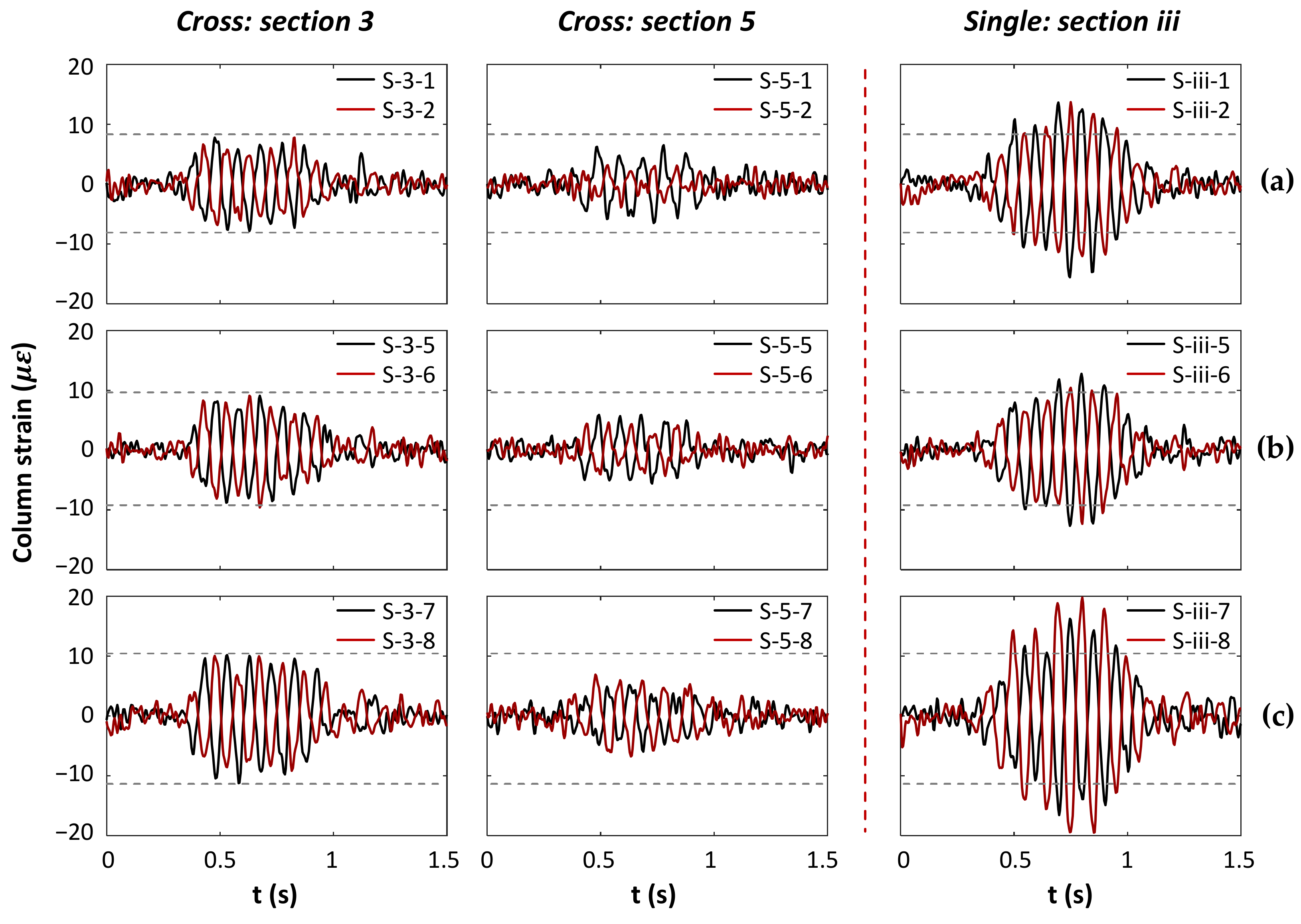
Before the experiments, the authors [28] carried out a series of numerical analyses, predicting that the deformation pattern of the interchange station contained deflection along the longitudinal axis and story drifts in the cross-sectional plane during the transversal earthquake. The dynamic bending strain of the column was determined by, and therefore an indicator of, the story drifts. Section 3 and section 5 of the interchange station, together with section iii of the single station, were deployed with transversal strain gauges measuring the bending strain of the columns. As in the case of Sin-10Hz, the time histories of the incremental bending strain pairs recorded on the top of the upper story’s right column for these three cross-sections were compared in Figure 12a. Similar comparisons were made for the top and base of the lower story’s central column, which are presented in Figure 12b,c, respectively. All the strain pairs showed a 180 degree out-of-phase response, indicating the bending reaction of the columns. It was found that the central columns of the interchange station in both section 5 and section 3 recorded lower dynamic bending strains compared with the corresponding strains of the single station. This was mainly because of the restriction of conjunction on the deformation of the cross-section in the interchange station. Between the two cross-sections in the interchange station, section 3 was the one further from the conjunction and recorded a higher dynamic bending strain compared with section 5. Such a difference contributed to the decreasing restraint effects of the conjunction with the increasing distance. In both the interchange and the single station, the bending strains of the column were observed to be slightly higher on the base of the lower-story column.

5. Interpretation and Discussion

5.1. Frequency Response of the Model

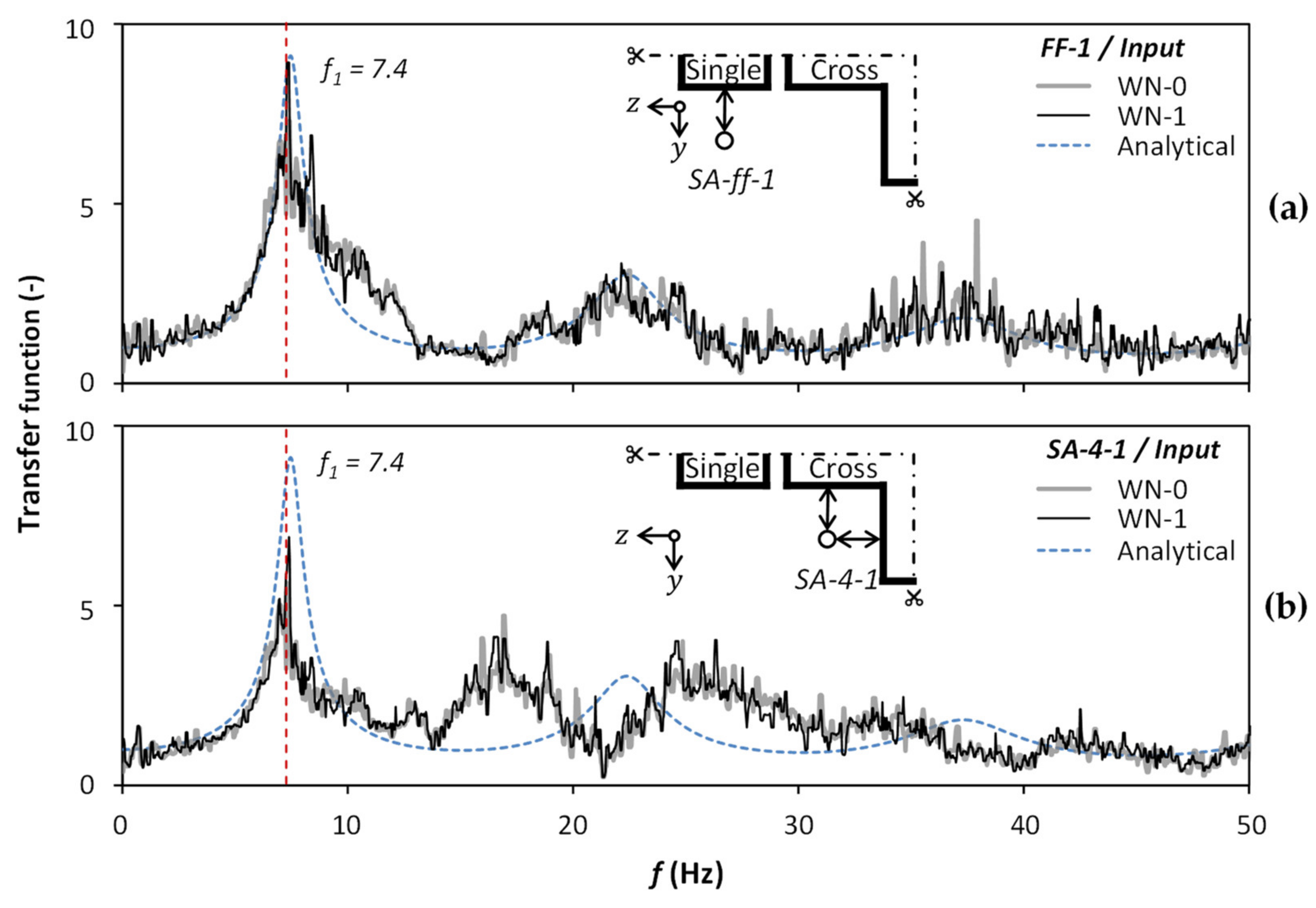
To evaluate the effect of the interchange station on soil response, a transfer function (TF) was used to obtain the Fourier amplitude ratio of the acceleration response at the ground surface as a function of the frequency of the input motion at the base. For a free field homogeneous damped soil on a rigid base, the analytical formulation of the transfer function can be expressed as [36]
TF ω = 1 / cos 2 ω H V s + ξ ω H V s 2  
where ω is the frequency, ξ is the damping ratio and H and V s are the height and shear wave velocity of the soil, respectively. The analytical solution is based on the assumption of the viscoelastic behavior of the soil. Thus, low-intensity white noise (PGA = 0.02 g) was adopted in order to minimize the effect of nonlinear degradation of the shear modulus of the model soil. Figure 13a compares the transfer function of the model ground recorded in the cases of WN-0 and WN-3, along with the analytical solution at the SA-ff array. Similar comparisons are shown in Figure 13b for the SA-4 array out of the cross interchange station.
The good comparison of the experimental TF in the two white noise cases, WN-0 and WN-1, confirmed the consistency of the dynamic characteristics of the model ground throughout the tests, indicating the repeatability of the test results. The fundamental frequencies ( f 1 ) of the ground at both arrays were observed to be 7.4 Hz. The analytical fitting was then calculated through Equation (3), associated with the target parameters of the fundamental frequencies f 1 = 7.4 Hz and the damping ratio ξ = 7 % . As shown in Figure 13a, the comparison between the analytical TF and experimental TF recorded from the SA-ff array was generally good, in terms of the first three harmonic frequencies (denoted in order as f 1 , f 2 and f 3 , respectively). It confirmed that the soil response recorded at the SA-ff array (out of the single station) was close to the analytical assumption as a free field condition. The slight discrepancy around the frequency of 10 Hz could apply to the influence of the single station structure [20]. In the SA-4 array, which was 1.1W from the interchange station structure (Figure 13b), the fundamental frequency followed the far field soil. However, for the second and third fundamental frequencies ( f 2 = 16.9 Hz and f 3 = 24.7 Hz), the TF of the SA-4 array differed from the analytical solution, which indicated the influence of the underground structures on the high-order frequency of the free field response. It should be noted that both the SA-ff and SA-4 arrays were 1.1W away from the two-story structure. However, SA-4 was further affected by the conjunction and the three-story section, which led to spatial effects of the interchange station on the soil.

5.2. Spatial Effects of the Interchange Station on the Ground Response

The effects of the single underground structure on the ground acceleration were revealed in a number of experimental and numerical studies [37,38]. The amplification pattern of the soil near the underground structure depends on several factors, such as the width, depth and relative stiffness of the underground structure. Due to the uniform cross-section, it is understandable that a single tunnel affects the amplification pattern consistently along the longitudinal axis when subjected to transversal excitation. However, in the case of the interchange station, the conjunction brings an abrupt change of the cross-section and, as a result, change to the above-mentioned factors could change the amplification pattern from two-dimensional (horizontal and vertical) to three-dimensional (spatial).
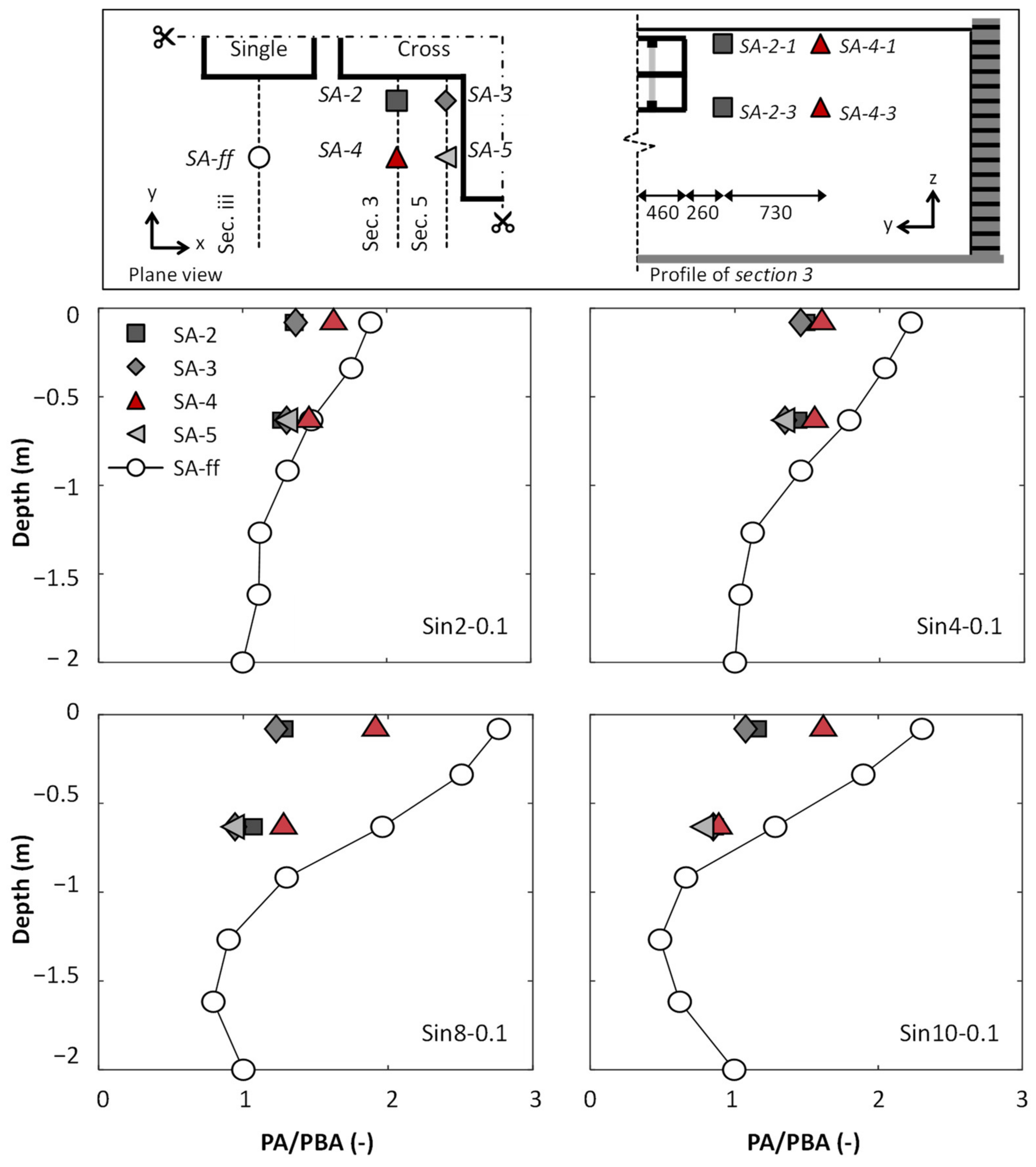
Figure 14 compares the amplification ratios from the peak acceleration (PA) to the peak base acceleration (PBA) versus the depth along the SA-2~SA-5 and SA-ff soil columns during all of the tested sinusoidal motions. The location of the acceleration arrays in the plane view and the cross-section view is also illustrated in Figure 14. The acceleration from SA-5-1 is not shown in the figure due to damage during the preparation of the model ground. The amplification pattern of the PGA was prominent in the SA-ff soil column. Among the sinusoidal excitations, the largest amplification ratio—to the order of 2.7—was observed for the one with the frequency of 8 Hz. This was because the fundamental frequencies of the ground were around 7.4 Hz, and the resonance-like phenomenon may have been induced under the Sin-8Hz seismic motion. Overall, SA-2~SA-5 recorded lower PAs at the same depth compared with the SA-ff array, indicating the de-amplification effects of the interchange station on the free field response. A recent numerical study [26] also predicted a similar de-amplification phenomenon and suggested that the reason for this was that the interchange station, to some extent, blocked the propagation of seismic waves. With regard to the four arrays near the interchange station (SA-2~SA-5), the recorded PAs differed in the function of their elevations and relative locations to the cross station structure, indicating the spatial effects of the interchange station on the soil response. Among them, the SA-4 array recorded a more significant amplification and relatively higher PA compared with SA-2 and SA-3. The profile of the soil acceleration in SA-4 was more alike to the free field soil (SA-ff) because SA-4 was the most distant array from the interchange station in both directions in the plane. Correspondingly, the nearest array to the interchange station, SA-3, gave the lowest PGAs and a much lower amplification of soil acceleration from SA-3-3 to SA-3-1. The lower amplification might be attributed to the constraint effects of the stiff conjunction on the near-structure soil. Special consideration needs to be paid to such spatial effects, for example, when considering the interchange station and soil building dynamic interaction in the urban environment.

5.3. Bending Moment of the Central Columns

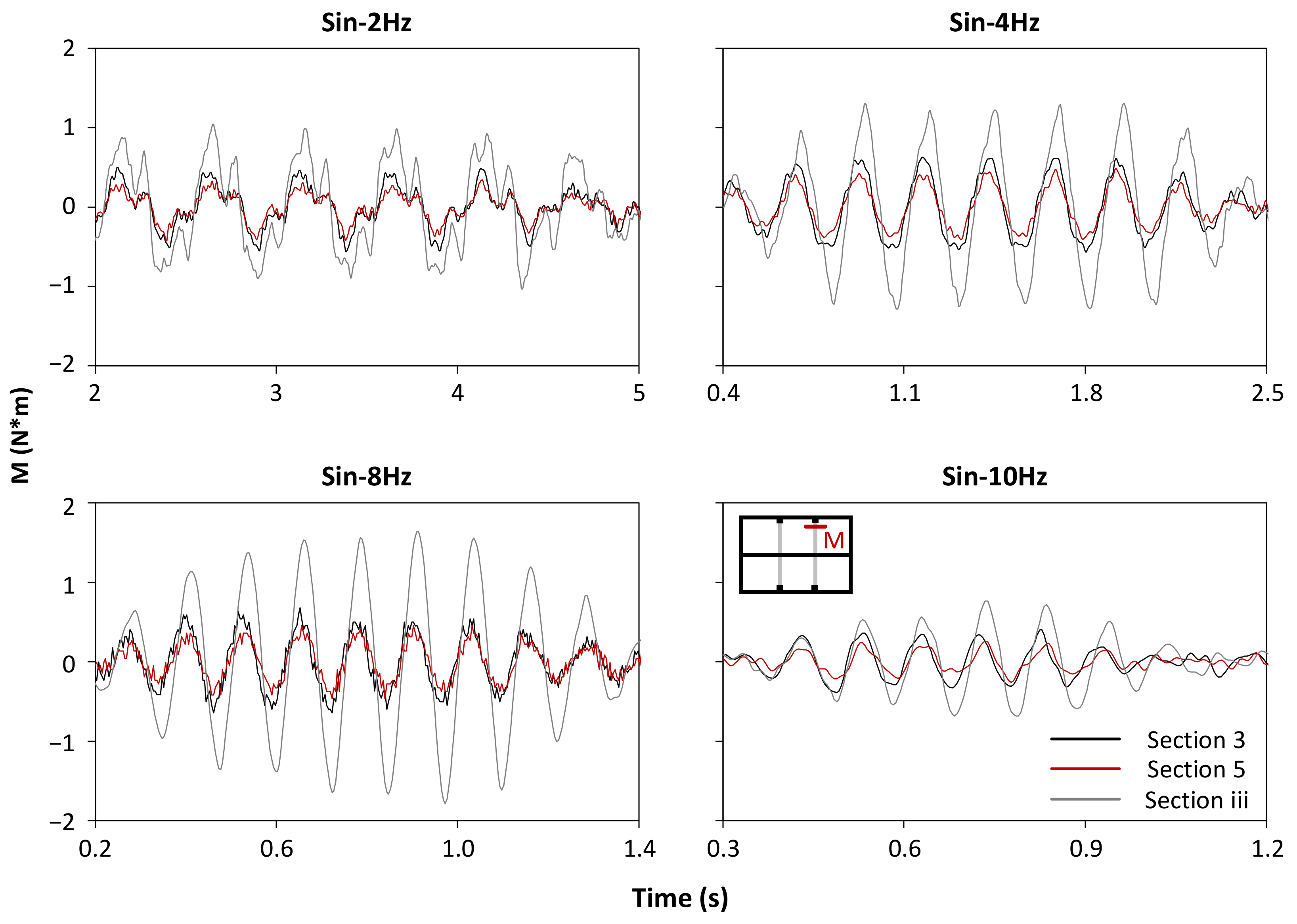
Figure 15 compares the bending moment histories of the upper column at the top end in section 3 and section 5 of the interchange station with section iii of the single station under the four sinusoidal excitations. The bending moment was derived from the strain pair installed at two sides of the top end of the column on the upper floor. Among the four cases, the maximum moment occurred in the case of Sin-8Hz for both stations, which confirmed the general resonance knowledge. Typically, in all of the four cases, the bending moment of the column in section 3 of the interchange station was lower than that in section iii of the single station by about 60–75%. This was mainly because of the restriction of cross-section deformation caused by the conjunction with the sidewall of three-story section. In the interchange station, the bending moment of the column in section 5 was about 25–35% lower than that in section 3, which attributed to the increased constraint effect close to the conjunction.

6. Summary and Conclusions

Prior numerical and analytical studies have documented the necessity of addressing the joint effect on seismic performance for underground structures with abrupt stiffness changes. However, the above models have yet to be validated by experiments due to the lack of laboratory data. As part of the ongoing Shanghai Metro-funded research project, aiming at a better understanding of the seismic behavior of the cross interchange station and developing rational design methods, the presented paper focused on the large-scale shaking table study. A series of large-scale (1 g) shaking table tests were conducted at Tongji University, using synthetic model soil (a mixture of sawdust and dry sand) and granular concrete with steel wires to model the soil–structure system. An experimental comparative study of the interchange station was carried out in reference to a single station under sinusoidal seismic excitations. The key conclusions can be summarized as follows:
  • The horizontal accelerations recorded in the four soil arrays near the interchange station were found to vary based on their relative locations from the structure, indicating the spatial effects of the interchange station on the near-structure soil;
  • It was found to be consistent in the interchange station and the single station that the horizontal acceleration recorded on the elevation of the top slab was higher than that of the bottom slab. Though subjected to uniform transverse excitations, the conjunction and the two-story section of the interchange station responded differently, as revealed by the horizontal acceleration data;
  • The time histories of the dynamic longitudinal strain pairs recorded at the two sides of the cross-section were found to be 180 degrees out of phase. This indicated the deflection of the longitudinal axis of the two-story section under transversal motions, which was caused by the discrepant response. The longitudinal strain was distinctly raised near the conjunction, where special attention should be paid to seismic design;
  • The bending moment of the column in the two-story part of the interchange station was affected by its rigid conjunction to the three-story part. The columns recorded a greater bending moment in section 5, which was further from the conjunction, compared with the closer one (section 3). The presence of the conjunction also induced a lower column moment in the interchange station compared with those in the single station.
This paper provides experimental insights into the seismic response of a typical cross interchange station. However, a number of factors could affect the station–conjunction-soil interaction, including relative soil–station stiffness, soil–structure interface behaviors and input motions. After being calibrated against the experiments, further numerical analysis is needed to shed light on the sophisticated response of the interchange station. Numerical simulation in accord with the experiment conditions, as well as a comprehensive investigation, will be presented in another upcoming paper.

Author Contributions

Conceptualization, S.G.; methodology, Y.Y. and W.W.; software, W.W.; validation, Y.Y.; formal analysis, W.W.; investigation, W.W.; resources, S.G., W.D. and Y.Y.; data curation, W.W.; writing—original draft preparation, W.W.; writing—review and editing, Y.Y., W.D. and S.G.; visualization, W.W.; supervision, S.G., Y.Y. and W.D.; project administration, Y.Y.; funding acquisition, S.G., Y.Y. and W.D. All authors have read and agreed to the published version of the manuscript.

Funding

The authors express their gratitude for the financial support from the National Natural Science Foundation of China (51478343 & 51778487& 52061135112) and the Shanghai Metro Research Project (JS-KY17R031-6).

Institutional Review Board Statement

Not applicable.

Informed Consent Statement

Not applicable.

Data Availability Statement

The data that support the findings of this study are available from the Shanghai Metro Group. Restrictions apply to the availability of these data, which were used under license for this study. Data are available from the corresponding authors with the permission of the Shanghai Metro Group.

Acknowledgments

The second author would like to acknowledge the China Scholarship Council, China (CSC201806260187) for providing a scholarship for this work.

Conflicts of Interest

The authors declare no conflict of interest.

References

  1. Iida, H.; Hiroto, T.; Yoshida, N.; Iwafuji, M. Damage to Daikai subway station. Soils Found. 1996, 36, 283–300. [Google Scholar] [CrossRef]
  2. An, X.; Shawky, A.A.; Maekawa, K. The collapse mechanism of a subway station during the Great Hanshin earthquake. Cement. Concrete. Comp. 1997, 19, 241–257. [Google Scholar] [CrossRef]
  3. Menkiti, C.O.; Sanders, P.; Barrr, J.; Mair, R.J.; Cilingir, M.; James, S. Effects of the 12th November 1999 Duzce Earthquake on Stretch 2 of the Gumusova-Gerede Motorway in Turkey. In Proceedings of the International Road Federation 14th World Road Congress, Paris, France, 11–15 June 2001; pp. 11–15. [Google Scholar]
  4. Kontoe, S.; Zdravkovic, L.; Potts, D.M.; Menkiti, C.O. Case study on seismic tunnel response. Can. Geotech. J. 2008, 45, 1743–1764. [Google Scholar] [CrossRef] [Green Version]
  5. Yu, H.; Chen, J.; Bobet, A.; Yuan, Y. Damage observation and assessment of the Longxi tunnel during the Wenchuan earthquake. Tunn. Undergr. Space Technol. 2016, 54, 102–116. [Google Scholar] [CrossRef]
  6. Hashash, Y.; Hook, J.; Schmidt, B.; Yao, J. Seismic design and analysis of underground structures. Tunn. Undergr. Space Technol. 2001, 16, 247–293. [Google Scholar] [CrossRef]
  7. St John, C.M.; Zahrah, T.F. Aseismic design of underground structures. Tunn. Undergr. Space Technol. 1987, 2, 165–197. [Google Scholar] [CrossRef]
  8. Wang, J.N. Racking effect on rectangular tunnels. In Seismic Design of Tunnels: A State-of-the-Art Approach; Parsons, Brinckerhoff, Quade and Douglas Inc.: New York, NY, USA, 1993. [Google Scholar]
  9. Penzien, J. Seismically induced racking of tunnel linings. Earthq. Eng. Struct. Dyn. 2000, 29, 683–691. [Google Scholar] [CrossRef]
  10. Huo, H.; Bobet, A.; Fernández, G.; Ramírez, J. Analytical solution for deep rectangular structures subjected to far-field shear stresses. Tunn. Undergr. Space Technol. 2006, 21, 613–625. [Google Scholar] [CrossRef]
  11. Akira, T. A study on seismic analysis methods in the cross section of underground structures using static finite element method. Earthq. Eng. Struct. Dyn. 2005, 22, 41s–54s. [Google Scholar]
  12. Gil, L.M.; Hernandez, E.; Fuente, P.D. Simplified transverse seismic analysis of buried structures. Soil Dyn. Earthq. Eng. 2001, 21, 735–740. [Google Scholar] [CrossRef]
  13. International Organization for Standardization (ISO). ISO 23469: Bases for design of structures—Seismic actions for designing geotechnical works. In International Standard ISO TC98/SC3/WG10; International Organization for Standardization: Geneva, Switzerland, 2005. [Google Scholar]
  14. Huo, H.; Bobet, A.; Fernández, G.; Ramírez, J. Load transfer mechanisms between underground structure and surrounding ground: Evaluation of the failure of the Daikai station. J. Geotech. Geoenviron. Eng. 2005, 131, 1522–1533. [Google Scholar] [CrossRef]
  15. Yu, Y.; Yuan, Y.; Qiao, Z.; Gu, Y.; Yang, Z.; Li, X. Seismic analysis of a long tunnel based on multi-scale method. Eng. Struct. 2013, 49, 572–587. [Google Scholar] [CrossRef]
  16. Anastasopoulos, I.; Gerolymos, N.; Drosos, V.; Kourkoulis, R.; Georgarakos, T.; Gazetas, G. Nonlinear response of deep immersed tunnel to strong seismic shaking. J. Geotech. Geoenviron. Eng. 2007, 133, 1067–1090. [Google Scholar] [CrossRef]
  17. Bobet, A.; Fernandez, G.; Huo, H.; Ramirez, J. A practical iterative procedure to estimate seismic-induced deformations of shallow rectangular structures. Can. Geotech. J. 2008, 45, 923–938. [Google Scholar] [CrossRef]
  18. Tsinidis, G.; Pitilakis, K.; Madabhushi, G.; Heron, C. Dynamic response of flexible square tunnels: Centrifuge testing and validation of existing design methodologies. Geotechnique 2015, 65, 401–417. [Google Scholar] [CrossRef] [Green Version]
  19. Bilotta, E.; Lanzano, G.; Madabhushi, S.P.G.; Silvestri, F. A numerical round robin on tunnels under seismic actions. Acta Geotech. 2014, 9, 563–579. [Google Scholar] [CrossRef]
  20. Zhang, Z.; Bilotta, E.; Yuan, Y.; Yu, H.; Zhao, H. Experimental assessment of the effect of vertical earthquake motion on underground metro station. Appl. Sci. 2019, 9, 5182. [Google Scholar] [CrossRef] [Green Version]
  21. Zhuang, H.; Chen, G.; Hu, Z.; Qi, C. Influence of soil liquefaction on the seismic response of a subway station in model tests. Bull. Eng. Geol. Environ. 2016, 75, 1169–1182. [Google Scholar] [CrossRef]
  22. Tao, L.; Ding, P.; Shi, C.; Wu, X.; Wu, S.; Li, S. Shaking table test on seismic response characteristics of prefabricated subway station structure. Tunn. Undergr. Space Technol. 2019, 91, 102994. [Google Scholar] [CrossRef]
  23. Miao, Y.; Yao, E.; Ruan, B.; Zhuang, H. Seismic response of shield tunnel subjected to spatially varying earthquake ground motions. Tunn. Undergr. Space Technol. 2018, 77, 216–226. [Google Scholar] [CrossRef]
  24. Liu, Z.; Chen, Z.; Liang, S.; Li, C. Isolation mechanism of a subway station structure with flexible devices at column ends obtained in shaking-table tests. Tunn. Undergr. Space Technol. 2020, 98, 103328. [Google Scholar] [CrossRef]
  25. Yuan, Y.; Yang, Y.; Zhang, S.; Yu, H.; Sun, J. A benchmark 1 g shaking table test of shallow segmental mini-tunnel in sand. Bull. Earthq. Eng. 2020, 18, 5383–5412. [Google Scholar] [CrossRef]
  26. Chen, S.; Zhuang, H.; Quan, D.; Yuan, J.; Zhao, K.; Ruan, B. Shaking table test on the seismic response of large-scale subway station in a loess site: A case study. Soil Dyn. Earthq. Eng. 2019, 123, 173–184. [Google Scholar] [CrossRef]
  27. Yuan, L.; Jiang, X. Influence of irregular structure of subway transfer station on its seismic responses. Earthq. Eng. Eng. Vib. 2011, 31, 74–79. (In Chinese) [Google Scholar]
  28. Wu, W.; Ge, S.; Ding, W.; Yuan, Y. Seismic Response of a Cross Transfer Subway Station in Soft Soil Subjected to Different Ground Motion Directions. In Proceedings of the GeoShanghai International Conference, Singapore, 6 May 2018; pp. 27–35. [Google Scholar]
  29. Wang, G.; Yu, M.; Yuan, M.; Li, K. Seismic response analysis of cross metro transfer station structure. Chin. J. Geotech. Eng. 2019, 41, 1227–1234. (In Chinese) [Google Scholar]
  30. Yu, Z.; Zhang, H. Seismic characteristics and design method for cross transfer subway stations. J. Southeast Univ. 2019, 49, 1011–1018. (In Chinese) [Google Scholar]
  31. Stamos, A.A.; Beskos, D.E. Dynamic analysis of large 3-D underground structures by the bem. Earthq. Eng. Struct. Dyn. 1995, 24, 917–934. [Google Scholar] [CrossRef]
  32. Wood, D.M.; Crewe, A.; Taylor, C. Shaking table testing of geotechnical models. Int. J. Phys. Model. Geotech. 2002, 2, 1–13. [Google Scholar] [CrossRef]
  33. Wu, W.; Ge, S.; Yuan, Y.; Ding, W.; Anastasopoulos, I. Seismic response of subway station in soft soil: Shaking table testing versus numerical analysis. Tunn. Undergr. Space Technol. 2020, 100, 103389. [Google Scholar] [CrossRef]
  34. Brennan, A.J.; Thusyanthan, N.I.; Madabhushi, S.P.G. Evaluation of shear modulus and damping in dynamic centrifuge tests. J. Geotech. Geoenviron. 2005, 131, 1488–1497. [Google Scholar] [CrossRef]
  35. Trifunac, M.D.; Lee, V.W. A note on the accuracy of computed ground displacements from strong-motion accelerograms. Bull. Seismol. Soc. Am. 1974, 64, 1209–1219. [Google Scholar]
  36. Kramer, S.L. Wave propagation. In Geotechnical Earthquake Engineering; Pearson Education India: Delhi, India, 1996. [Google Scholar]
  37. Rabeti Moghadam, M.; Baziar, M.H. Seismic ground motion amplification pattern induced by a subway tunnel: Shaking table testing and numerical simulation. Soil Dyn. Earthq. Eng. 2016, 83, 81–97. [Google Scholar] [CrossRef]
  38. Bilotta, E.; Lanzano, G.; Silvestri, F.; Russo, G.; Silvestri, F.; Madabhushi, G. Seismic analyses of shallow tunnels by dynamic centrifuge tests and finite elements. In Proceedings of the 17th International Conference on Soil Mechanics and Geotechnical Engineering, Alexandrìa, Egypt, 5–9 December 2009; pp. 474–477. [Google Scholar]
Figure 1. Prototype. (a) Location of the prototype station in the metro route map of Shanghai, China. (b) 3D model of the prototype station with the key dimensions (unit: m).
Applsci 11 01551 g001
Figure 2. Laminar box used for the shaking table tests. (a) Overview of the soil container installed on the multifunctional shaking table of Tongji University and (b) its key dimensions.
Applsci 11 01551 g002
Figure 3. Comparison of the resonant column test results of the prototype (mud clay) and the synthetic model soil under confining pressures.
Applsci 11 01551 g003
Figure 4. Final model structures of (a) the cross interchange station and (b) the single station in mm.
Applsci 11 01551 g004
Figure 5. Cross-sections of (a) a two-story section and (b) a three-story section in mm.
Applsci 11 01551 g005
Figure 6. Layout of the experiment in the plane view, showing key dimensions and instrumentation with measurements expressed in mm.
Applsci 11 01551 g006
Figure 7. Instrumentations of (a) the strain gauges on the structure, (b) the sensors in section 3 and (c) the sensors in section iii, with units expressed in mm.
Applsci 11 01551 g007
Figure 8. Seismic excitations used in the shaking table tests, with a peak ground acceleration (PGA) of 0.1 g.
Applsci 11 01551 g008
Figure 9. Time histories of the soil accelerations recorded during sinusoidal excitation, with a dominant frequency of 10 Hz in (a) the SA-ff array at the elevation of the base, bottom and top slab of the two-story structure, (b) the SA-4 array and (c) the SA-3 array at the elevation of the bottom and top slab of the two-story structure.
Applsci 11 01551 g009
Figure 10. Transverse acceleration response recorded in section iii of the single station and section 1, section 3 and section 5 of the interchange station during the sinusoidal excitation, with a dominant frequency of 10 Hz. The locations of the accelerometers are also illustrated.
Applsci 11 01551 g010
Figure 11. Dynamic longitudinal strain along the two-story structure, recorded on the outside of the sidewall in section 1, section 3 and section 5 at the elevation of (a) the top and (b) the bottom of the sidewall. (c) Observed maximum tension strains during the sinusoidal excitation with a dominant frequency of 10 Hz.
Applsci 11 01551 g011
Figure 12. Comparison of dynamic strain recorded on columns in the two-story part of the interchange station (section 3 and section 5) and the single station (section iii) at (a) the top end of the upper column, (b) the top end of the lower column and (c) the bottom end of the lower column during the sinusoidal excitation with a dominant frequency of 10 Hz.
Applsci 11 01551 g012
Figure 13. Comparison of the transfer function during the white noise motions before and after tests, along with the analytical results with 7% damping (a) in the accelerometer array out of the single station (SA-ff) and (b) in the accelerometer array out of cross interchange station (SA-4).
Applsci 11 01551 g013
Figure 14. Amplification ratio of the peak acceleration (PA) to the peak base acceleration (PBA) as a function of the depth for the accelerometer arrays SA-2~SA-4 and SA-ff during all the tested sinusoidal motions, along with illustrations of the accelerometer locations.
Applsci 11 01551 g014
Figure 15. Time history of the bending moment at the top end of the column of the upper story, derived from the strain pair records: a comparison between the single station and different sections of interchange station in the case of four sine sweep cases.
Applsci 11 01551 g015
Table 1. Prototype soil profile and key soil properties of the encountered layers.
No.SoilDepth (m) V s   ( m / s ) γ 0   ( kN / m 3 ) c   ( kPa ) φ   ( ° )
1Fill1.912517.3--
2Silty clay3.512818.5--
3Silty clay9.512517.1431
4Mud clay17.613716.6328
5Clay23.818917.4225
6Silty clay30.923519.4526
7Sandy silt42.825518.9733
8Silt5032218.9--
Table 2. Similitude relations and scale factors.
QuantitySimilarity RelationsScale Factor
Displacement ( u ) S l 1/25
Density (ρ) S ρ 1/2
Shear modulus ( G s ) S G 1/50
Acceleration (α) S G / S l S ρ 1
Time ( t ) S l / S a 0.5     1/5
Velocity (V) S a S l 0.5 1/5
Shear wave velocity ( V s ) S G / S ρ 0.5 1/5
Frequency, dynamic ( f ) S l / S a 0.5 5
Natural frequency ( N F ) S G / S ρ 0.5 / S l 5
Force ( F ) S a S ρ S l 3 1/31, 250
Table 3. Properties and key dimensions of materials used to construct the model structure.
Item Diameter   Φ (mm) Density   ρ (kg/m3) Strength   f 0   ( MPa ) Elastic   Modulus   E   ( GPa )
Steel wire 22 0.77850312205
Steel wire 18 1.27850347205
Fine granular concrete-186010.69.6
Table 4. Information and input sequence of the earthquake motions.
EarthquakeYearTest No.PGA (g) Sa   ( T s o i l )   ( g )
White noise-WN-00.02-
Sin-2Hz-Sin2-0.10.10.09
Sin-4Hz-Sin4-0.10.10.14
Sin-8Hz-Sin8-0.10.10.72
Sin-10Hz-Sin10-0.10.10.17
White noise-WN-10.02-
Table 5. Characteristics of the filters used in data processing.
EarthquakeLow-Frequency Cutoff (Hz)High-Frequency Cutoff (Hz)Frequency Range of Significant Acceleration Response (Hz)
Sin-2Hz0.5451.5–2.5
Sin-4Hz1452.0–7.0
Sin-8Hz1455.5–12.0
Sin-10Hz2456.0–14.5
Publisher’s Note: MDPI stays neutral with regard to jurisdictional claims in published maps and institutional affiliations.