1. Introduction
In the last years, collaborative robotics is becoming a more and more relevant topic. Historically, to ensure safety, the workers have been kept physically separated from the robot systems [
1]. Nowadays, the basic idea of collaborative robotics is to ensure safe robotic systems to allow the removal of the fences that divide the working area of the robots from that of human operators, so that robots and humans can work together to accomplish a task.
The introduction of a new class of robot designed to work side-by-side with humans, named “cobots”, increases the chances for a successful collaboration [
2,
3]. The existing cobots are mostly anthropomorphic manipulators, which are equipped with passive and active safety features. The passive features are design choices that intrinsically reduce the risk of injury in the case of undesired contact, such as lightweight materials and rounded edges. The most advanced cobots mount also a set of sensors and dedicated software packages to actively handle unexpected contacts by stopping the robot if the joint torques or the contact forces exceed the defined thresholds. However, these features, that come with the cobot out of the box, may not guarantee safe collaborative robotics. In fact, the workspace sharing can introduce new hazards and risks for the workers that must be taken into account when designing the application [
4,
5].
The design of the collaborative robotics systems is principally related to the task. In fact, according to the International Federation of Robotics (IFR), one may require a different level of interaction depending on the human and robot activities [
6]. The most common examples of collaborative robotics provide a shared workspace where the robot and employee work sequentially. This type of application is also identified as sequential collaboration. On the other hand, the most technically challenging application requires a responsive collaboration, which means that the human and robot work at the same time in the shared workspace and they have to coordinate to accomplish the task safely [
7].
Regardless of the level of collaboration, if the human and robot workspaces intersect, the industrial application must be designed according to the related standards [
8]. In particular, two different approaches can be implemented to guarantee safety: The power and force limiting (PFL) and the speed and separation monitoring (SSM). The PFL combines an accurate risk assessment with risk reduction measures so that the contact between the operator and the cobot does not result in harm to the operator. Therefore, in addition to the passive safety design methods, one can actively control the energy of the moving parts of the robot by limiting forces, torques, velocities or momentum within a given range. In contrast, the SSM does not specify limitation to the robotic system as long as it maintains a protective separation distance from the operator. In practice, if the operator is within the robot workspace, the SSM translates into online robot controlling to generate alternative collision-free paths. In this case, the use of human tracking systems is needed for the minimum distance monitoring and collision avoidance algorithms shall be implemented to update in real-time the robot trajectory.
Concerning the tracking device, wearable systems and 3D vision systems are the best alternatives [
9]. The first one would limit the human operator’s movements with suits and sensors, while the use of cameras does not require wearing dedicated components. On the other hand, the data obtained from vision systems are sensitive to problems such as occlusions of the sensor and variable light conditions [
10].
The signals coming from sensors are used to apply control strategies on the robot. Two basic approaches are possible: "Global" (or "long-range") and "local" (or "short-range") methods [
11,
12]. In global methods, a complete knowledge of the workspace is required. The geometry and position of the obstacles are known and are given as inputs to the path planner algorithms. The planner produces a path from the initial state to the target state that avoids the obstacles. On the other hand, local strategies use local spatial information and do not require a global knowledge of the workspace. The local control algorithms can modify online the trajectories of the robot to avoid moving obstacles, but they do not guarantee the reaching of the target. Local strategies are preferred when dealing with dynamic environments, since fast algorithms are needed to update the robot trajectory.
The various aspects that have been introduced indicate that collaborative robotics is a complex scenario. More precisely, the highest level of collaboration, which has been identified as “responsive”, is a synthesis of the whole set composed of cobot, operator, tracking system, and control strategy for the safe accomplishment of a task.
This work presents a practical and effective layout for responsive collaboration that goes in the direction of the SSM approach and that can potentially increase productivity in semi-automatic assembly processes where the human and robot tasks can be parallelized. The layout and the control strategy described here combine the major outcomes of the previous works [
13,
14,
15,
16,
17,
18,
19,
20,
21]. The layout is composed of an assembly table, a collaborative robot UR3 from Universal Robots mounted in front of the operator to facilitate the range of movements [
22], a vision system made of two Microsoft Kinect v2 and three computers. A 3D visual servo control based on optimized skeleton tracking and repulsive velocities is implemented to drive the robot away from the operator. In particular, the proposed layout is designed to exploit the advantages of the highest level of collaboration in a specific assembly task. The idea is to employ a human worker in the added value operations of the task, i.e., assembly, while letting a robot collect the parts to be assembled and deliver them on the assembly table, where the human operates. Thanks to the collision avoidance algorithm, the operator can access the shared workspace anytime, without being influenced by the presence of the robot.
Since the paper focuses on the assembly task, the major results among the most recent or promising studies are reported. Due to the severity of the standards, the real-world application is mainly limited to sequential collaboration. For example, a collaborative cell for the assembly of an homokinetic joint is presented in [
23]. This is a significant example of how collaboration can improve the employee health in terms of musculoskeletal disorders, but the case is limited to a sequential task so that the robot stops if a camera detects the human hand in the proximity of the robot tool. Another case study focuses on the introduction of an UR3 robot in a pocket assembly cell, to mitigate the physical fatigue of the worker [
24]. However, the operator has the role of a supervisor and a laser scanner triggers a safety stop if the human accesses the robot workspace.
Since safety stops may affect productivity, researchers are moving towards a better integration of the robot, the vision system, and the control strategies for a higher level of collaboration. In the following, some examples of the most recent control strategies are reported that have been applied to pick-and-place, which is relevant for the purpose of this work since it is intended as a subtask of the assembly process. The authors of [
25] proposed a method which is based on a depth camera and dynamic safety zones. The strategy in [
25] activates stopping trajectories only if the distance between the human and robot bounding volumes exceeds the threshold defined by the standards. An improved sensor fusion algorithm based on a multiple depth camera and real-time collision avoidance by means of an optimization problem are presented in [
26]. The results in [
26] show that the robot slightly deviates from the nominal path if the predicted occupancy of the operator gets close to the robot planned trajectory. A more precise robot trajectory generation which can deal with the human intrusion within the workspace is shown in [
27]. However, in [
27] the robot can only follow waypoints across a trapezoidal path.
Other researchers focus on assembly workspace layout or task optimization. The case study of the battery cell assembly proposed in [
28], which is conducted comparing a laser scanner with radio wave sensors for motion tracking, shows that the relative position of the human and robot in the working area may affect the runaway motion of the robot. Concerning task optimization, in [
29] a method which allows predicting the human activity pattern is implemented for the assembly of an integrated circuit. The results in [
29], which are obtained by using a single depth camera for human tracking, prove that pattern prediction leads to better cycle times in sequential collaboration.
This work distinguishes from the state of the art since it describes a practical solution to effectively deal with human-robot responsive collaboration by using multiple vision sensors and a local control strategy to ensure the safety of the human worker. None of the works previously discussed present a hardware/software setup as the one described in this paper, which has been adopted to carry out a responsive collaborative task. Furthermore, the choice of using a UR3 robot, Kinect v2 cameras, and implementing a collision avoidance based on artificial potential fields was made in order to use devices and algorithms well known and robust, giving the readers the possibility to replicate the setup and develop collaborative robotics applications. Moreover, this work focuses on assembly tasks where the operator is designated for the added value activities.
The paper is organized as follows: The description of the task and the experimental layout are presented in
Section 2.
Section 3 describes the implemented control strategy. The experimental tests and the discussion of the results are reported in
Section 4. Finally,
Section 5 includes the conclusions and future works.
2. Design of Collaborative Layout and Application
The case study is an assembly cell which receives three parts to be assembled as input and produces an assembly made of the same parts. The parts consist of cubes of different sizes, while the assembly is obtained by sticking the cubes together, as shown in
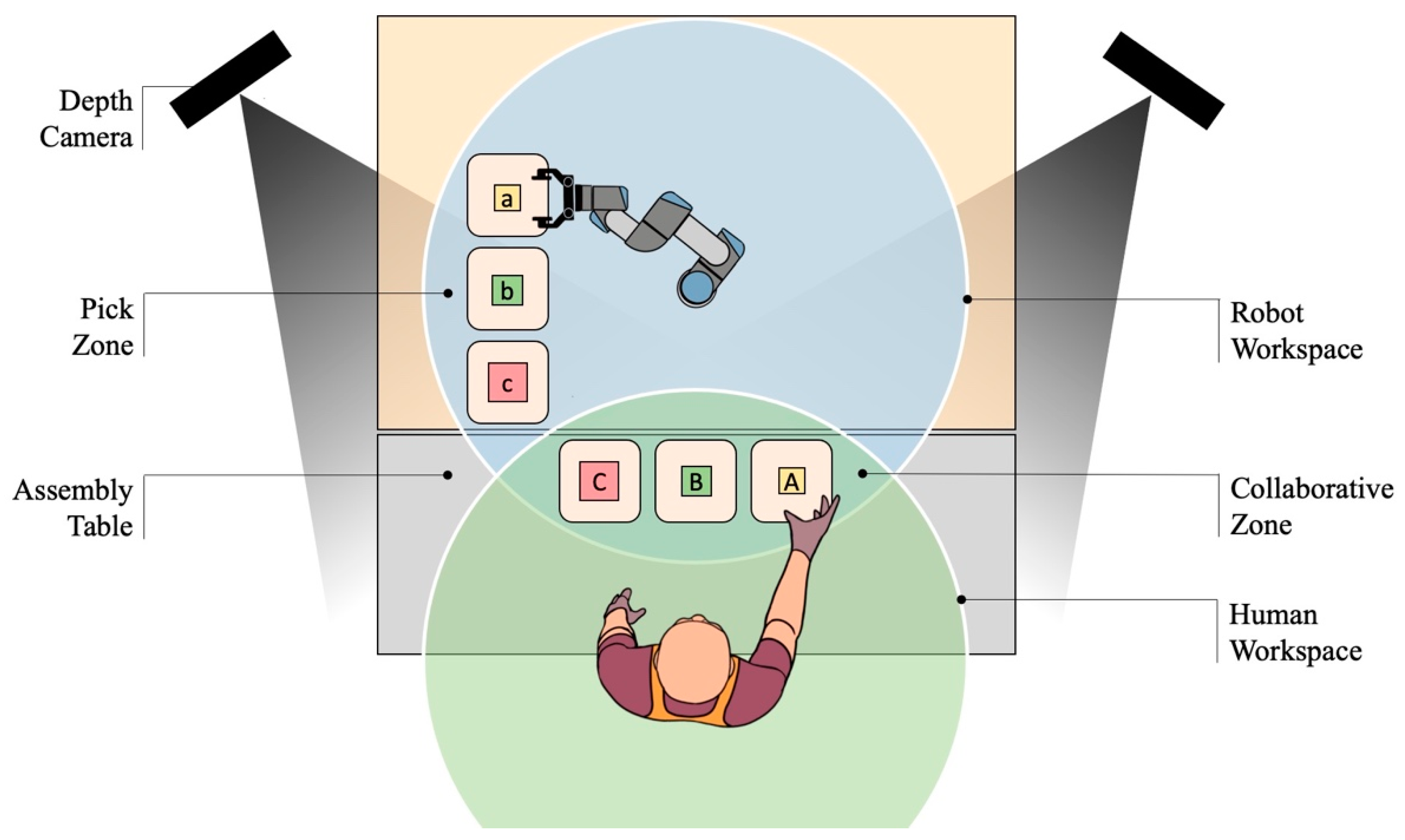
Figure 1. The entire task can be divided in two main operations: Collecting the components to be assembled and assembling them. Concerning the first operation, the components are supposed to be stored so that a robot can easily pick them up. The second operation is supposed to be too complex or too variable for a full automation solution, so that the human presence is required. For this reason, the operator should be able to take the parts to be assembled from a certain area which must be a portion of the robot workspace, since the robot has the role to provide the parts to the operator. With this aim, the workspace of the robot is divided in two zones, as shown in
Figure 2. The parts are stored in the “pick zone”, where no human presence is expected. In the “collaborative zone”, where the human and robot can potentially come to contact as their workspaces intersect, the operator takes the components to be assembled.
The human worker and robot perform seven operations in parallel to carry out the assembly task, as reported in
Figure 3. The task, which is also identified as a cycle, starts when the operator takes the cube positioned in station A. As the human hand enters in the collaborative zone, the robot task begins by replacing the cube in A with a new one from station a. In parallel, the operator puts the glue on the first cube, takes the second cube by station B, and prepares both cubes to be glued. The next step for the robot is taking a cube from station B and placing it in station B, to replace the one taken by the operator. Meanwhile, the human picks up the last cube in station C and assembles the tower of cubes. Finally, the robot replaces the cube in station C and returns in the home position, while the worker checks the edges of the assembly to remove the exceeding glue before delivering. Concerning the human task, the phases in which he takes the components happen in the collaborative zone, while the other phases are carried out on the assembly table, outside of the robot workspace. On the other hand, the “pick” stages of the robot task identify the robot motion in the pick zone, i.e., outside the collaborative zone, while the “place” stages identify the robot motion within the collaborative zone. The execution of these operations involves a responsive collaboration. In fact, as the human and robot carry out the subtasks in parallel, the operator can access the collaborative zone at any time, even if the robot is placing a component.
The laboratory setup of the collaborative assembly cell is visible in
Figure 4. Three PCs, two Microsoft Kinect v2, a router, and a collaborative robot UR3 from Universal Robots equipped with a Robotiq gripper 2F-85 are used. The three PCs are connected via Ethernet network and communicate using the TCP/IP protocol. The implemented algorithms are written in MATLAB environment. The two Kinect sensors are displaced at 1.5 m from the human, so that their field of view covers the entire workbench from different angles. Each Kinect can feedback depth data up to 30 Hz [
30]. Two PCs are connected to the Microsoft Kinect v2 cameras, to obtain the data acquired by each sensor. The third PC is connected to the controller of the UR3 robot. Further information related to the control strategy will be given in the next section.
3. Robot Control Strategy
The robot tool center point (TCP) motion is planned by combining planar trajectories that trigger and terminate at strategical nodes. When the robot moves above the stations of the components from the pick zone to the collaborative zone, the TCP planned trajectory is planar at
z = 0.3 m, where
z is measured from the robot mounting table. To grasp or release the cubes, the robot follows a vertical path. The strategical nodes are defined as the intersection points between the plane
z = 0.3 m and the vertical paths. For example, in
Figure 5 the main directions of the robot planned trajectory in the collaborative zone are shown, together with the
x and
y axis of the robot base. Regardless of the cube to be placed, the robot approaches the collaborative zone always from point
, then it navigates towards the station to be refilled. Once the component has been replaced, the robot drives backwards through the same path, returns in
, and leaves the collaborative zone. However, due to the human presence, the planned trajectory may deviate from the rectilinear paths. In fact, if the operator takes a component and gets close to the robot, which is going to replace another one, the risk of a collision occurs. Then, the robot planned trajectory is modified through the collision avoidance algorithm, which is discussed below.
Each Kinect gives as output the position of 25 points on the human body. These points will be indicated hereafter as skeleton [
30,
31]. The multiple sensors layout allows overcoming the problems related to occlusions of a single camera [
10]. However, the use of multiple sensors shifts the attention into the data fusion problem. One of the common techniques developed to merge the raw data obtained from the sensors consists of using a predefined skeleton fitted model [
32], while other techniques synthetize the skeletons generated by a couple of Kinects to better estimate the human joints position [
33]. In the system proposed here, an optimization problem is solved to properly combine the two skeletons. Further information related to the skeletons merging process and to the spatial matching are reported in [
19,
33].
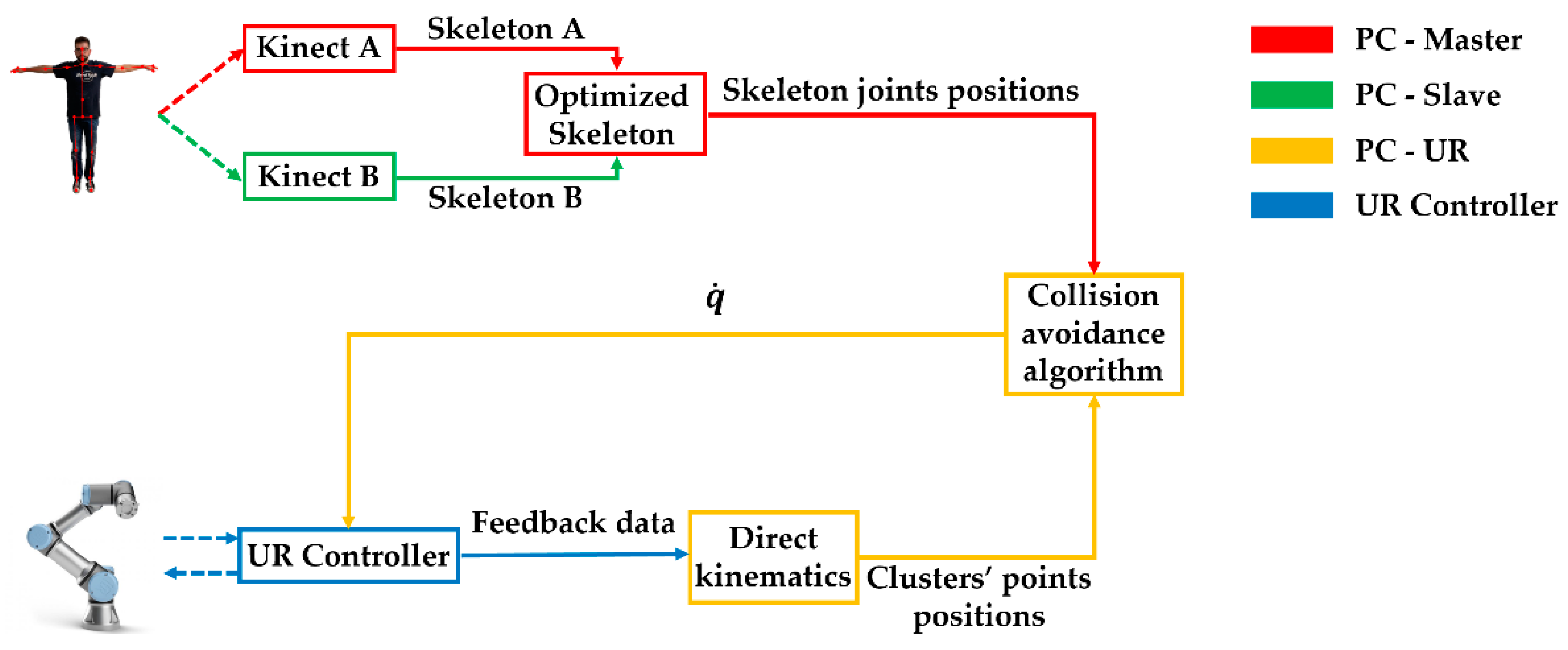
The two PCs connected to the Kinect sensors work in a master-slave architecture. The PC-Master is responsible for the data acquisition synchronization of the sensors, sending a trigger signal to the PC-Slave. The skeleton obtained by the PC-Slave is then sent to the PC-Master, that manages the combination of the skeletons acquired by the two Kinects. The optimized skeleton is calculated with a frequency of 30 Hz. The optimized skeleton is one of the inputs of the collision avoidance algorithm. The control algorithm runs in the third PC, hereafter called PC-UR. This PC receives the skeleton from the PC-Master and feedback data of the robot from the controller of the UR3. The feedback data related to the robot are described in [
34].
The collision avoidance algorithm is based on the artificial potential fields approach [
12,
35,
36,
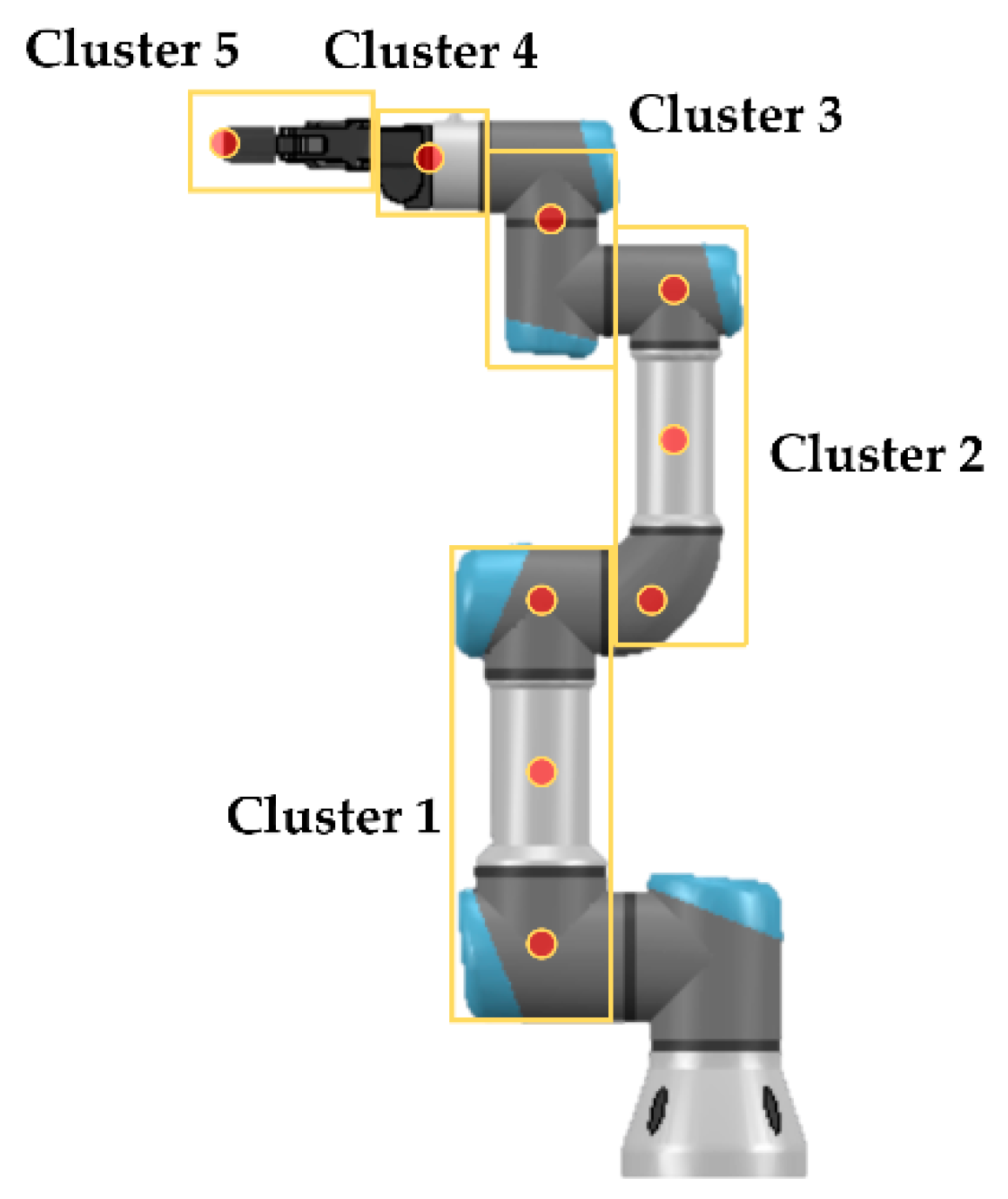
37] and permits avoiding collisions between the upper part of the human body and all the moving links of the robot. Repulsive velocities are associated to the operator and attractive velocities to the desired task. The repulsive and attractive velocities are then added up to obtain a resultant velocity, which is the output of the collision avoidance algorithm. In this way, the implemented control algorithm can modify the planned trajectory to move the robot away from the human operator, but the task is preserved and accomplished when human-robot collisions are no longer possible. Both the repulsive velocities and the attractive ones are calculated in the operative space. To avoid undesired contacts between the worker and the moving links of the manipulator, nine points, divided in five clusters, have been assumed within the robot, as seen in
Figure 6.
The positions of these reference points are calculated by direct kinematics, exploiting the feedback joint degrees of freedom provided by the UR controller. The distances between the human joints and the points on the UR3 robot are then evaluated using the
knnsearch algorithm [
38]. This algorithm, given as inputs of two sets of points
X and
Y (in this case the points are respectively the position vectors of the joints of the optimized skeleton and of the points of the clusters) finds the nearest neighbor in
X for each query point in
Y and gives as outputs the distances. Given the human-robot distances
, the repulsive velocities
are calculated for each
i cluster using the following equations:
where
is the maximum value of the magnitude of the repulsive velocity,
is the reference distance, and
is a shape factor. In this work, the magnitude
has been modelled as in
Figure 7. This curve is obtained with
= 0.3 m/s,
= 0.4 m, and
= 5, which have been used during the experimental phase. Concerning the value of
(that determines the distance between the control points on the robot and the skeleton that triggers the repulsive effect), even if it may seem quite conservative, takes into account the real dimensions of the human body and robot. In fact,
are point-to-point distances, so the human body and robot dimensions have been included in the reference distance
. Moreover,
also considers the position uncertainties of the operator and robot resulting from measurement tolerances of the sensing devices according to what is required by the standards. Concerning
and
, their values were chosen considering the TCP velocity during the pick-and-place phases, to obtain evasive movements of the robot from the operator which were smooth and seamless.
It is important to highlight that the values of the three parameters
,
, and
used in the experimental phase result in a safe collision avoidance in the sense that they can prevent the collision with the operator, even if the algorithm described in this section does not fully respect the equations related to the SSM presented in [
8]. In the technical specification, the value of the minimum human-robot distance is not constant and depends on several terms. The velocity of the human operator is one of the terms that modify the value of the minimum distance. In this work, a constant reference distance
was adopted and the influence of the human velocity was taken into account choosing sufficiently precautionary values of the three parameters involved in the calculation of the repulsive velocities.
Concerning the repulsive velocities associated to the points of Clusters 1 and 2, the distances
are the minimum human-robot distances of each cluster. Instead, concerning the TCP of the robot, which is Cluster 5 in
Figure 6, the repulsive velocity
is added to the attractive velocities associated to the task to obtain the resultant velocity
:
where
is the velocity vector associated to the planned task,
is a diagonal matrix, and
is the error vector, which is the difference between the desired pose of the TCP and the actual one. The orientation error is calculated considering the axis-angle convention [
39]. If the minimum human-robot distance is lower than a given threshold
even in presence of the repulsive velocities, the robot is stopped and it will move again when the minimum distance is greater than
.
The information useful to properly control the UR3 robot is the joint velocities vector
. Therefore, the velocities from the operative space have to be mapped to the joint space. The joint velocities vector
is calculated as follows:
where
is the geometric Jacobian matrix associated to the TCP and
is the partial Jacobian of each
i cluster. The joint velocities vector
is calculated with a frequency of 62.5 Hz and then sent to the controller of the UR3 to properly move the robot, in order to accomplish the task avoiding collisions with the human worker. Custom functions developed by the authors permit the communication between the PC-UR and controller of the robot, as reported in [
17]. A schematic representation of the control strategy is shown in
Figure 8. The scheme is divided in two parts: In the upper part, the data flow related to the acquisition of the movements of the human operator is reported, while the calculation process of the vector
is shown in the lower part of the scheme. Concerning the movements acquisition, the PC-Master and the PC-Slave firstly obtain the data related to the skeletons acquired by the two Kinect sensors. Then, the PC-Slave sends the skeleton to the PC-Master, which generates the optimized skeleton. The position vectors of the joints of the optimized skeleton are finally sent to the third PC. Meantime, the PC-UR has calculated the position of the points of the five clusters by direct kinematics, given the feedback data from the controller of the robot. The position vectors of the clusters’ points and of the skeleton joints are the inputs of the collision avoidance algorithm, that gives as output the joint velocities vector
. The joint velocities vector is sent to the UR-Controller every 0.016 ms.
4. Results and Discussion
The effectiveness of the proposed collaborative layout is evaluated in terms of safety and productivity. Concerning the safety, the experimental tests prove that the collision avoidance algorithm can quickly drive the robot through alternative trajectories in order to avoid the human.
Figure 9 shows an example of collision avoidance that happens when the robot is placing a↦A and the operator is taking B (for a more detailed overview of the entire assembly cycle the reader is referred to the video in “
Supplementary Materials”). For each frame, the MATLAB calculation environment is reported in the robot base reference frame. In the latter, the robot links are represented as blue lines, together with the nine control points. The optimized skeleton of the human upper body is colored in red and made of 15 significant joints. The robot planned trajectory is also shown as the rectilinear dashed path connecting
to
, while the solid line is the trace of the actual collision avoidance trajectory. The robot approaches the collaborative zone from point
and starts following the rectilinear planned path towards
, while the human is still applying the glue on the first cube (Frame 1). Then, the operator finishes preparing A (Frame 2) and takes B, while the robot is crossing the relative station, so that the robot reacts backwards to avoid the human hand (Frame 3). As the hand retracts, the robot returns on the planned path (Frames 4 and 5) and reaches
, while the human is preparing A+B (Frame 6).
The collision avoidance trajectory is analyzed in
Figure 10. The robot planned trajectory is also shown with the dashed line, together with the strategical points. To give an idea of the repulsive effect, the repulsive velocity vectors acting on the TCP are reported on the actual path at significant samples. The repulsive effect increases nearby
, which is the point above station B where the human takes the cube. Here, the actual path bends backwards due to the presence of the human hand. The operator takes the cube within a time interval of 1 s, so the repulsive effect is localized only on a limited portion of the collision avoidance path.
The possibility to carry out the task with the highest level of collaboration brings significant advantages in terms of task times. At the top of
Figure 11, the workflow diagram of the proposed assembly cell is shown. In this case, which represents a responsive collaboration, the human and the robot complete their task in the same time interval, resulting in a mean cycle time of 112 s. The human and robot tasks run in parallel and the robot collaborates while the human executes value added operations, i.e., actions that carry on the assembly process.
To stress the importance of this result, it is assumed that the same assembly cycle is carried out by considering the lowest level of collaboration. The latter identifies a sequential collaboration, where the human and robot workspaces intersect, but without the possibility for the human to access the collaborative zone if it is already occupied by the robot, and vice-versa. With this more restrictive safety constraint, the workflow diagram would be the one in the middle of
Figure 11. In fact, when the operator finishes preparing A, he cannot enter in the collaborative zone until the robot accomplishes the “Place a↦A” phase. After that, the robot leaves the collaborative zone and the operator can take B. This generates a first delay of approximately 23 s on the human’s task. A second delay of approximately 3 s would be at the end of the “Prepare A+B” phase, since the robot has not finished yet the “Place a↦A” stage and is still in the collaborative zone, therefore, the human must wait before he takes C. The mean cycle time, in this case, is 138 s. Comparing the latter result with the previous case, the major result is that the highest level of collaboration optimizes productivity by saving up to the 18% of the cycle time.
5. Conclusions
This work investigates the feasibility and the potential benefits of a collaborative assembly cell characterized by the highest level of collaboration. A practical and effective collaborative layout based on multiple Kinect cameras has been presented. Then, a representative assembly task which can take advantage from collaborative robotics has been chosen. The robot and operator carry out their task in parallel, with the possibility to operate at the same time in the shared workspace. An UR3 collaborative robot has been used for the experimental test. The robot control strategy has been discussed to describe a collision avoidance algorithm based on repulsive velocities. The algorithm has a low computational cost and can drive the robotic arm away from the human body represented as a skeleton. The result section has shown the capabilities of the proposed algorithm by analyzing the robot alternative trajectory. The robot is able to avoid the human and return on the planned path to carry on the task. Moreover, the cycle time has been compared for the cases of responsive and sequential collaboration. The highest level of collaboration, which has been tested in this work, promises significant improvement in terms of task time, even if the actual possible benefit should be carefully evaluated for each specific application.
Software and hardware improvements of the experimental setup will be involved in future works. The control algorithms will be written in a low-level programming language to package the code for real-time application in the industrial field. The Microsoft Kinect v2 sensors will be substituted by Azure Kinect DK [
40], which is the new RGBD camera by Microsoft, and the number of the PCs will be optimized. These software and hardware improvements will lead to a more efficient and cheaper experimental setup.
The authors are currently working on algorithms useful to predict the movements of the operator and evaluate his/her velocity using either vision sensors or wearable devices [
20,
21,
41]. These algorithms will permit strictly implementing the equations written in [
8] without considering that the velocity of the human operator is constant and equal to 1.6 m/s.
Furthermore, the application of the proposed layout in a real industrial scenario will be studied in the future.


 ,
, 
