Article

Establishment of a Rolling-Sliding Test Bench to Analyze Abrasive Wear Propagation of Different Bearing Materials for Knee Implants

1
Biomechanics and Implant Technology Research Laboratory, Department of Orthopaedics, University Medicine Rostock, Doberaner Str. 142, 18057 Rostock, Germany
2
Visual and Data-Centric Computing, Zuse Institute Berlin, Takustraße 7, 14195 Berlin, Germany
*
Author to whom correspondence should be addressed.
Appl. Sci. 2021, 11(4), 1886; https://doi.org/10.3390/app11041886
Submission received: 3 February 2021 / Revised: 17 February 2021 / Accepted: 18 February 2021 / Published: 21 February 2021

Abstract

:
Currently, new materials for knee implants need to be extensively tested but such tests are expensive in a knee wear simulator in a realized design. However, using a rolling-sliding test bench, these materials can be examined under the same test conditions, but with simplified geometries. In the present study, the test bench was optimized, and forces were adapted to the physiological contact pressure in the knee joint using the available geometric parameters. Various polymers made of polyethylene and polyurethane, articulating against test wheels made of cobalt-chromium and aluminum titanate, were tested in the test bench using adapted forces based on ISO 14243–1. Polyurethane materials showed distinctly higher wear rates than polyethylene materials and showed inadequate wear resistance for use as knee implant material. Thus, the rolling-sliding test bench is an adaptable test setup to evaluate newly developed bearing materials for knee implants. It combines the advantages of screening and simulator tests and allows for the testing of various bearing materials under physiological load and tribological conditions of the human knee joint. The wear behavior of different material compositions and the influence of surface geometry and quality can be initially investigated without the need to produce complex implant prototypes of total knee endoprosthesis or interpositional spacers.

1. Introduction

The knee is the largest synovial fluid-filled joint in the human body [1] and exhibits different articulating surfaces. The tibiofemoral joint is the weight-bearing component of the knee [1,2], consisting of two biconvex femoral condyles that articulate on a concave medial and a convex lateral plateau of the tibia. The complex structure of the native knee joint enables flexion and extension, anterior posterior (AP) translation, abduction and adduction, as well as axial rotation movements. The degree of freedom of knee movements is mainly limited by the ligaments [3]. The dominant movements are flexion and extension, where the femoral component performs a complex rolling-sliding movement on the tibial plateau. The ratio of rolling and sliding is determined by the extent of flexion [4,5]. At the beginning of the flexion movement, the rolling mechanism prevails. From approximately 20 to 30 degrees of flexion, rolling-sliding dominates until pure gliding occurs at the maximum degree of flexion movement. The extent of rolling-sliding is lower in the medial than in the lateral compartment [4,5,6]. The viscoelastic menisci ensures a consistent distribution of joint load [1].
Osteoarthritis is one of the most common diseases of the knee joint. Affected patients suffer from severe pain and reduced joint mobility, and are often treated with knee arthroplasty. This procedure is one of the most common surgical interventions in orthopedics [2]. However, one major problem of knee endoprostheses is their limited ability to replicate the natural rolling-sliding mechanism and wear propagation at bearing surfaces. Enhanced mechanical loading due to high physical activity influences the durability and functionality of knee implants [5,7]. One of the main causes of implant failure and revision is aseptic loosening due to the release of wear debris, accompanied by an adverse biological reaction to the particles [8,9].
Therefore, preclinical tribological and biological investigations on abrasive wear and deformation behavior are relevant for the development of suitable knee implant materials and designs. For this purpose, various wear test methods are available, which differ in complexity and testing parameters. These methods can be divided into screening and simulator studies [10]. Initial tribological screening tests mainly examine the contact surface over a short time period using simplified sample geometries and kinematics. The most commonly used test methods include pin-on-disc or cylinder-on-cylinder tests [7,10]. To simulate wear behavior under more physiological conditions, new endoprosthetic implant materials and designs need to be tested according to international testing standards, where advanced joint-specific motion sequences and load profiles are applied. However, these tests are time-consuming and the running costs for wear data acquisition are high. Furthermore, only finalized implant prototypes are tested regarding their wear behavior at articulating surfaces, which are complex to produce [7,10,11]. Before such implants are produced, a test device that enables the screening of new materials with simplified geometries under biomechanical boundary conditions, adapted to the in vivo situation, should be available. Some previous studies have introduced the concept of executing combined rolling-sliding movements while applying physiological joint forces and motions. In 2004, Citters et al. developed a rolling-sliding tribotester that was capable of generating realistic contact stresses [12]. The extent and frequency of rolling and sliding could be adjusted separately for each test station. Cylindrical samples of cobalt-chromium (CoCr) and polyethylene (PE) were tested in test fluid until macroscopic failure of the samples occurred [12,13]. However, the geometric contact conditions were simplified. Richter et al. [11] developed a test bench in which an axial load was applied statically with a cylinder made of CoCr to a horizontally moving plate made of PE, resulting in a rolling movement of the rotating cylinder on the plate. After stopping the CoCr cylinder, a sliding movement occurs due to the continuous movement of the PE plate in a tempered test fluid [11]. As this test chamber is not sealed, there is a risk of contamination by foreign particles. In another rolling-sliding test bench, an axial sinusoidal load is applied to a plate made of PE by means of a CoCr cylinder [14]. The rolling-sliding movement results from the horizontal movement of the test chamber. These test rigs represent an appropriate mixture of screening and simulator tests and are designed for wear and endurance testing. However, none of them replicate the dynamically acting load conditions in the human knee joint.
To address this, Goebel et al. developed a rolling-sliding test bench (RST) [7]. Comparable to the test benches of Wieser [14] and Richter et al. [11], the force is applied to a flat sample of PE using CoCr cylinders. The rolling-sliding movement is caused by the coupled movement of a lifting arm. With this test bench, the forces acting on the knee during normal gait can be dynamically and variably applied to the sample during the roll-slide movement [7]. Furthermore, it is possible to simulate the roll-slide movement of a femoral component made of CoCr under wear conditions that are as close as possible to physiological conditions [7]. However, this test bench has some limitations. Goebel et al. used the same force, according to ISO 14243–1 [15], that is used for the testing of total endoprostheses in knee wear simulators, although only one knee condyle was simulated on the test bench. Furthermore, the test bench had only one station, resulting in time-consuming sample screening [7].
In the present study, the test bench was optimized, and the forces were adapted to the physiological contact pressure in the knee joint using the available geometric parameters. In this study, a knee spacer, which is a unicompartmental interpositional implant, was developed with the aim to postpone the implantation of a unicondylar or bicondylar knee endoprosthesis. For this purpose, we adapted the test bench and test conditions described by Goebel et al. [7] to simulate the contact conditions of an osteoarthritic femoral condyle on the spacer material. Furthermore, a second station was added to the rolling-sliding test bench. The joint reaction force according to ISO 14243–1 [15] was adjusted to the load situation at the unicompartmental implant surface, and different bearing material pairs were compared.

2. Materials and Methods

2.1. Construction of the Rolling-Sliding Test Bench

In the test setup, the physiological rolling-sliding movement of the knee joint was transferred to a simple movement algorithm with simplified sample geometries, according to Schwittalle et al. [16]. The bearing components included a rolling cylinder, which was guided through a hole, with an additional pin to lock the rotation of the cylinder. This cylinder simulated one femoral condyle. The corresponding tibial plateau with an integrated insert was simulated by a flat polymer sample disc placed on an inclined metallic plane. The test bench applied flexion-extension movements. The application of the forces and movements of the femoral and tibial components was ensured by coupling to two electromechanical cylinders (CMS63S series; SEW-EURODRIVE GmbH and Co KG, Güstrow, Germany). The loads and movements of the cylinders could be freely adjusted using MOVITOOLS®-Motion-Studio software (SEW-EURODRIVE GmbH and Co KG, Güstrow, Germany). The test bench with the electromechanical cylinders was embedded in a frame constructed of anodized aluminum profiles. One pivoted electromechanical cylinder was used for the transmission of force (Figure 1), while the second electromechanical cylinder performed the rolling-sliding movement simultaneously in a kinematic chain.
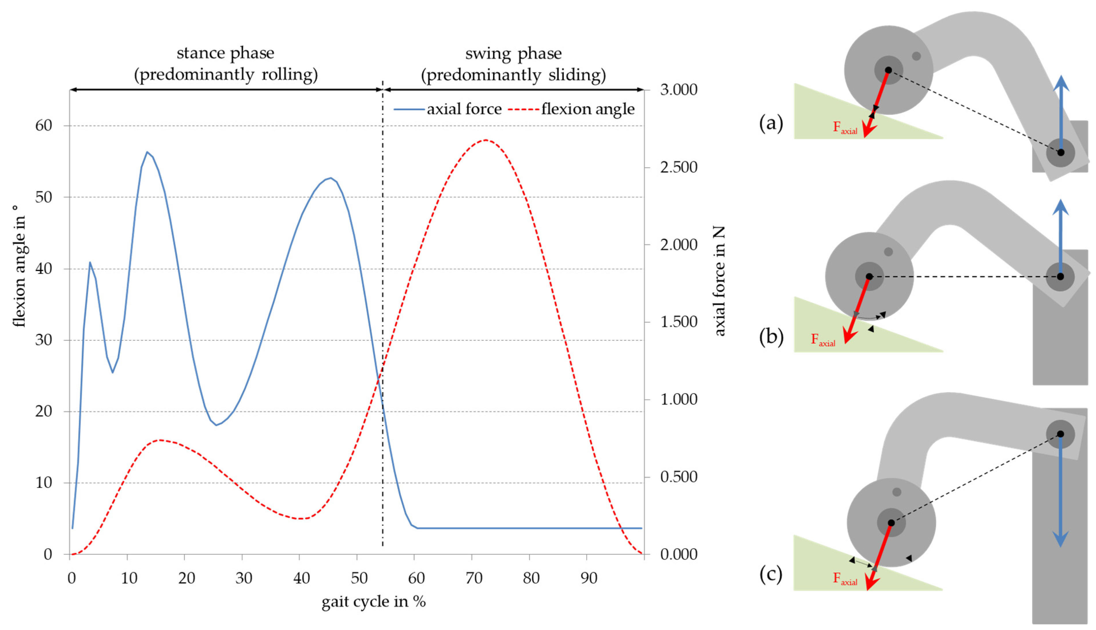
The rolling cylinder was firmly connected to a right-angled lever, which was connected to the lifting cylinder with a linear guide (see Figure 1) driven by an electromechanical cylinder. This enabled a consistent forward movement, whereby the cylinder rolled on the inclined plane through the rotation lock (Figure 2a). From half of the stroke length at 55 mm, the cylinder was rolled to the upper point (reversal point). The coupling point with the lifting cylinder was at the level of the center of rotation of the test wheel. With further lifting of the lifting cylinder, the coupling point rose higher than the center of the rotation and the test wheel slid down the inclined plane (Figure 2b). The lifting cylinder moved upwards for 110 mm, and the test wheel stopped at the lowest position on the bearing surface (Figure 2c). According to the physiological kinematics, the rolling of the test wheel occurred approximately during the first 55% of the gait cycle (see Figure 2, left panel). Subsequently, the pure sliding movement was simulated, which appeared in the knee at approximately 30° of flexion, corresponding to about 55% of the gait cycle. The linear movement of the lifting cylinder was adjusted in such a way that the roll-slide movement was completed after 1 s, thus completing a full gait cycle. Just as in the knee joint, the rolling-sliding test bench simulates movement of the rotation axis of the knee condyle. During the downward movement of the lifting cylinder, the rolling-sliding mechanism occurred in reverse order.
The sample was loaded axially with a force cylinder, which was coupled to the axis of the test wheel (Figure 1). The application of force by the first electromechanical cylinder was synchronized with the linear lifting movement driven by the second electromechanical cylinder. The force curve was freely programmable and could therefore be applied statically, and it was also time dependent. In order to simulate a physiological joint load, the force curve of normal walking, as specified in ISO 14232–1, was applied between the test wheel and the polymer sample [15]. Thus, the applied forces were correlated to the corresponding angles of the flexion-extension movement according to the ISO standard [7,15].
In order to simulate the physiological axial joint load, the applied force based on ISO 14243–1 was adapted to the prevailing physiological contact pressure of the condyles in the following section (see Section 2.3).
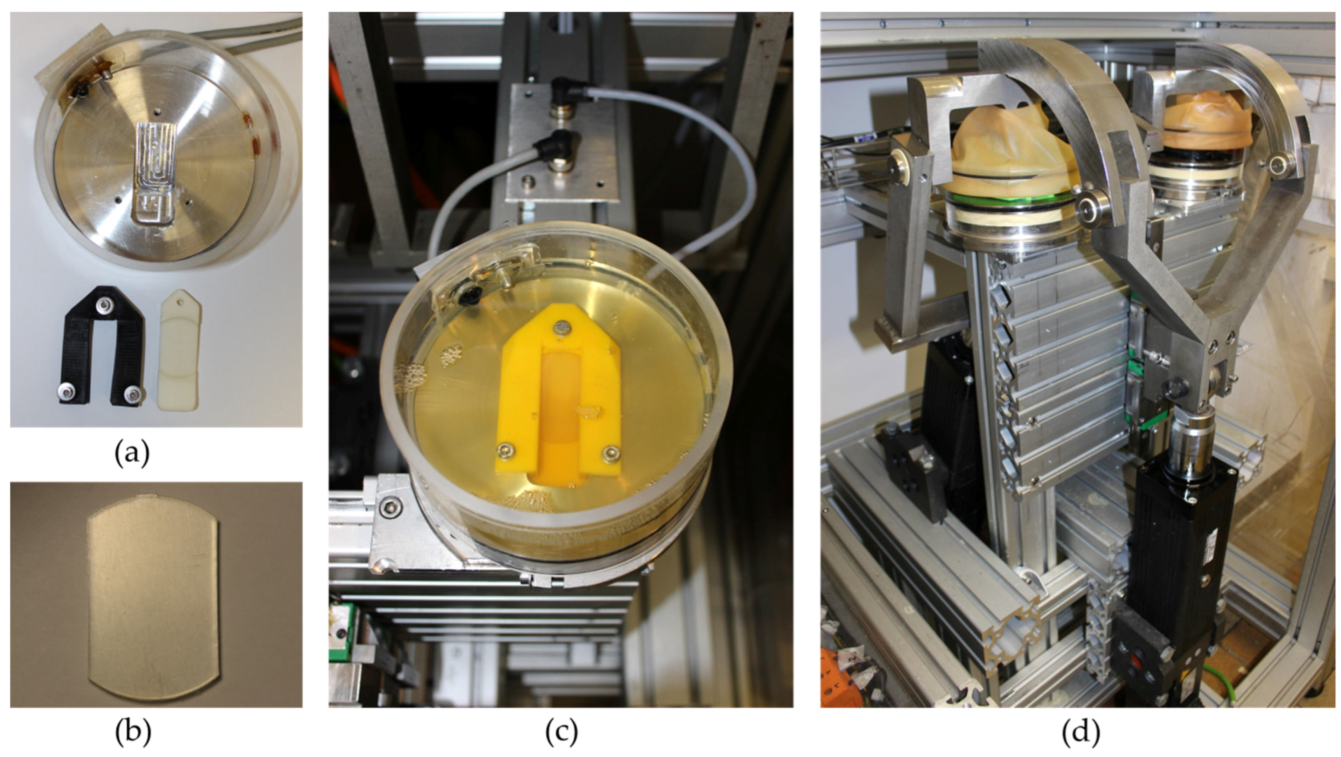
Goebel et al. [7] initially included one station in the test bench. In the present study, a second station, operating in parallel, was integrated into the test bench. For this purpose, a second force cylinder and a second pair of bearing surfaces were integrated in parallel to the first station with the same load profile. In order to apply an identical rolling-sliding movement, both stations were coupled with the lifting arm (Figure 3d).
To ensure that the polymer specimens were loaded identically and would not slip out of the holder during dynamic loading, they were fixed with a clamp (Figure 3a,c). This also prevented high backside abrasive wear. The bearing partners were loaded according to ISO 14243–1 at 1 ± 0.1 Hz at 37 ± 2 °C in 150 mL bovine serum with a protein content of 20 g/L [15]. These parameters were intended to simulate the environment of the human knee joint. Integrated level and temperature sensors allowed for long-term automated and controlled operation of the test bench. The test bench was made of stainless steel to prevent corrosion as well as third body wear through the chamber. The setup of the rolling-sliding test bench is shown in Figure 3. To ensure a load frequency of 1 ± 0.1 Hz, the feed force of the lifting cylinder must be adapted to the increased weight by coupling of the second station.
In the present study, interpositional implant samples made of polyurethane (PU), which should imitate cartilage and articulate against a simulated subchondral bone, were tested as an example. For this purpose, test wheels made of aluminum titanate (Alutit T; CeramTec GmbH, Plochingen, Germany) were used. This ceramic material has a similar Young’s modulus (17,000 MPa) to that of cortical bone. Furthermore, the bearing combination of a cobalt-chromium test wheel articulating against ultra-high-molecular-weight polyethylene was analyzed in the test bench with adapted contact forces.

2.2. Test Samples

The test samples (disks with a height of 3.5 mm, diameter of 40 mm, and cut to a width of 24 mm; see Figure 3b) were made of polyurethane and polyethylene. The test wheels (cylinders with a width of 12 mm and diameter of 60 mm) consisted of Alutit and CoCr. The samples were dynamically loaded in the test bench according to ISO 14243–1 [15]. For each sample material, one sample was loaded statically as a reference for fluid absorption [15]. As knee spacer materials, two thermoplastic polycarbonate urethane (TPCU) materials provided by the University of Applied Sciences, Reutlingen, were tested [17,18]. These polyurethane materials were tested using a ceramic test wheel made of thermal shock-optimized Alutit T.
To facilitate comparison to abrasion data from the knee simulator, a conventional ultra-high-molecular-weight polyethylene (GUR1050) sample was articulated against Alutit T and CoCr test wheels under the same conditions.

2.3. Adjustment of Load Pattern

According to ISO 14243–1 [15], forces between 0.17 and 2.6 kN occur in the human knee during the normal gait cycle. In the rolling-sliding test bench, tests were carried out with a cylindrical test wheel, which is considerably narrower than a knee condyle. Therefore, in order to achieve a roll-slide movement under physiological forces, the force specified by the ISO standard needed to be reduced. In addition to the different geometries, the differences in material properties, such as the elasticity of the bearing partners, also needed to be taken into account. Furthermore, it is important to consider that only one knee condyle is represented in the roll-sliding test bench. According to Hella et al., 70% of the axial force is transmitted with the medial condyle and 30% with the lateral condyle [19]. Hence, the spacer material was tested by simulating loading at the medial condyle.
In order to determine the force to be transferred between the two articulating surfaces, A and B, taking into account the geometry and material properties, the formula for the contact pressure according to Hertz (Equation (1)) was chosen, with consideration of the material parameters (Equation (2)) for the case of a cylinder (A) on a plane (B):
p H = F 2   π   r   l   ×   E 1 υ 2  
E 1 υ 2 = ( 1 υ A 2 E A + 1 υ B 2 E B ) 1
To calculate the forces for the roll-slide test rig, the physiological contact pressure in the human knee joint must first be determined. Therefore, the maximum axial force from ISO 14243–1 was considered. For the medial condyle, a maximum force of 2.6 kN resulted in an axial maximum force Fmedial of 1.82 kN. The knee spacer material tested in this study was developed for the treatment of knee joints with progressive osteoarthritis. Patients often suffer from a severe lesion of the femur cartilage down to the surface of the subchondral bone. Therefore, the contact model of cortical bone (femoral site) on cartilage (tibial site) was chosen for the determination of the contact pressure. The Young’s modulus and Poisson’s ratio of cortical bone, which were articulated against cartilage, were chosen as parameters to test the material properties of the bearing materials. Hayes and Mockros determined variable properties for long- and short-term loaded cartilage [20]. To ensure that the worst-case scenario is covered, we used the higher value for the short-term loaded cartilage to calculate the contact pressure on the articulating surface. Since progressive osteoarthritis often results in a joint space narrowing accompanied by meniscal extrusion, the meniscus was not taken into account for the calculation of the contact pressure [21]. To determine the radius and width of the medial condyle, it is necessary to ascertain the flexion axis according to the ISO norm. Since the knee does not have a fixed center of rotation and the flexion axis shifts to anterior with increasing flexion, this axis needs to be approximated for the determination. For an accurate determination, both parameters were measured at maximum force. According to ISO 14243–1, this occurs at 15.32° of flexion [15].

2.4. Shape Analysis for Parameter Detection

In order to measure parameters, we performed 3D surface reconstruction from magnetic resonance imaging (MRI) scans of 261 female femoral surfaces based on quality assured manual segmentations of the distal femur bone. The segmentations were part of the previously published OAI–ZIB dataset [22]. For further technical details, we refer the reader to that publication. We calculated the point-wise mean shape, a standard procedure in statistical shape modeling [23], and performed an error-minimizing cylinder fit to the condyle region with respect to the contact points obtained by virtually mimicking the flexion-rolling of the distal femur bone (see Figure 4a,b). The radius of the determined cylinder serves as parameter rmedial. Taking the center line of the fitted cylinder as the (flexion) axis, we intersected the medial condyle region with a plane deflected by 15.32° and adapted the resulting intersection curve to the load-bearing cartilage interface by restriction to the segment connecting the two points of maximal curvature. The parameter lmedial could then be defined as the Euclidean distance between these points (see Figure 4c). In contrast to most studies in which the condylar radius is determined by considering the condyles as independent spheres [24,25], this study fitted a cylinder around the flexion axis of both condyles. This approach was chosen because ISO 14243–1:2009 also takes the flexion axis into account when both condyles contact the tibial plateau. Furthermore, in the study by Howel et al. [24], only very small differences between the radii of the medial and lateral condyles of a human knee joint were determined (on average 0.1 to 0.2 mm, accompanied with high standard deviations), although the condyles were considered individually as spheres. As these are very small differences, we assume that the use of a cylinder in the determination of the radius is suitable.
The parameters used are summarized in Table 1.
This resulted in a constant value of E/(1 − υ2) = 14.56 N/mm2 for the bearing materials cortical bone on cartilage with the material parameters after insertion in Equation (2). This resulted in the following equation for the physiological contact pressure:
p H = F m e d i a l × 14.56   N / m m 2 2   π × 20.58   m m × 25.29   m m
In order to determine the force for the rolling-sliding test bench, Equation (1) had to be modified according to the force and the determined natural contact pressure with the geometric data and the material data of the samples to be tested. The geometric parameters used in the calculation were the radius (rRST = 30 mm) and width (lRST = 12 mm) of the rolling cylinder. The parameters of the bearing materials investigated in this study are summarized in Table 2.
F R S T = p H 2   2   π   r R S T   l R S T E / ( 1 υ 2 ) = p H 2   2   π × 30   m m × 12   m m E / ( 1 υ 2 )
with
E 1 υ 2 = ( 1 υ c y l i n d e r 2 E c y l i n d e r + 1 υ p l a n e 2 E p l a n e ) 1
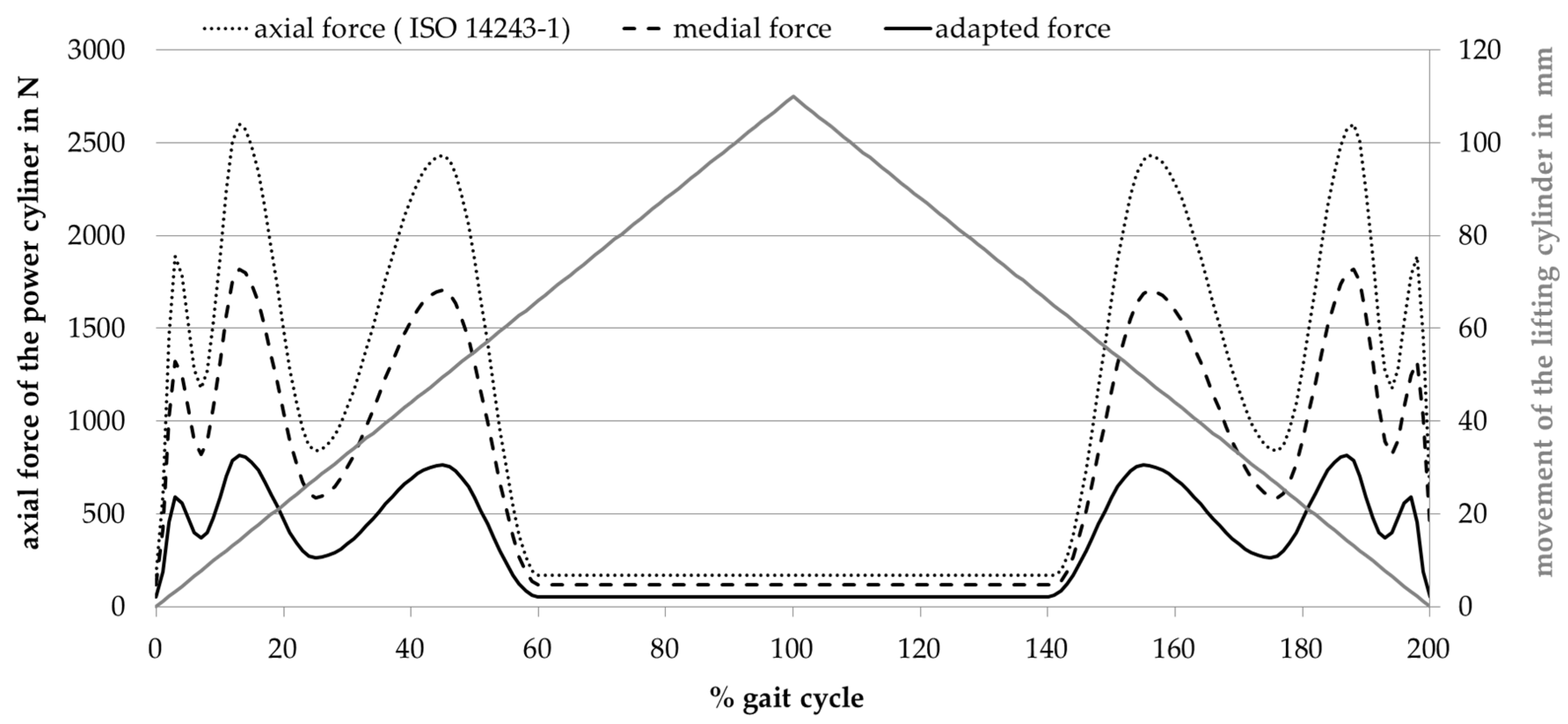
A material constant of E/(1 − υ2) = 22.47 N/mm2 was determined for the bearing material pair Alutit against PU, which resulted in a maximum force of 815.43 N. For CoCr against PE, a maximum force of 15.5 N was calculated with E/(1 − υ2) = 1179.42 N/mm2. For bearing material pair 3, Alutit against PE, a maximal force of 16.5 N was calculated with E/(1 − υ2) = 1111.24 N/mm2. For programming the rolling-sliding test bench, an adapted load curve was calculated using the force curve from ISO 14243–1. The computerized force curve for the two bearing materials, PU against Alutit, is shown in Figure 5.

2.5. Abrasive Wear Measurement

Similar to standard knee wear simulator tests, three samples of each pair of bearing materials were tested in the rolling-sliding test bench under dynamic loading, as well as an additional soak control. Before loading, the polymer samples were saturated in the test medium in accordance with ISO 14243–2 [30]. As the test fluid, bovine serum (protein content 20 g/L; Biochrom GmbH, Berlin, Germany), ethylene diamine tetra acetic acid (EDTA) and sodium azide (NaN3) were used. Deviating from the ISO standard, the load was applied with an adapted force profile in the rolling-sliding test bench with two stations over a million cycles in total, as the PU materials had already been subjected to severe wear during this period. To validate the fluid absorption of the inserts, the soak control was only loaded with the axial force. For this purpose, the rolling-sliding movement was inhibited by decoupling of the lifting cylinder so that no wear was generated in the soak control sample. To validate the progress of sample saturation and the measurement before loading, the weight of the samples was measured gravimetrically after 0.5 million and 1 million cycles using a high precision balance (Sartorius ME235S; Sartorius AG, Göttingen, Germany; sensitivity 0.01 mg, uncertainty 0.03 mg) with an accuracy of 0.1 mg, according to ISO 14243–2. The wear of the samples was determined, taking the fluid absorption of the soak control into account. Before the gravimetric measurement, the samples were cleaned and dried in accordance with ISO 14243–2 [30]. To avoid damaging the PU samples, they were not treated with propanol. To ensure an identical load of all samples and to avoid station-related influences, the samples were exchanged between the two stations every 0.5 million cycles. In addition, the medium was replaced, and the test chambers were cleaned. The serum was stored for further examination [15,30].

2.6. Surface Analysis and Roughness Measurement

After completion of the wear measurement analysis, optical surface analysis was carried out using a laser scanning microscope (LSM; VHX–900F; Keyence, Osaka, Japan). This was used to characterize the surface roughness and the patterns of wear that occurred. Measurements were made in the articulated area, in the area of clamping and in the unloaded area of the plane. The arithmetical mean height (Sa) and the maximum height (Sz) were determined according to DIN EN ISO 4288:1998 and DIN EN ISO 3274:1998 [31,32]. The wear patterns and roughness values were compared to the images and values of unloaded samples.

3. Results

3.1. Amount of Wear

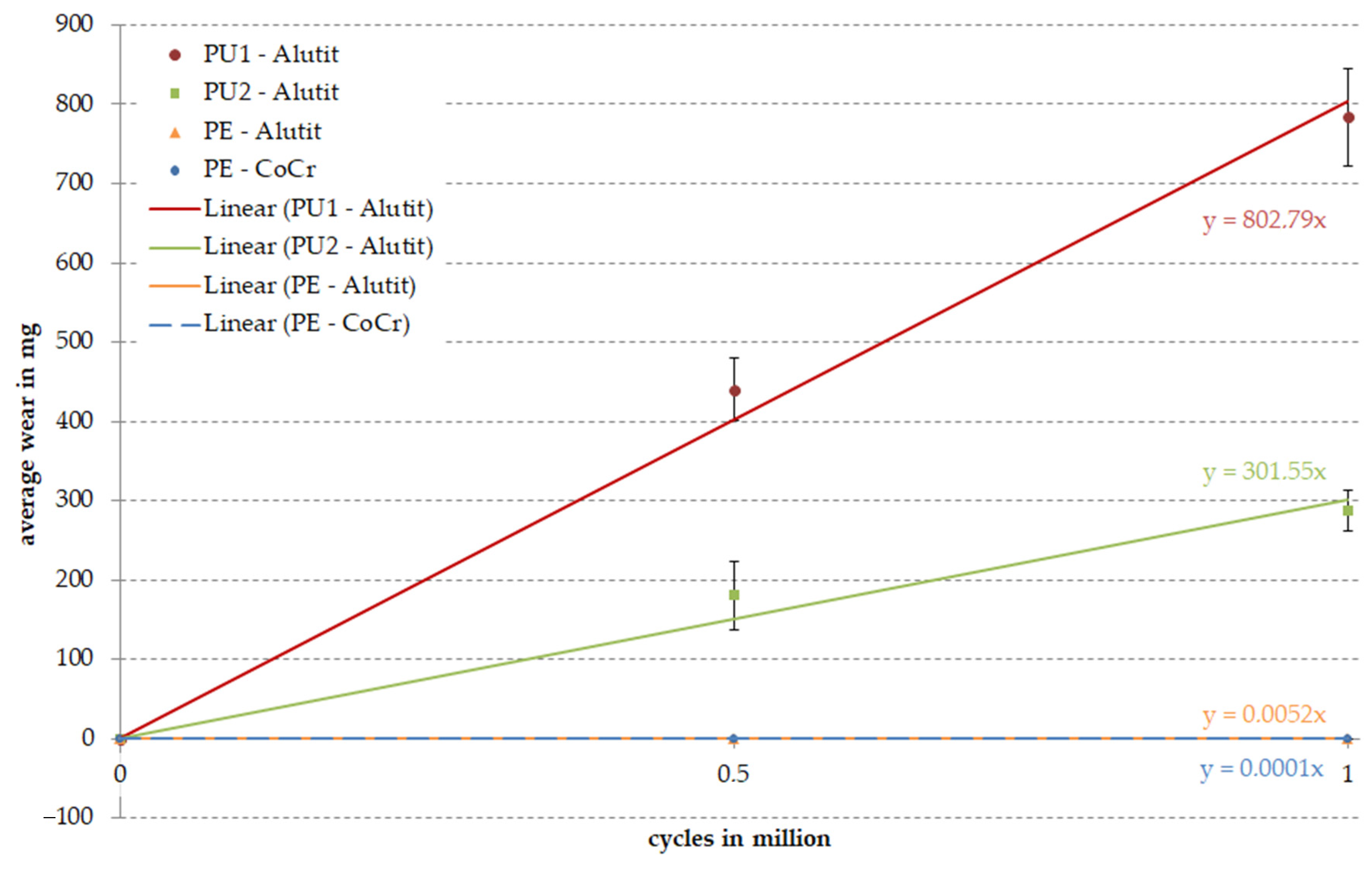
Four different bearing pairs were tested on the rolling-sliding test bench over one million cycles under standard conditions. We were unable to detect any signs of wear on the PE inserts articulated against the CoCr and Alutit test wheels after loading with 15.5 N (PE–CoCr) or 16.5 N (PE-Alutit); therefore, the PE inserts were also loaded with the higher force (815.43 N) from the pairing of Alutit against PU. The wear rates of the three test specimens were calculated for each pairing considering the material saturation with the test fluid (soak control). The worn running surface of the PU materials was about 35 mm, while the worn surface of the PE samples was distinctly flatter and shorter (20 mm). This is also reflected in the wear data presented in Figure 6. The mean gravimetric wear of the PU materials after one million cycles amounted to 1223.46 ± 87.02 mg for PU1 and 466.92 ± 69.44 mg for PU2. The PE material articulated against Alutit showed an average wear of 7.9 × 10⁻³ ± 2.0 × 10⁻⁴ mg after one million cycles. The wear rates of the PE samples articulated against CoCr were the lowest, with a rate of 2.5 × 10⁻⁴ ± 3.4 × 10⁻⁴ mg. All PU and PE samples showed significant backside wear respective to the measured amount of wear (Figure 7). The gravimetric wear after 0.5 million cycles was also included in the calculation of wear rates (Figure 6). All curves showed a linear wear behavior.

3.2. Surface Analysis and Roughness Measurement

After loading in the rolling-sliding test bench and the gravimetric measurement, the running surfaces of all samples were examined by LSM and compared to the initial state. The PU samples showed a higher penetration depth of the test wheel into the material (see Figure 7). All samples showed slight scratches and ruts along the direction of movement, as well as scattered pitting. The PU samples also showed partial delamination of the surface. Furthermore, partial smoothing of manufacturing marks could be found on the running surface of the PE samples. Pronounced backside wear was observed, particularly for the PU samples (Figure 7). The extent of the running surface and the strength of the backside wear were consistent with the wear rates.
To measure surface roughness, the parameters Sa and Sz were recorded. The measured roughness values are shown in Figure 8. The dynamically tested PU samples showed increased surface roughness of the running surface. The arithmetical mean height of the PE samples decreased while the maximum height stayed consistent, which was due to smoothing of the manufacturing marks. The PU1 material showed the highest roughness values. The soak control samples showed polished contact surfaces, and thus, reduced roughness compared to the initial state.

4. Discussion

Using the rolling-slide test bench described here, different knee implant materials with simple geometries can be tested under the physiological loading conditions of the knee joint. The applied force was adjusted in the test bench so that different tribological pairings could be tested at the same physiological contact pressure. Nevertheless, some limitations must be considered when using the test bench. The simplified geometries offer the advantage that new materials can initially be screened with an affordable cost and little effort. For further investigations, long-term tests in a wear simulator are required, which take into account realistic implant geometries. A further limitation is related to the simplification of the geometries, since there is a lack of anterior-posterior translation and rotational movements. Hence, no transverse motions can be generated, which are considered important for PE wear propagation [33,34]. However, because flexion and extension are the main directions of movement in the knee [3], this is only a minor limitation. In order to ensure consistent loading on the tested samples, both test chambers with samples have to be perfectly aligned under the test wheels of each station. Otherwise, station-related differences in the wear patterns may appear. Since congruent worn surfaces of the polymer samples could be observed in both stations after loading, an adequate alignment of both test chambers can be assumed. Likewise, during articulation, approximately one-third of the testing wheel surface was in contact with the running surface of the polymer samples in the two stations.
To prevent the results from being influenced by friction-related sample heating, various tribological situations (loading in a dry test chamber, loading in medium, static and dynamic loading, and loading at room temperature and with connected heating) were investigated in preliminary tests using a thermal imaging camera and temperature sensors. A maximum warming of 4 °C was detected only in the dry running test. Since no temperature differences of the PU sample were detected under lubricated test conditions with medium, the influence of friction on the temperature was considered to have a negligible effect. Temperature-dependent changes in sample volume during wear testing could be excluded. Furthermore, the rolling-sliding test bench allows only minor changes in the volume of samples.
Force curves according to ISO 14243–1 were adapted to the tested bearing material to simulate the same surface pressure that is present in the natural knee joint. In addition, load curves other than those from the ISO 14243–1 can be created, and, if necessary, they can be adapted to specific material and load cases. Higher loading or other gait patterns, such as stair climbs, can be implemented in the rolling-sliding test bench based on data derived from biomechanical studies [35]. Since native cartilage is a material with nonlinear behavior, the use of the Hertzian contact model as a contact model for the transmission of the physiologically acting contact pressure represents a limitation of our test bench. Since samples with linear material behavior are tested in this study and a complete simulation of the conditions in the native knee joint is not possible, we assume this simplification is suitable for the present study. Madeti et al. [36] has also used a Hertzian contact model to determine physiological surface pressure. An even more accurate determination of the surface contact pressure could be achieved using multibody models [37,38]. Hence, nonlinear material models for cartilage or acting muscle forces may be considered in future studies.
Since the developed soft PU materials showed high abrasive wear during preliminary tests, the PU samples were only tested over 1 million cycles instead of 5 million cycles, as recommended in ISO 14243–1. A high amount of wear is also reflected in the increased surface roughness of the PU samples. To exclude the influence of laser scanning on the sample material during the surface analysis, this was carried out only after wear testing of the samples was complete.
Since PE is an established bearing material in total knee arthroplasty, it was used as the reference material. In contrast to PU, no significant abrasive wear could be detected when the PE samples were loaded with 15.5 N or 16.5 N. To ensure comparability between PE and PU, the same force curve was used for all materials tested. Therefore, for the algorithmic estimation of condyle radius and contact length, we examined three datasets consisting of only female, only male, or both male and female data. We found that the radius and contact lengths for females are smaller than males by a few millimeters (radius ~2.5 mm, contact length ~4 mm). Hence, we considered only female data for the final evaluation because a lower radius and contact lengths, together with constant force, as specified by ISO 14243–1, result in a higher surface contact pressure (cf. Equation (1)). Implant materials should be designed not only for an average load situation, but also for severe conditions. Thus, by selecting appropriate datasets, the adjustment of applied forces to specific patient groups (for example, by age or sex) can be easily accomplished.
ISO 14243–1 specifies that the samples should be subjected to a load of more than 5 million cycles. Furthermore, due to running-in behavior, the abrasion rate should only be determined after 0.5 million cycles. The high wear rates of PU samples in the current study suggest that this material is not suitable as a direct bearing partner for a unicompartmental interpositional knee implant. Since no comparable wear studies on PU in the knee joint using physiological rolling-sliding movements have been carried out to date, it is not possible to classify the abrasive wear rates of PU materials. Our results were not consistent with the findings of Schwartz et al. [39], who showed lower wear rates for PU than for PE materials. However, a direct comparison of both studies is not possible due to non-comparable methods. We assume that the high wear rates of PU materials observed in the current study are related to the different properties of the material, and not the geometry of the test bench. The observed high wear rates were partly caused by pronounced backside wear of the PU materials. The wear patterns of the surface and backside of the samples correspond to the determined wear rates of the samples. On the PE samples, only polishing and smoothing of the manufactured surface was observed. The test wheels were able to sink much deeper into the PU samples during loading, which led to massive ruts in the direction of movement. Partial delamination of the PU surface was observed. However, we cannot conclude that the high backside wear and the high wear rates of the PU materials are caused only by abrasive wear and not adhesive wear. Nevertheless, PU could potentially be used in other human joints with reduced loading and friction, such as finger joints.
The rolling-sliding test bench was successfully established as a tribological testing method. In order to test even more samples in parallel, it would be useful to expand this test bench with additional stations. In contrast to a knee wear simulator according to ISO 14243–1, simplified implant geometries can be used in the rolling-sliding test bench. Hence, the effort required to produce test prototypes of new implant materials for the first abrasive wear screening is reduced. Due to the simplified implant geometry and design of the test bench, reduced lubricant volumes are required when compared to knee wear simulator tests. The reduction of the amount of lubricating fluid leads to additional cost savings. The wear data of the PU materials can be classified due to the direct comparison of their wear rates with a clinically established PE material. A comparative study using same bearing materials to compare our rolling-sliding test bench with the standard knee wear simulator should be carried out in further validation studies. Compared to other screening tests, such as those that use a tribometer, the rolling-sliding test bench allows testing under conditions that are more similar to physiological conditions. Further, the material of the sample and the material of the test wheel as well as the lubricating medium can be varied. For the rolling-sliding test bench, wear particles released from the material sample during testing can be isolated from the lubricant and analyzed according to ISO 14243–1.

5. Conclusions

The rolling-sliding test bench was successfully established through the application of load profiles adjusted to realistic contact pressures. The rolling-sliding test bench combines the advantages of screening and simulator tests, allowing for the testing of various bearing materials under physiological load and tribological conditions of the human knee joint. Therefore, both the wear behavior of different materials and the influence of the surface geometry and quality can be further investigated without the need to produce complex implant prototypes of total knee endoprosthesis or interpositional spacers. Hence, the test bench allows the suitability of new implant materials as bearing materials to be checked prior to further testing, where promising materials and surface modifications are subjected to advanced testing in a knee wear simulator in their final implant design.

Author Contributions

Conceptualization, J.H., F.A., S.Z. and R.B.; methodology, J.H. and F.A.; software, F.A.; validation, J.H.; formal analysis, J.H. and F.A.; investigation, J.H.; resources, S.Z. and R.B.; data curation, J.H. and F.A.; writing—original draft preparation, J.H. and F.A.; writing—review and editing, J.H., F.A., S.Z. and R.B.; visualization, J.H. and F.A.; supervision, S.Z. and R.B.; project administration, S.Z. and R.B.; funding acquisition, R.B. All authors have read and agreed to the published version of the manuscript.

Funding

This research was funded by the German Federal Ministry of Education and Research within the project TOKMIS (grant numbers 01EC1406F and 01EC1406E). This research did not receive any specific grant from commercial or not-for-profit sectors.

Institutional Review Board Statement

Not applicable.

Informed Consent Statement

Not applicable.

Data Availability Statement

Data is contained within the article.

Acknowledgments

We would like to thank the German Federal Ministry of Education and Research (BMBF) for facilitating the implementation of the TOKMIS project (grant numbers 01EC1406F and 01EC1406E) in addition to our project partners at the University of Applied Sciences, Reutlingen, for provision of the test samples. The authors thank the mechanical workshop of the Institute of Physics, University of Rostock, for manufacturing the components for the test bench and Mario Jackszis for his support with the installation and alignment of the test bench.

Conflicts of Interest

The authors declare no conflict of interest.

References

  1. Drake, R.L.; Vogl, W.; Mitchell, A.W.M. Drake, Gray’s Anatomie SC; Elsevier, Urban&FischerVerlag: Munich, Germany, 2007; ISBN 978-3-437-41231-8. [Google Scholar]
  2. Krukemeyer, M.G.; Möllenhoff, G. Endoprothetik: Ein Leitfaden für den Praktiker, 3rd ed.; De Gruyter: Berlin, Germany, 2013; ISBN 978-3-11-028261-0. [Google Scholar]
  3. Faller, A.; Schünke, M. Der Körper des Menschen: Einführung in Bau und Funktion; Georg Thieme Verlag: Stuttgart, Germany, 2016; ISBN 978-3-13-151957-3. [Google Scholar]
  4. Nägerl, H.; Frosch, K.H.; Wachowski, M.M.; Dumont, C.; Abicht, C.; Adam, P.; Kubein-Meesenburg, D. A novel total knee replacement by rolling articulating surfaces. In vivo functional measurements and tests. Acta Bioeng. Biomech. 2008, 10, 55–60. [Google Scholar]
  5. Abicht, C. Artifical Knee Joints Following the Principle of a Four-Bar Linkage—Concept, Design and Tribological Properties of a New Natural Shaped Knee Endoprosthesis; Ernst-Moritz-Arndt-Universität, Medizinische Fakultät: Greifswald, Germany, 2006. [Google Scholar]
  6. Kapandji, I.A.; Koebke, J. Funktionelle Anatomie der Gelenke: Obere Extremität—Untere Extremität—Rumpf und Wirbelsäule, 5th ed.; Georg Thieme Verlag: Stuttgart, Germany, 2009; ISBN 978-3-13-142215-6. [Google Scholar]
  7. Goebel, P.; Zietz, C.; Bieck, R.; Kluess, D.; Bader, R. A novel method for tribological evaluation of bearing materials in total knee replacements. Biomed. Tech. Eng. 2012, 57. [Google Scholar] [CrossRef]
  8. Robertsson, O.; Lidgren, L.; Sundberg, M.; W-Dahl, A. The Swedish Knee Arthroplasty Register—Annual Report 2018; Lund University Department of Clinical Sciences, Orthopedics Skåne University Hospital: Holmgrens, Malmö, Sweden, 2019. [Google Scholar]
  9. Abu-Amer, Y.; Darwech, I.; Clohisy, J.C. Aseptic loosening of total joint replacements: Mechanisms underlying osteolysis and potential therapies. Arthritis Res. Ther. 2007, 9, S6. [Google Scholar] [CrossRef] [Green Version]
  10. Kretzer, J.; Zietz, C.; Schröder, C.; Reinders, J.; Middelborg, L.; Paulus, A.; Sonntag, R.; Bader, R.; Utzschneider, S. Grundlagen zur tribologischen Analyse von Endoprothesen. Der Orthopäde 2012, 41, 844–852. [Google Scholar] [CrossRef]
  11. I Richter, B.; Ostermeier, S.; Turger, A.; Denkena, B.; Hurschler, C. A rolling-gliding wear simulator for the investigation of tribological material pairings for application in total knee arthroplasty. Biomed. Eng. Online 2010, 9, 24. [Google Scholar] [CrossRef] [Green Version]
  12. Van Citters, D.W.; Kennedy, F.E.; Currier, J.H.; Collier, J.P.; Nichols, T.D. A Multi-Station Rolling/Sliding Tribotester for Knee Bearing Materials. J. Tribol. 2004, 126, 380–385. [Google Scholar] [CrossRef]
  13. Van Citters, D.W.; Kennedy, F.E.; Collier, J.P. Rolling sliding wear of UHMWPE for knee bearing applications. Wear 2007, 263, 1087–1094. [Google Scholar] [CrossRef]
  14. Wieser, J. Testung Unterschiedlicher Polyethylene im Roll-Gleit-Prüfstand. Text. Ph.D. Thesis, Ludwig-Maximilians-Universität München, Munich, Germany, 2014. [Google Scholar]
  15. ISO 14243-1:2009 Implants for Surgery—Wear of Total Knee-Joint Prostheses—Part 1: Loading and Displacement Parameters for Wear-Testing Machines with Load Control and Corresponding Environmental Conditions for Test. Available online: https://www.iso.org/cms/render/live/en/sites/isoorg/contents/data/standard/04/42/44262.html (accessed on 18 June 2020).
  16. Schwitalle, M.; Just, A.; Mark, T.; Bodem, F.; Schwitalle, E.; Koller, S. Kinematische Analyse vor und nach bikondylaerem Oberflaechenersatz des Kniegelenks. Der Orthopäde 2003, 32, 266–273. [Google Scholar] [CrossRef]
  17. Kutuzova, L.; Athanasopulu, K.; Schneider, M.; Kandelbauer, A.; Lorenz, G.; Kemkemer, R. In vitro bio-stability screening of novel implantable polyurethane elastomers. Curr. Dir. Biomed. Eng. 2018, 4, 535–538. [Google Scholar] [CrossRef]
  18. Athanasopulu, K.; Kutuzova, L.; Thiel, J.; Lorenz, G.; Kemkemer, R. Enhancing the biocompatibility of siliconepolycarbonate urethane based implant materials. Curr. Dir. Biomed. Eng. 2019, 5, 453–455. [Google Scholar] [CrossRef]
  19. Heller, M.O.; Taylor, W.R.; Perka, C.; Duda, G.N. The influence of alignment on the musculo-skeletal loading conditions at the knee. Langenbeck’s Arch. Surg. 2003, 388, 291–297. [Google Scholar] [CrossRef] [PubMed]
  20. Hayes, W.C.; Mockros, L.F. Viscoelastic properties of human articular cartilage. J. Appl. Physiol. 1971, 31, 562–568. [Google Scholar] [CrossRef]
  21. Adams, J.; McaLindon, T.; Dimasi, M.; Carey, J.; Eustace, S. Contribution of meniscal extrusion and cartilage loss to joint space narrowing in osteoarthritis. Clin. Radiol. 1999, 54, 502–506. [Google Scholar] [CrossRef]
  22. Ambellan, F.; Tack, A.; Ehlke, M.; Zachow, S. Automated segmentation of knee bone and cartilage combining statistical shape knowledge and convolutional neural networks: Data from the Osteoarthritis Initiative. Med Image Anal. 2019, 52, 109–118. [Google Scholar] [CrossRef] [PubMed]
  23. Ambellan, F.; Lamecker, H.; Von Tycowicz, C.; Zachow, S. Statistical Shape Models: Understanding and Mastering Variation in Anatomy. In Advances in Experimental Medicine and Biology; Springer International Publishing: Basel, Switzerland, 2019; Volume 1156, pp. 67–84. [Google Scholar]
  24. Howell, S.M.; Howell, S.J.; Hull, M.L. Assessment of the Radii of the Medial and Lateral Femoral Condyles in Varus and Valgus Knees with Osteoarthritis. J. Bone Jt. Surg.-Am. Vol. 2010, 92, 98–104. [Google Scholar] [CrossRef] [PubMed] [Green Version]
  25. Sancisi, N.; Parenti-Castelli, V. A sequentially-defined stiffness model of the knee. Mech. Mach. Theory 2011, 46, 1920–1928. [Google Scholar] [CrossRef]
  26. Schultze, C.; Klüss, D.; Martin, H.; Hingst, V.; Mittelmeier, W.; Schmitz, K.-P.; Bader, R. Finite-Elemente-Analyse einer zementierten, keramischen Femurkomponente unter Berücksichtigung der Einbausituation bei künstlichem Kniegelenkersatz/Finite element analysis of a cemented ceramic femoral component for the assembly situation in total knee arthroplasty. Biomed. Tech. Eng. 2007, 52, 301–307. [Google Scholar] [CrossRef]
  27. Mattei, L.; Di Puccio, F.; Piccigallo, B.; Ciulli, E. Lubrication and wear modelling of artificial hip joints: A review. Tribol. Int. 2011, 44, 532–549. [Google Scholar] [CrossRef]
  28. Kluess, D.; Martin, H.; Mittelmeier, W.; Schmitz, K.-P.; Bader, R. Influence of femoral head size on impingement, dislocation and stress distribution in total hip replacement. Med Eng. Phys. 2007, 29, 465–471. [Google Scholar] [CrossRef]
  29. Eichmiller, F.; Tesk, J.A.; Croarkin, C.M. Mechanical Properties of Ultra High Molecular Weight Polyethylene NIST Reference Material RM 8456. Soc. Biomater. 2001, 22, 6. [Google Scholar]
  30. ISO 14243-2:2009 Implants for Surgery—Wear of Total Knee-Joint Prostheses—Part 2: Methods of Measurement. Available online: https://www.iso.org/standard/69851.html (accessed on 18 June 2020).
  31. DIN EN ISO 4288:1998 Geometrische Produktspezifikation (GPS)—Oberflächenbeschaffenheit: Tastschnittverfahren—Regeln und Verfahren für die Beurteilung der Oberflächenbeschaffenheit (ISO 4288:1996); Beuth Verlag: Berlin, Germany, 1998. [CrossRef]
  32. DIN EN ISO 3274:1998 Geometrische Produktspezifikationen (GPS)—Oberflächenbeschaffenheit: Tastschnittverfahren—Nenneigenschaften von Tastschnittgeräten (ISO 3274:1996); Beuth Verlag: Berlin, Germany, 1998. [CrossRef]
  33. Jin, Z.; Fisher, J. Tribology in joint replacement*Note: This chapter is an updated version of Chapter 2, from the first edition of Joint replacement technology, edited by P. A. Revell and published by Woodhead Publishing, 2008*. Jt. Replace. Technol. 2014, 31–61. [Google Scholar] [CrossRef]
  34. Sivananthan, S.; Goodman, S.; Burke, M. Failure mechanisms in joint replacement**Note: This chapter is an updated version of Chapter 12, from the first edition of Joint replacement technology, edited by P. A. Revell and published by Woodhead Publishing, 2008. Jt. Replace. Technol. 2014, 370–400. [Google Scholar] [CrossRef]
  35. Taylor, W.R.; Heller, M.O.; Bergmann, G.; Duda, G.N. Tibio-femoral loading during human gait and stair climbing. J. Orthop. Res. 2004, 22, 625–632. [Google Scholar] [CrossRef] [PubMed]
  36. Madeti, B.K.; Rao, C.S.; Rao, B.S.S. Failure analysis of ACL and Hertz contact stress in human knee. Int. J. Biomed. Eng. Technol. 2014, 16, 317. [Google Scholar] [CrossRef]
  37. Machado, M.; Flores, P.; Claro, J.C.P.; Ambrósio, J.; Silva, M.; Completo, A.; Lankarani, H.M. Development of a planar multibody model of the human knee joint. Nonlinear Dyn. 2010, 60, 459–478. [Google Scholar] [CrossRef]
  38. Khoshgoftar, M.; Vrancken, A.; Van Tienen, T.; Buma, P.; Janssen, D.; Verdonschot, N. The sensitivity of cartilage contact pressures in the knee joint to the size and shape of an anatomically shaped meniscal implant. J. Biomech. 2015, 48, 1427–1435. [Google Scholar] [CrossRef] [Green Version]
  39. Schwartz, C.J.; Bahadur, S. Development and testing of a novel joint wear simulator and investigation of the viability of an elastomeric polyurethane for total-joint arthroplasty devices. Wear 2007, 262, 331–339. [Google Scholar] [CrossRef]
Figure 1. Rolling-sliding test bench (a) initially developed by Goebel et al. [7]; (b) enhanced with a second station and tempered testing chamber (c); with a lifting cylinder and linear guide (1, blue arrow indicates the direction of movement), pivoted force cylinder (2, red arrow indicates the direction of applied forces), right-angled lever (3), rolling cylinder (4, CoCr) with a rotation lock pin, and the sample on an inclined plane fixed with a yellow clamp (5).
Applsci 11 01886 g001
Figure 2. Motion sequence of the rolling-sliding test bench with the corresponding force according to ISO 14243–1 [15]: (a) Starting position of the lifting cylinder and rolling of the cylinder during lifting; (b) end of rolling and start of sliding down the plane; and (c) end of the motion sequence and start of the reverse cycle by sinking of the lifting cylinder.
Applsci 11 01886 g002
Figure 3. Setup of the rolling-sliding test bench. (a) Testing chamber with the sample clamp (black) and sample holder (white), (b) prepared polyurethane (PU) sample for testing, (c) tempered testing chamber with the fixed PU sample (yellow clamp) in test fluid, and (d) rolling-sliding test bench with two testing stations.
Applsci 11 01886 g003
Figure 4. Algorithmic estimation of condyle radius and width. (a) Contact points of simulated flexion movement on the distal femur; (b) optimal cylinder fitted to the contact points; and (c) curve along and through the medial condyle approximating the describing contact for a flexion angle of 15.32°.
Applsci 11 01886 g004
Figure 5. Adapted load curve in the rolling-sliding test bench and corresponding movement of the lifting cylinder.
Applsci 11 01886 g005
Figure 6. Overall wear of samples after loading in the rolling-sliding test bench. The straight line results from linear regression of the data for estimating the abrasion after 1 million cycles. Different to ISO 14243–1, the zero time point is used in this calculation.
Applsci 11 01886 g006
Figure 7. Worn surfaces (each left) and backsides (each right) of the three tested materials: (a) PU1, (b) PU2, and (c) PE.
Applsci 11 01886 g007
Figure 8. Surface roughness of the running surfaces of the tested samples before (left bars) and after (right bars) the wear test.
Applsci 11 01886 g008
Table 1. Parameters used to determine the physiological contact pressure in the medial knee joint.
ParameterValueMeaning
F0.17 to 2.6 kNAxial force according to ISO 14243–1 [15]
Fmedial0.12 to 1.82 kNAxial force that is transmitted via the medial condyle (Fmedial = 70% F [19])
rmedial20.584 mmCylinder radius/radius of the condyle
lmedial25.29 mmLength of contact of the cylinder with the plane/cartilage surface
EA = Ecortical bone17,000 N/mm2Young’s modulus of cortical bone [26]
υA = υcortical bone0.3Poisson’s ratio of cortical bone [26]
EB = Ecartilage12 N/mm2Young’s modulus of cartilage [20]
υB = υcartilage0.42Poisson’s ratio of cartilage [20]
Table 2. Parameters used to determine the axial load curves in the rolling-sliding test bench.
ParameterBearing Material Pair 1Bearing Material Pair 2Bearing Material Pair 3
Alutit T 1PUCoCr
[27]
PE
[28,29]
Alutit TPE
Ecylinder in N/mm217,000-230,000-17,000-
υcylinder0.22-0.3-0.22-
Eplane in N/mm2-18.9-945-945
υplane-0.4-0.45-0.45
1 Specified by the manufacturer.
Publisher’s Note: MDPI stays neutral with regard to jurisdictional claims in published maps and institutional affiliations.