
Online Distributed Measurement of Dark I-V Curves in Photovoltaic Plants

 , ,
, ,  ,
,  ,
,  , and
, and 
Abstract
:1. Introduction
2. Materials and Method
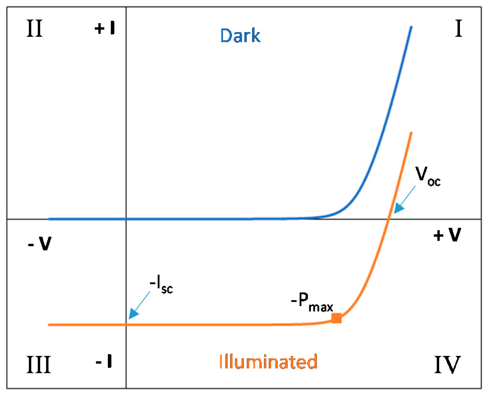
2.1. Dark I-V Curves
2.2. Power Inverter with Bidirectional Power Flow Capability
2.3. Electronic Board Integrated in Photovoltaic Modules
- First, in dark conditions, the Isc current is driven from the bidirectional inverter towards the modules string in a forward biased way (opposite of the current flow in production while in daylight). This establishes a voltage in the module terminals, and the circuit is powered up.
- When the I-V tracing is demanded from the external computer via a serial port, the MOSFET M1 is closed, subtracting all the current from the module, thus driving the module to zero voltage.
- The current sweep and the current and voltage measurements are started simultaneously. The MOSFET is pushed from its initial closed state to an open state; then, the module voltage returns to its maximum, and the I-V tracing is finished. The maximum current value is the one fixed initially in the bidirectional inverter (Isc).
- The microcontroller sends the data corresponding to the I-V curve to the external computer, and the circuit returns to the idle mode.
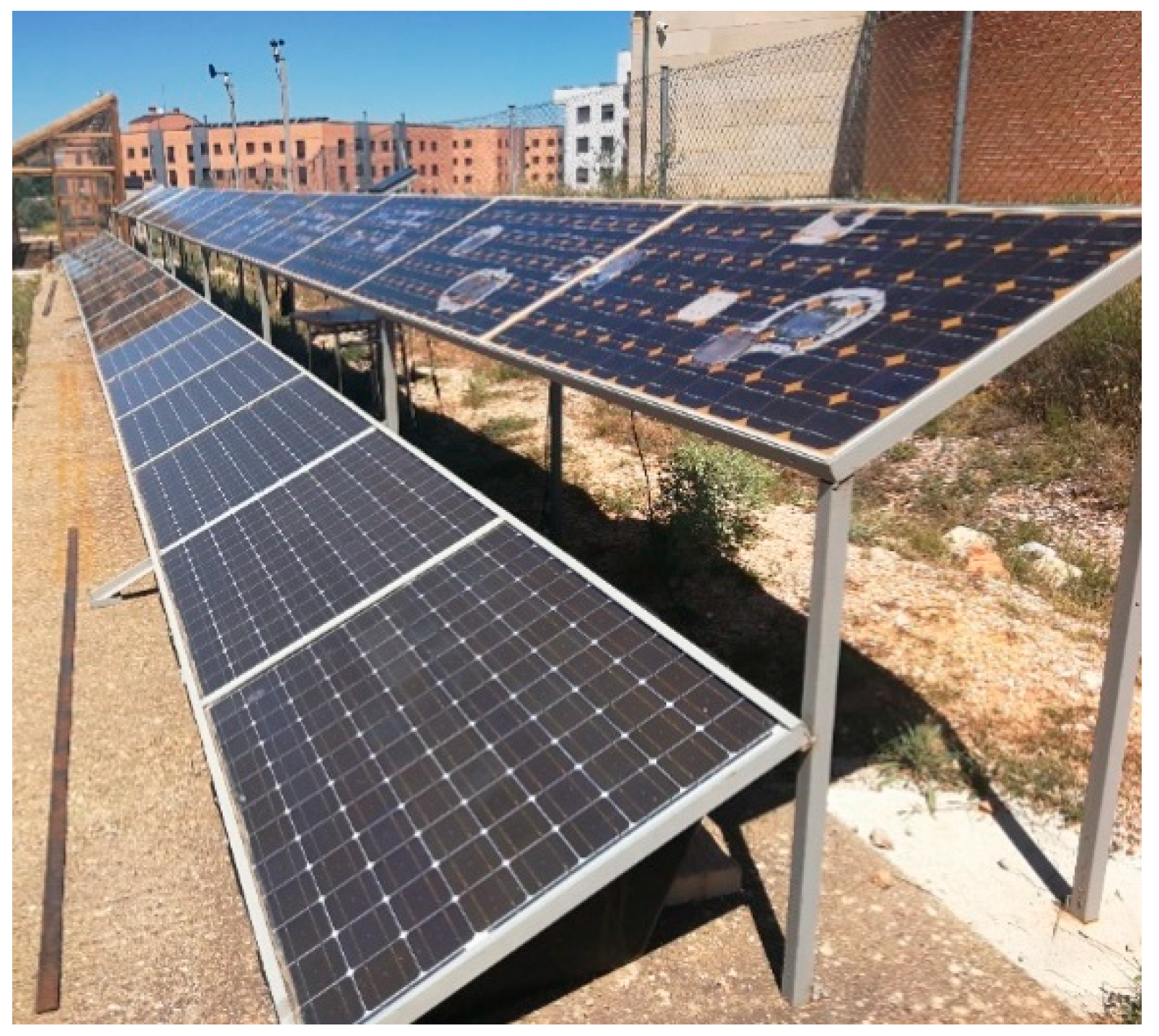
2.4. Tested Modules
2.5. Method
3. Results and Discussion
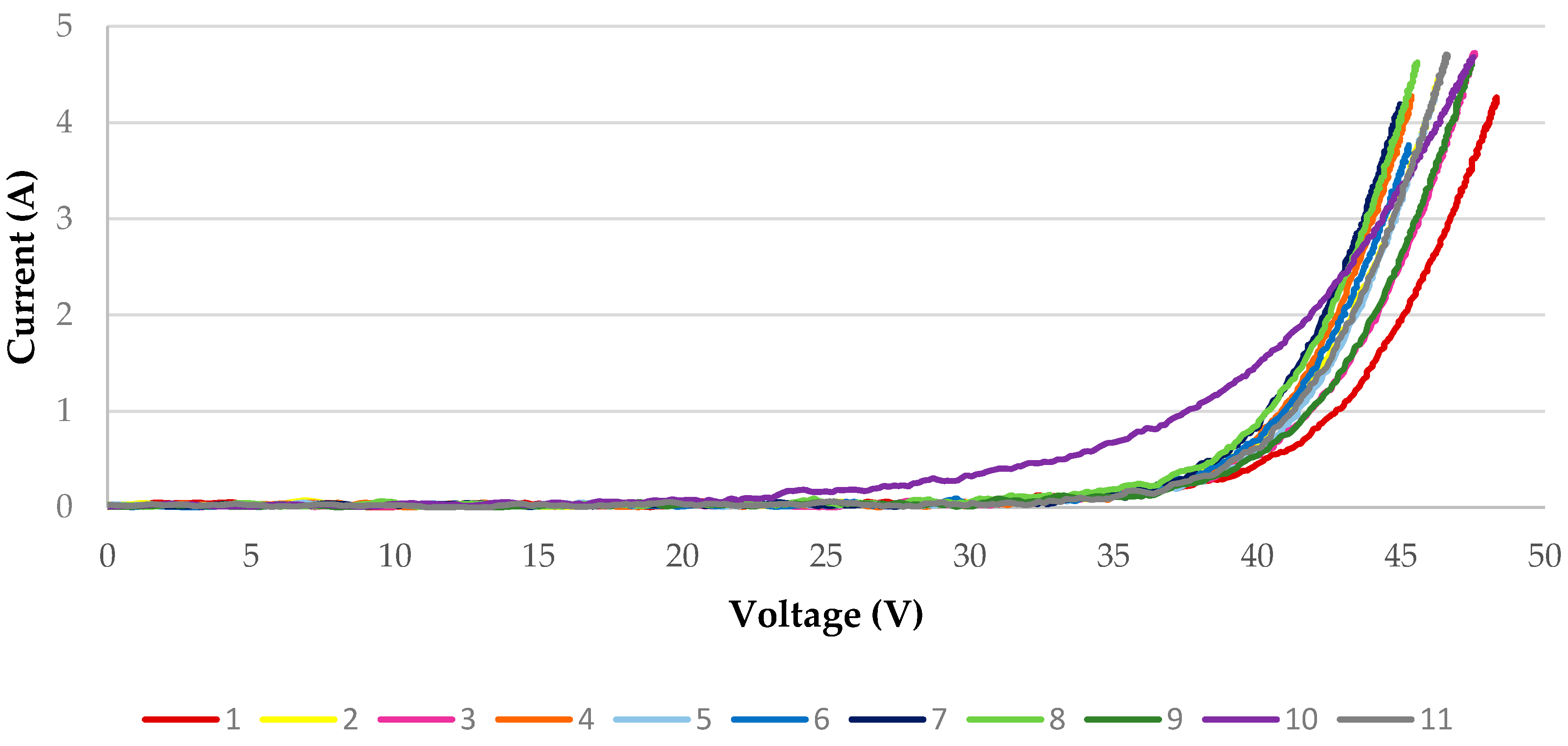
3.1. Dark I-V Curves Onsite Measurements
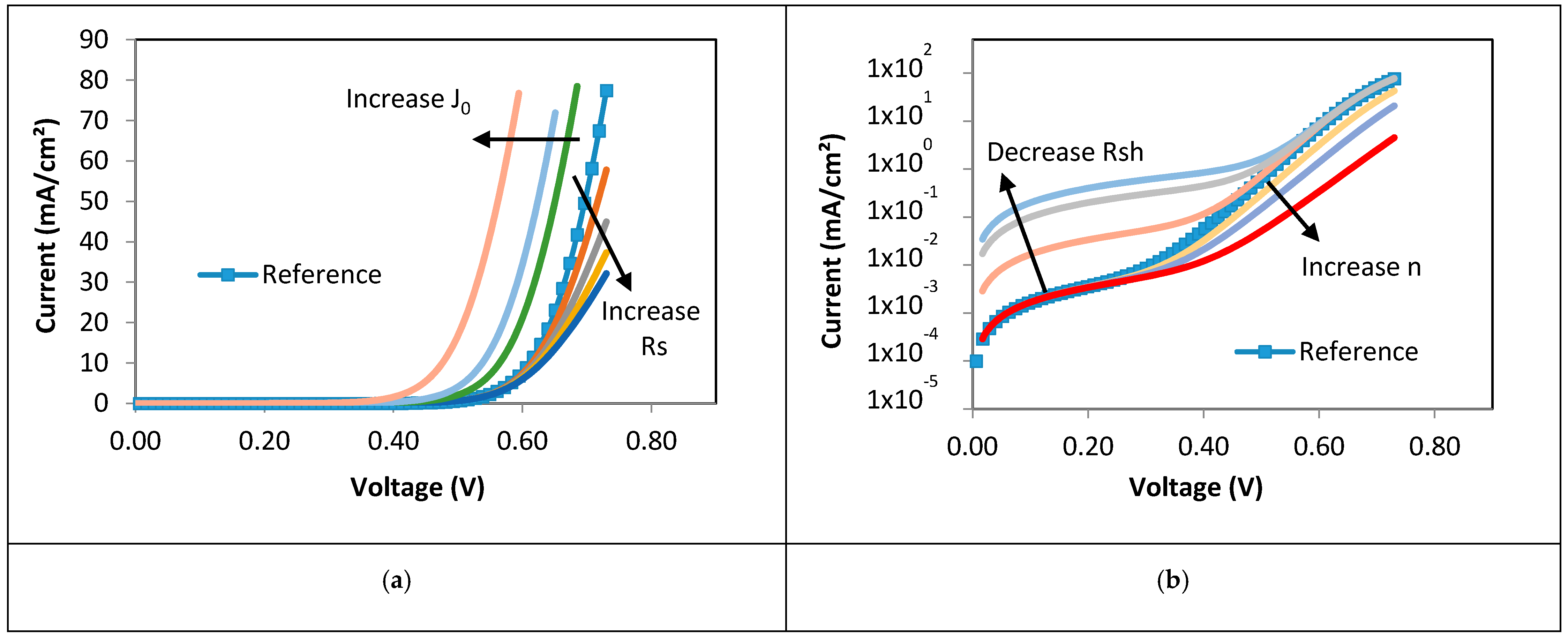
3.2. Extraction of Solar Module Parameters from the Measured Dark I-V Curves
4. Conclusions
Author Contributions
Funding
Data Availability Statement
Conflicts of Interest
References
- Solar Power Europe Global Market Outlook For Solar Power/2020–2024. Available online: www.solarpowereurope.org (accessed on 15 July 2020).
- International Energy Agency. Photovoltaic Power Systems. In Snapshot of Global PV Markets 2020; International Energy Agency: Paris, France, 2020. [Google Scholar]
- International Energy Agency. World Energy Outlook 2020. Executive Summary; International Energy Agency: Paris, France, 2020. [Google Scholar]
- International Electrotechnical Comission. International Electrotechnical Comission. Working Group 2: Solar Photovoltaic Energy Systems; International Electrotechnical Comission: Geneva, Switzerland, 2010. [Google Scholar]
- Klise, G.T.; Balfour, J.R.; Keating, T.J. Solar PV O&M Standards and Best Practices—Existing Gaps and Improvement Efforts; Sandia National Lab. (SNL-NM): Albuquerque, NM, USA, 2014. [Google Scholar]
- Hill, R.R.; Klise, G.; Balfour, J.R. Precursor Report of Data Needs and Recommended Practices for PV Plant Availability, Operations and Maintenance Reporting; Sandia National Laboratories: Albuquerque, NM, USA, 2015. [Google Scholar]
- National Renewable Energy Laboratory (NREL). Best Practices for Operation and Maintenance of Photovoltaic and Energy Storage Systems, 3rd ed.; National Renewable Energy Laboratory (NREL): Golden, CO, USA, 2018. [Google Scholar]
- Solar Power Europe. Operation & Maintenance Best Practice Guidelines/Version 4.0; SolarPower Europe: Brussels, Belgium, 2019. [Google Scholar]
- Tsanakas, J.A.; Ha, L.; Buerhop, C. Faults and infrared thermographic diagnosis in operating c-Si photovoltaic modules: A review of research and future challenges. Renew. Sustain. Energy Rev. 2016, 62, 695–709. [Google Scholar] [CrossRef]
- Gallardo-Saavedra, S.; Hernández-Callejo, L.; Alonso-García, M.D.C.; Muñoz-Cruzado-Alba, J.; Ballestín-Fuertes, J. Infrared thermography for the detection and characterization of photovoltaic defects: Comparison between illumination and dark conditions. Sensors 2020, 20, 4395. [Google Scholar] [CrossRef] [PubMed]
- Roumpakias, E.; Bouroutzikas, F.; Stamatelos, A. On-site Inspection of PV Panels, Aided by Infrared Thermography. Adv. Appl. Sci. 2016, 1, 53–62. [Google Scholar] [CrossRef]
- Teubner, J.; Buerhop, C.; Pickel, T.; Hauch, J.; Camus, C.; Brabec, C.J. Quantitative assessment of the power loss of silicon PV modules by IR thermography and its dependence on data-filtering criteria. Prog. Photovolt. Res. Appl. 2019, 27, 856–868. [Google Scholar] [CrossRef]
- Dunderdale, C.; Brettenny, W.; Clohessy, C.; van Dyk, E.E. Photovoltaic defect classification through thermal infrared imaging using a machine learning approach. Prog. Photovolt. Res. Appl. 2020, 28, 177–188. [Google Scholar] [CrossRef]
- Jahn, U.; Herz, M.; Rheinland, T. Review on Infrared (IR) and Electroluminescence (EL) Imaging for Photovoltaic Field Applications; International Energy Agency: Paris, France, 2018. [Google Scholar]
- Muttillo, M.; Nardi, I.; Stornelli, V.; de Rubeis, T.; Pasqualoni, G.; Ambrosini, D. On field infrared thermography sensing for PV system efficiency assessment: Results and comparison with electrical models. Sensors 2020, 20, 1055. [Google Scholar] [CrossRef] [PubMed] [Green Version]
- Köntges, M.; Kurtz, S.; Packard, C.; Jahn, U.; Berger, K.A.; Kato, K.; Friesen, T.; Liu, H.; Van Iseghem, M. Review of Failures of Photovoltaic Modules; International Energy Agency: Paris, France, 2014. [Google Scholar]
- Berardone, I.; Lopez Garcia, J.; Paggi, M. Quantitative analysis of electroluminescence and infrared thermal images for aged monocrystalline silicon photovoltaic modules. In Proceedings of the 2017 IEEE 44th Photovoltaic Specialist Conference (PVSC), Washington, DC, USA, 25–30 June 2017; IEEE: Piscataway, NJ, USA, 2018; pp. 402–407. [Google Scholar]
- Köntges, M.; Siebert, M.; Hinken, D. Quantitative analysis of PV-modules by electroluminescence images for quality control. In Proceedings of the 24th European Photovoltaic Solar Energy Conference, Hamburg, Germany, 21–25 September 2009; pp. 3226–3231. [Google Scholar]
- Santos, J.D.; Valverde, A.; Alonso-García, M.C. Quantitative Analysis of Electroluminescence Imaging of a pv module with different mismatch levels. In Proceedings of the 36th European Photovoltaic Solar Energy Conference and Exhibition, Marseille, France, 9–13 September 2019; pp. 1127–1133. [Google Scholar]
- Koch, S.; Weber, T.; Sobottka, C.; Fladung, A.; Clemens, P.; Berghold, J.; Koch, S.; Weber, T.; Sobottka, C.; Fladung, A.; et al. Outdoor Electroluminescence Imaging of Crystalline Photovoltaic Modules: Comparative Study Between Manual Ground-Level Inspections and Drone-Based Aerial Surveys. In Proceedings of the 32nd European Photovoltaic Solar Energy Conference and Exhibition, Munich, Germany, 20–24 June 2016; pp. 1736–1740. [Google Scholar]
- Wolf, M.; Rauschenbach, H. Series resistance effects on solar cell measurements. Adv. Energy Convers. 1963, 3, 455–479. [Google Scholar] [CrossRef]
- Celik, A.N.; Acikgoz, N. Modelling and experimental verification of the operating current of mono-crystalline photovoltaic modules using four- and five-parameter models. Appl. Energy 2007, 84, 1–15. [Google Scholar] [CrossRef]
- Ciulla, G.; Lo Brano, V.; Di Dio, V.; Cipriani, G. A comparison of different one-diode models for the representation of I-V characteristic of a PV cell. Renew. Sustain. Energy Rev. 2014, 32, 684–696. [Google Scholar] [CrossRef]
- Zhu, Y.; Xiao, W. A comprehensive review of topologies for photovoltaic I–V curve tracer. Sol. Energy 2020, 196, 346–357. [Google Scholar] [CrossRef]
- Pérez, L.; Coello, J.; Domínguez, F.; Navarrete, M. Development and implementation of a mobile laboratory—PV mobile Lab quality assurance of photovoltaic modules “on site”. In Proceedings of the 28th European Photovoltaic Solar Energy Conference and Exhibition, Paris, France, 30 September–4 October 2013; pp. 3500–3504. [Google Scholar]
- Coello, J.; Pérez, L.; Domínguez, F.; Navarrete, M. On-site quality control of photovoltaic modules with the PV MOBILE LAB. Energy Procedia 2014, 57, 89–98. [Google Scholar] [CrossRef] [Green Version]
- Morales-Aragonés, J.I.; Hernández-Callejo, L.; Gallardo-Saavedra, S.; Alonso-Gómez, V.; Sánchez-Pacheco, F.J.; González-Rebollo, M.A.; Martínez-Sacristán, O.; Muñoz-García, M.A.; Alonso-García, M.C. Low cost electronics for online I-V tracing at photovoltaic module level: Development of two strategies and comparison between them. Electronics 2021. under review. [Google Scholar]
- Bouzidi, K.; Chegaar, M.; Aillerie, M. Solar cells parameters evaluation from dark I-V characteristics. Energy Procedia 2012, 18, 1601–1610. [Google Scholar] [CrossRef]
- Martil, I.; Gonzalez Diaz, G. Determination of the dark and illuminated characteristic parameters of a solar cell from I-V characteristics. Eur. J. Phys. 1992, 13, 193–197. [Google Scholar] [CrossRef]
- King, D.L.; Hansen, B.R.; Kratochvil, J.A.; Quintana, M.A. Dark current-voltage measurements on photovoltaic modules as a diagnostic or manufacturing tool. In Proceedings of the Conference Record of the IEEE Photovoltaic Specialists Conference, Anaheim, CA, USA, 29 September–3 October 1997; pp. 1125–1128. [Google Scholar]
- Spataru, S.V.; Sera, D.; Hacke, P.; Kerekes, T.; Teodorescu, R. Fault identification in crystalline silicon PV modules by complementary analysis of the light and dark current–voltage characteristics. In Proceedings of the Progress in Photovoltaics: Research and Applications, 29th EU PVSEC, Amsterdam, The Netherlands, 2014; Volume 24, pp. 517–532. [Google Scholar]
- Spataru, S.; Hacke, P.; Sera, D. In-Situ Measurement of Power Loss for Crystalline Silicon Modules Undergoing Thermal Cycling and Mechanical Loading Stress Testing; National Renewable Energy Laboratory (NREL): Golden, CO, USA, 2015. [Google Scholar]
- Spataru, S.; Hacke, P.; Sera, D.; Packard, C.; Kerekes, T.; Teodorescu, R. Temperature-dependency analysis and correction methods of in situ power-loss estimation for crystalline silicon modules undergoing potential-induced degradation stress testing. Prog. Photovolt. Res. Appl. 2015, 23, 1536–1549. [Google Scholar] [CrossRef]
- Alonso-Garcia, M.C.; Hacke, P.; Glynn, S.; Muzzillo, C.P.; Mansfield, L.M. Analysis of Potential-Induced Degradation in Cu (In, Ga) Se2 Samples. IEEE J. Photovolt. 2019, 9, 331–338. [Google Scholar] [CrossRef]
- Oh, W.; Bae, S.; Kim, D.; Park, N. Initial detection of potential-induced degradation using dark I–V characteristics of crystalline silicon photovoltaic modules in the outdoors. Microelectron. Reliab. 2018, 88–90, 998–1002. [Google Scholar] [CrossRef]
- Ballestín-Fuertes, J.; Muñoz-Cruzado-Alba, J.; Sanz-Osorio, J.F.; Hernández-Callejo, L.; Alonso-Gómez, V.; Morales-Aragones, I.; Gallardo-Saavedra, S.; Martínez-Sacristan, O.; Moretón-Fernández, Á. Novel Utility-Scale Photovoltaic Plant Electroluminescence Maintenance Technique by Means of Bidirectional Power Inverter Controller. Appl. Sci. 2020, 10, 3084. [Google Scholar] [CrossRef]
- Miller, S.D.; Turner, R.E. A dynamic lunar spectral irradiance data set for NPOESS/VIIRS day/night band night time environmental applications. IEEE Trans. Geosci. Remote Sens. 2009, 47, 2316–2329. [Google Scholar] [CrossRef]
- Moretón, A.; Gallardo, S.; Jiménez, M.M.; Alonso, V.; Hernández, L.; Morales, J.I.; Martínez, O.; González, M.A.; Jiménez, J. Influence of large periods of dc current injection in c-si photovoltaic panels. In Proceedings of the 36th European Photovoltaic Solar Energy Conference and Exhibition (PVSEC2019), Marseille, France, 9–13 September 2019; pp. 107–108. [Google Scholar]
- Balenzategui, J.L.; Cuenca, J.; Rodríguez-Outón, I.; Chenlo, F. Intercomparison and Validation of Solar Cell I-V Characteristic Measurement Procedures. In Proceedings of the 27th European Photovoltaic Solar Energy Conference and Exhibition, Frankfurt, Germany, 24–28 September 2012; pp. 1471–1476. [Google Scholar]
- Suckow, S. 2/3-Diode Fit. Available online: http://nanohub.org/resources/14300 (accessed on 15 August 2020).
- Suckow, S.; Pletzer, T.M.; Kurz, H. Fast and reliable calculation of the two-diode model without simplification. Prog. Photovolt. Res. Appl. 2014, 22, 494–501. [Google Scholar] [CrossRef]


| Module Number | Module Model | Cells | Power (P) [W] | Voc [V] | Vmpp [V] | Isc [A] | Impp [A] |
|---|---|---|---|---|---|---|---|
| 1, 2, 3, 4, 5, 7, 8 and 9 | EOPLLY | 72 cells (125 mm × 125 mm) | 175 | 44.35 | 36.26 | 5.45 | 4.83 |
| 6 | EOPLLY | 165 | 43.92 | 35.64 | 5.23 | 4.63 | |
| 10 | EGNG | 180 | 44.4 | 35.4 | 5.35 | 5.08 | |
| 11 | SKY GLOBAL | 175 | 42.6 | 35.5 | 5.52 | 4.93 |
| Module Number | Ambient Temperature [°C] | Cell Temperature [°C] |
|---|---|---|
| 1 | 14.5 | 14.7 |
| 2 | 14.4 | 14.7 |
| 3 | 14.4 | 14.5 |
| 4 | 14.4 | 14.7 |
| 5 | 14.6 | 15.4 |
| 6 | 15.3 | 16.2 |
| 7 | 14.6 | 16.7 |
| 8 | 14.8 | 16.1 |
| 8 | 14.7 | 17.0 |
| 9 | 14.8 | 16.5 |
| 10 | 15.0 | 16.9 |
| 11 | 15.0 | 21.5 |
| Module Number | J0 [A/cm2] | I0 [A] | n | Rsh [kΩ cm2] | Rsh [kΩ] | Rs [Ω·cm2] | Rs [Ω] |
|---|---|---|---|---|---|---|---|
| 1 | 7.87 × 10⁻⁹ | 1.23 × 10⁻⁶ | 1.73 | 24.79 | 11.42 | 1.17 | 0.54 |
| 2 | 4.22 × 10⁻⁹ | 6.60 × 10⁻⁷ | 1.61 | 3.75 | 1.73 | 0.51 | 0.24 |
| 3 | 3.64 × 10⁻¹⁰ | 5.69 × 10⁻⁸ | 1.38 | 12.33 | 5.68 | 1.29 | 0.59 |
| 4 | 2.83 × 10⁻¹¹ | 4.42 × 10⁻⁹ | 1.17 | 9.56 | 4.41 | 0.99 | 0.46 |
| 5 | 2.15 × 10⁻⁹ | 3.36 × 10⁻⁷ | 1.55 | 7.72 | 3.56 | 0.49 | 0.23 |
| 6 | 7.57 × 10⁻¹⁰ | 1.18 × 10⁻⁷ | 1.41 | 4.15 | 1.91 | 1.00 | 0.46 |
| 7 | 3.98 × 10⁻¹² | 6.22 × 10⁻¹⁰ | 1.04 | 2.64 | 1.21 | 1.45 | 0.67 |
| 8 | 3.68 × 10⁻⁹ | 5.75 × 10⁻⁷ | 1.56 | 2.02 | 0.93 | 0.34 | 0.16 |
| 9 | 4.00 × 10⁻⁹ | 6.25 × 10⁻⁷ | 1.63 | 89.47 | 41.23 | 0.54 | 0.25 |
| 10 | 7.49 × 10⁻⁶ | 1.17 × 10⁻³ | 3.05 | 2.15 | 0.99 | 0.86 | 0.40 |
| 11 | 3.91 × 10⁻⁹ | 6.11 × 10⁻⁷ | 1.57 | 60.57 | 27.91 | 0.47 | 0.22 |
Publisher’s Note: MDPI stays neutral with regard to jurisdictional claims in published maps and institutional affiliations. |
© 2021 by the authors. Licensee MDPI, Basel, Switzerland. This article is an open access article distributed under the terms and conditions of the Creative Commons Attribution (CC BY) license (http://creativecommons.org/licenses/by/4.0/).
Share and Cite
Morales-Aragonés, J.I.; Alonso-García, M.d.C.; Gallardo-Saavedra, S.; Alonso-Gómez, V.; Balenzategui, J.L.; Redondo-Plaza, A.; Hernández-Callejo, L. Online Distributed Measurement of Dark I-V Curves in Photovoltaic Plants. Appl. Sci. 2021, 11, 1924. https://doi.org/10.3390/app11041924
Morales-Aragonés JI, Alonso-García MdC, Gallardo-Saavedra S, Alonso-Gómez V, Balenzategui JL, Redondo-Plaza A, Hernández-Callejo L. Online Distributed Measurement of Dark I-V Curves in Photovoltaic Plants. Applied Sciences. 2021; 11(4):1924. https://doi.org/10.3390/app11041924
Chicago/Turabian StyleMorales-Aragonés, José Ignacio, María del Carmen Alonso-García, Sara Gallardo-Saavedra, Víctor Alonso-Gómez, José Lorenzo Balenzategui, Alberto Redondo-Plaza, and Luis Hernández-Callejo. 2021. "Online Distributed Measurement of Dark I-V Curves in Photovoltaic Plants" Applied Sciences 11, no. 4: 1924. https://doi.org/10.3390/app11041924
APA StyleMorales-Aragonés, J. I., Alonso-García, M. d. C., Gallardo-Saavedra, S., Alonso-Gómez, V., Balenzategui, J. L., Redondo-Plaza, A., & Hernández-Callejo, L. (2021). Online Distributed Measurement of Dark I-V Curves in Photovoltaic Plants. Applied Sciences, 11(4), 1924. https://doi.org/10.3390/app11041924