Article

Configuration Design of an Upper Limb Rehabilitation Robot with a Generalized Shoulder Joint

1
Parallel Robot and Mechatronic System Laboratory of Hebei Province, Yanshan University, Qinhuangdao 066000, China
2
Key Laboratory of Advanced Forging & Stamping Technology and Science of Ministry of Education, Yanshan University, Qinhuangdao 066000, China
3
Academy for Engineering & Technology, Fudan University, Shanghai 200433, China
4
Langfang Ruilida Intelligent Machine Co., Ltd., Langfang 065000, China
*
Author to whom correspondence should be addressed.
Appl. Sci. 2021, 11(5), 2080; https://doi.org/10.3390/app11052080
Submission received: 11 January 2021 / Revised: 14 February 2021 / Accepted: 20 February 2021 / Published: 26 February 2021
(This article belongs to the Special Issue Advances in Technological Rehabilitation)

Abstract

:
For stroke patients with upper limb motor dysfunction, rehabilitation training with the help of rehabilitation robots is a social development trend. Existing upper limb rehabilitation robots have difficulty fully fitting the complex motion of the human shoulder joint and have poor human–robot compatibility. In this paper, based on the anatomical structure of the human upper limb, an equivalent mechanism model of the human upper limb is established. The configuration synthesis of the upper limb rehabilitation mechanism was carried out, a variety of shoulder joint man–machine closed-chain Θs and shoulder elbow human–machine closed-chain Θse configuration combinations were synthesized, and the configuration model with compatibility and reduced moment conduction attenuation was selected from them. Two configurations, 2Pa1P3Ra and 5Ra1P, are proposed for the generalized shoulder joint mechanism of the robot. The closed-chain kinematic models of the two configurations are established, and the velocity Jacobian matrix is obtained. Motion performance analysis, condition reciprocal analysis and operability ellipsoid analysis of different configuration design schemes were carried out in different operation planes. The results show that in the normal upper limb posture of the human body, the 5Ra1P configuration of the shoulder joint has better kinematic performance. Finally, on this basis, an upper limb rehabilitation robot prototype with good human–computer compatibility is developed, and its moving space was verified.

1. Introduction

Neuromuscular injury can lead to disability or inconvenient movements, such as stroke and spinal cord injury, which have become important problems worldwide [1]. Limb motor dysfunction is caused by a wide range of nervous system diseases, and both patients and communities bear a huge economic burden [2]. Currently, there are more than 33 million stroke patients in the world [3]. Robots play a key role in the development of rehabilitation technology [4].
The human arm can complete complex movements, such as grasping, lifting, touching the eyes and touching the back of the head, in a complex environment. This ability is due to the complex bones and abundant muscle groups of the arm [5]. Since the 21st century, some studies on the anatomy of the human shoulder joint have shown that the rotation axis of the human glenohumeral joint drifts when it moves [6,7]. The joint movements of the scapula, clavicle and humerus are called the shoulder humeral rhythm [8,9].
Because the axis drift of the glenohumeral joint only occurs in the range of motion of the shoulder joint, if the motion of the shoulder blade belt is considered, it increases the complexity of the shoulder joint of the rehabilitation robot, so at present, most upper limb rehabilitation robots widely use six degrees of freedom. The representative product is Armeo Power developed by HOCOMA [10,11]. On this basis, HOCOMA developed the Armeo Spring training evaluation device [12], which is currently the most commonly used upper limb rehabilitation robot in clinics. Additionally, the 7-DOF (Degree-of-Freedom) upper limb rehabilitation robot, CADEN-7, was developed by the University of Washington [13]. The team of Pro. Pignolo in Italy developed the ARAMIS dual arm rehabilitation robot system [14], and the representative product in China is the SFRobot developed by Anyang Co. Shen Fang.
However, 6-DOF upper limb rehabilitation robots ignore the movement of the scapula, and the joint axis does not match the movement of the upper limbs of the human body, which may lead to a joint compensation function of the patient and affect the reconstruction of the normal movement function of the upper limb of the patient.
In research results involving the movement of the scapula, various types of mechanism configurations have been proposed to realize the drift of the axis of the shoulder joint movement. Canada Queen’s University designed MEDARM [15], which has a 5-DOF shoulder joint composite structure. In MEDARM, the 2-DOF sternoclavicular joint and the 3-DOF shoulder joint can track the movement of the robot’s shoulder joint rotation to the human body’s generalized shoulder joint rotation. The dual-arm rehabilitation robot Harmony [16] developed by the University of Texas adds 2-DOF of shoulder girdle raising/lowering and extension/retraction in the shoulder joint and can adjust the swing centre of the boom on a spherical surface. LIMPACT [17], developed by the University of Twente in the Netherlands, adds two passive DOFs at the shoulder joint of the mechanism, which can realize movement of the centre of the ball and socket joint at any position on the horizontal plane. The Intelli-Arm [18], developed by Northwestern University in the United States, adds three mutually perpendicular mobile joints to the shoulder joints of the organization; of these joints, two are passive and one is active, and they can adapt to changes in the scapulohumeral rhythm. Others, including Arizona State University [19], Columbia University [20], Wonkwang University [21], Southeast University [22], North University of China [23], Beijing University of Technology [24], Shanghai JiaoTong University [25,26], Hubei University of Technology [27], etc., have conducted research in this area.
In existing research, the mechanical configuration of shoulder rehabilitation has been more in-depth, and most of the upper limb rehabilitation robots with bionic shoulder strap structure are relatively large, which is due to the introduction of the driving scapula structure. From the perspective of kinetic energy and energy consumption, there is a great challenge for the development of a wearable robot.
In conclusion, the rehabilitation robot considering the axis of the human glenohumeral joint as the floating point is a future development direction, and it can avoid the uncertain binding force/torque at the human–machine constraint caused by the axis floating of the human glenohumeral joint in the training process, which can cause secondary injury to patients.
In this paper, the anatomical and physiological structure of the shoulder joint is analysed, and the equivalent configuration of the upper limb is established. Different numbers and forms of passive joints are introduced to form a man–machine closed chain between the robot and upper limb of the human body. On this basis, the configuration scheme of the exoskeleton mechanism in line with the generalized motion law of the human shoulder joint is established. The kinematic performance of different design schemes is analysed and compared, and the optimal man–machine design scheme is proposed, which provides a theoretical reference and practical application value for the development of upper limb rehabilitation robot prototypes in the future.

2. Human Upper Limb Kinematics

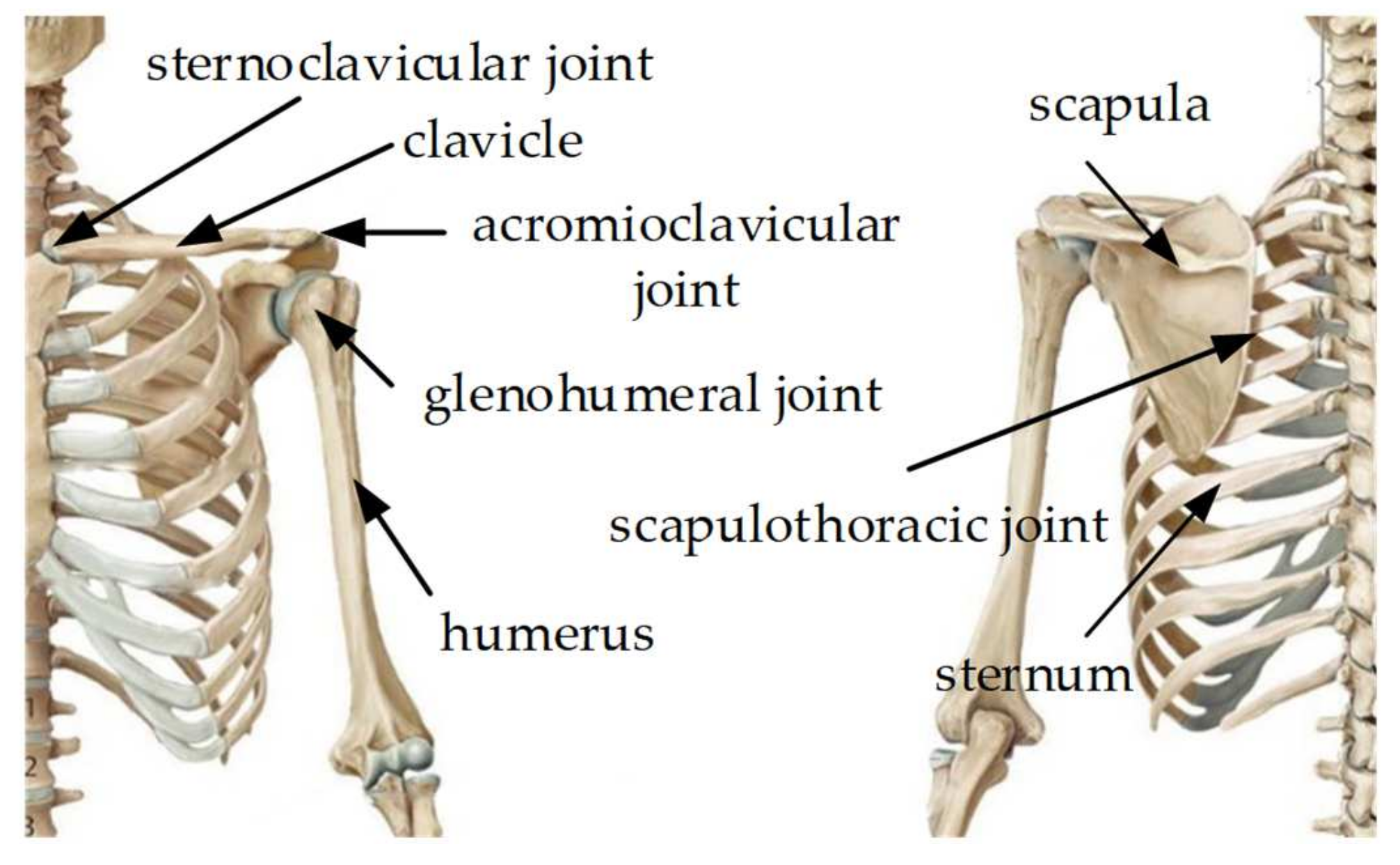
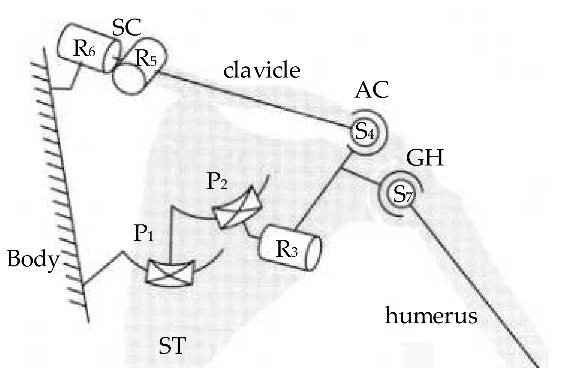
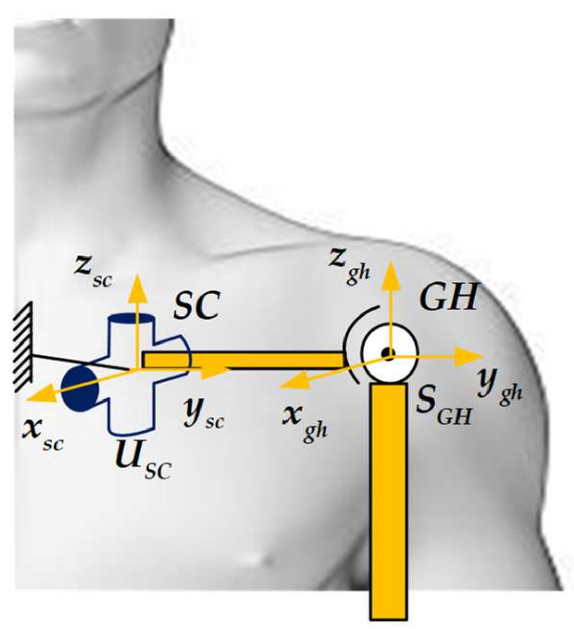
2.1. Human Upper Limb Anatomical Structure and Equivalent Mechanism Model

Broadly speaking, the shoulder joint is complex and involves the glenohumeral joint, acromioclavicular joint, sternoclavicular joint and scapular-chest wall joints [28] as shown in Figure 1. These joints coordinate and cooperate to complete a complex and flexible shoulder movement.
The glenohumeral joint (GH) is the main joint in the shoulder joint. The GH is composed of the ball and socket joint between the humeral head and the scapular glenoid [29]. The acromioclavicular joint (AC) is composed of the acromion end surface of the scapula and the end surface of the clavicle acromion joint [29]. The sternoclavicular joint (SC) is composed of the clavicle end face of the sternum and the clavicle notch of the sternum stem [30]. The scapulothoracic joint (ST) is a junction point between the front of the scapula and the back of the rib cage. The motion form of each subdivision joint of the scapula belt is shown in Figure 2.
Each joint in the shoulder joint is equivalent to the kinematic pair in the mechanism, in which the AC has 3-DOF and is equivalent to the ball pair S4. The SC has 3-DOF; however, its backward rotation is small, and it is less involved in the overall joint movement. Therefore, the SC is simplified to form Hooke’s hinge with 2 DOF, R5, R6. The ST has 3-DOF, which can be simplified to two translation pairs, P1, P2 and a rotating pair, R3. The GH is a typical ball and socket joint, which is equivalent to a ball joint, S7. Therefore, the equivalent mechanism model of the anatomical structure of the scapula belt is shown in Figure 3. According to the Grubler–Kutzbach formula, the DOF of the parallel mechanism can be calculated as shown below.
F = λ n g 1 + i = 1 g f i = 6 6 6 1 + 8 = 2
where F is the DOF of the mechanism; λ is the number of DOFs the mechanism rods should have in space, generally 6; n is the number of mechanism rods; g is the number of motion pairs in the mechanism; fi is the number of DOFs of the i-th motion pair.
Since the translation trajectory of P1, P2 is an arc trajectory centred on the axis of rotation of R5 and R6, R5 and R6 can be regarded as a virtual constraint of the translation pair of P1, P2. Since the R3 rotation axis is very close to the centre of the GH ball pair S7, it is usually regarded as the same position, so the R3 rotation effect overlaps the S7 motion range. Biologically, because GH S7 has a certain range of motion, scapula uprotation/downrotation R3 can be used to compensate for the range of motion of the GH. Therefore, the equivalent mechanism model of the scapula belt can be simplified to a 5-DOF tandem mechanism, as shown in Figure 4.
In addition, upper limb exercises also include elbow joint flexion/extension, forearm pronation/supination, wrist joint dorsiflexion/palm flexion and radial flexion/ulnar flexion. Since the rotation axes of the 2-DOF of the wrist joint intersect, to reduce the design difficulty and production cost, the wrist joint of the rehabilitation robot adopts a single DOF, and the wrist joints are separately trained with different DOFs. Thus far, the equivalent mechanism model of the human upper limb can be established as a 9-DOF series motion model, as shown in Figure 5.
To facilitate the measurement of upper limb kinematic information and unified clinical application communication, the International Society of Biomechanics (ISB) developed a description method for upper limb movement [31]. The lifting surface angle α, uplift angle within the uplift plane β and internal rotation/external rotation angle γ are used to describe the current position of the upper arm relative to the GH joint. Klopcar [32] et al. used experiments and synthetically obtained the kinematic coupling relationship between the SC and the GH rotation angle. The functional relationship between the uplift angle β and the forward/retracted angle φfb and the uplift/sink angle φud of the SC is:
ϕ f b = 0.35 β , 0 ° ,   0.22 β + 15.4 ° , β 0 ° 0 ° β 70 ° β > 70 °
ϕ u d = 0.3 β , 0 ° ,   0.36 β 10.8 ° , β < 0 ° 0 ° β 30 ° β > 30 °

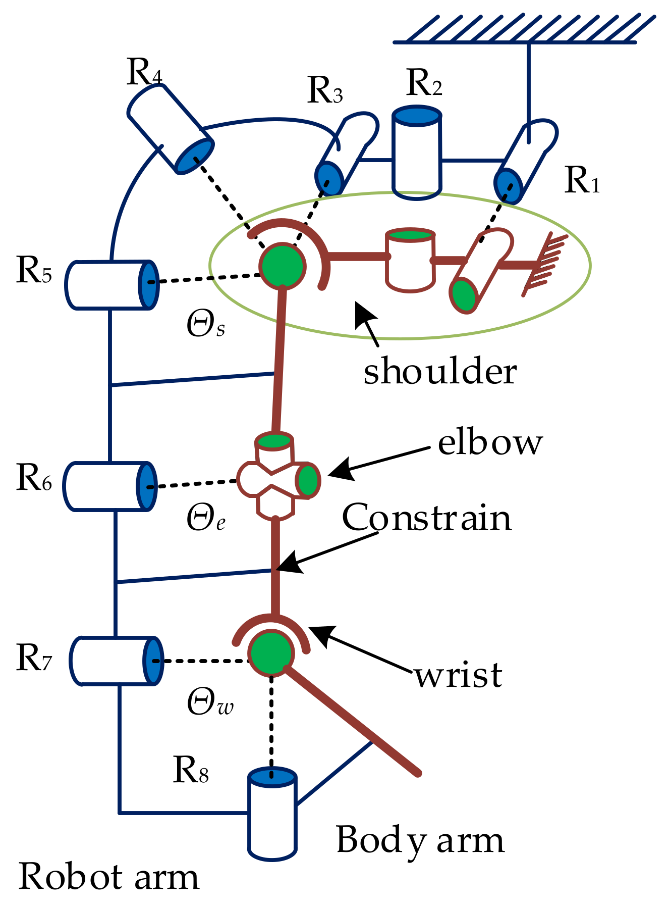
2.2. Human–Machine Compatible Configuration Design of the Shoulder Joint

In an ideal state, the human body’s affected limb and mechanical arm form a closed kinematic chain [33]. Based on the Hunt formula [34], the DOF of the human–machine closed chain is calculated by Equation (4).
F = i = 1 n f i d × l
where F is the number of DOFs, n is the number of joints in the closed-chain system, fi is the number of DOFs of the joints, d is the dimension of the motion space of the member (generally taken as 6), and l is the number of closed loops.
In the human generalized shoulder joint, the AC, SC, ST and GH are simplified into one joint; the motion of the joint is three rotations; the drift of the GH movement axis is in space. According to the above, the corresponding mechanical arm has 5 DOFs at the shoulder joint. Then, a closed chain of the man–machine can be formed, including the closed chain of the shoulder joint Θs. By analogy, the elbow joint closed-chain Θe and the wrist joint closed-chain Θw are shown in Figure 6.
For mechanisms with unknown DOFs, Formula (4) is expressed as Formula (5).
F = f k + f u k d × l = i = 1 j f i + m = j + 1 n f m d × l
where fk and fuk are the DOFs of the known joints and the unknown joints of the human–machine closed chain, respectively, and j is the number of known joints in the closed chain.
According to Figure 4, a simplified, equivalent mechanism model can be divided into three human–machine closed chains, namely, Θs, Θse and Θsew. It is known that there are five DOFs of the human shoulder joint and five DOFs of the shoulder joint mechanism in the closed shoulder joint chain, so fk,s = 10. The same is true for fk,se = 13 and fk,sew = 18. The institutional design requirements are Fs = 5, Fse = 6 and Fsew = 8. Therefore, the unknown joint DOFs fuk,s, fuk,se and fuk,sew can be solved by Equation (5).
f u k , s = F s f k , s + d × l = 5 10 + 6 = 1
f u k , s e = F s e f k , s e + d ×   l = 6 13 + 12 = 5
f u k , s e w = F s e w f k , s e w + d × l = 8 18 + 18 = 8
From Equations (6) and (7), it can be seen that the shoulder joint closed loop chain introduces at least one passive DOF and the shoulder–elbow closed loop chain must introduce five passive DOFs, and Equation (8) shows that the overall human–machine closed chain must introduce eight passive DOFs. Due to the introduction of five or more passive degrees of freedom in the independent closed-loop chain, the passive drive chain is longer. The efficiency of energy and force transmission will be lower [35], the overall robot control will become particularly complicated, the passive DOF introduced in the closed chain of the manipulator wrist joint is first eliminated, and the spatial flexibility of the handle is reduced to achieve better manipulator control accuracy. Second, the human–machine closed chain of the shoulder joint Θs is required to be the just-constrained subsystem, and the passive DOF introduced by the human–machine closed chain should be:
f s = 1 ; f e = 4 ;   f w = 0
According to the generalized shoulder joint motion mechanism model, the main motion of the GH will be realized by the RRR mechanism with three rotation axes converging at one point, and there are many combinations to meet the configuration of the auxiliary motion branch chain. The combination methods are shown in Table 1.
The ball pair is difficult to process in engineering and cannot be used as an active drive to realize the auxiliary movement of the shoulder joint, and the range of the angle of movement is small, which cannot meet the range of movement of the upper limbs; for the convenience of engineering, Hooke hinge U and cylinder pair S are usually replaced by two rotating pairs R or one rotating pair R and moving pair P. Therefore, only the R or P combination mechanism configuration in the table is selected.

3. Kinematics Analysis of the Equivalent Mechanism

Referring to the configuration and joint distribution of mature arm II and harmony robots at home and abroad, and considering the factors that the passive branch chain is as short as possible and the motion load of active joint is as small as possible, 2Pa1P3Ra and 5Ra1P were selected as mechanical arm shoulder joint mechanism configurations with engineering application value, where Pa represents the active mobile pair, P represents the passive mobile pair and Ra represents the active mobile pair.

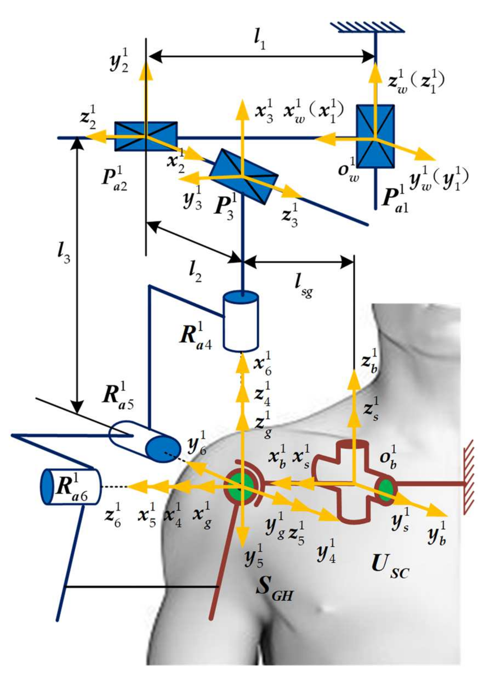
3.1. 2Pa1P3Ra Shoulder Joint Mechanism Configuration

The configuration of 2Pa1P3Ra is shown in Figure 7. In the figure, R a 4 1 , R a 5 1 and R a 6 1 are the three active rotation pairs for the main motion. The three rotational axes are orthogonal to each other. P a 1 1 and P a 2 1 are the two active moving pairs, and the moving axes are orthogonal to each other, which can realize the upward/sinking movement of the GH motion axis in the coronal plane of the human body. P 3 1 is the passive moving pair, which is orthogonal to P a 1 1 , P a 2 1 and each other, and the passive sliding axis can realize forward/backward movement of the GH motion axis in the sagittal plane of the human body and can combine with P a 1 1 , P a 2 1 to realize the tracking of the GH motion axis at any position in space, thereby improving the human–machine compatibility.
A fixed coordinate system O b 1 x b 1 y b 1 z b 1 is established in the SC USC, a human shoulder joint equivalent mechanism connection system O s 1 x s 1 y s 1 z s 1 is established in the GH SGH, and a connection system O g 1 x g 1 y g 1 z g 1 is established at the same time here. The coordinate axes of the two coordinate systems coincide in the initial pose. A local coordinate system O w 1 x w 1 y w 1 z w 1 is established on the frame of the robot, and a joint coordinate system O i 1 x i 1 y i 1 z i 1   ( i = 1 , 2 , , 6 ) is established for each movement pair of the generalized shoulder joint mechanism, where the R a 4 1 , R a 5 1 and R a 6 1 motion axes intersect at the axis of the shoulder joint. In the initial configuration of the mechanical arm, the coordinate origin O i 1   ( i = 4 , 5 , 6 ) coincides with the origin O s 1 of the GH joint coordinate system. The origin O w 1 of the gantry fixed coordinate system coincides with the movement centre O 1 1 of the mobile pair P a 1 1 , as shown in Figure 7. The origin O w 1 of the frame local fixed coordinate system in the human body fixed coordinate system O b 1 x b 1 y b 1 z b 1 is X w 1 , Y w 1 , Z w 1 .
According to the pose transformation matrix, the pose transformation matrix T b 6 1 of the end coordinate system O 6 1 x 6 1 y 6 1 z 6 1   of the mechanical arm branch chain relative to the human body fixed coordinate system O b 1 x b 1 y b 1 z b 1 is:
T b 6 1 = T b w 1 T w 1 1 T 1 2 1 T 2 3 1 T 4 5 1 T 5 6 1 = n 6 x 1 s 6 x 1 a 6 x 1 X 6 1 n 6 y 1 s 6 y 1 a 6 y 1 Y 6 1 n 6 z 1 s 6 z 1 a 6 z 1 Z 6 1 0 0 0 1
where T b w 1 , T w 1 1 and T i i + 1 1   ( i = 1 , 2 , 3 , 4 , 5 ) are the pose transformation matrices between adjacent coordinate systems; n 6 1 = n 6 x 1 , n 6 y 1 , n 6 z 1 T , s 6 1 = s 6 x 1 , s 6 y 1 , s 6 z 1 T and a 6 1 = a 6 x 1 , a 6 y 1 , a 6 z 1 T are the direction vectors of each axis end coordinate system O 6 1 x 6 1 y 6 1 z 6 1   in O b 1 x b 1 y b 1 z b 1 ; P 6 1 = X 6 1 , Y 6 1 , Z 6 1 T is the position vector of the origin O 6 1 .
For the branch chain of the human shoulder joint equivalent mechanism, the pose transformation matrix T b g 1 of the mechanism end coordinate system O g 1 x g 1 y g 1 z g 1 relative to the human body fixed coordinate system O b 1 x b 1 y b 1 z b 1 can also be obtained as:
T b g 1 = T b s 1 T s g 1 = n g x 1 s g x 1 a g x 1 X g 1 n g y 1 s g y 1 a g y 1 Y g 1 n g z 1 s g z 1 a g z 1 Z g 1 0 0 0 1
Since the end coordinate systems of the two branch chains are closed and the pose is always the same, Equations (10) and (11) are simultaneously solved, so the kinematics constraint equation of the man–machine closed chain can be established as:
X 6 1 = X g 1 Y 6 1 = Y g 1 Z 6 1 = Z g 1 n 6 x 1 a g x 1 + n 6 y 1 a g y 1 + n 6 z 1 a g z 1 = 0 n 6 x 1 s g x 1 + n 6 y 1 s g y 1 + n 6 z 1 s g z 1 = 0 a g x 1 s 6 x 1 + a g y 1 s 6 y 1 + a g z 1 s 6 z 1 = 0
Deriving both sides of Equation (12) with respect to time t and sorting yields:
α ˙ φ ˙ γ ˙ = J 11 1 J 12 1 J 13 1 J 21 1 J 22 1 J 23 1 J 31 1 J 32 1 J 33 1 θ ˙ 4 1 θ ˙ 5 1 θ ˙ 6 1 = J 1 θ ˙ 4 1 θ ˙ 5 1 θ ˙ 6 1
where θ ˙ 4 1 , θ ˙ 5 1 and θ ˙ 6 1 are the rotation speeds of the three rotation pairs R a 4 1 , R a 5 1 and R a 6 1 in 2Pa1P3Ra, respectively, and J i j 1   ( i , j = 1 , 2 , 3 ) is the polynomial of the human body rotation angle parameters α, β, γ.

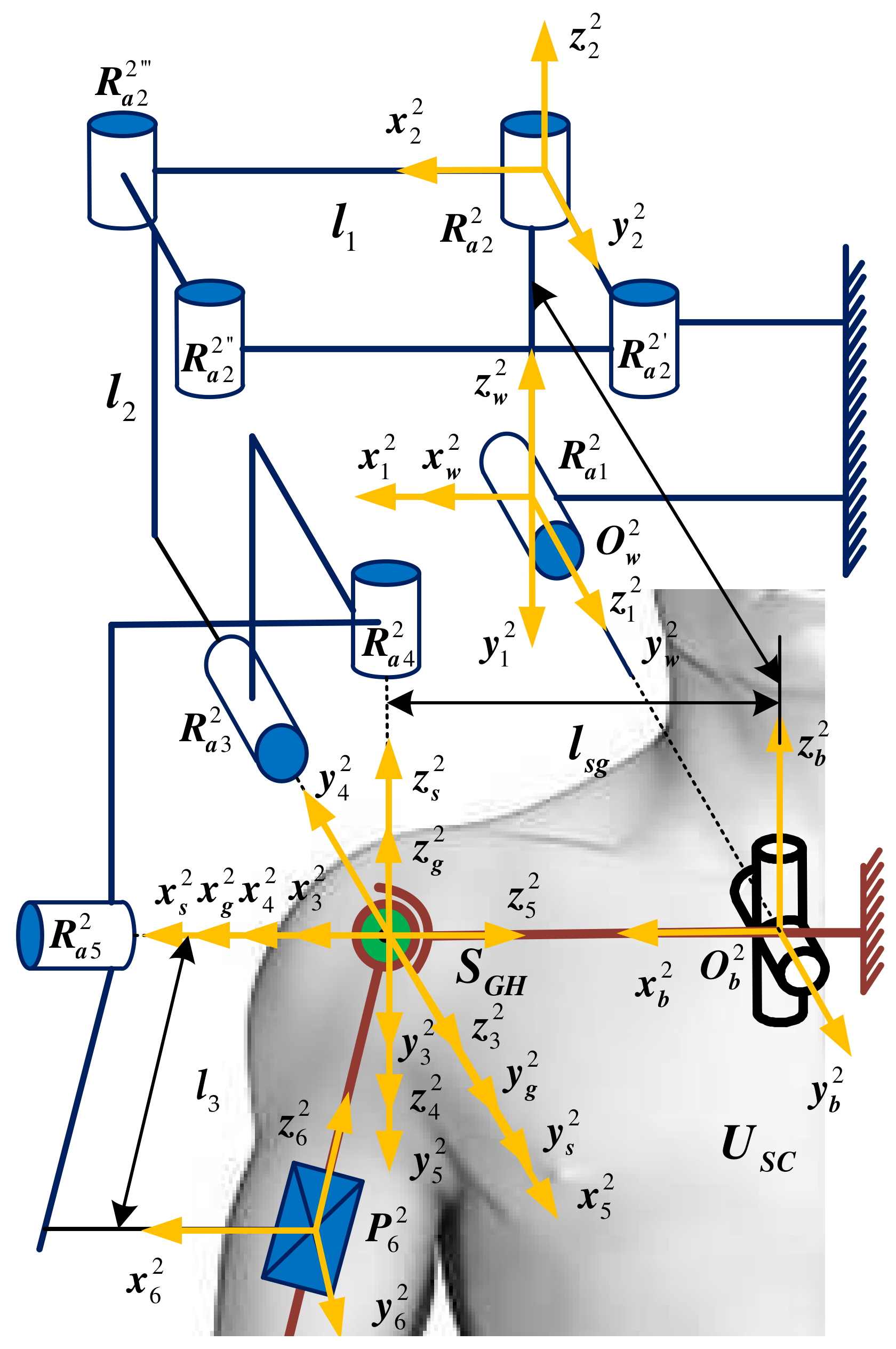
3.2. 5Ra1P Shoulder Joint Mechanism Configuration

The configuration of 5Ra1P is shown in Figure 8. In the figure, R a 3 2 , R a 4 2 and R a 5 2 are the three active rotation pairs of the main motion, and the three rotation axes are orthogonal to each other. R a 1 2 , R a 2 2 are two active rotation pairs, and the rotation axes are orthogonal to each other, where R 2 2 , R 2 2 , R 2 2 and R a 2 2 constitute a parallelogram structure, which translates a rotating pair in the human body USC to the back of the human body, which is convenient for installation and control in engineering. P 6 2 is the passive moving pair, which is directly connected to the upper limb.
A fixed coordinate system O b 2 x b 2 y b 2 z b 2 is established on the SC USC, a local fixed coordinate system O w 2 x w 2 y w 2 z w 2 is established on the frame, and a connected coordinate system O i 2 x i 2 y i 2 z i 2   ( i = 1 , 2 , , 6 ) is established for each movement pair of the generalized shoulder joint mechanism, where the R a 4 2 , R a 5 2 and R a 6 2 motion axes intersect the machine at the axis of the arm shoulder joint. In the initial configuration of the mechanical arm, the coordinate origin O i 2   ( i = 4 , 5 , 6 ) coincides with the origin O s 2 of the GH joint coordinate system. The origin O w 2 of the gantry coordinate system coincides with the movement centre O 1 2 of the rotating pair R a 1 2 , as shown in Figure 8. The origin O w 2 of the frame local fixed coordinate system is X w 2 , Y w 2 , Z w 2 in the human body fixed coordinate system O b 2 x b 2 y b 2 z b 2 .
According to the pose transformation matrix, the pose transformation matrix T b 6 2 of the end coordinate system O 6 2 x 6 2 y 6 2 z 6 2   of the mechanical arm branch chain relative to the fixed coordinate system O b 2 x b 2 y b 2 z b 2 of the human body is:
T b 6 2 = T b w 2 T w 1 2 T 1 2 2 T 2 3 2 T 4 5 2 T 5 6 2 = n 6 x 2 s 6 x 2 a 6 x 2 X 6 2 n 6 y 2 s 6 y 2 a 6 y 2 Y 6 2 n 6 z 2 s 6 z 2 a 6 z 2 Z 6 2 0 0 0 1
For the branch chain of the human shoulder joint equivalent mechanism, the end coordinate system of the mechanism can also be obtained, and the pose transformation matrix T b g 2 of O g 2 x g 2 y g 2 z g 2 relative to the fixed coordinate system of the human body O b 2 x b 2 y b 2 z b 2 is:
T b g 2 = T b s 2 T s g 2 = n g x 2 s g x 2 a g x 2 X g 2 n g y 2 s g y 2 a g y 2 Y g 2 n g z 2 s g z 2 a g z 2 Z g 2 0 0 0 1
where T b s 2 is the pose transformation matrix between adjacent coordinate systems, and T b g 2 is the pose transformation matrix of the new coordinate system O g 2 x g 2 y g 2 z g 2 after the end coordinate system of the mechanism is rotated in space. n g 2 = n g x 2 , n g y 2 , n g z 2 T , s g 2 = s g x 2 , s g y 2 , s g z 2 T and a g 2 = a g x 2 , a g y 2 , a g z 2 T are the direction vectors of each axis end coordinate system a g 2 = a g x 2 , a g y 2 , a g z 2 T in O b 2 x b 2 y b 2 z b 2 , and P g 2 = X g 2 , Y g 2 , Z g 2 T is the position vector of the origin O g 2 .
Simultaneous to Equations (14) and (15), the kinematics constraint equation of the man–machine closed chain can be established as:
X 6 2 = X g 2 Y 6 2 = Y g 2 Z 6 2 = Z g 2 n 6 x 2 s g x 2 + n 6 y 2 s g y 2 + n 6 z 2 s g z 2 = 0 n 6 x 2 a g x 2 + n 6 y 2 a g y 2 + n 6 z 2 a g z 2 = 0 s g x 2 a g x 2 + s g y 2 a g y 2 + s g z 2 a g z 2 = 0
Deriving both sides of Equation (16) with respect to time t and sorting yields:
α ˙ φ ˙ γ ˙ = J 11 2 J 12 2 J 13 2 J 21 2 J 22 2 J 23 2 J 31 2 J 32 2 J 33 2 θ ˙ 3 2 θ ˙ 4 2 θ ˙ 5 2 = J 2 θ ˙ 3 2 θ ˙ 4 2 θ ˙ 5 2
where θ ˙ 3 2 , θ ˙ 4 2 and θ ˙ 5 2 are the rotational angular speeds of the three rotating R a 3 2 , R a 4 2 and R a 5 2 in 5Ra1P, respectively, and J i j 2   ( i , j = 1 , 2 , 3 ) are the terms of the human body’s rotational angle parameters α, β, γ.

4. Comprehensive Kinematic Performance Analysis of the Shoulder Joint Configuration

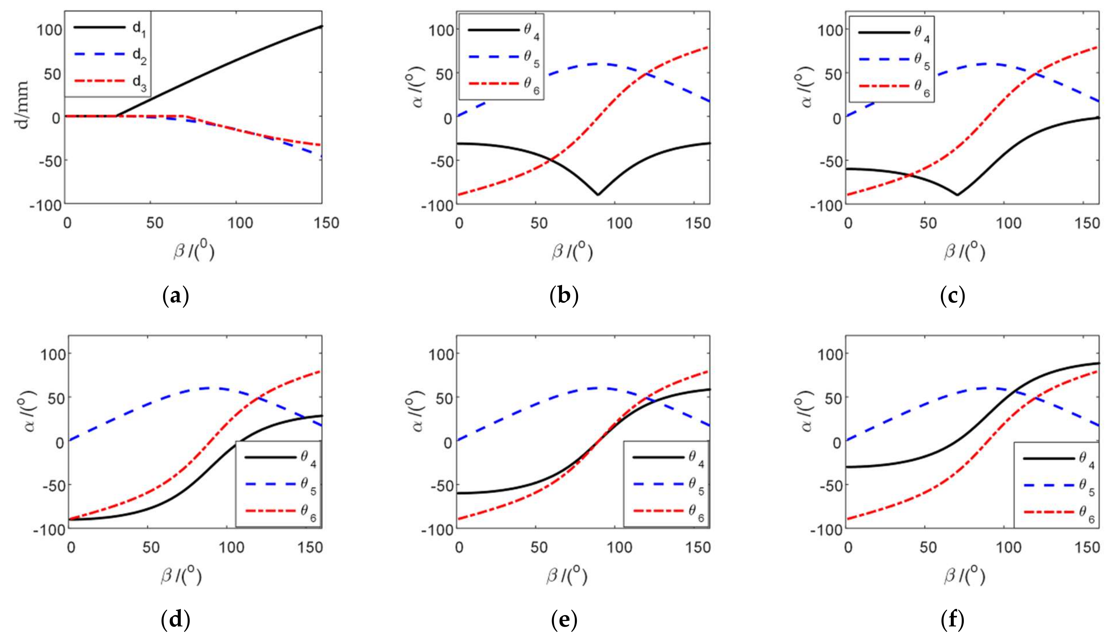
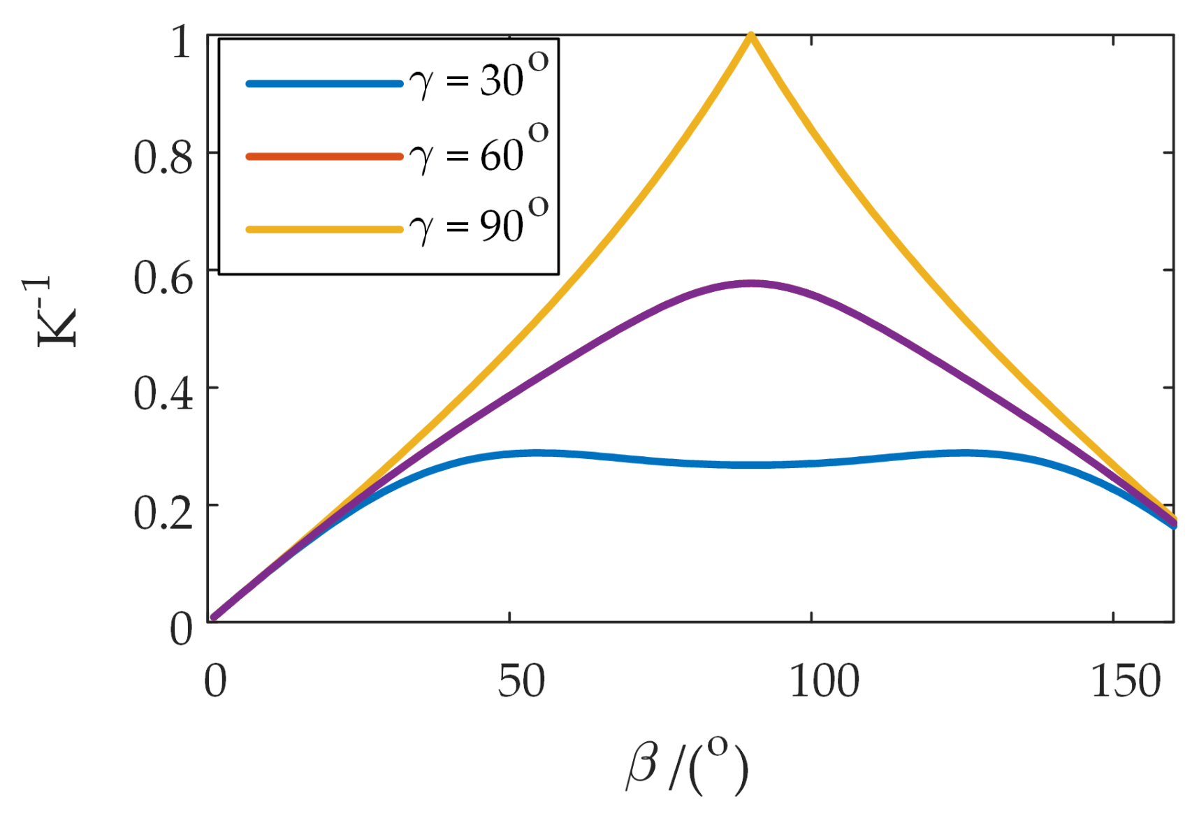
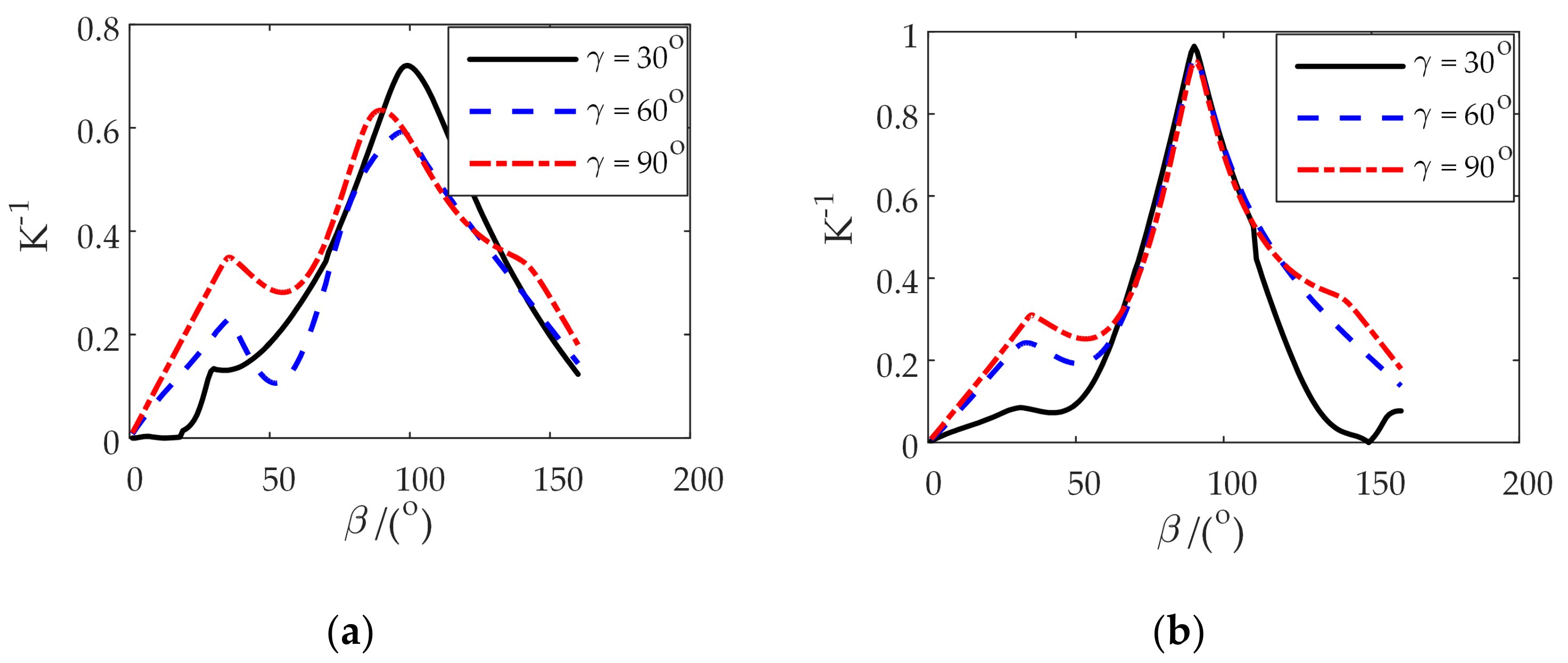
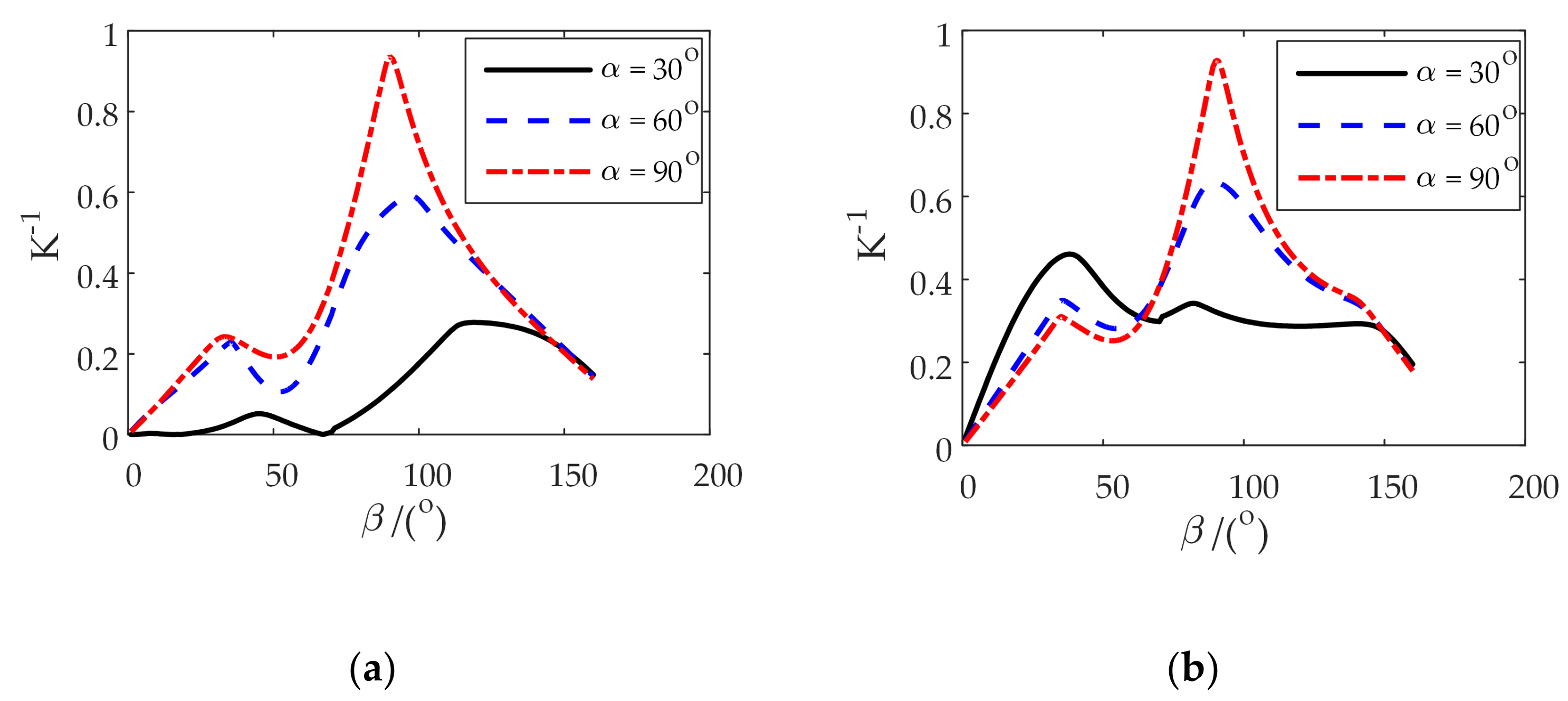
4.1. Inverse Kinematic Solution and Flexibility Analysis of Two Configurations

Referring to the size of the Chinese adult human body (GB/T10000-1988) [36] and combining the physical drive module size of two different configurations, the dimensions to be used are shown in Table 2.
At the same time, the patient’s upper arm lift angle range is set during the rehabilitation robot-assisted movement process as 0°~150°. The internal rotation/external rotation angle of the upper arm is set to γ = 30°, and the upper arm’s natural sag position is set as the lift angle β = 0°. In other lifting planes, this configuration is also selected as the initial lifting angle to determine the initial movement posture in each lifting plane.
Combining the size parameters listed in Table 2 and the inverse solution method of human–machine closed-chain kinematics given above, when the upper arm of the human body is lifted in the 0°, 30°, 60°, 90° and 120° lifting planes and the relationship between the turning angle θ i 1 ( i = 4 , 5 , 6 ) of the 2Pa1P3Ra turning pair R i 1 ( i = 4 , 5 , 6 ) and the lifting angle β are shown in Figure 9b–f.
It can be seen from Figure 9 that when the upper arm performs a lifting motion in different lifting planes, then the rotational angle θ i 1 ( i = 4 , 5 , 6 ) of each joint of the mechanical arm moves smoothly, and the corresponding rotational angle changes similarly in different lifting planes. Among them, θ4 and θ6 increase with the elevation of the lift angle β; θ5 first increases and then decreases, and in different lift planes, the change trend and movement range of θ6 and θ5 remain unchanged. θ4 continuously increases the initial change angle as the lift angle increases. The change in the movement pair follows the piecewise function of the shoulder blade belt and the lift angle, showing the same changing law, and the movement distance changes smoothly.
The relationship between the moving pair R i 2 ( i = 1 , 2 ) of the 5Ra1P configuration and the lift angle β is shown in Figure 10a. The relationship between the turning angle θ i 2 ( i = 3 , 4 , 5 ) of the turning pair R i 2 ( i = 3 , 4 , 5 ) and the lifting angle β is shown in Figure 10b–f.
It can be seen from Figure 10 that when the upper arm performs a lifting motion in different lifting planes, the rotation angles of each joint of the manipulator arm move smoothly, and the corresponding rotation angles move similarly in different lifting surfaces. The changes in θ1 and θ2 follow the piecewise function of the scapula belt and the lift angle, respectively, showing the same change law, and the rotation angle changes smoothly. Among them, θ3 and θ4 decrease with increasing β, while θ5 first increases and then decreases. In different uplift planes, the changing trend and range of motion of θ3 remain unchanged, which is closely related to the range of β. θ4 continuously increases the initial change amplitude as the lift angle increases.
The singularity σ of the mechanical arm Jacobi qualitatively describes the dexterity and performance of the mechanical arm [37]. At present, there are many quantitative indexes related to Jacobian singular value to reflect the dexterity and kinematic performance of the manipulator. Rojas uses the reciprocal of the condition number of the Jacobian matrix as an evaluation index to judge the dexterity of the mechanism, which is faster and clearer. The relationship between the condition number and the singular value of the Jacobian matrix is:
K J 1 = σ min / σ max
where σmin and σmax are the smallest and largest singular values of J(q), respectively.
The relationship curve between the reciprocal of the condition number K J 1 1 and the lifting angle β are compared when the two different configurations of the mechanism move in the same lifting surface, as shown in Figure 11. It can be seen that K J 1 1 of 2Pa1P3Ra is less affected by the change in the lifting surface angle and first increases and then decreases as β increases. As the internal rotation/external rotation angle γ increases, the overall movement flexibility of 2Pa1P3Ra improves. The configuration reaches a maximum value at β = 90° and γ = 90°, K J 1 1 = 1 , which means that the mechanism has reached isotropy at this time.
Figure 12 shows the relationship between K J 2 1 of the Jacobian matrix of 5Ra1P and the change in the lift angle β. It is observed that in the same uplift surface, as β increases, K J 2 1 first increases and then decreases and then continues to increase. When β = 90°, K J 2 1 reaches its maximum value and then falls. The curve trend shows that the mechanism has the best movement flexibility when β = 90°. In the same uplift surface, comparing different internal rotation/external rotation angles γ, the change trend of K J 2 1 with β is similar, and the larger the γ, the overall value of K J 2 1 increases; however, when 60° < β < 120°, K J 2 1 following γ, the range of change is small.
Figure 13 shows the relationship between K J 2 1 and the uplift angle β and the uplift surface angle α for 5Ra1P under a specific internal rotation/external rotation angle γ = 60°,90°. The change trend of K J 2 1 with β is similar to that in Figure 12. The change range of K J 2 1 following α is larger than that following γ. In the case of the same γ, an increase in α will cause an increase in K J 2 1 , which improves the movement flexibility of the mechanism.
Comparing Figure 11 to Figure 13, the lift angle α = 90° and the internal rotation/external rotation angle γ = 60° are taken as the comprehensive performance evaluation poses of 2Pa1P3Ra and 5Ra1P. Figure 14 shows the comparison of the reciprocal change curves of the condition number k−1 of the two manipulator shoulder joint configurations under the comprehensive performance evaluation position. As seen in Figure 14, when 40° < β < 70°, the movement flexibility of 2Pa1P3Ra is better than that of 5Ra1P. When β is at other angles, the movement flexibility of 5Ra1P is better than that of 2Pa1P3Ra, and K J 1 1 of 2Pa1P3Ra does not exceed 0.6. Compared with 5Ra1P, the movement flexibility is at a disadvantage.

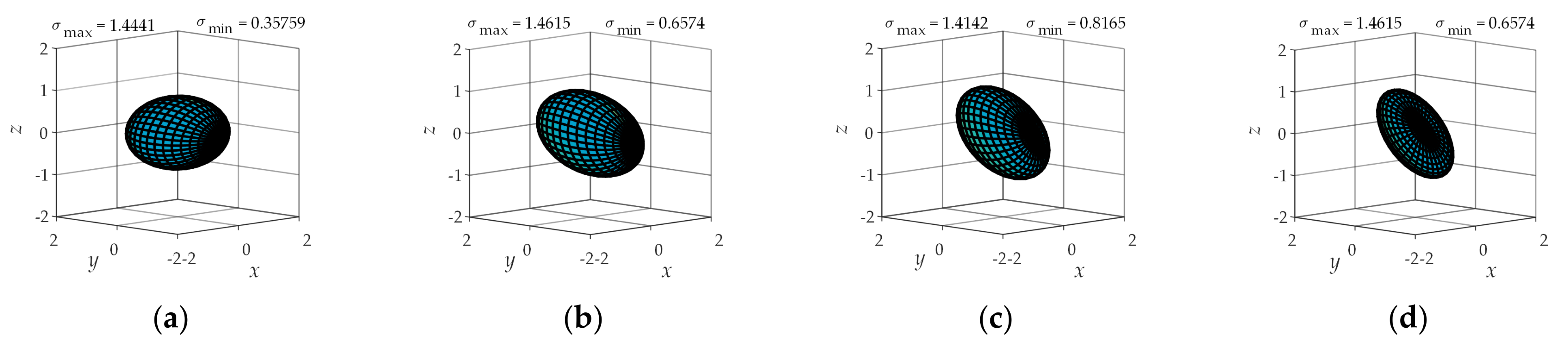
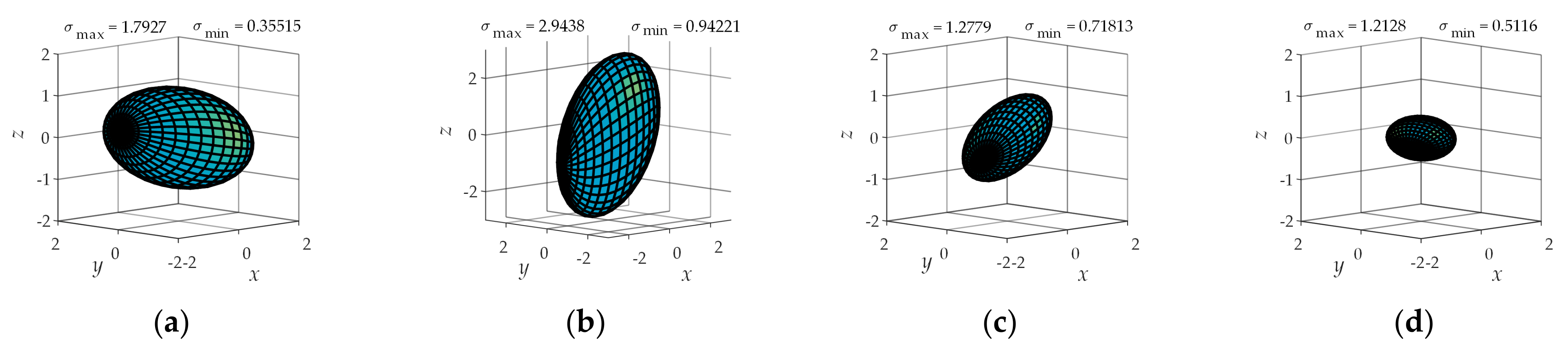
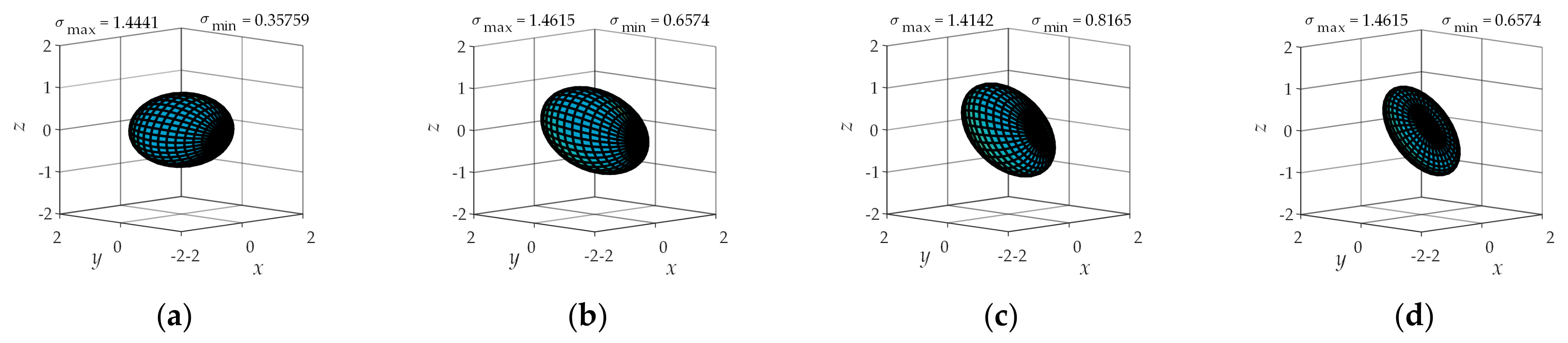
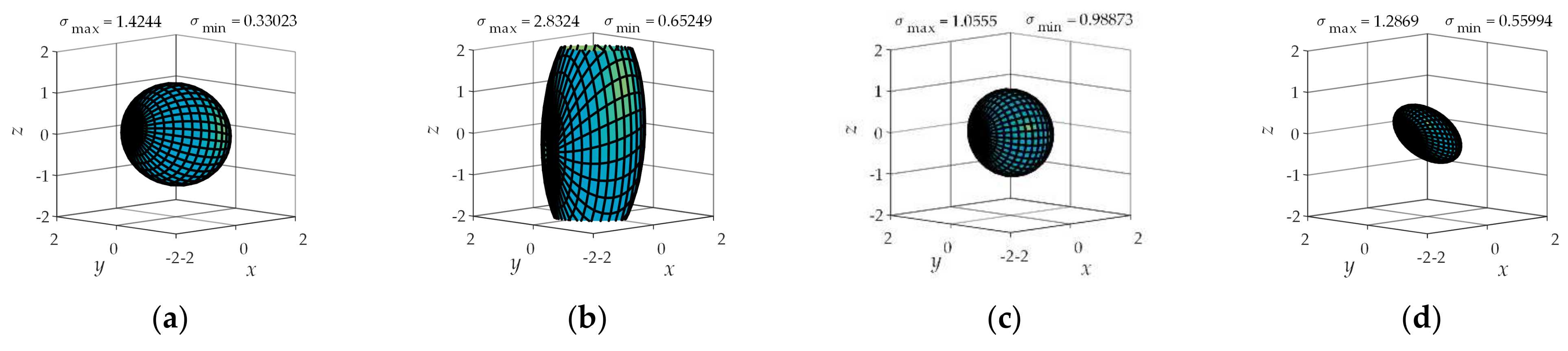
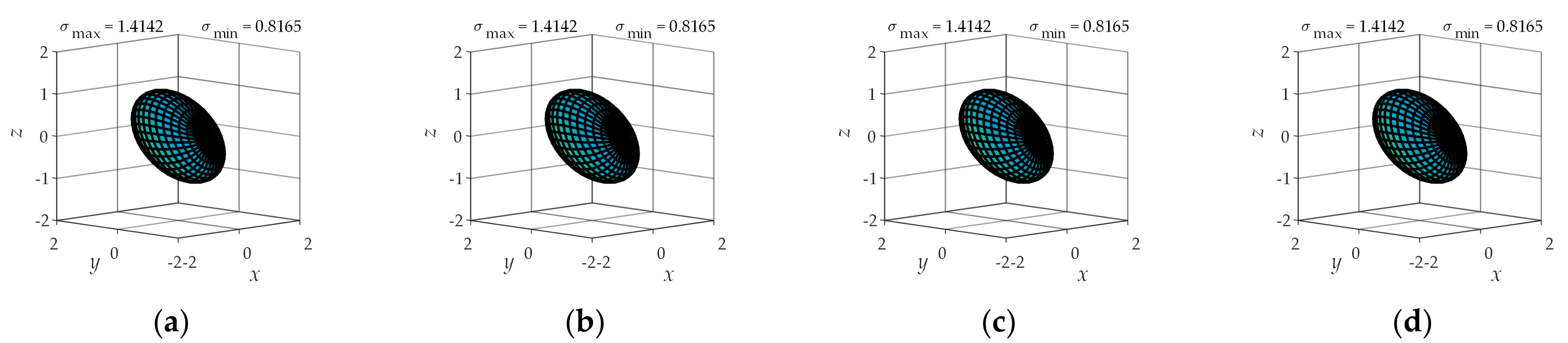
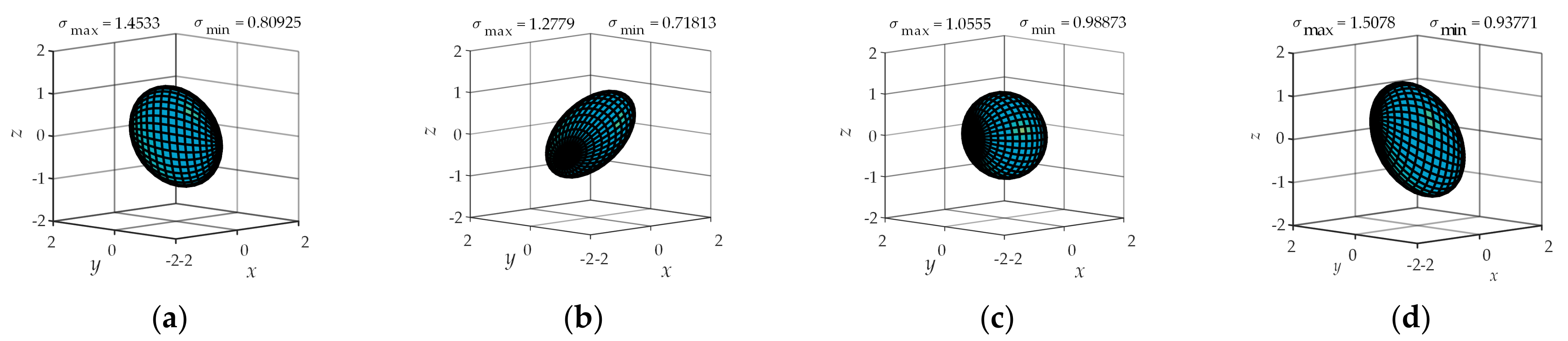
4.2. Operational Ellipsoid Analysis

The reciprocal of the condition number of the Jacobian matrix can be used to judge whether the current posture of the mechanical arm is singular. If the condition number is large, then the current Jacobian matrix is ill conditioned. However, for some actions, the reciprocal of the condition number is too large and does not affect the normal operation of the mechanism, so the concept of operability is proposed. Yoshikawa [38] defines operability:
m = det ( J J T ) = λ 1 λ 2 λ n = σ 1 σ 2 σ n
where λi (i = 1,2,···n) is the eigenvalue of matrix JJT, and σi (i = 1,2,···n) is the singular value of Jacobian matrix J.
To compare the isotropic motion capabilities of the two mechanisms in different poses, the operability ellipsoids of the two mechanisms are compared at different positions on the coronal, sagittal and horizontal planes of the human body.
Figure 15 and Figure 16 show the operability ellipsoids with 2Pa1P3Ra and 5Ra1P in the lift plane α = 30° of the human body at positions β = 30°, 60°, 90°, 120°. Through comparison, when β = 90°, the operable ellipsoids of the two configurations are closest to the sphere. At this time, 5Ra1P has better isotropic movement ability in all directions than 2Pa1P3Ra.
In the lifting plane α = 30°, when the angles change as β = 30°, 60°, 90°, 120°, the operability ellipsoids of the two configurations have similar changes in shape, indicating that the two have the same movement flexibility in α = 30°, and the same-sex athletic ability is the same in the angular position.
Figure 17 and Figure 18 show the operability ellipsoids with 2Pa1P3Ra and 5Ra1P, respectively, in the lift plane α = 90° (sagittal plane) of the human body at position β = 30°, 60°, 90°, 120°. Through comparison, it can be seen that when β = 90°, the operable ellipsoid of the two configurations is closest to the sphere, and the operability ellipsoid of 5Ra1P is very close to the sphere compared to 2Pa1P3Ra. In this lift plane, the isotropic movement ability in all directions is better.
In the sagittal plane, when the lift angle changes at β = 30°, 90°, 120°, the change in the operability ellipsoid of 5Ra1P is smaller than that of 2Pa1P3Ra. When β = 60°, the change in the operability ellipsoid of 5Ra1P changes more than 2Pa1P3Ra. However, the overall performance shows that 5Ra1P has slightly better movement flexibility in the α = 30° lifting plane and has slightly better single-sex movement ability under the corresponding lifting angle posture.
It can be seen from Figure 19 and Figure 20 that 2Pa1P3Ra has the same operability ellipsoid in the horizontal plane, indicating that the motion performance of the mechanism configuration corresponding to different lift angles on the horizontal plane remains unchanged. In the horizontal plane, when the lifting surface angle changes at α = 30°, 90°, 120°, the overall operability of the5Ra1P ellipsoid is closer to a spherical shape than 2Pa1P3Ra. The overall performance shows that 5Ra1P has better movement flexibility in the horizontal plane, and the same-sex sports ability is stronger in the corresponding lift angle pose.
The changes in the operability ellipsoids of the 2Pa1P3Ra and 5Ra1P in four different forms on three planes are summarized in Table 3. A comparison index S is proposed. S is the D-value between the sum of the changes in the operability ellipsoids of two mechanisms. It can be seen from Table 3 that on the 30° coronal plane, 2Pa1P3Ra is better than 5Ra1P; on the other two sides, 5Ra1P is better than 2Pa1P3Ra.

5. Experiment

The kinematic analysis, inverse kinematics solution and kinematic performance analysis of the two configuration design schemes show that the kinematic performance of 5Ra1P is better, so a prototype of the 5Ra1P configuration was built, as shown in Figure 21. The prototype has a generalized shoulder joint, which can realize 5-DOF movement at the shoulder joint; the elbow joint, forearm joint and wrist joint each have one active DOF.
Particularly, two passive DOFs are added to the forearm man–machine contact component, which are the freedom of rotation around the forearm axis and the freedom of movement in the axis direction, as shown in Figure 22. By setting four nylon rollers, the forearm support ring is fixed on the virtual circular track, the support ring is equipped with a linear guide and a slider, and the strap is internally fixed on the slider to realize the two passive DOFs of the forearm man–machine contact parts. A spring is added between the forearm support ring and the nylon roller support frame. Two identical compression springs are placed on both sides of the sliding block in the support ring. An elastic element is added to the mechanical structure of the passive pair to make the passive pair have a certain degree of flexibility during movement, relieving the uncertainty of exercise and the instability of exercise coordination. Friction was avoided between the support ring and the patient’s skin, discomfort was avoided, and the patient was restrained.
Due to the safety of patient movement, the prototype was designed with mechanical limits in structure. The rotational range of the shoulder 1 movement module is 0°~110°; the rotational range of the shoulder 2 movement module is −90°~30°; the rotational range of the shoulder 3 movement module is −60°~90°, in which the shoulder 1, shoulder 2 and shoulder 3 movement modules correspond to the three intersecting rotation axes of the shoulder joint in sequence so that the prototype can move along the maximum space boundary to realize several kinds of movement states of human upper limbs, as shown in Figure 23.

6. Conclusions

Based on the anatomical structure of the upper limbs of the human body, the shoulder joint ergonomic closed-chain Θs constrained and shoulder–elbow joint ergonomic closed-chain Θse under-constrained models are established. In the shoulder joint ergonomic closed chain, the mechanical arm has five active DOFs and one passive DOF, and the 2Pa1P3Ra and 5Ra1P generalized shoulder joint mechanism configuration combinations were selected with engineering application value to achieve kinematic compatibility with human upper limbs.
According to the kinematics analysis, the inverse kinematics solution, the reciprocal of the condition number, operability ellipsoid analysis and a comparison of the two configuration schemes, the results show that in the normal upper limb posture of the human body, the kinematics performances, such as the mobility flexibility and isotropic movement ability, of the 5Ra1P configuration are better than those of 2Pa1P3Ra, and this configuration was selected for prototype construction, which lays a theoretical foundation for the development of upper limb rehabilitation robots in the future.

Author Contributions

Methodology, H.W. and H.Y.; software, P.C. and Y.N.; validation, S.L.; formal analysis, H.Y.; writing—original draft preparation, P.C.; writing—review and editing, H.W., J.N. and H.Y.; project administration, H.W.; supervision, X.W. All authors have read and agreed to the published version of the manuscript.

Funding

This research was funded by National Key Research and Development Program of China, grant number 2019YFB1312500; National Natural Science Foundation of China, grant number U1913216; Hebei Provincial Key Research Projects, grant number 19211820D; Hebei Provincial Key Research Projects, grant number 20371801D; The Science and Technology (S&T) Program of Hebei under Grant 206Z1801G.

Institutional Review Board Statement

Not applicable.

Informed Consent Statement

Written informed consent has been obtained from the patient(s) to publish this paper.

Data Availability Statement

Data sharing is not applicable to this article.

Conflicts of Interest

The authors declare no conflict of interest.

References

  1. Dong, Q.; Guo, Q.; Luo, B.; Xu, Y. Expert consensus on post-stroke cognitive management. Chin. J. Stroke 2017, 12, 519–531. [Google Scholar]
  2. Cong, C.H.; Ya, Z.; Wei, W.L.; Teng, Y.Z. Prospects for intelligent rehabilitation techniques to treat motor dysfunction. Neural Regen. Res. 2021, 2, 264–269. [Google Scholar]
  3. Feigin, V.L.; Forouzanfar, M.H.; Krishnamurthi, R.; Mensah, G.A.; Connor, M.; Bennett, D.A.; Moran, A.E.; Sacco, R.L.; Anderson, L.; Truelsen, T. Global and regional burden of stroke during 1990–2010: Findings from the Global Burden of Disease Study 2010. Lancet 2014, 383, 245–255. [Google Scholar] [CrossRef]
  4. Li, X.; Tang, Z.M.; Wu, D.L.; Su, L.J.; Zheng, Y.D.; Chen, P.R.; Zhang, Y.W.; Dou, Z.L.; Li, K.; Hoseinbeyki, A. Analysis of the Positive Effect of Robot-Assisted Virtual Reality Technology on Rehabilitation of Motor Function and Nerve Function in Cerebral Stroke Patients. J. Med. Imaging Health Inform. 2021, 2, 595–600. [Google Scholar] [CrossRef]
  5. Chen, W.B. Human Upper Limb Kinematics Analysis and Humanoid Body Design and Movement Planning. Master’s Thesis, Huazhong University of Science and Technology, WuHan, China, 2012. [Google Scholar]
  6. Karduna, A.R.; McClure, P.W.; Michener, L.A. Scapular kinematics: Effects of alterning the Euler angle sequence of rotations. J. Biomech. 2000, 33, 1063–1068. [Google Scholar] [CrossRef]
  7. Borstad, J.D.; Ludewig, P.M. Comparison of scapular kinematics between elevation and lowering of the arm in the scapular plane. Clin. Biomech. 2002, 17, 650–659. [Google Scholar] [CrossRef]
  8. Fung, M.; Kato, S.; Barrance, P.J.; Elias, J.J.; McFarland, E.G.; Nobuhara, K.; Chao, E.Y. Scapular and clavicular kinematics during humeral elevation: A study with cadavers. Shoulder Elb. Surg. 2001, 10, 278–285. [Google Scholar] [CrossRef]
  9. McClure, P.W.; Michener, L.A.; Sennett, B.J.; Karduna, A.R. Direct 3-dimensional measurement of scapular kinematics during dynamic movements in vivo. Shoulder Elb. Surg. 2001, 10, 269–277. [Google Scholar] [CrossRef] [Green Version]
  10. Nef, T.; Guidali, M.; Riener, R. ARMinIII-arm therapy exoskeleton with an ergonomic shoulder actuation. Appl. Bionics Biomech. 2015, 6, 127–142. [Google Scholar] [CrossRef] [Green Version]
  11. Klamrothmarganska, V.; Blanco, J.; Campen, K. Three-dimensional, task-specific robot therapy of the arm after stroke: A multicentre, parallel-group randomisedtrial. Lancet Neurol. 2014, 13, 159–166. [Google Scholar] [CrossRef]
  12. Perry B, E.; Evans E, K.; Stokic, D.S. Weight compensation characteristics of Armeo Spring exoskeleton: Implications for clinical practice and research. J. Neuro Eng. Rehabil. 2017, 14, 14. [Google Scholar] [CrossRef] [Green Version]
  13. Yu, W.; Rosen, J. A novel linear PID controller for an upper limb exoskeleton. In Proceedings of the IEEE Conference on Decision and Control, Atlanta, GA, USA, 15–17 December 2010; pp. 3548–3553. [Google Scholar]
  14. Pignolo, L.; Lucca, L.F.; Basta, G.; Serra, S.; E Pugliese, M.; Sannita, W.G.; Dolce, G. A new treatment in the rehabilitation of the paretic upper limb after stroke: The ARAMIS prototype and treatment protocol. Annali dell’Istituto Superiore di Sanità 2016, 52, 301–308. [Google Scholar]
  15. Ball, S.J.; Brown, I.E.; Scott, S.H. Medarm: A rehabilitation robot with 5-DOF at the shoulder complex. In Proceedings of the IEEE/ASME International Conference on Advanced Intelligent Mechatronics, Zurich, Switzerland, 4–7 September 2007; pp. 1–6. [Google Scholar]
  16. Kim, B.; Deshpande, A.D. An upper-body rehabilitation exoskeleton Harmony with an anatomical shoulder mechanism: Design, modeling, control, and performance evaluation. Int. J. Robot. Res. 2017, 36, 414–435. [Google Scholar] [CrossRef]
  17. Otten, A.; Voort, C.; Stienen, A. Limpact: A hydraulically powered self-aligning upper limb exoskeleton. IEEE/Asme Trans. Mechatron. 2015, 20, 2285–2298. [Google Scholar] [CrossRef]
  18. Ren, Y.; Park, H.S.; Zhang, L.Q. Developing a whole-arm exoskeleton robot with hand opening and closing mechanism for upper limb stroke rehabilitation. In Proceedings of the IEEE International Conference on Rehabilitation Robotics, Tokyo, Japan, 23–26 June 2009; pp. 761–765. [Google Scholar]
  19. Gaeblerspira, D.; Peri, E.; Lunardini, F. Rehabilitation Technologies for Cerebral Palsy; Emerging Therapies in Neurorehabilitation II: Heidelberg, Germany, 2016. [Google Scholar]
  20. Mao, Y.; Jin, X.; Scholz, J.P. Human movement training with a cable driven arm exoskeleton (CAREX). IEEE Trans. Nat. Syst. Rehabil. Eng. 2015, 23, 84–92. [Google Scholar] [CrossRef] [PubMed]
  21. Kim, M.S.; Kim, S.H.; Noh, S.E. Robotic-Assisted Shoulder Rehabilitation Therapy Effectively Improved Poststroke Hemiplegic Shoulder Pain: A Randomized Controlled Trial. Arch. Phys. Med. Rehabil. 2019, 100, 1015–1022. [Google Scholar] [CrossRef]
  22. Zhang, J.W.; Jia, M.P. Human-machine compatibility and dynamic analysis of a novel unpowered and self-adaptive shoulder rehabilitation exoskeleton. J. Southeast Univ. 2020, 36, 138–144. [Google Scholar]
  23. Wang, X.J. Analysis of Kinematic Performance of Spherical Scissor Type Shoulder Joint Rehabilitation Mechanism. Master’s Thesis, North University of China, Tai Yuan, China, 2019. [Google Scholar]
  24. Li, J.F.; Liu, J.H.; Zhang, L.Y.; Tao, C.J.; Ji, R.; Zhao, P.B. Kinematics and flexibility analysis of human-machine compatible shoulder rehabilitation exoskeleton mechanism. Chin. J. Mech. Eng. 2018, 54, 46–54. [Google Scholar] [CrossRef] [Green Version]
  25. Jing, T.; Yu, S.R. Developing Conceptual PSS Models of Upper Limb Exoskeleton based Post-stroke Rehabilitation in China. Procedia Cirp 2019, 80, 750–755. [Google Scholar]
  26. Li, Y.; Yu, S.R. Design of an active strength training device for upper limb exoskeleton for patients with stroke recovery. Mech. Des. Res. 2019, 35, 5–10. [Google Scholar]
  27. Pan, M.Z. Design and Research of Upper Limb Rehabilitation Robot. Master’s Thesis, Hubei University of Technology, Wu Han, China, 2018. [Google Scholar]
  28. Gao, T.H.; Bai, Y.L. Differential diagnosis and rehabilitation treatment of frozen shoulder. Shanghai Med. 2017, 38, 25–30. [Google Scholar]
  29. Li, W.D. Human Anatomy; Peking Union Medical College Press: Beijing, China, 2011. [Google Scholar]
  30. Yang, K.; Wu, T.H.; Li, G.; Yang, Y.K.; Ge, J.H.; Bai, R.; Xiang, F.F.; Sun, Y.L. Anatomical and biomechanical characteristics of the sternoclavicular joint. Chin. Tissue Eng. Res. 2018, 22, 1695–1700. [Google Scholar]
  31. Wu, G.; Van Der Helm, F.C.; Veeger, H.D.; Makhsous, M.; Van Roy, P.; Anglin, C.; Nagels, J.; Karduna, A.R.; McQuade, K.; Wang, X.; et al. ISB recommendation on definitions of joint coordinate systems of various joints for the reporting of human joint motion—Part II: Shoulder, elbow, wrist and hand. J. Biomech. 2005, 38, 981–992. [Google Scholar] [CrossRef]
  32. Klopcar, N.; Lenarcc, J. Bilateral and unilateral shoulder girdle kinematics during humeral elevation. Clin. Biomech. 2006, 21, S20–S26. [Google Scholar] [CrossRef] [PubMed]
  33. Li, J.; Zhu, L.Y.; Gou, X.F. Kinematics analysis of lower limb rehabilitation exoskeleton mechanism based on human-machine closed chain. J. Eng. Des. 2019, 26, 65–72. [Google Scholar]
  34. Huang, Z.; Zhao, Y.S.; Zhao, T.S. Advanced Spatial Mechanism; Higher Education Press: Beijing, China, 2014. [Google Scholar]
  35. Li, J.F.; Zhang, Z.Q.; Tao, C.J. Structure design of lower limb exoskeletons for gait training. Chin. J. Mech. Eng. 2015, 28, 878–887. [Google Scholar] [CrossRef]
  36. GB/T 10,000-19.8. Human Dimensions of Chinese Adults; China Standards Press: Beijing, China, 1989. [Google Scholar]
  37. Li, X.H.; Sun, Q.; Zhang, L.G.; Zhang, J. Manipulator flexibility analysis based on SVD maneuverability index. Manuf. Technol. Mach. Tool 2019, 682, 38–43. [Google Scholar]
  38. Yoshikawa, T. Manipulability of Robotic Mechanisms. Int. J. Robot. Res. 1985, 4, 3–9. [Google Scholar] [CrossRef]
Figure 1. Physiological structure of the human shoulder joint complex.
Applsci 11 02080 g001
Figure 2. Motion form of the articulation in the scapular region. (a) Motion form of the acromioclavicular joint (AC); (b) Motion form of the sternoclavicular joint (SC); (c) Motion form of the scapulothoracic joint (ST).
Applsci 11 02080 g002aApplsci 11 02080 g002b
Figure 3. Equivalent mechanism model of the scapula belt.
Applsci 11 02080 g003
Figure 4. Simplified equivalent mechanism model of the scapula belt.
Applsci 11 02080 g004
Figure 5. Simplified, equivalent mechanism model of the upper limb.
Applsci 11 02080 g005
Figure 6. Diagram of the upper limb man machine closed kinematic chains.
Applsci 11 02080 g006
Figure 7. 2Pa1P3Ra mechanism and upper limb closed chain.
Applsci 11 02080 g007
Figure 8. 5Ra1P mechanism and upper limb closed chain.
Applsci 11 02080 g008
Figure 9. Changes in the motion parameters in the 0°, 30°, 60°, 90° and 120° lifting planes. (a) The lift angle corresponds to the translation distance of the moving pair; (b) the rotational angle of each joint in the lifting plane 0°; (c) the rotational angle of each joint in the lifting plane30°; (d) the rotational angle of each joint in the lifting plane 60°; (e) the rotational angle of each joint in the lifting plane 90°; (f) the rotational angle of each joint in the lifting plane 120°.
Applsci 11 02080 g009
Figure 10. Changes in motion parameters in the 0°, 30°, 60°, 90° and 120° lifting planes. (a) The lift angle corresponds to θ i 2 ( i = 1 , 2 ) and the angle relationship 0°; (b) the rotational angle of each joint in the lifting plane 0°; (c) the rotational angle of each joint in the lifting plane 30°; (d) the rotational angle of each joint in the lifting plane 60°; (e) the rotational angle of each joint in the lifting plane 90°; (f) the rotational angle of each joint in the lifting plane 120°.
Applsci 11 02080 g010
Figure 11. Curve of the reciprocal of the condition number and uplift angle.
Applsci 11 02080 g011
Figure 12. Curve of the reciprocal of the condition number and uplift angle. (a) α = 60°; (b) α = 90°.
Applsci 11 02080 g012
Figure 13. Curve of the reciprocal of the condition number and uplift angle. (a) γ = 60°; (b) γ = 90°.
Applsci 11 02080 g013
Figure 14. Comparison between the reciprocal of the condition number and the curve of the uplift angle.
Applsci 11 02080 g014
Figure 15. Manipulability ellipsoid of 2Pa1P3Ra in the 30° coronal plane. (a) β = 30°; (b) β = 60°; (c) β = 90°; (d) β = 120°.
Applsci 11 02080 g015
Figure 16. Manipulability ellipsoid of 5Ra1P in the 30° coronal plane. (a) β = 30°; (b) β = 60°; (c) β = 90°; (d) β = 120°.
Applsci 11 02080 g016
Figure 17. Manipulability ellipsoid of 2Pa1P3Ra in the sagittal plane. (a) β = 30°; (b) β = 60°; (c) β = 90°; (d) β = 120°.
Applsci 11 02080 g017
Figure 18. Manipulability ellipsoid of 5Ra1P in the sagittal plane. (a) β = 30°; (b) β = 60°; (c) β = 90°; (d) β = 120°.
Applsci 11 02080 g018
Figure 19. Manipulability ellipsoid of 2Pa1P3Ra in the horizontal plane. (a) α = 30°; (b) α = 60°; (c) α = 90°; (d) α = 120°.
Applsci 11 02080 g019
Figure 20. Manipulability ellipsoid of 5Ra1P in the horizontal plane. (a) α = 30°; (b) α = 60°; (c) α = 90°; (d) α = 120°.
Applsci 11 02080 g020
Figure 21. Prototype of 5Ra1P configuration.
Applsci 11 02080 g021
Figure 22. Forearm passive branched chain. (a) Three dimensional model of passive joint; (b) passive joint structure.
Applsci 11 02080 g022
Figure 23. Movement states of human upper limbs in the prototype. (a) Sagittal stretch; (b) coronal stretch; (c) horizontal stretch; (d) horizontal flexion.
Applsci 11 02080 g023
Table 1. Configuration combination of the auxiliary movement branch chain. (P-movement pair, R-rotation pair, U-Hooke’s hinge, C-Cylindrical pair, S-ball pair).
Types of Sports PairJoint NumberNumber of CombinationsBranch Configuration
1-DOF38RRR, RRP, RPR, PRR, PPP, PPR, PRP, RPP
With 2-DOF28RU, PU, RC, PC, UR, UP, CR, CP
With 3-DOF11S
Table 2. Dimension parameter table of the 2Pa1P3Ra and 5Ra1P man machine closed chain.
ParameterValue/(mm)ParameterValue/(mm)
Scapula belt length l s g 150Distance l 1 from human sternum to rotation pair R a 1 2 300
Distance l 1 from P1 to P2200Distance from R a 1 2 to R a 2 2 100
Distance l 2 from P2 to P3200Length of parallel four-bar mechanism150
Distance l 3 from P3 to R4200Distance l 2 from R a 5 2 to P 6 2 150
Table 3. Comparison of operability ellipsoids of the 2Pa1P3Ra and 5Ra1P.
Plane2Pa1P3Ra5Ra1PDominant Proportion
30°60°90°120°30°60°90°120°
30° coronal plane0.240.450.570.450.20.320.560.42−0.21
sagittal plane0.250.450.570.450.230.230.940.440.12
horizontal plane0.570.570.570.570.560.560.940.620.4
Publisher’s Note: MDPI stays neutral with regard to jurisdictional claims in published maps and institutional affiliations.

