Article

On-Board Road Friction Estimation Technique for Autonomous Driving Vehicle-Following Maneuvers

by
Stefania Santini
1,
Nicola Albarella
1,
Vincenzo Maria Arricale
2,
Renato Brancati
2,* and
Aleksandr Sakhnevych
2
1
Department of Electrical Engineering and Information Technology, University of Napoli Federico II, 80125 Naples, Italy
2
Department of Industrial Engineering, University of Napoli Federico II, 80125 Naples, Italy
*
Author to whom correspondence should be addressed.
Appl. Sci. 2021, 11(5), 2197; https://doi.org/10.3390/app11052197
Submission received: 30 December 2020 / Revised: 3 February 2021 / Accepted: 25 February 2021 / Published: 3 March 2021

Abstract

:
In recent years, autonomous vehicles and advanced driver assistance systems have drawn a great deal of attention from both research and industry, because of their demonstrated benefit in reducing the rate of accidents or, at least, their severity. The main flaw of this system is related to the poor performances in adverse environmental conditions, due to the reduction of friction, which is mainly related to the state of the road. In this paper, a new model-based technique is proposed for real-time road friction estimation in different environmental conditions. The proposed technique is based on both bicycle model to evaluate the state of the vehicle and a tire Magic Formula model based on a slip-slope approach to evaluate the potential friction. The results, in terms of the maximum achievable grip value, have been involved in autonomous driving vehicle-following maneuvers, as well as the operating condition of the vehicle at which such grip value can be reached. The effectiveness of the proposed approach is disclosed via an extensive numerical analysis covering a wide range of environmental, traffic, and vehicle kinematic conditions. Results confirm the ability of the approach to properly automatically adapting the inter-vehicle space gap and to avoiding collisions also in adverse road conditions (e.g., ice, heavy rain).

1. Introduction

Rapid economic growth has lead to a considerable expansion of circulating vehicles, especially in big cities [1], exceeding the growth rate of the road infrastructure, and therefore leading to the traffic congestion [2], the growth of risk of accidents and fatalities [3,4], as well as of pollution-linked issues, due to COx, NOx and CxHy emissions [5,6]. In recent years, thanks to the availability of continuously improving embedded hardware solutions, there has been a vast increase in the employment of advanced electronic systems to manage both safety and performance driving. Advanced Driver Assistance Systems (ADAS) are currently considered as a valued solution for reducing the main road transport issues (i.e., the congestion, traffic accidents, environmental stress and fuel consumption mentioned above) supporting the driver by informing on, actively assisting in, or taking over part of the driving task [7,8,9].
In a broader perceptive, by the superposition of sensing, planning, ADAS and control applications, the vehicle is going to become more and more automated in the very next future, thus leading to its full autonomy making the driver simply a passenger [10,11]. Within this technological paradigm, the ability of the vehicles to drive themselves in a safe manner highly depends on their prior capability to understand the external environment and to correctly estimate the vehicle state in all the possible operating and environment conditions [12,13,14]. It is worth to note that, as stated by SAE International, the difference between a Level 4 and Level 5 autonomous vehicle is the capability of driving itself in any situation, which implies adverse environmental scenarios like heavy rain, snow, or ice on the road surface [15].
Hence, in order to guarantee a greater safety-level with respect to environmental conditions [3,4,16,17], it is necessary to account for their effect since from the very beginning of the ADAS design phase, introducing advanced control strategies that could leverage both real-time measurements, coming from different in-vehicles sensors (camera, radar, lidar and combinations of those via sensor-based fusion techniques [18,19,20,21]), and on-board environmental estimation modules. Indeed, the use of only sensors’ measurements could be not enough to perceive properly the external environment, since the vehicle control system has also to predict and discern how heavy rain, snow, ice condition or road singularities (e.g., oil stains, puddles, holes, or disconnected cobblestone) could impact on safety, so that the driving policy is to be tuned according to the actual environmental adversities.
Moreover, in extreme scenarios vehicle dynamics may be deeply affected by the non-linearity of tires’ dynamic behavior, therefore limiting the maneuverability in terms of both longitudinal and lateral accelerations and significantly reducing drive-ability and steer-ability. Furthermore, during emergency situations, which typically involve abrupt deceleration or steering, the tires can be easily pushed to their unstable dynamic region, thus requiring a specific control policy depending from the current dynamics of the vehicle and its sub-components, that hence have to be estimated at each time instant [22].
To solve the above open issues, in this paper, the authors propose a control architecture responsible for the longitudinal dynamics of the vehicle chassis, composed of two ADAS functionalities—namely Adaptive Cruice Control (ACC) and Autonomous Emergency Braking (AEB)—in addition to the blueAntilock Braking System (ABS), which is road-grip aware in the sense that it is able to properly regulate the vehicle motion on the base of the on-line estimation of the road friction coefficient per single tire, based on the T.R.I.C.K. (Tire Road Interaction Characterization & Knowledge) methodology [23]. In particular, the in-vehicle friction estimation module, starting from the acceleration, angular speed and steering angle data acquirable from widely-adopted sensors, allows us to calculate in run-time the kinematics and the dynamics of all the tires, in terms of interaction slips and forces, respectively. The vehicle is modelled using a totally physical approach, whose parameters (inertia, geometry, etc.) are independent from the external environment, whereas its tires’ sub-models response deeply depends on the peculiar asphalt texture characteristics.
The technique has been developed by combining two model-based approaches: a bicycle vehicle model evaluates the state of the vehicle in terms of forces and actual friction coefficient, on the basis of the quantities measured by the sensors installed on board, and the tire Magic Formula (MF)-based model evaluates the potential friction value, achievable on a particular road surface, based on the slip-slope procedure. The estimation of the potential friction procedure relies on the fact that the tires’ characteristics have been identified on a reference tarmac texture, called reference road surface, towards which the tires’ dynamic response is compared for the same kinematic and dynamic operating conditions.
The methodology, implementable on board within the vehicle Electronic Control Units (ECUs), shows how a potential grip coefficient information, crucial for the design of the innovative control logics, can be adopted in the autonomous driving vehicle systems, allowing the optimization and maximization of the performance, reducing the collisions number and their severity, even in strongly unfavourable and changing environment and road conditions.
The effectiveness of the theoretical approach is validated via a purposely developed co-simulation platform able to emulate both the dynamics of the vehicle under control (or ego vehicle), and the environment, in terms of traffic and road surface conditions. The time step chosen for each iteration of the proposed estimation algorithm is 0.05 s (200 Hz). Results disclose that the developed control strategy is able to achieve higher performance in terms of safety than a commonly adopted ones, demonstrating the potential to decrease the risk of collisions in every studied scenario.
The paper is organized as follows: the Section 2 and Section 3 introduce related work and problem statement, respectively; the designed on-board road-grip estimation is represented in the Section 4; the design of the road-grip aware control modules is discussed in the Section 5. Finally, in Section 6 and Section 7, the simulation platform and numerical results are shown, respectively.

2. Related Work

ADAS for the safe automatic driving mostly tackles the stabilization of the chassis longitudinal motion and the actuation of the emerging braking via a wide variety of control techniques. Among others, Model Predictive Control (MPC) has been effectively used in [24,25,26,27,28] in order to synthesize an ACC system. Regarding the AEB, typically event-based controllers have been realized through a continuous evaluation of the braking distance [29,30] or the collision time [31]. Alternative formulations can be found in [32], where the authors classify the collision risk upon the definition of potential fields, or in [33] where an impedance controller is synthesized, thus resulting in a time based controller. Some ADAS combine ACC and AEB strategies for multiple driving situations: in [34] a Linear Quadratic Regulator (LQR) works jointly with a Time-To-Collision (TTC)-based logic and in [35] a Proportional-Integral-Derivative (PID)-based velocity control embeds a continuous time collision avoidance mechanism with the aim of reducing excessive jerk. More complex architectures can be found in [36,37], where nonlinear MPC and reinforcement learning formulations have been designed for safely steering the longitudinal vehicle’s dynamics.
Attempts to account for the road conditions into specific ADAS driving features have only recently been developed; research of the tire-road friction estimation is a topic that has been extensively addressed and the study is continuing to this day. According to [38], it is possible to divide the different approaches on friction estimation into two main groups: experiment-based and model-based approaches.
The experimental based methods use additional sensor measurement as optical or acoustic sensors and cameras to evaluate the friction based on the fact that wet asphalt is dark grey with a higher clarity of texture than dry asphalt [39]. The disadvantages associated with this category lie in the high frequency of these sensors get dirty, and therefore distort the results. In addition, the vehicles are generally not equipped with the sensors mentioned above and are difficult to maintain.
With regard to the model-based group, the friction information is evaluated thanks to the mathematical models describing the vehicle system and its subsystems, starting from the information, measured by the sensors installed on the vehicle. Such methodology has demonstrated to be able to evaluate the actual grip in the most environmental condition, but not the potential grip. In [40], the authors experimentally evaluate a set of parameters, as peak friction, interaction shape and curvature factors, for different road environmental condition (dry, snow, ice) to estimate the tire stiffness. Then a run-time switch selects the set of parameters in memory corresponding to the current stiffness of the tire, leading to evaluate the potential grip.
The limit of this approach is dictated by the number of parameters to be stored in the memory, able to describe the different asphalt conditions [41]. Differently from the [40], the friction peak value has been researched imposing relatively large magnitudes of braking/accelerating or steer inputs to achieve sufficient variations in tires’ dynamic responses. To this purpose, a different speed control logics have been developed for the front and rear wheels in order to identify the stiffness and the tire road friction coefficient without severely influencing vehicle forward speed. However, these maneuvers may not be practical in every vehicle operating condition, as in [42], in which the tire-road friction estimator has been activated when the vehicle reached constant speeds. The latest methodology belonging to model-based approaches is the slip-slope [43], based on the assumption that in small slip ranges the correlation between slip and μ could be represented by a linear function, and at higher values of slip ratio the normalized longitudinal interaction force is assumed to saturate. The potential friction coefficient can be then evaluated starting from knowledge of the slope of the tire-road interaction curve even from low slip values, obtainable during not particularly aggressive driving conditions, employing linear regression models.

3. Problem Statement and Control Architecture

Consider a front-wheel driven vehicle where the propulsion is obtained through an electric engine. Moreover assume the vehicle is equipped with proprioceptive sensors for the measurement of its state variables (e.g., chassis velocity, acceleration, yaw rate, and tires’ angular velocities), as well as with exteroceptive sensors (e.g., radar, camera, lidar, or a combination of these) for the sensing of the external environment and for the mapping of external obstacles (details on sensing technologies can be found in [44] and the corresponding references).
The aim of this work is to describe a methodology capable to perform the autonomous vehicle-following process in a safe, controlled and comfortable manner even in poor weather conditions, like ice, snow and heavy rain, starting from the information available thanks to a computationally cost effective model-based tire-road friction coefficient technique. The data from proprioceptive sensors are collected in run-time, processed with the physical model-based estimator and, then, employed in loop with a vehicle control logic. From the point of view of the control, the objective is to develop grip-aware functionalities in order to improve driving performance and safety, starting from the strategies for ACC, AEB and ABS longitudinal maneuvers, leveraging the on-board estimation of the road conditions.
To achieve the above mentioned tracking capability, the ACC system has not only to safely adjust the ego-vehicle speed to approach the velocity of the leading vehicle, but it has also to keep the vehicle spacing to an expected value d d e s that must be adaptable on the base of the estimated road grip, as:
d ( t ) d d e s ( t , μ ) ,
Δ v ( t ) 0 ,
where v ( t ) is the ego vehicle velocity measured on-board by proprioceptive sensors, while d ( t ) is the distance between the ego vehicle and the leading one and Δ v ( t ) is the relative velocity w.r.t. the leading v l e a d , computed leveraging the on-board exteroceptive sensors. Here, the grip-aware desired space gap d d e s can be set according to the following the headway time rule [45]:
d d e s ( t , μ ) = d 0 + τ H ( μ ) v ( t ) ,
where d 0 is the constant spacing at standstill and τ H ( μ ) is the headway time to be properly adapted on the base of the road friction coefficient to be on-line estimated.
In order to further reduce the risks of crashes, the ACC works jointly with the AEB that, sharing the same on-board sensors, continuously monitors the area in front of the car, automatically detects a risk and hence activates the vehicle braking system (via the ABS, Anti Brake-locking System) decelerating the vehicle with the purpose of avoiding or mitigating a possible collision. It follows that, unlike the ACC, the AEB is activated only when a collision index highlights the possibility of a crash. Here, we exploit the well-known TTC index [46] and the AEB is hence activated if its value is under some threshold depending on the estimate road conditions, as:
T T C = d ( t ) Δ v ( t ) < T T C t h ( μ ) , being Δ v ( t ) < 0 .
When the emergency braking is requested by the AEB, the maximum torque is applied to the wheels via the ABS control chain. The wheel actuation systems decreases the longitudinal slip value, thus generating a braking force on the chassis. However, if the slip ratio is below the optimal value, depending on the actual road condition, the dynamics could become unstable with a consequent lock of the wheels. It follows that an efficient control strategy for automatic safe braking during emergency has to adapt the optimal slip value on the base of the estimation of the grip in order to enhance the performance of the ABS, and thus of the overall vehicle.
The above grip-aware ACC, AEB and ABS functionalities have been embedded into the on-board control architecture depicted in Figure 1. The on-line road-grip estimate module implemented on-board firstly calculates the actual friction conditions, estimating the tire-road interaction kinematics and dynamics, and then it provides the actual and the potential friction coefficients per each tire. This estimate, indicated in what follows as μ ^ , is hence exploited to control the longitudinal dynamics of the ego vehicles via grip-aware ACC, AEB and ABS controllers. Note that a supervisor (the so called decision-making unit in Figure 1) is responsible of classifying the specific driving conditions and of choosing the required driving functionality accordingly [47].

4. In-Vehicle Road-Grip Estimation

4.1. From Vehicle Sensors to Tires’ State

In recent years the number of sensors installed on vehicles has increased exponentially, facilitating the modelization of the entire system towards the target to consider the standard-instrumented vehicle as a mobile laboratory. Indeed, starting from the acquisition of the physical signals coming from all the sensors installed, employing currently widely-available and affordable mobile calculators, it is possible to properly process the time-evolving dynamic quantities with the aim to feed the real-time state estimators directly on-board. Furthermore, starting from the global quantities referring to the vehicle total behavior, it is currently possible to evaluate even the kinematic and dynamic states of its sub-components, as tires. The developed algorithm, based on the T.R.I.C.K. methodology described in [23], allows us to evaluate in a specifically dedicated on-board module the fundamental kinematic and dynamic quantities for the tire characterization in real time, starting from the experimental signals available within the vehicle CAN bus (Controller Area Network) and s-motion measurement or, as the case in exam, employing a specific set of sensors pre-configured on the vehicle. Such methodology also allows us to evaluate the potential of an estimation process in terms of tire interaction curves, such as in [48].
The originally designed model, described in [23], referred to a quadricycle vehicle fully described from the dynamic point of view. Since the study under analysis aims at simulating the emergency braking manoeuvres et similia, involving only the vehicle longitudinal dynamics, the model can be simplified considering its plane of symmetry xz (ISO reference system). Taking into account the above hypothesis, the vehicle can be represented as a bicycle model, whose constitutive equations are described by 3 degrees of freedom within the reference plane xy. The above assumption allows us to reduce also the analytical computational cost linked to the model state evaluation per step, as well as the number of parameters to be identified in order to physically reproduce the model dynamics concerning the longitudinal maneuvers, object of investigation. The simplified vehicle model, able to evaluate the kinematics and the dynamics at each axle, feeds the specifically designed logic of the control system providing both actual and potential friction coefficient in run-time.
To perform the analyses, the following modelling and environment assumptions have been considered:
  • The road is modelled completely flat with eventual banking and local geometrical effects (i.e., potholes, kerbs, micro- and macro- roughness) absent.
  • The tire is modelled only in terms of its kinematic-dynamic transfer function without taking into account its eventual transient dynamics. Furthermore, the multi-physical effects, as thermal or wear abrasive and degradation influences, have not been taken into account at the current stage.
  • Since the vehicle is involved in analyses concerning only the longitudinal dynamic maneuvers and considering the vehicle body symmetry hypotheses, the steering angle signal is assumed to be always zero and, therefore, it is not employed within the modelling and the estimation of the vehicle state.
  • The vehicle is described only in terms of its intrinsic global geometric and mass-inertia parameters. The longitudinal load transfer is considered taking into account the position of the vehicle body centre of gravity.
  • The vertical load distribution on each axle is evaluated starting from the static load data, load transfers due to the geometric position of the vehicle body centre of gravity within the xz plane and the aerodynamic force. The estimation of the tangential interaction forces, due an intrinsic non-linearity of each tire system, need an additional convergence algorithm for a correct partition of the global longitudinal force, located at the centre of gravity, into its two contributes based on the front and on the rear axles. Indeed, starting from the vertical loads calculated at each axle the convergence algorithm evaluates the above longitudinal forces, consistent with the vertical loads applied, the kinematics evaluated and the intrinsic dynamic characteristics of a pre-calibrated tire (neglecting the tires’ transient behavior at the current stage).
  • The suspensions and steering system kinematics and compliances have been taking into account by acquiring the invariable KC curves by means of physical bench testor as an output of simulations performed by means of a multibody model.
The inputs of the T.R.I.C.K.-based methodology, optimized for the longitudinal vehicle dynamics estimation, comprise the following signals acquired thanks to the sensors acquired and processed directly on-board:
  • Wheels’ angular velocity (rad/s).
  • Longitudinal velocity evaluated at the vehicle’s centre of gravity (m/s).
  • Longitudinal acceleration evaluated at the vehicle’s centre of gravity (m/s2).
  • Throttle position (%).
  • Braking position (%).
The model outputs, referring to the axle kinematic and dynamic quantities as well as to the additional, are reported below:
  • Axles’ slip ratio (-).
  • Axles’ vertical interaction force (N).
  • Axles’ longitudinal interaction force (N).
  • Axles’ actual friction coefficient (-).
Since the double track model, i.e., since the dynamics of the vehicle axle, and analyzing a longitudinal maneuvers, the assumption in [49] related to consider the left and right gear ratio of the steering system almost equal, small steering angles and negligible of lateral load transfer and the body roll effect are accepted. Due to the vehicle body symmetry hypotheses made to develop a single track model, the forces acting on the tire have been considered equal. Therefore, the forces acting on the single tires of a single track model are equal to the forces of the entire axle. The vehicle model and the reference system considered are shown in Figure 2.
In order to evaluate the vertical forces, the loads acting on axles in a stationary condition ( v = 0 and a = 0 ), called “static loads”, W f and W r , have to be evaluated. Such values depend on the position of the vehicle body centre of gravity:
W f = m g l r L ,
W r = m g l f L .
For the longitudinal load equation [49], the load transfer are:
Δ F z = m h a x l .
The aerodynamic downforces are expressed by following equation:
F z a e r o i = 1 2 ρ A v v 2 C z i ,
with i = [ 1 , 2 ] are defined the axles (respectively front and rear).
Therefore, the axles vertical loads result equal to:
F z i = ( W i Δ F z + F z a e r o i ) .
The effect due to the inertia resistance of the axles is equal to:
F i n e r t i a i = I w Ω ˙ i R r i .
The longitudinal interaction forces can be estimated starting from the information regarding the velocity estimated at the vehicle centre of gravity, acquirable by means of specific sensors or employing a model-based technique, taking into account the vehicle kinematics and the vertical load estimated at each wheel hub [50]. Therefore, in order to obtain the axle forces, the kinematic and load vehicle state estimator provides the accurate vehicle speed v x , the longitudinal acceleration a x , the wheel speed Ω , the inclination angle ( I A ) and the normal load F z .
To this purpose, the global longitudinal dynamic equilibrium of the vehicle has been implemented considering axles’ longitudinal forces as given by sums of singular tires’ forces, distributed equally between the left and the right side:
F x = F x l + F x r ,
in which the contribution of the single tire, for symmetry hypothesis, is assumed to be equal to:
F x i = F x 2 .
The longitudinal interaction forces is a non-linear function of longitudinal acceleration, normal loads, inclination angle, longitudinal speed evaluated at the contact point, wheel speed and longitudinal spindle velocity:
F x i , j = f ( a x , F z i , v x C P i , j , I A i , j , Ω i , j , v x s p i n d l e i , j ) .
The v x C P has been evaluated as:
v x C P i , j = R i , j Ω i , j ,
with R i , j has been assumed the rolling radius as:
R i , j = f ( F z i , j , I A i , j , Ω i , j ) .
Finally, the slip ratio ( λ ) is:
λ i , j = v x C P i , j v x s p i n d l e i , j v x s p i n d l e i , j .

4.2. On-Board Estimation of Actual and Potential Friction

It is common knowledge that the tribological characteristics of an asphalt can vary significantly depending on the distributed uniform dry, wet, snow or icy conditions (linked to meteorological aspects), or on the presence of the eventual local singularities as oil spots, puddles, kerbs or potholes (linked to local maintenance conditions of the road surface). In order to guarantee the optimum employment of the advanced functionalities of the autonomous driving logic, besides the information concerning the actual friction condition of the road surface, it is even more important providing the potential friction coefficient and the kinematic conditions, in terms of the tire-road interaction slip ratio quantity, it could be reached applying the external inputs, as throttle or braking pedals. The tire model parameters, employed within the estimation of the potential friction coefficient, depend on the parameters characterized and identified on the road characteristics where the experimental activities took part. Starting from the pre-calibrated set parameters of the tire model, depending, in its turn, on the peculiar dynamic set of equation chosen to describe the tire dynamics, and on the actual grip quantity obtainable from the vehicle state information, the potential friction coefficient achievable by each tire is evaluated. The potential friction quantity is assumed reachable varying only the slip ratio quantity (i.e., relative velocity within the tire-road interface) with all other operating conditions remaining the same (wheel alignment, vertical load and wheel spindle longitudinal speed). There are different approaches to tire modelling in the literature, which can be both physical and empirical. Several authors refer to the tire modelling using the Finite Element Method (FEM), adopted to evaluate static characteristics or to the multi-body tire approaches, as [51,52,53], commonly adopted to study dynamic phenomena on uneven surfaces. Although, the above modelling techniques should be evaluated carefully to the purpose of their employment within the embedded on-board control electronics due to their particularly significant computational cost. It becomes, therefore, necessary the adoption of simpler modelling approaches, as semi-empirical and analytical models [54], whose computational cost is compliant with the capabilities of the modern on-board systems.
The typical tire characteristics curve is described in Figure 3, where three different regions of tire working range are represented.
The ratio between longitudinal and vertical forces gives the instantaneous friction coefficient, i.e., the actual run-time coefficient between road surface and tire, expressed as follows:
μ x i , a c t u a l = F x i F z i .
The actual friction coefficient μ x depends both on the condition of the asphalt and on the peculiar operating conditions the tire is stressed with (i.e., vertical load, wheel alignment, slip ratio, longitudinal speed). Therefore, each tire operating point, describable by the actual friction coefficient μ x and the corresponding slip ratio λ , can be represented in Figure 4, the point 1.
The eventual changes in terms of friction coefficient within the tire-road interface are assumed to be referred only to the road surface, since the tire has been especially pre-calibrated on a reference asphalt surface. Assuming a linear behaviour of the tire in the typical working conditions of the vehicle, a linear proportion between the reference tire-road and the actual tire-road friction coefficients can be assumed. Starting from the actual friction coefficient quantity, obtained in particular working conditions of the vehicle and therefore of the tire, and from the model parameters already able to properly represent the tire dynamics in run-time, the potential friction is evaluated in the following steps, represented in Figure 4:
  • Once the actual friction coefficient (point 1) has been calculated (17), the equivalent grip for the reference tire-road (point 2) can be evaluated:
    μ x i , r e f R o a d = F x i , r e f R o a d F z i ,
  • Furthermore, starting from the tire model parameters calibrated on a reference road surface, the model is able to provide a valuable output in terms of the maximum longitudinal force, achievable for the same conditions of vertical load, wheel alignment and vehicle longitudinal speed, at the optimal value λ * of the slip ratio (point 3 in Figure 4):
    μ x i , r e f R o a d m a x = F x i , r e f R o a d m a x F z i ,
  • The potential friction coefficient (point 4) is obtainable, using the proportionality criterion already adopted for the point 2, assuming the linearity of the tire behavior within the working conditions of the vehicle, as follows:
    μ ^ x i = F x i F z i F x i , r e f R o a d F z i μ x i , r e f R o a d m a x .
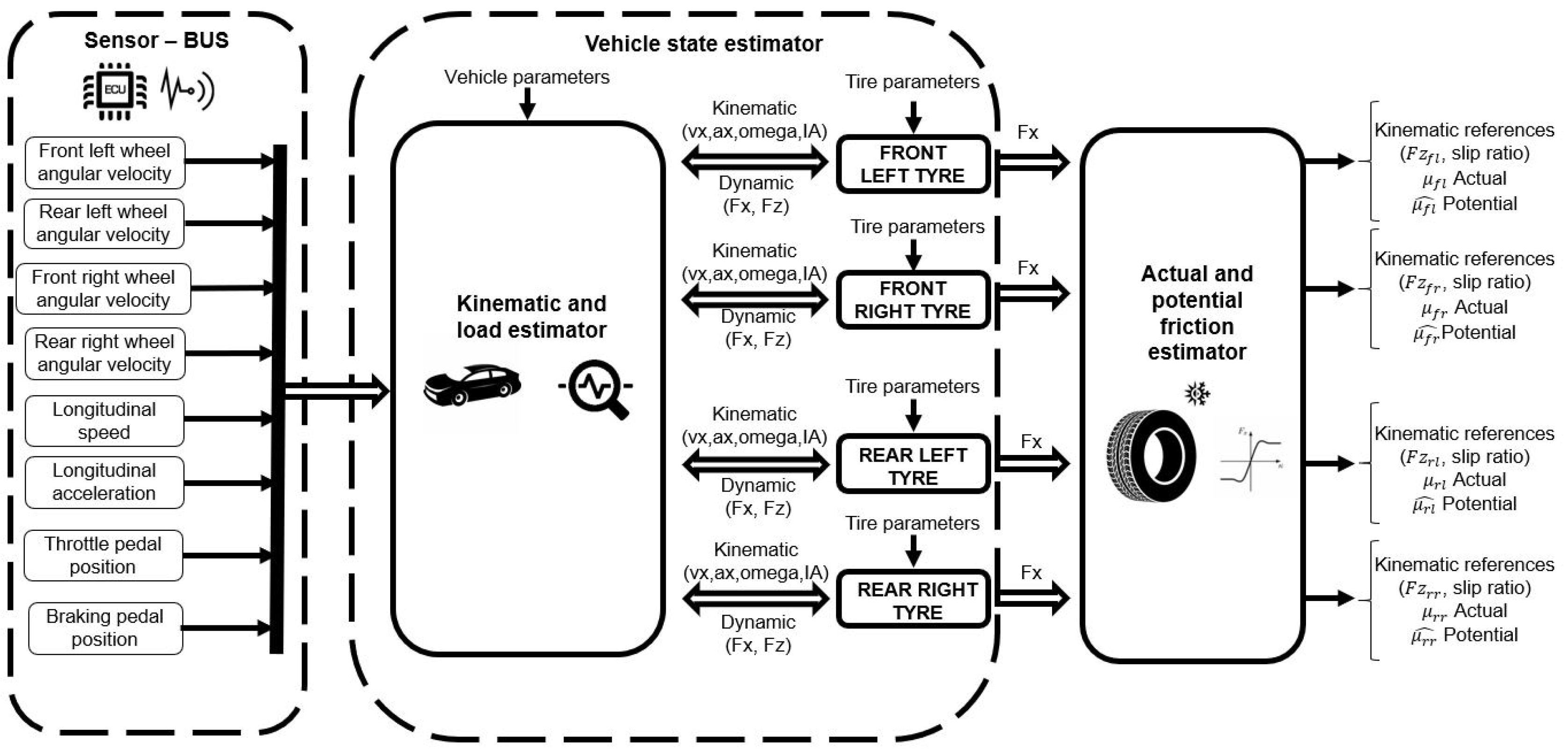
In Figure 5, the overall architecture of the developed model is shown. In particular, starting from the sensor-acquired input channels (on the left), the kinematic and load estimator calculate the vehicle state up to the kinematics on the wheel hubs. Then the tire model evaluates the state at the tire-road interface, and, using the above information, the actual and potential friction estimator module.

5. Design of the Road-Grip Aware Control Modules

The problem stated in Section 3 is here solved by designing road-grip aware driving functionalities for the four-wheel electric vehicle, leveraging the in-vehicle road grip estimate as in Equation (20). Specifically μ ^ has been chosen as μ ^ x i with i = 1 if only the front wheel drive is used, and as a weighted sum of μ ^ x i with with i = 1 , 2 , if both axles are used for actuation.

5.1. Predictive ACC Design

The ACC is responsible for longitudinal tracking in the autonomous vehicle-following process, so that the vehicle velocity is regulated to a desired speed, while maintaining a safety distance from the preceding vehicle, often named as leading vehicle in the technical literature. The controller is hierarchical and it is composed of a double feedback layer. Namely, the upper-control layer, acts as a reference governor generating the appropriate acceleration profile to be tracked, while also complying additional constraints related to driving comfort and energy consumption. The lower level is responsible for commanding the actuators and, hence, its robust design depends on the specific vehicle configuration.
Here, we focus on the design of the upper layer controller generating reference trajectories able to also improve driving safety leveraging the on-line prediction of road conditions. The predicted ACC is designed following the Model Predictive Control (MPC) approach allowing the continuous constrained optimization of the vehicle longitudinal dynamics. In contrast to the LQR, the MPC solves the problem over a finite time window, or prediction horizon, to make it tractable online. The optimization generates a sequence of control inputs to be imposed over the control horizon, but, according to the receding horizon principle, only the first element of the sequence is effectively applied to the plant. New inputs are received at the following time intervals and the procedure is iteratively repeated.
In order to design the controller, let us define a control oriented mode according the vehicle-following paradigm [55]:
d ˙ ( t ) = Δ v ( t ) ,
Δ ˙ v ( t ) = a l e a d ( t ) a ( t ) ,
where d ( t ) is the distance between the leading vehicle and the ego vehicle, while Δ v ( t ) = v v l e a d is their relative velocity (while a l e a d is the leading acceleration) and the velocity of the chassis of the ego vehicle v ( t ) undergoes the following longitudinal dynamics [55]:
v ˙ ( t ) = a ( t ) ,
a ˙ ( t ) = 1 τ ( a ( t ) + u ( t ) ) ,
where a ( t ) is the actual vehicle acceleration and τ the driveline time constant and u ( t ) the acceleration input.
Define now the distance error with respect to the desired space gap as e ( t ) = d ( t ) d d e s ( t ) , where the spacing policy d d e s ( t ) is computed as in Equation (3) with the head-way time being the following piece-wise function of the road grip:
τ H = τ ˜ H / 0.2 μ ^ 0.2 τ ˜ H / μ ^ 0.2 < μ ^ 1 τ ˜ H μ ^ > 1
where μ ^ is the estimated maximum available grip and τ ˜ H is the constant headway for an ideal dry road [28]. Note that Equation (25) ensures that the safety distance increases as the peak road friction decreases.
Let the state vector as x ( t ) = [ d ( t ) Δ v ( t ) v ( t ) a ( t ) ] T I R 4 , the output vector as y ( t ) = [ e ( t ) Δ v ( t ) v ( t ) a ( t ) ] T I R 4 and w ( t ) I R as the leader acceleration, i.e., w ( t ) = a l e a d ( t ) . The system in Equations (21) and (23) can be easily recast in the following state space representation
x ˙ ( t ) = A x ( t ) + B u ( t ) + W w ( t ) ,
y ( t ) = C x ( t ) Z ,
being
A = 0 1 0 0 0 0 0 1 0 0 0 1 0 0 0 1 τ , B = 0 0 0 1 τ , W = 0 1 0 0 , C = 1 τ H 0 0 0 1 0 0 0 0 1 0 0 0 0 1 , Z = d 0 0 0 0 .
However, in order to synthesize the MPC controller, Equation (26) are discretized with a fixed sample time T s leveraging the zero-order-hold method, thus yielding:
x ( k + 1 ) = A x ( k ) + B u ( k ) + W w ( k ) ,
y ( k ) = C x ( k ) Z ,
where, with an abuse of notation, the discrete-time system matrices have been labelled as the ones of the continuous-time model. Moreover, by augmenting the state vector as [ x ( k ) u ( k ) ] T , we can resort to the following off-set free formulation as:
x ( k + 1 ) = A B 0 1 x ( k ) + B 1 Δ u ( k ) + W 0 w ( k ) ,
y ( k ) = C 0 4 × 1 x ( k ) Z .
Note that the above formulation is really beneficial since the increment ( Δ u ( k ) / T s ) is the chassis jerk in discrete time, which is the crucial index for the driving comfort.
The ACC problem in Equation (1) is solved when system in Equation (31) is regulated to the origin while fulfilling at the same time additional tracking, comfort, consumption and safety constraints for all times k. In this perspective, the cost function embeds three different indexes, namely tracking capability, energy consumption and driving comfort. Tracking capability measures the performances in terms of distance and velocity errors, driving comfort is evaluated in terms of acceleration and jerk, finally the acceleration command is chosen as the performance index for energy consumption, yielding the following cost:
J 1 ( y ( k ) , Δ u ( k ) ) = q 1 | d ( k ) d d e s ( k , μ ^ ) | 2 + q 2 | Δ v ( k ) | 2 , + q 3 | a ( k ) | 2 + q 4 | u ( k ) | 2 + r | Δ u ( k ) | 2
which can be recasted in matrix form as:
J ( y ( k ) , Δ U ) = i = 0 H p 1 y k + i | k T Q y k + i | k + Δ u k + i T R Δ u k + i ,
where Q = diag { q 1 , q 2 , q 3 , q 4 } is a positive definite diagonal matrix, R I R + , H p and H c are the prediction and control horizon, respectively, Δ U = Δ [ Δ u k , , Δ u k + H c 1 ] is the control sequence during the horizon H c , while y k + i | k is the predicted output vector at time k + i , obtained by applying the input sequence starting from the state x ( k ) .
With respect to safety, road-grip constraints are introduced for the desired and actual acceleration, as:
u m i n ( μ ^ ) u ( k ) u m a x ( μ ^ ) ,
a m i n ( μ ^ ) a ( k ) a m a x ( μ ^ ) ,
with a m a x ( μ ^ ) = u m a x ( μ ^ ) = min ( 2 , μ ^ g ) , a m i n ( μ ^ ) = u m i n ( μ ^ ) = max ( 4 , μ ^ g ) , where μ ^ is the estimated maximum available grip and g the acceleration of gravity. The saturation values ( i.e., 2 and 4 ) are chosen as upper and lower limit, related to the ideal value for the grip set as 1 [28].
The constraints on the spacing and the maximum velocity are given as:
d m i n d ( k ) d m a x ,
v ( k ) v m a x ,
where d m i n is set to the standstill value d 0 (see Equation (3)) and v m a x is the maximum admissible speed depending on the legal requirements on the specific traveled road (urban, extra-urban, etc.). Note that this information can be acquired from a map-based on board service leveraging the GPS (Global Positioning System).
Finally, additional constraints on the control input are defined for further improving the driving comfort as:
Δ u m i n Δ u ( k ) Δ u m a x .
Given the above definitions, the constrained optimization problem to be on-line solved at each time step can be written as:
min Δ U J ( y ( k ) , Δ U )
subject to x ( k + 1 ) = A x ( k ) + B Δ u ( k ) + W w ( k )
y ( k ) = C x ( k ) Z
d m i n Δ d ( k ) d m a x
v ( k ) v m a x
a m i n a ( k ) a m a x
u m i n u ( k ) u m a x
Δ u m i n Δ u ( k ) Δ u m a x
Evaluating the output prediction as y k + i | k = C A i x k + j = 0 i 1 C A j B u k + i 1 j Z and substituting it into Equation (34), it is possible to obtain the cost J as a function of the only control sequence. Hence, after some algebraic manipulations, the cost in Equation (34) can be recasted in the following compact form:
J ( Δ U ) = Δ U T F Δ U + Λ Δ U ,
where F = R ¯ + D ¯ T Q ¯ D ¯ and Λ = 2 ( x ( k ) T C ¯ T + W T ( k ) E ¯ T Z ¯ T ) Q ¯ D ¯ , being R ¯ = diag { R , R , , R } I R H c , Q ¯ = diag { Q , Q , , Q } I R 5 H p × 5 H p ,
Z ¯ = [ Z T , Z T , , Z T ] T I R 4 H p × 1 , W ( k ) = [ w ( k ) w ( k ) w ( k ) ] T I R H p , C ¯ = [ ( C A ) T ( C A 2 ) T ( C A H p ) T ] T
D ¯ = C B 0 0 C A B C B 0 C A H p 1 B C A H p 2 B C A H p H c B ,
E ¯ = C W 0 0 C A W C W 0 C A H p 1 W C A H p 2 W C A H p H c W .
The constraints Equations (43)–(47) can be be also recast in a compact matrix form as:
H ¯ X S ¯ ,
Δ U U m a x ,
Δ U U m i n ,
where U m a x = Δ u m a x · 1 H c × 1 , U m i n = Δ u m i n · 1 H c × 1 , H ¯ = I H p × H p [ H H ] T , S ¯ = 1 H p × 1 S , being S = [ d m a x v m a x a m a x u m a x d m i n 0 a m i n u m i n ] T , and
H = 1 0 0 0 0 0 0 1 0 0 0 0 0 1 0 0 0 0 0 1 .
Hence, substituting the state prediction x k + i | k = A i x k + j = 0 i 1 A j B u k + i 1 j in Equation (51), we obtain:
H ¯ B ¯ Δ U S ¯ H ¯ A ¯ x k H ¯ E ¯ W ( k ) ,
Δ U U m a x ,
Δ U U m i n .
From Equations (48)–(55) we finally formulate the linearly constrained quadratic optimization problem in a compact form as:
min Δ U J ( Δ U )
subject to G Δ U Γ
where G = [ ( H ¯ B ¯ ) T I H c I H c ] T and Γ = [ ( S ¯ H ¯ A ¯ x k H ¯ E ¯ W ( k ) ) T U m a x T U m i n T ] T .
One last consideration must be made about the feasibility of problem Equation (58). Indeed, due to the fact that d d e s depends on the estimated grip ratio, at some point in time the constraint in Equation (43) could be violated, thus leading to the unfeasibility of the problem. This violation can actually be tolerated for small periods of time, so the it is treated in practice as a soft constraint [56], i.e., it is added to the cost function with a slack variable. When the constraint is not violated the slack variable is null and the original problem is obtained.

5.2. Autonomous Emergency Brake

Road accidents and fatalities statistics are reported annually, showing the relation between accidents and drivers behaviour [3,4]. Moreover, the authors in [57] showed that the collision risk increases with the degradation of road conditions. The Autonomous Emergency Brake is one of the most effective driving functionalities for collision prevention and social cost lowering linked to accidents. Nonetheless, EuroNCAP tests are being carried on roads with friction peaks of at least 0.9, even if in real situations a lower value reduces the safeness and the robustness of the whole system.
In this perspective, the aim of the grip-aware AEB system proposed by the authors is to identify the collision risk depending on the actual road conditions and, hence, to take control of the brakes to avoid possible accidents or at least to reduce their severity. Here, we base the decision-making of AEB according to the Time-To-Collision (TTC) in Equation (4), where the detection threshold depends on the estimated road-grip as:
T T C t h ( t , μ ^ ) = v ( t ) μ ^ a b r k ,
where a b r k is the deceleration value commanded to the ABS in case of emergency, i.e., 9.8 m/s 2 .

5.3. Anti-Lock Braking System

Once an emergency braking is commanded from the AEB, the ABS has to drive the brake system preventing wheels from locking during the hard braking maneuver. Here we propose a Sliding Mode (SMC) ABS controller that leverages the on-line estimation of the road-grip in order to provide a safe braking automatic maneuver for a vehicle-following process also in the presence of hard rainy or icy pavement. This choice is due to SMC’s enhanced stability performances with respect to classical control architectures [58] (e.g., proportional action). In particular it can be shown that matched disturbances (uncertainties entering the system through the same channel as the control) are rejected, at least below the actuation limits, moreover due to the controller nonlinear nature, larger stability margins can be achieved.
First, let us define a control-oriented model, i.e., the quarter car model, in which we neglect the lateral and yaw motion of the wheel, thus obtaining a model dealing with the wheel rotational dynamics and longitudinal vehicle dynamics. The rotational dynamics of the wheel is described by
I w Ω ˙ = T b R r F x ,
where I w is the moment of inertia about the wheel axis of rotation, Ω is the angular velocity, T b is the braking torque, R r is the wheel rolling radius and F l is the force produced by the friction reaction. The longitudinal vehicle dynamics are simply modeled as
m v ˙ = F x .
where m is the vehicle mass.
The control goal is to yield λ to a reference value λ * during braking [59]. To this aim we define the following sliding surface
σ ( t ) = λ ( t ) λ 🟉 ,
where λ 🟉 is the optimal slip obtained from the friction estimator (see Section 4) and λ is the longitudinal slip with dynamics as:
λ ˙ = 1 v ( 1 λ m + R r 2 I w ) F x + R r v I w T b .
Due to the inertia differences between wheel and vehicle, we can consider the velocity v as slowly varying, thus reducing Equation (64) to a single-input single-output system, where the control law can be defined as:
u ( t ) = T b = u c ( t ) + u s w ( t ) ,
where u c is the continuous term, or equivalent control [58], and u s w the discontinuous term. The equivalent control input is is responsible for keeping the trajectories on σ , i.e.,
σ ˙ = 0 u c = ( ( 1 λ ) I w m R r + R r ) F z μ x i , a c t u a l ,
where the force F x = F z μ x i , a c t u a l , where F z is the tire vertical load, and μ x i , a c t u a l the instantaneous friction value provided by the estimation module; note that the subscript i = [ 1 , 2 ] identifies front and rear tire depending from the axle involved (see Equation (17)).
Closed-loop stability can be easily proven by considering the following Lyapunov function V ( λ ) = 1 2 σ 2 and its derivative V ˙ ( λ ) = σ σ ˙ . Substituting Equations (65) and (66) into the expression of V ˙ , we obtain
V ˙ ( λ ) = σ σ ˙ = σ ( R r v I w u s w ) .
Hence, selecting u s w = v I w R r η s g n ( σ ) it follows that
V ˙ ( λ ) = η σ s g n ( σ ) = η | σ | < 0 ,
where η > 0 . In so doing, the surface σ is attractive and the closed-loop is asymptotically stable.
Note that, in order to avoid the well-known chattering problem of sliding mode controllers, for its practical implementation the sign function in Equation (68) has been substituted by the hyperbolic tangent function. Furthermore, since controllability is lost when the vehicle speed is approaching zero (see Equation (64)), following a common practice for implementing the ABS, the controller is disabled at the very low velocities.

6. Co-Simulation Platform

The design for improved solutions of safety related features has been significantly eased thank to the usage of appropriate simulation platforms, enabling engineers to design, test and validate the control architectures through models in a singular platform, and therefore reducing the development cost and the time to market.
Here, we propose a co-simulation platform for Model-In-the-Loop (MIL), where autonomous vehicle has been tested in a realistic traffic scenario. This co-simulation environment, represented in Figure 6, has been built leveraging the following four main components:
  • MATLAB/Simulink platform, a widely used framework to model dynamical systems and to design control architectures. Indeed, through an easy to use of its graphical interface, it is possible to develop controllers according to the well-known Model-based Control Design approach. The vehicle dynamics model, implemented in the MATLAB/Simulink environment and employed for the evaluation of the control logic performance in vehicle-following maneuvers, is an efficient 15 degrees of freedom lumped-parameter full vehicle model (LPFVM), described in [60] with a MF-based tire model [54]. The LPFVM is based on a set of Ordinary Differential Equations (ODEs) governing the dynamic equilibrium of the vehicle chassis, including three translational and three rotational equilibrium conditions, and of each wheel, comprising a translational equilibrium along the vertical direction and a rotational equilibrium around the spindle axis. Furthermore, the braking actuation is achieved through a standard hydraulic system made of a master cylinder, a reservoir, a pump and two valves for each wheels which are used to build braking pressure. Details on its model, and the related parameters, can be found in [61] and references therein.
  • SUMO (Simulation of Urban MObility), an open-source road traffic simulation package, enabling the user to model entities such as vehicles, traffic lights, road networks, vehicle routing. Each entity is simulated microscopically, meaning that it is possible to control each of them singularly, while the whole scenario is emulated by its internal engine built upon realistic driving models.
  • Friction estimator module, allowing the on-board estimation of the current tire-road interaction state and the potential friction value.
In particular, the Simulink environment has been adopted to describe a highly detailed dynamical behavior of the autonomous vehicle under control, while SUMO emulates the traffic scenario and the road network, where the actual road grip in different scenario can change to mimic the effect of different environmental conditions to be studied.
The interaction between the different modules for the co-simulation is allowed by Traci, an integration tool provided by SUMO. The library TraCI4Matlab has been employed to couple the vehicle, the road and the SUMO environment model in Simulink.

7. Performance Analysis

The co-simulation platform described in Section 6 has been exploited to assess the effectiveness of the proposed grip-aware functionalities.
The illustrative results, reported in the following, refer to a vehicle-following process along a typical motorway where the ego vehicle moves with an initial velocity of v ( 0 ) = 30 m/s, having an initial space gap d ( 0 ) = 90 m from its predecessor (leader) that moves with an initial speed of v l e a d ( 0 ) = 20 m/s. The leader is a human-driven vehicle emulated through SUMO, whose realistic velocity profile accounts for both speed limits and driver imperfection parameters (details on how to model the human-drivers via SUMO can be found in [62] and references therein). Further characteristics parameters of the road scenario, as well as the ones for the controller, are summarized in Table 1.
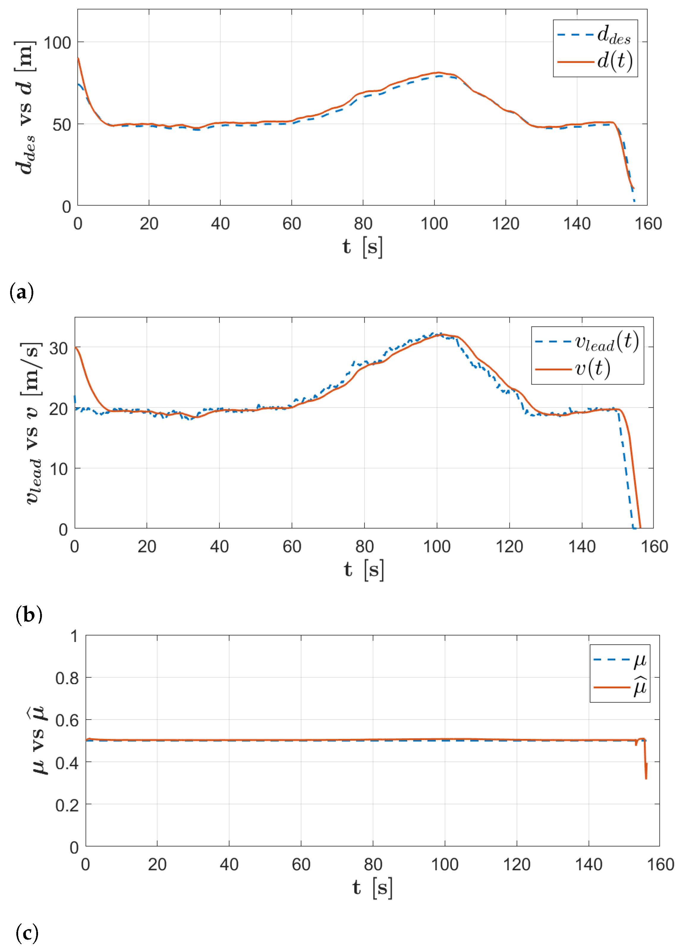
The first exemplar driving scenario refers to vehicles moving in the presence of heavy rain, with actual road grip μ = 0.5 . Due to the presence of an obstacle, at the time instant t = 150 s the leading vehicle performs a sudden hard-brake inducing the maximum deceleration allowed by the road grip, i.e., μ g . Results in Figure 7 show how leveraging the on line estimation of the actual road condition (reported in Figure 7c), the ego vehicle is able to safely perform the velocity tracking while always preserving the desired safe space gap about d d e s ( t , μ ^ ) , depending on the grip estimate.
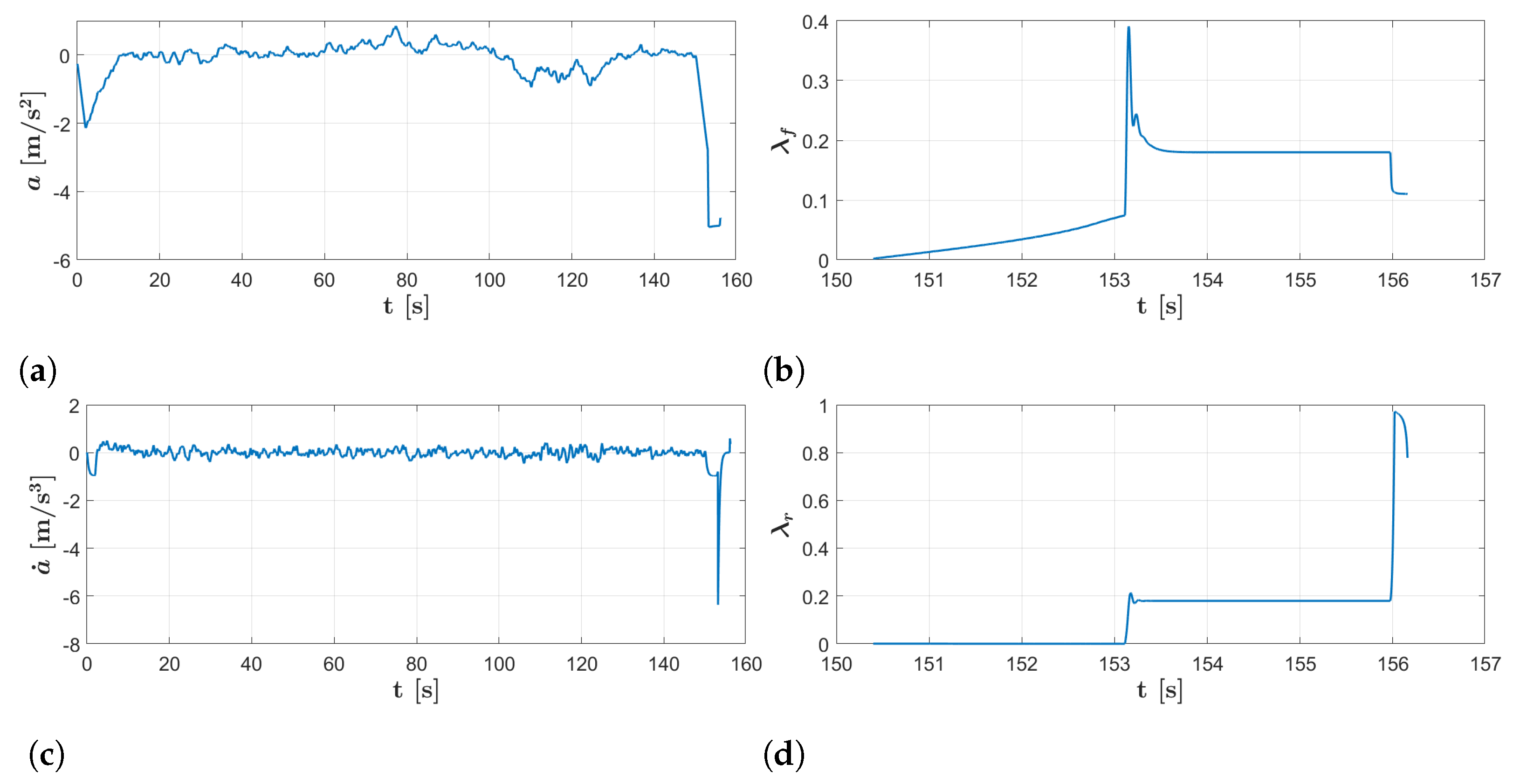
In addition, it is worth to note that the emergency brake is safely performed and vehicles correctly reach the required standstill distance when they finally stops without colliding. According to the theoretical derivation, the Predictive ACC also guarantees both acceleration and jerk of the ego vehicle fulfill the comfort constraints until the leading vehicle performs the hard brake at time instant t = 150 s (see Figure 8). Indeed, from this time instant the ACC tries to handle this hazardous braking maneuver, but the necessity of hard deceleration leads to the activation of the AEB, which hence commands the maximum braking torque to be imposed, obviously ignoring the comfort constraints which have less priority w.r.t. the safety.
In so doing, the collision is safely avoided (see Figure 7), but higher acceleration and jerk can be appreciated during the braking until the stop, as shown in Figure 8. It is also worth to note that, when the emergency braking maneuver is commanded from AEB, than the ABS is responsible ensuring that the longitudinal slips of the tires are regulated to the optimal reference value λ * returned by the friction estimator module as described in Section 4 (see Figure 8b–d).
In order to clearly appreciate the enhancement of the here proposed grip-aware driving functionalities with respect to classical ACC, AEB and ABS strategies, the above maneuver has been repeated without leveraging the knowledge of the actual road-grip.
Results in Figure 9 disclose that in this case the ACC is still capable of tracking the velocity references, while ensuring a desired gap that obviously depends only from the actual vehicle velocity, namely d d e s ( t ) = d 0 + τ ˜ H v ( t ) . However, when the leading vehicle performs the emergency hard brake, the safety distance results to be too small, the AEB is activated too late and it is impossible to avoid the collision that, hence, occurs at the time instant t = 154 s with a velocity of v 10 m/s = 36 km/h.
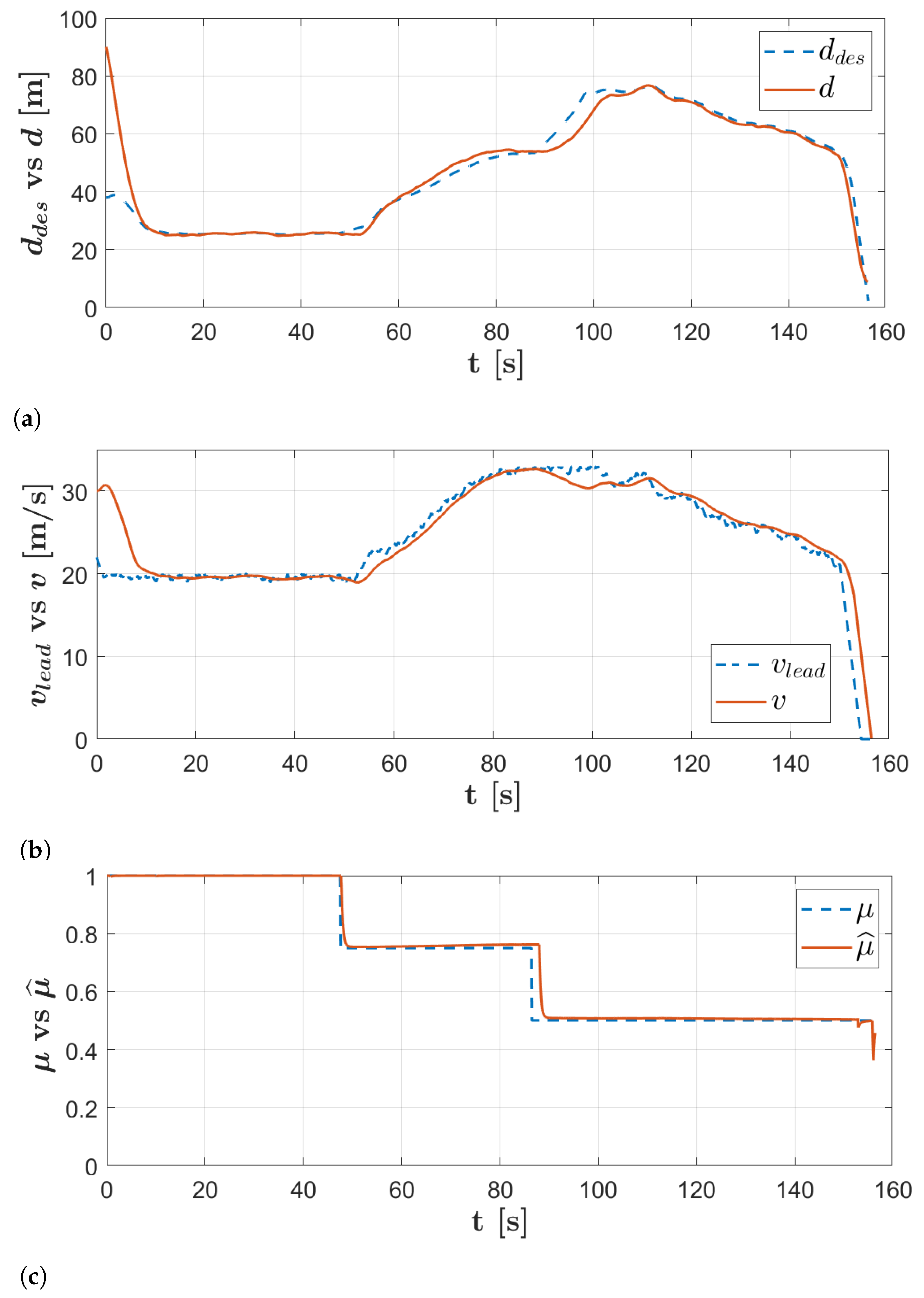
A further investigation of the achievable performance has been performed in the case when vehicles are moving in variable environmental conditions, i.e., the actual grip changes in time due to different climatic condition that have to be faced during travelling. Specifically, vehicle drives from dry asphalt to wet road, i.e., the actual maximum road grip starts from μ = 1 and than decreases, into two steps, until μ = 0.5 (see Figure 10c). The initial dynamic condition of the vehicles match the ones chosen in the previous driving scenario.
Results depicted in Figure 10 show how the on-line road-grip estimate is performed with good precision (always below 1 % at steady state). Furthermore, as the road grip decreases the safe distance is correctly adapted in order to provide a safer spacing with respect to the current adhesion (see Figure 10a) and the predictive ACC correctly tracks the reference values without any constraints violation. As in the previous driving scenario, at the time instant a t = 150 s an emergency situation emerges inducing the hard braking maneuver. Also in this case the combination of the grip-aware AEB and ABS is able of ensuring a safe stopping without collision.
Final exemplar results refer to a typical Stop & Go scenario where continuous smooth accelerations and decelerations occur due to traffic congestion. In order to better assess the collision risk and the safety margins during traffic jam, we leverage the following well-known non-dimensional collision-index γ ( t ) [34]:
γ ( t ) = d ( t ) d b r d w d b r ,
where d ( t ) is the actual distance between the vehicles, d b r is the breaking critical distance and d w is the warning critical distance. Note that the above index witnesses the possibility of an incoming crash due to the current driving situation. Specifically, when it is positive and greater than the unity a safe situation is detected, while, if it is below the unity, a possible dangerous scenario is signalized.
Results depicted in Figure 11 clearly confirm that, leveraging the road-aware driving control architecture, the safety index γ ( t ) never goes below the unity, while, on the other hand, if the estimate of the road-grip is not exploited for the automated driving functionalities the collision index alerts for possible dangerous situations during the deceleration phases (see Figure 11), reducing the vehicle safety.
The effectiveness of the approach w.r.t. safety is finally summarized in Table 2. Here, results clearly disclose that, adapting in real-time the driving policy to the current road-grip, the overall automated driving performance can be enhanced with the minimal values assumed by the safety indexes [34] (i.e., time-to-collision, relative distance w.r.t. the predecessor and collision index γ as in Equation (69)) comparable with the ones required in the case of ideal road conditions.

8. Conclusions

This paper is focused on the development of a new control architecture for vehicles, based on the estimation of the maximum achievable road friction coefficient.
The proposed technique for real-time road friction estimation in different environmental conditions is based on both bicycle model to evaluate the state of the vehicle and a tire Magic Formula model based on a slip-slope approach. The introduction of the grip value in ADAS application, in particular for the longitudinal dynamics of the vehicle chassis, composed of Adaptive Cruise Control (ACC) and Autonomous Emergency Brake (AEB), and the Antilock Braking System (ABS), allows the vehicle to work at the maximum performance in all operating conditions.
In this study, the technique has been performed on a simulation platform, consisting of different components working simultaneously. A vehicle dynamics model, implemented in the MAT-LAB/Simulink environment, has been employed for the evaluation of the control logic performance in vehicle-following maneuvers. In addition, a SUMO environment has been implemented to realize different traffic scenarios and environmental conditions. Finally, the Friction algorithm has been used to perform the estimation of the road coefficient.
The simulation has been carried out in different environmental and vehicle kinematic conditions. According to the results, the control system has been improved by the involvement of the current and potential friction coefficient evaluated in run-time. The improvement basically results from the development of a control system that is able to avoid collisions in any environmental condition. The potential grip has been therefore demonstrated to be crucial for the autonomous driving systems.
Future developments will also comprehend the lateral dynamics. Several authors have already tackled the problem describing different techniques and modelling approaches [63,64,65]. The authors plan also to include the impact of the road bank angle and slope, the tire combined interaction characteristics, as well as, the variations of the vehicle dynamic behaviour due to the tire intrinsic multi-physics (i.e., wear and temperature effects) [66,67].

Author Contributions

Conceptualization and supervision, S.S. and A.S.; methodology, S.S., V.M.A. and A.S.; software and investigation, N.A. and V.M.A.; formal analysis, S.S.; resources and visualization, R.B.; data curation, N.A. All authors have read and agreed to the published version of the manuscript.

Funding

This research received no external funding.

Institutional Review Board Statement

Not applicable.

Informed Consent Statement

Informed consent was obtained from all subjects involved in the study.

Data Availability Statement

No new data were created or analyzed in this study. Data sharing is not applicable to this article.

Conflicts of Interest

The authors declare no conflict of interest.

Abbreviations

The following abbreviations are used in this manuscript:
A D A S Advanced Driver Assistance System
M P C Model Predictive Control
A C C Adaprive Cruise Control
A E B Autonomous Emergency Braking
L Q R Linear Quadratic Regulator
T T C Time To Collision
P I D Proportional-Integral-Derivative
S A E Society of Automotive Engineers
A B S Anti-lock Braking System
T R I C K Tire Road Interaction Characterization and Knowledge
M F Magic Formula
E C U s Electronic Control Units
C A N Controller Area Network
G P S Global Positioning System
S M C Sliding Mode Control
M I L Model In the Loop
S U M O Simulation of Urban MObility
L P F V M Lumped-Parameter Full Vehicle Model
F E M Finite element Methods
c . o . g . Center of Gravity
vlongitudinal velocity evaluated at the c.o.g.
alongitudinal acceleration
Ω wheel speed
I A inclination angle
v x C P longitudinal velocity evaluated at the contact point
v x s p i n d l e spindle velocity
mvehicle mass
gacceleration of gravity
l f distance c.o.g. - front axle
l r distance c.o.g. - rear axle
Lwheelbase
ρ air density
hheight c.o.g.
C x longitudinal drag coefficient
C z lift coefficient
I ω moment of inertia about the wheel axis of rotation
I z wheel moment of inertia
R r rolling radius
A v master section
W f static load - front axle
W r static load - rear axle
Δ F z load transfer
F z a e r o i aerodynamic down force
F i , i n e r t i a inertial force
F x i longitudinal force
F x i , r e f R o a d longitudinal force evaluated on a reference road surface
F z i normal force
μ x i , a c t u a l actual friction coefficient estimated
μ x i , r e f R o a d actual friction coefficient estimated on a reference road surface
μ ^ x i potential friction coefficient estimated
λ slip ratio
edistance error to the desired d d e s
T b braking torque
ddistance lead to ego vehicle
d d e s ACC desired distance
d 0 minimum spacing
τ H headway time
a l e a d leading vehicle acceleration
v l e a d leading vehicle velocity
τ driveline time constant
ucontrol input
JACC cost function
QACC output weight
rACC incremental control effort weight
H c ACC control horizon
H p ACC prediction horizon
T s ACC sampling time
a b r k AEB deceleration command
σ sliding surface
η switching control gain
d ω warning critical distance
d b r braking critical distance
γ safety index

References

  1. Urmson, C.; Anhalt, J.; Bagnell, D.; Baker, C.; Bittner, R.; Clark, M.; Dolan, J.; Duggins, D.; Galatali, T.; Geyer, C.; et al. Autonomous driving in urban environments: Boss and the urban challenge. J. Field Robot. 2008, 25, 425–466. [Google Scholar] [CrossRef] [Green Version]
  2. INRIX. Congestion Costs Each American 97 h, $ 1,348 A Year. Available online: https://inrix.com/press-releases/scorecard-2018-us/#:~:text=Americans%20lost%20an%20average%20of,the%20top%2060%20urban%20areas (accessed on 7 June 2018).
  3. USDOT. Early Estimate of Motor Vehicle Traffic Fatalities for the First 9 Months of 2019. Available online: https://crashstats.nhtsa.dot.gov/Api/Public/ViewPublication/812874#:~:text=A%20statistical%20projection%20of%20traffic,as%20shown%20in%20Table%201. (accessed on 3 September 2019).
  4. WHO. Global Status Report on Road Safety; WHO: Geneva, Switzerland, 2018. [Google Scholar]
  5. Matthaios, V.N.; Kramer, L.J.; Crilley, L.R.; Sommariva, R.; Pope, F.D.; Bloss, W.J. Quantification of within-vehicle exposure to NOx and particles: Variation with outside air quality, route choice and ventilation options. Atmos. Environ. 2020, 240, 117810. [Google Scholar] [CrossRef]
  6. Wallington, T.J.; Sullivan, J.L.; Hurley, M.D. Emissions of CO2, CO, NOx, HC, PM, HFC-134a, N2O and CH4 from the global light duty vehicle fleet. Meteorol. Z. 2008, 17, 109–116. [Google Scholar] [CrossRef]
  7. Walta, L.; Marchau, V.; Brookhuis, K. Stakeholder preferences of advanced driver assistance systems (ADAS)—A literature review. In Proceedings of the 13th World Congress and Exhibition on Intelligent Transport Systems and Service, London, UK, 8–12 October 2006. [Google Scholar]
  8. Tsourveloudis, N.C.; Valavanis, K.P.; Hebert, T. Autonomous vehicle navigation utilizing electrostatic potential fields and fuzzy logic. IEEE Transact. Robot. Automat. 2001, 17, 490–497. [Google Scholar] [CrossRef]
  9. Levinson, J.; Askeland, J.; Becker, J.; Dolson, J.; Held, D.; Kammel, S.; Kolter, J.Z.; Langer, D.; Pink, O.; Pratt, V.; et al. Towards fully autonomous driving: Systems and algorithms. In Proceedings of the 2011 IEEE Intelligent Vehicles Symposium (IV), Baden-Baden, Germany, 5–9 June 2011; pp. 163–168. [Google Scholar]
  10. Minguez, J.; Lamiraux, F.; Laumond, J.P. Motion planning and obstacle avoidance. In Springer Handbook of Robotics; Springer: Berlin, Germany, 2016; pp. 1177–1202. [Google Scholar]
  11. Paden, B.; Čáp, M.; Yong, S.Z.; Yershov, D.; Frazzoli, E. A survey of motion planning and control techniques for self-driving urban vehicles. IEEE Transact. Intell. Veh. 2016, 1, 33–55. [Google Scholar] [CrossRef] [Green Version]
  12. Antonov, S.; Fehn, A.; Kugi, A. Unscented Kalman filter for vehicle state estimation. Veh. Syst. Dynam. 2011, 49, 1497–1520. [Google Scholar] [CrossRef]
  13. Wenzel, T.A.; Burnham, K.; Blundell, M.; Williams, R. Dual extended Kalman filter for vehicle state and parameter estimation. Veh. Syst. Dynam. 2006, 44, 153–171. [Google Scholar] [CrossRef]
  14. Liu, W.; He, H.; Sun, F. Vehicle state estimation based on minimum model error criterion combining with extended Kalman filter. J. Franklin Inst. 2016, 353, 834–856. [Google Scholar] [CrossRef]
  15. Collado, J.M.; Hilario, C.; De la Escalera, A.; Armingol, J.M. Model based vehicle detection for intelligent vehicles. In Proceedings of the IEEE Intelligent Vehicles Symposium, Parma, Italy, 14–17 June 2004; pp. 572–577. [Google Scholar]
  16. Hojjati-Emami, K.; Dhillon, B.; Jenab, K. Reliability prediction for the vehicles equipped with advanced driver assistance systems (ADAS) and passive safety systems (PSS). Int. J. Ind. Eng. Comput. 2012, 3, 731–742. [Google Scholar] [CrossRef]
  17. Cafiso, S.; Di Graziano, A. Evaluation of the effectiveness of ADAS in reducing multi-vehicle collisions. Int. J. Heavy Veh. Syst. 2012, 19, 188–206. [Google Scholar] [CrossRef]
  18. Park, S.J.; Kim, T.Y.; Kang, S.M.; Koo, K.H. A novel signal processing technique for vehicle detection radar. In Proceedings of the IEEE MTT-S International Microwave Symposium Digest, Philadelphia, PA, USA, 8–13 June 2003; Volume 1, pp. 607–610. [Google Scholar]
  19. Varghese, J.Z.; Boone, R.G. Overview of autonomous vehicle sensors and systems. In Proceedings of the International Conference on Operations Excellence and Service Engineering, Orlnado, FL, USA, 10–11 September 2015; pp. 178–191. [Google Scholar]
  20. Dickson, M.A.; Noguchi, N.; Zhang, Q.; Reid, J.F.; Will, J.D. Sensor-Fusion Navigator for Automated Guidance of Off-Road Vehicles. U.S. Patent 6,445,983, 3 September 2002. [Google Scholar]
  21. Kocić, J.; Jovičić, N.; Drndarević, V. Sensors and sensor fusion in autonomous vehicles. In Proceedings of the 2018 26th Telecommunications Forum (TELFOR), Belgrade, Serbia, 20–21 November 2018; pp. 420–425. [Google Scholar]
  22. Ndoye, M.; Totten, V.F.; Krogmeier, J.V.; Bullock, D.M. Sensing and signal processing for vehicle reidentification and travel time estimation. IEEE Transact. Intell. Transport. Syst. 2010, 12, 119–131. [Google Scholar] [CrossRef]
  23. Farroni, F. T.R.I.C.K.-Tire/Road Interaction Characterization & Knowledge—A tool for the evaluation of tire and vehicle performances in outdoor test sessions. Mech. Syst. Signal Proces. 2016, 72, 808–831. [Google Scholar] [CrossRef]
  24. Weißmann, A.; Görges, D.; Lin, X. Energy-optimal adaptive cruise control combining model predictive control and dynamic programming. Control Eng. Pract. 2018, 72, 125–137. [Google Scholar] [CrossRef]
  25. Weißmann, A.; Görges, D.; Lin, X. Energy-optimal adaptive cruise control based on model predictive control. IFAC-Papers OnLine 2017, 50, 12563–12568. [Google Scholar] [CrossRef]
  26. Sun, C.; Chu, L.; Guo, J.; Shi, D.; Li, T.; Jiang, Y. Research on adaptive cruise control strategy of pure electric vehicle with braking energy recovery. Adv. Mech. Eng. 2017, 9, 1687814017734994. [Google Scholar] [CrossRef]
  27. Zhang, S.; Luo, Y.; Li, K.; Li, V. Real-Time Energy-Efficient Control for Fully Electric Vehicles Based on an Explicit Model Predictive Control Method. IEEE Transact. Veh. Technol. 2018, 67, 4693–4701. [Google Scholar] [CrossRef]
  28. Zhang, S.; Zhuan, X. Model-Predictive Optimization for Pure Electric Vehicle during a Vehicle-Following Process. Math. Probl. Eng. 2019, 2019, 5219867. [Google Scholar] [CrossRef]
  29. Lee, D.; Kim, S.; Kim, C.; Huh, K. Development of an autonomous braking system using the predicted stopping distance. Int. J. Automot. Technol. 2014, 15, 341–346. [Google Scholar] [CrossRef]
  30. Xiong, H.; Ling, Z.; Yue, R.; Yinong, L.; Zhenfei, Z.; Yusheng, L.; Qiang, Z.; Zhoubing, X. Research on control strategy of automatic emergency brake system based on Prescan. In Proceedings of the IET International Conference on Intelligent and Connected Vehicles (ICV 2016), Chongqing, China, 22–23 September 2016; pp. 1–6. [Google Scholar]
  31. Naseralavi, S.; Nadimi, N.; Saffarzadeh, M.; Mamdoohi, A.R. A general formulation for time-to-collision safety indicator. Proc. ICE Transp. 2013, 166, 294–304. [Google Scholar] [CrossRef]
  32. Abdul Hamid, U.Z.; Ahmad Zakuan, F.R.; Zulkepli, K.; Azmi, M.Z.; Zamzuri, H.; Abdul Rahman, M.A.; Zakaria, M. Autonomous emergency braking system with potential field risk assessment for frontal collision mitigation. In Proceedings of the 2017 IEEE Conference on Systems, Process and Control (ICSPC), Malacca, Malaysia, 15–17 December 2017; pp. 71–76. [Google Scholar]
  33. Lee, I.H.; Luan, B.C. Design of Autonomous Emergency Braking System Based on Impedance Control for 3-Car Driving Scenario; SAE Technical Paper; SAE International: Warrendale, PE, USA, 2016. [Google Scholar] [CrossRef]
  34. Moon, S.; Moon, I.; Yi, K. Design, tuning, and evaluation of a full-range adaptive cruise control system with collision avoidance. Control Eng. Pract. 2009, 17, 442–455. [Google Scholar] [CrossRef]
  35. Mullakkal, B.; Wang, M.; Arem, B.; Happee, R. Design and Analysis of Full Range Adaptive Cruise Control with Integrated Collision Avoidance Strategy. In Proceedings of the 2016 IEEE 19th International Conference on Intelligent Transportation Systems (ITSC), Rio de Janeiro, Brazil, 1–4 November 2016. [Google Scholar] [CrossRef] [Green Version]
  36. Shakouri, P.; Ordys, A.; Askari, M. Adaptive cruise control with stop&go function using the state-dependent nonlinear model predictive control approach. ISA Transact. 2012, 51, 622–631. [Google Scholar] [CrossRef]
  37. Zhao, D.; Hu, Z.; Xia, Z.; Alippi, C.; Zhu, Y.; Wang, D. Full-range adaptive cruise control based on supervised adaptive dynamic programming. Neurocomputing 2014, 125, 57–67. [Google Scholar] [CrossRef]
  38. Khaleghian, S.; Emami, A.; Taheri, S. A technical survey on tire-road friction estimation. Friction 2017, 5, 123–146. [Google Scholar] [CrossRef] [Green Version]
  39. Leng, B.; Jin, D.; Xiong, L.; Yang, X.; Yu, Z. Estimation of tire-road peak adhesion coefficient for intelligent electric vehicles based on camera and tire dynamics information fusion. Mech. Syst. Signal Proces. 2021, 150, 107275. [Google Scholar] [CrossRef]
  40. Berntorp, K.; Quirynen, R.; Di Cairano, S. Friction Adaptive Vehicle Control. U.S. Patent App. 16/299,285, 17 September 2020. [Google Scholar]
  41. Hu, J.; Rakheja, S.; Zhang, Y. Tire-Road Friction Coefficient Estimation under Constant Vehicle Speed Control. IFAC-Papers OnLine 2019, 52, 136–141. [Google Scholar] [CrossRef]
  42. Chen, Y.; Wang, J. Adaptive vehicle speed control with input injections for longitudinal motion independent road frictional condition estimation. IEEE Transact. Vech. Technol. 2011, 60, 839–848. [Google Scholar] [CrossRef]
  43. Rajamani, R.; Piyabongkarn, N.; Lew, J.; Yi, K.; Phanomchoeng, G. Tire-road friction-coefficient estimation. IEEE Control Syst. Mag. 2010, 30, 54–69. [Google Scholar]
  44. Ilas, C. Electronic sensing technologies for autonomous ground vehicles: A review. In Proceedings of the 2013 8th International Symposium on Advanced Topics in Electrical Engineering (ATEE), Bucharest, Romania, 23–25 May 2013; pp. 1–6. [Google Scholar]
  45. Winsum, W.V.; Heino, A. Choice of time-headway in car-following and the role of time-to-collision information in braking. Ergonomics 1996, 39, 579–592. [Google Scholar] [CrossRef]
  46. Hayward, J.C. Near Miss Determination through Use of a Scale of Danger; Sponsored by Committee on Effectiveness of Operational Measures: Basel, Switzerland, 1972. [Google Scholar]
  47. Zhenhai, G.; Jun, W.; Hongyu, H.; Wei, Y.; Dazhi, W.; Lin, W. Multi-argument control mode switching strategy for adaptive cruise control system. Procedia Eng. 2016, 137, 581–589. [Google Scholar] [CrossRef] [Green Version]
  48. De Martino, M.; Farroni, F.; Pasquino, N.; Sakhnevych, A.; Timpone, F. Real-time estimation of the vehicle sideslip angle through regression based on principal component analysis and neural networks. In Proceedings of the 2017 IEEE International Systems Engineering Symposium (ISSE), Vienna, Austria, 11–13 October 2017; pp. 1–6. [Google Scholar]
  49. Guiggiani, M. The Science of Vehicle Dynamics: Handling, Braking, and Ride of Road and Race Cars; Springer Science & Business Media: Berlin, Germany, 2014. [Google Scholar]
  50. Dell’Annunziata, G.N.; Lenzo, B.; Farroni, F.; Sakhnevych, A.; Timpone, F. A New Approach for Estimating Tire-Road Longitudinal Forces for a Race Car. In IFToMM World Congress on Mechanism and Machine Science; Springer: Berlin, Germany, 2019; pp. 3601–3610. [Google Scholar]
  51. Romano, L.; Sakhnevych, A.; Strano, S.; Timpone, F. A hybrid tyre model for in-plane dynamics. Vehic. Syst. Dynam. 2020, 58, 1123–1145. [Google Scholar] [CrossRef]
  52. Gipser, M. Ftire: A physically based application-oriented tyre model for use with detailed mbs and finite-element suspension models. Vehic. Syst. Dynam. 2005, 43, 76–91. [Google Scholar] [CrossRef]
  53. Gallrein, A.; Bäcker, M. Cdtire: A tire model for comfort and durability applications. Vehic. Syst. Dynam. 2007, 45, 69–77. [Google Scholar] [CrossRef]
  54. Pacejka, H. Tire and Vehicle Dynamics; Elsevier: Amsterdam, The Netherlands, 2005. [Google Scholar]
  55. Rajamani, R. Vehicle Dynamics and Control; Springer Science & Business Media: New York, NY, USA, 2011. [Google Scholar]
  56. Eben Li, S.; Li, K.; Wang, J. Economy-oriented vehicle adaptive cruise control with coordinating multiple objectives function. Vehic. Syst. Dynam. 2013, 51, 1–17. [Google Scholar] [CrossRef]
  57. Edwards, J.B. The Relationship Between Road Accident Severity and Recorded Weather. J. Safety Res. 1998, 29, 249–262. [Google Scholar] [CrossRef]
  58. Utkin, V.; Guldner, J.; Shijun, M. Sliding Mode Control in Electro-Mechanical Systems; CRC Press: Boca Raton, FL, USA, 1999; Volume 34. [Google Scholar]
  59. Pasillas-Lépine, W.; Loría, A.; Gerard, M. Design and experimental validation of a nonlinear wheel slip control algorithm. Automatica 2012, 48, 1852–1859. [Google Scholar] [CrossRef]
  60. Perrelli, M.; Farroni, F.; Timpone, F.; Mundo, D. Analysis of Tire Temperature Influence on Vehicle Dynamic Behaviour Using a 15 DOF Lumped-Parameter Full-Car Model. In International Conference on Robotics in Alpe-Adria Danube Region; Springer: Berlin, Germany, 2020; pp. 266–274. [Google Scholar]
  61. Vázquez, I.; Galicia, M.I.; Sánchez, J.D.; Loukianov, A.G.; Kruchinin, P.A. Integral Nested Sliding Mode Control for Antilock Brake System*. IFAC Proc. Vol. 2010, 43, 49–54. [Google Scholar] [CrossRef]
  62. Song, J.; Wu, Y.; Xu, Z.; Lin, X. Research on car-following model based on SUMO. In Proceedings of the 7th IEEE/International Conference on Advanced Infocomm Technology, 1, Fuzhou, China, 4–16 November 2014; pp. 47–55. [Google Scholar]
  63. Pomponi, C.; Scalzi, S.; Pasquale, L.; Verrelli, C.; Marino, R. Automatic motor speed reference generators for cruise and lateral control of electric vehicles with in-wheel motors. Control Eng. Practice 2018, 79, 126–143. [Google Scholar] [CrossRef]
  64. Zhang, H.; Zhang, X.; Wang, J. Robust gain-scheduling energy-to-peak control of vehicle lateral dynamics stabilisation. Vehic. Syst. Dynam. 2014, 52, 309–340. [Google Scholar] [CrossRef]
  65. Fergani, S.; Menhour, L.; Sename, O.; Dugard, L.; D’Andréa-Novel, B. Integrated vehicle control through the coordination of longitudinal/lateral and vertical dynamics controllers: Flatness and LPV/-based design. Int. J. Robust Nonlinear Control 2017, 27, 4992–5007. [Google Scholar] [CrossRef]
  66. Farroni, F.; Russo, M.; Sakhnevych, A.; Timpone, F. TRT EVO: Advances in real-time thermodynamic tire modeling for vehicle dynamics simulations. Proc. Inst. Mech. Eng. Part D J. Automob. Eng. 2019, 233, 121–135. [Google Scholar] [CrossRef] [Green Version]
  67. Farroni, F.; Sakhnevych, A.; Timpone, F. Physical modelling of tire wear for the analysis of the influence of thermal and frictional effects on vehicle performance. Proc. Inst. Mech. Eng. Part L: J. Mater. Design Appl. 2017, 231, 151–161. [Google Scholar] [CrossRef]
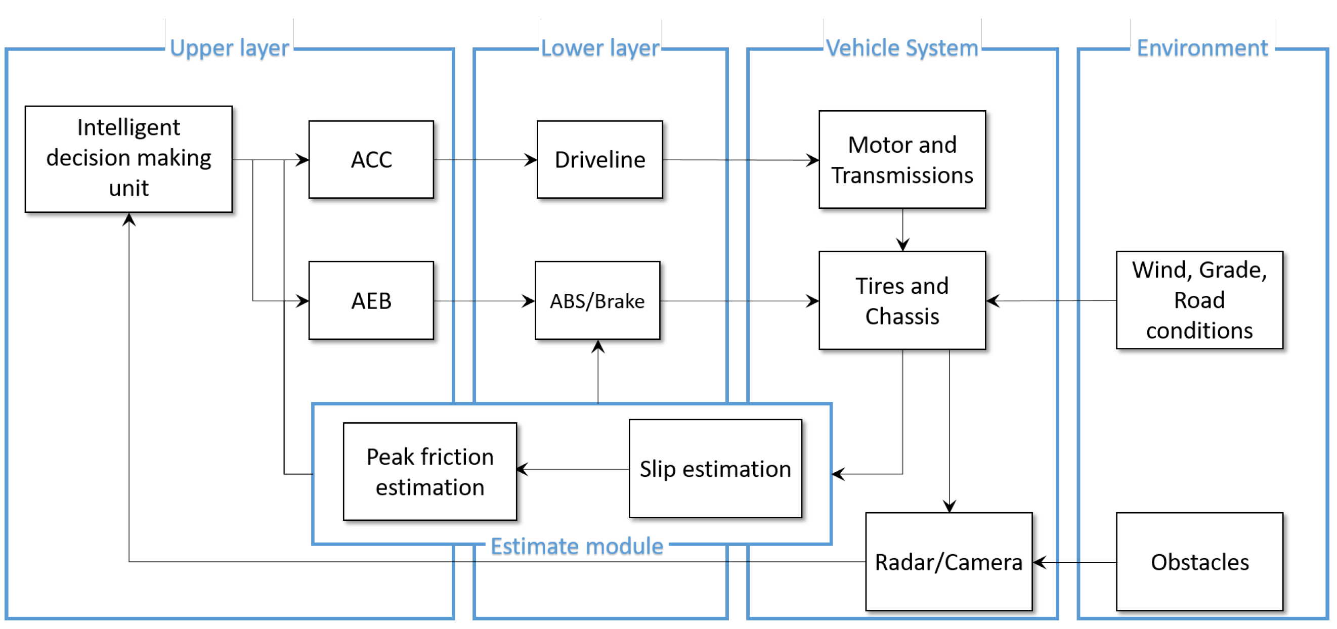
Figure 1. On-board Control Architecture.
Applsci 11 02197 g001
Figure 2. Friction Estimator: Vehicle model and reference system in which the z axis is perpendicular to the road equivalent plane xy.
Applsci 11 02197 g002
Figure 3. Tire characteristics curve and potential friction coefficient.
Applsci 11 02197 g003
Figure 4. Procedure to evaluate potential friction coefficient.
Applsci 11 02197 g004
Figure 5. Architecture of the vehicle state estimation system.
Applsci 11 02197 g005
Figure 6. Co-simulation Platform.
Applsci 11 02197 g006
Figure 7. Road-Grip aware Driving Functionalities: vehicle-following and hard emergency braking. (a) Time-history of the current distance gap, d, and of the desired one, d d e s . (b) Time-history of the ego velocity v and leader velocity v l e a d . (c) On-board road-grip estimate, μ ( t ) vs. μ ^ .
Applsci 11 02197 g007
Figure 8. Road-Grip aware Driving Functionalities: vehicle-following and hard emergency braking. Time-history of the ego-vehicle acceleration (a), jerk (c), front tire (b) and rear tire (d) longitudinal slip ratios.
Applsci 11 02197 g008
Figure 9. Driving Functionalities without on-board road-grip estimate: vehicle-following and hard emergency braking. (a) Time-history of the current distance gap, d, and of the desired one, d d e s . (b) Time-history of the ego velocity v and leader velocity v l e a d .
Applsci 11 02197 g009
Figure 10. Road-Grip aware Driving Functionalities in case of varying μ : vehicle-following and hard emergency braking. (a) Time-history of the current distance gap, d, and of the desired one, d d e s . (b) Time-history of the ego velocity v and leader velocity v l e a d . (c) On-board road-grip estimate, μ ( t ) vs. μ ^ .
Applsci 11 02197 g010
Figure 11. Road-Grip aware Driving Functionalities during Stop&Go. Time-history of the current distance gap, d, and of the desired one, d d e s (a) ego velocity v and leader velocity v l e a d (c) safety index, γ (e) with road grip adaptation. Time-history of the current distance gap, d, and of the desired one, d d e s (b) ego velocity v and leader velocity v l e a d (d) safety index, γ (f) without road grip adaptation.
Applsci 11 02197 g011
Table 1. Ego vehicle parameters used for simulation purposes and control tuning parameters.
ParameterDescriptionValue
mvehicle mass1521 [kg]
I z chassis moment of inertia2875 [kg · m 2 ]
l f distance c.o.g.-front axle1.2 [m]
l r distance c.o.g.-rear axle1.6 [m]
C x longitudinal drag coefficient0.28
I w wheel moment of inertia1 [kg · m 2 ]
R r wheel radius0.315 [m]
hheight c.o.g.0.54 [m]
τ driveline constant0.05 [s]
τ ˜ H headway time1.1 [s]
d 0 minimum spacing2 [m]
T s ACC sampling time0.1 [s]
H p ACC prediction horizon15
H c ACC control horizon15
Δ u m i n ACC minimum control−0.1 [m/s 2 ]
Δ u m a x ACC maximum control0.1 [m/s 2 ]
q 1 ACC spacing tracking weight2
q 2 ACC velocity tracking weight5
q 3 ACC acceleration weight20
q 4 ACC control effort weight20
rACC incremental control effort weight20
Table 2. Summary of the minimal values assumed by the safety indexes in every described scenario.
Scenariomin TTCmin λ min d(t)
Vehicle following with estimation2.02−0.1510.30
Vehicle following w/o estimation0−1.080
Stop&Go with estimation2.731.223.20
Stop&Go w/o estimation2.130.482.70
Publisher’s Note: MDPI stays neutral with regard to jurisdictional claims in published maps and institutional affiliations.