Article

Study on the Leakage and Inter-Stage Pressure Drop Characteristics of Two-Stage Finger Seal

1
School of Mechanical Engineering, Northwestern Polytechnical University, Xi’an 710072, China
2
School of Mechanical and Precision Instrument Engineering, Xi’an University of Technology, Xi’an 710048, China
*
Author to whom correspondence should be addressed.
Appl. Sci. 2021, 11(5), 2239; https://doi.org/10.3390/app11052239
Submission received: 19 January 2021 / Revised: 11 February 2021 / Accepted: 25 February 2021 / Published: 3 March 2021
(This article belongs to the Section Mechanical Engineering)

Abstract

:

Featured Application

Two-stage finger seal is a novel and revolutionary compliant seal, which has the characteristics of high speed, pressure and temperature capacity, low leakage, low cost, and long life time. It can be used in the secondary flow system of aeroengines.

Abstract

To solve the high leakage and high wear problems faced by sealing devices in aeroengines under the condition of high axial pressure difference, the two-stage finger seal is proposed in this paper. The finite element method and computational fluid dynamics (FEM/CFD) coupling iterative algorithm of the two-stage finger seal is developed and validated. Then the performance advantages of two-stage finger seal compared to the one-stage finger seal are studied, as well as the leakage and the inter-stage pressure drop characteristics of two-stage finger seal are investigated. Finally, the measure to improve the inter-stage imbalance of pressure drop of two-stage finger seal is proposed. The results show that the two-stage finger seal has lower leakage and lower contact pressure than the one-stage finger seal at high axial pressure difference, but there exists an inter-stage imbalance of pressure drop. Increasing the axial pressure difference and the root mean square (RMS) roughness of finger element can aggravate the imbalance of pressure drop, while the radial displacement excitation of rotor has little influence on it. The results also indicate that the inter-stage imbalance of pressure drop of the two-stage finger seal can be improved by increasing the number of finger elements of the 1st finger seal and decreasing the number of finger elements of the 2nd finger seal.

1. Introduction

As an important component in an aeroengine, the sealing device has an important influence on its thrust-to-weight ratio and specific fuel consumption. For the large turbofan engine, the erosion and wear of the labyrinth seal in the internal-flow system can lead to an increase of specific fuel consumption of over 1% per year, and the influence on small turbine engines is more serious, as the loss can account for up to 7% in specific fuel consumption and up to 17% in power [1]. In addition, compared with redesigning and requalifying the compressor or turbine structural components to improve the performance of the aeroengine, the adoption of the advanced seal technology has the advantages of low investment and high benefit. Research has shown that the specific fuel consumption can be reduced by 2.5% by using advanced seals at only a few locations [2]. For these reasons, the sealing workers have conducted in-depth exploration and extensive research around the advanced sealing technology of aeroengines in recent years.
Labyrinth seal is one of the most widely used sealing technologies in the history of aeroengines for its simple structure and strong working environment adaptability. However, there must be a enough radial clearance between the radial knives of the seal and the shaft to avoid contact and wear, so the leakage of labyrinth seals is considerably high [3]. Compared to the labyrinth seal, the brush seal has lower leakage, longer lifespan, and better sealing stability, and has been proven to be able to replace the labyrinth seal at key sealing locations in aeroengines [4,5,6]. When the axial pressure difference is relatively high, the bristle stiffening and blow down effect become more prominent, which increase the contact pressure between bristle and rotor, leading to more severe wear of brush seal, therefore, the sealing performance of brush seal degrades [7,8,9]. Finger seal is a new compliant seal, which can adapt to the radial vibration of rotor without damaging the integrity of seal [10]. The measured finger seal leakage is 1/3-1/2 of the traditional labyrinth seal, and the cost of manufacturing is less than 40–50% of the brush seal [5,11]. Therefore, it has been widely considered by sealing researchers. Later, the sealing workers successively proposed the pressure balanced finger seal and the C/C (carbon/carbon) composite finger seal to further improve the sealing performance of the finger seal based on the traditional finger seal design [12,13,14]. Up to now, the theoretical and experimental research on the performance of finger seal has been relatively perfect, and a systematic summary of the research on finger seal has been made by Li [13] and Braun [15].
Although the finger seal has many advantages over the labyrinth seal and brush seal, the hysteresis and wear of finger seal become more and more serious under the condition of high axial pressure difference, so it cannot meet the requirements of modern aeroengines for advanced seal technology. The pressure balanced finger seal can reduce the hysteresis effect, but the contact force between the low pressure finger element and the rotor increases rapidly with the increase of axial pressure difference due to the non-uniform gas force, so the working life of the pressure balanced finger seal cannot be guaranteed under the condition of high axial pressure difference [16]. The C/C composite finger seal with reasonable design can still ensure the sealing performance and working life under the working condition of high axial pressure difference, however, the high cost manufacture limits the price performance ratio, and the C/C composite finger seal is not suitable for operating at high temperature. With the development of the modern aeroengine, the increased pressure ratio, increased temperature, and increased rotational speed which results in higher vibration levels and possible instabilities put forward more requirements for the seals in aeroengines, as the current seals cannot meet the requirements of aeroengines. So it is still the common goal for sealing researchers to seek new sealing structures that can meet the requirements of long life, low leakage, and low manufacturing cost [17].
In a multi-stage seal, step-by-step pressure dividing function makes the axial pressure difference of each stage seal relatively small. If the finger seal is applied to the design of a multi-stage seal, the excellent sealing performance of the finger seal can be fully exerted due to the smaller hysteresis clearance and the lower contact pressure caused by the smaller axial pressure difference. Therefore, the application of the finger seal into a multi-stage seal can solve the problems of high leakage and high wear faced by the traditional finger seal under the condition of high axial pressure difference, so as to further expand the range of application of the finger seal. In view of this, the two-stage finger seal (2SFS) is proposed in this paper. Compared to the one-stage finger seal (1SFS), the structure of 2SFS is more complicated. There exists a strong coupling relationship between the axial pressure difference of each stage seal, and the leakage passages of each stage seal interact with each other. Thereby, the analysis method for 1SFS is no longer applicable to 2SFS. As a new sealing structure, the 2SFS will inevitably be accompanied by the emergence of new physical phenomena. Referring to the research results of multi-stage brush seal [4,18], the inter-stage imbalance of pressure drop may also occur in 2SFS. When the inter-stage imbalance of pressure drop becomes serious, the axial pressure difference of a certain seal in 2SFS is too high, which increases the radial hysteresis clearance and wear, and as a result, the leakage increases and the lifespan decreases. Finally, like the 1SFS, there also exists a side leakage flow for 2SFS, and in order to better predict the leakage and inter-stage pressure drop of 2SFS, the side leakage flow should be considered.
Based on the above analysis, the finite element method and computational fluid dynamics (FEM/CFD) coupling iterative algorithm for analyzing the performance of 2SFS is proposed. The leakage and the inter-stage pressure drop characteristics of 2SFS are studied under various conditions, and the advantages of 2SFS compared to the 1SFS are also discussed under the condition of high axial pressure difference. Finally, the measure to improve the inter-stage imbalance of the pressure drop of 2SFS is presented. The research in this paper can provide the necessary technical support and theoretical basis for the application of 2SFS in aeroengines.

2. Two-Stage Finger Seal Geometry

The 2SFS is developed from the 1SFS. As shown in Figure 1, the 2SFS is mainly composed of two 1SFSs, and each 1SFS is composed of a forward cover plate, an aft cover plate, a spacer, and multi-staggered and superimposed finger elements. The 1SFS on the side of high-pressure cavity is called the 1st finger seal, the 1SFS on the side of the low-pressure cavity is called the 2nd finger seal; the cavity enclosed by two 1SFSs, a rotor, and stator is called the middle-pressure cavity. For the 2SFS investigated in this paper, the two pressure balanced cavities are machined on the aft cover plate of the 1st finger seal, while the pressure balanced cavities, which are not connected with each other and have the same geometrical shape as the finger interstice, are arranged on the aft cover plate of the 2nd finger seal. In addition, the structural parameters of the finger elements of the two 1SFSs are the same, and Table 1 shows the main structural parameters of 2SFS. It should be noted that the seal/rotor radial clearance and the RMS (root mean square) roughness of finger element are 55 μm and 1 μm for the tested seal, while the seal/rotor radial clearance is 0, and the RMS roughness of finger element is 0.5, 1, and 1.5 μm for the numerical seal. Last, the surface of finger elements is usually treated by rough and precision mill, and the material of finger elements is nickel-based superalloy GH4169, whose elastic modulus and Poisson’s ratio are 205 GPa and 0.3; the material of rotor and aft cover plate is cobalt-based superalloy GH605, whose elastic modulus and Poisson’s ratio are 231GPa and 0.286.

3. Analysis Method of Two-Stage Finger Seal Based on FEM/CFD Coupling

3.1. Analysis Scheme

Similar to the 1SFS, the leakage flow of 2SFS is mainly comprised of the main leakage flow (leakage flow through two 1SFS/rotor radial clearances) and the side leakage flow (leakage flow through the two finger stick bundles (set of all the finger sticks)). For main leakage flow, only the radial clearances caused by the hysteresis effect are considered in the analysis, and the finite element method (FEM) is used to calculate the radial hysteresis clearances. For side leakage flow, the porous medium approach is adopted. In the previous study, the authors have equivalently regarded the finger stick bundle of 1SFS as a porous medium [19]. However, as shown in Figure 1, the circumferential width of the finger stick stem (the region of finger stick corresponding to the foot upper circle to the finger base circle) is significantly smaller than the circumferential width of finger foot, the flow resistance of the fluid flowing through the micro-voids in the rough contact interface between adjacent finger feet is much greater than that between adjacent finger stick stems. Therefore, the finger stick bundle of 1SFS is equivalent to two porous media in this paper: A porous medium representing the finger foot bundle (the region of finger stick bundle corresponding to the finger foot) and a porous medium representing the finger stick stem bundle (the region of finger stick bundle corresponding to the finger stick stem).
When the finite element method is used to calculate the radial clearance of each 1SFS caused by the hysteresis effect, it is necessary to take the axial pressure difference of each 1SFS as the input parameters. In addition, for any 1SFS in 2SFS, the contact state between adjacent finger sticks is related to its axial pressure difference. Therefore, when the porous medium models are used to simulate the side leakage flow of 2SFS, the resistance coefficients (including viscous resistance coefficients and inertial resistance coefficients) of porous media are a function of axial pressure difference of 1SFS. However, for 2SFS, the axial pressure difference of each 1SFS is related to the structural and operating parameters, there is no obvious explicit relationship between the axial pressure difference of each 1SFS and the total axial pressure difference of 2SFS, so the axial pressure difference of each 1SFS cannot be directly obtained by the total axial pressure difference of 2SFS. To solve the problem, the FEM/CFD coupling iterative algorithm is proposed to study the leakage and inter-stage pressure drop characteristics of 2SFS in this paper. The calculation flow is as follows.
(1)
Specify the initial axial pressure difference of each 1SFS according to the total axial pressure difference of 2SFS (it is generally assumed that each 1SFS bears the same axial pressure difference).
(2)
Calculate the radial hysteresis clearance of each 1SFS and the resistance coefficients of each porous medium as input parameters of the CFD model of 2SFS.
(3)
Establish the CFD model of 2SFS including main leakage flow and side leakage flow, then calculate the leakage of 2SFS and the axial pressure difference of each 1SFS.
(4)
According to the axial pressure difference of each 1SFS acquired based on step (3), recalculate the radial hysteresis clearance of each 1SFS and the resistance coefficients of each porous medium, then modify the CFD model of 2SFS and recalculate the leakage of 2SFS and the axial pressure difference of each 1SFS.
(5)
Take that the relative error of leakage of 2SFS is less than 0.001 as the convergence criterion. If the convergence criterion is satisfied, the leakage of 2SFS and the axial pressure difference of each 1SFS can be acquired based on the last established CFD model of 2SFS; otherwise, return to step (4).
Figure 2 shows the flowchart of 2SFS performance analysis based on FEM/CFD coupling iterative algorithm. It should be noted here that it takes about 5~8 iterations between coupled solvers to reach convergence, and it takes about 20 CPU-hours for each CFD numerical calculation.

3.2. Finite Element Models of Finger Seal

In this paper, the finite element method is adopted to calculate the radial hysteresis clearance of each 1SFS in 2SFS. In order to reduce the consumption of the computing resource, the hysteresis analysis of 2SFS is transformed into that of the two 1SFSs. Moreover, the pressure balanced cavity structures of the two one-stage fingers are not the same, so it is necessary to build two different finite element models for the hysteresis analysis. Figure 3 shows the two finite element models of the finger seal based on the ANSYS Mechanical 17.0, and the calculation domains of both models include the 5 layers finger elements (including 2 finger sticks), rotor, and aft cover plate.
In this paper, the structural element SOLID 185 is chosen for the present analysis. As shown in Figure 3a, for the 1st finger seal, the main boundary conditions are as follows: (a) The contact pairs between adjacent finger elements, between the low-pressure finger element and the aft cover plate, and between the finger feet and the rotor are established; (b) the full restraint is applied to the outer annulus of finger element and the rear surface of aft cover plate; (c) the two end faces of the rotor in the axial direction are constrained in the z direction; (d) the two sides of rotor in the circumferential direction are constrained in the x direction; (e) the pressure load (the axial pressure difference of the 1st finger seal) is applied to the end face of high-pressure finger element and the end face of low-pressure finger element corresponding to the pressure balanced cavities; (f) the load steps are applied on the outer surface of rotor: The first step is to apply the rotor radial displacement excitation, and the second step is to reset the rotor. Compared with the 1st finger seal, the difference of boundary conditions of the 2nd finger seal is that the pressure load is only applied in the end face of high-pressure finger element, and the pressure load is the net axial pressure load acting on the 2nd finger seal [12].
After the finite element calculation is completed, the radial displacements of all nodes on the bottom of the finger feet are extracted, and the average value is used as the radial hysteresis clearance.

3.3. CFD Model of Two-Stage Finger Seal

3.3.1. Numerical Model

In view of the cyclic symmetric structural characteristics of 2SFS, the circumferential region corresponding to one finger stick is taken as the computational domain of the CFD model of 2SFS. As shown in Figure 4, the CFD model of 2SFS includes the fluid zone composed of high-pressure, middle-pressure, and low-pressure cavities, pressure balanced cavities and radial hysteresis clearance of each 1SFS, as well as the porous zones transformed from the finger stick bundles. Porous zones A and B are used to simulate the flow thorough the finger foot bundles, and porous zones C and D are used to simulate the flow thorough the finger stick stem bundles.
In this paper, the ANSYS-FLUENT software package is used in the CFD analysis. It is assumed that the sealing medium is an ideal compressible gas and the gas flow is turbulent (the maximum Reynolds number is up to ~106). The realizable k-ε model with enhanced wall treatment is used to simulate the turbulent flow. The main boundary conditions of the CFD model of 2SFS are as follows: (a) The pressure-inlet condition is applied in the inlet section of high-pressure cavity and pressure balanced cavities; (b) the pressure-outlet condition is applied in the outlet section of low-pressure cavity; (c) the moving wall is applied in the rotor surface and the rotor speed is specified; (e) the periodic boundary conditions are defined in the two sides in the circumferential direction; (f) the interfaces between fluid zone and porous zone, as well as the interfaces between adjacent porous zones are set to be interior to realize the mutual flow; (g) the rest surfaces are set to be a static wall boundary condition. In addition, the resistance coefficients (viscous and inertial resistance coefficients) are defined in all the porous zones to characterize additional flow resistances when fluid flows through the porous media, so as to simulate the flow through the two finger stick bundles of 2SFS. The calculation of resistance coefficients of porous media will be elaborated in Section 3.3.2.
The mesh generation is carried out using ANSYS Meshing software. As shown in Figure 5, in addition to the porous zone D, the hexahedral mesh element is used in the other computational domains. The meshes near the regions of the rotor surface are very fine to ensure that the y+ values are within their acceptable range, the range of the rotor surface y+ is 0.58~4.35 in the analysis. The number of mesh layers in radial direction of radial hysteresis clearance is set to be 10, and the meshes in porous zones are also finer than that in the fluid zone to better perform the numerical simulations. Finally, several meshes with different densities are tested, and results showed that the mesh with 2.64 million of elements can guarantee the mesh independent solution.

3.3.2. Calculation of Resistance Coefficients of Porous Media

In this paper, the leakage flow through the finger stick bundles is converted into the seepage in porous media. Compared to the flow in a non-porous medium, the flow in a porous medium is subject to additional resistance forces, and the effect of the additional resistance forces can be reflected by adding an additional source term to the fluid momentum equation. According to the theory of non-Darcian porosity model, the additional source term can be described as follows [20].
S i = a i μ u i 1 2 b i ρ | u | u i
where S is the additional source term; a and b are viscous resistance coefficient and inertial resistance coefficient; μ is the dynamic viscosity; ρ is the fluid density; u is the superficial velocity; the subscript i represents the spatial coordinate direction.
For each 1SFS in 2SFS, the calculation methods of resistance coefficients of porous media are the same, therefore, this paper only introduces the calculation method of resistance coefficients of porous media for a 1SFS. As shown in Figure 6, for the porous medium equivalent to finger foot bundle, the flow resistance in the s1 direction (radial direction of 1SFS) is much smaller than that in the other two directions (z1 and n1) (axial and circumferential directions of 1SFS); for the porous medium equivalent to finger stick stem bundle, the flow resistance in the s2 direction (direction from the foot upper circle to the finger base circle along the finger interstice) is also much smaller than that in the other two directions (z2 and n2) (axial direction of 1SFS and direction perpendicular to direction s2 in the axial end face of 1SFS). Therefore, the two porous media have anisotropic structural characteristics and the resistance coefficients of porous media are different in different directions. In addition, the flow resistance of the fluid in the finger foot bundle is greater than that of the fluid in the finger stick stem bundle, so the resistance coefficients of the porous medium equivalent to finger foot bundle is different from that of the porous medium equivalent to finger stick stem bundle.
In Ref. [19], the authors regarded the whole finger stick bundle as a porous medium, and the equations of resistance coefficients were derived by analyzing the flow resistance forces in the rough contact clearance between adjacent finger sticks and the finger interstices. In order to better model the side leakage flow, the finger stick bundle is equivalent to two porous media in this paper. Considering that the derivation process of the equations of resistance coefficients of the two porous media is similar to that shown in Ref. [19], the equations of resistance coefficients of each porous medium will be given directly instead of the derivation process in order to reduce the length of paper.
For the porous medium equivalent to finger foot bundle, the resistance coefficients (az1, an1, as1, bz1, bn1, and bs1) are calculated by
{ a z 1 = 12 ( n 1 ) ( π r o m s ) β z 1 φ h 2 m L z 1 b z 1 = 2.9 ( n 1 ) β z 1 2 L z 1 a n 1 = 24 ( π r o m s ) β n 1 φ h 2 L n 1 b n 1 = 5.8 m β n 1 2 L n 1 a s 1 = 32 h g β s 1 L s 1 d h 2 b s 1 = 0
For the porous medium equivalent to finger stick stem bundle, the resistance coefficients (az2, an2, as2 bz2, bn2, and bs2) are calculated by
{ a z 2 = 6 ( n 1 ) ( f w s ) β z 2 φ h 2 L z 2 b z 2 = 2.9 ( n 1 ) β z 2 2 L z 2 a n 2 = 12 m ( f w s ) β n 2 φ h 2 L n 2 b n 2 = 5.8 m β n 2 2 L n 2 a s 2 = 32 l f β s 2 L s 2 d h 2 b s 2 = 0
in Equations (2) and (3), n is the number of finger elements of 1SFS; dh is the hydraulic diameter of finger interstice; fw is the width of finger stick stem; lf is the length of finger stick stem; Ls2 is the dimension in the s2 direction of porous medium equivalent to finger stick stem bundle, that is, the distance from foot upper circle to finger base circle along the finger interstice; βz1, βn1, βs1, βz2, βn2, and βs2 are proportional coefficients related to the structural and operating parameters of 1SFS, which are calculated by Equation (4); φ is the pressure flow factor, whose equation is shown in Equation (5) [21]; h is the contact clearance between the adjacent finger elements, which is calculated by Equation (6) [22]; Lz1, Ln1, Ls1 are the dimensions of the porous medium equivalent to the finger foot bundle in the directions z1, n1, and s1, and Lz2 and Ln2 are the dimensions of the porous medium equivalent to the finger stick bundle in the directions z2 and n2, which are calculated by Equation (7).
{ β z 1 = π [ ( r o + h g ) 2 r o 2 ] 2 m h g h β n 1 = L z 1 L s 1 ( n 1 ) h g h β s 1 = 8 r o t m d h 2 β z 2 = π [ r e 2 ( r o + h g ) 2 ] h 2 m l f β n 2 = L z 2 L s 2 ( n 1 ) l f h β s 2 = 4 ( f w + s ) t π d h 2
φ = 1 + 3 ( 1 h / σ 0 ) 2 ( 1 3 1 + γ )
{ P c = 0.003 E × 4.4086 × 1 0 - 5 × ( 4.0 h / σ 0 ) 6.804                  h / σ 0 < 4 P c = 0                                                                                                                                                                                                                                            h / σ 0 4
{ L z 1 = L z 2 = n t L n 1 = 2 π r o L s 1 = h g L n 2 = m ( f w + s )
in which, σ0 = (σ2 + σ2)0.5 is the equivalent RMS roughness; γ is the Peklenik number; Pc is the contact pressure between adjacent finger elements; E’ is the equivalent elastic modulus.

4. Validation Work on the Numerical Method
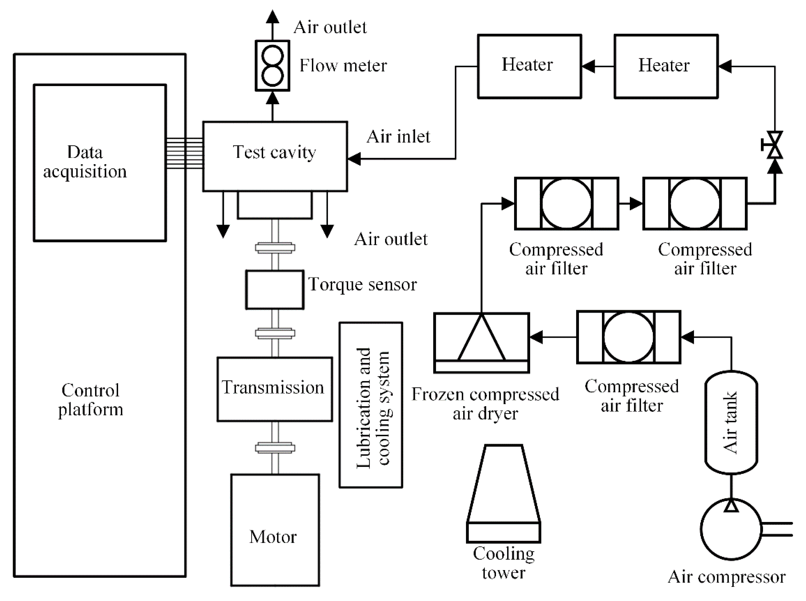
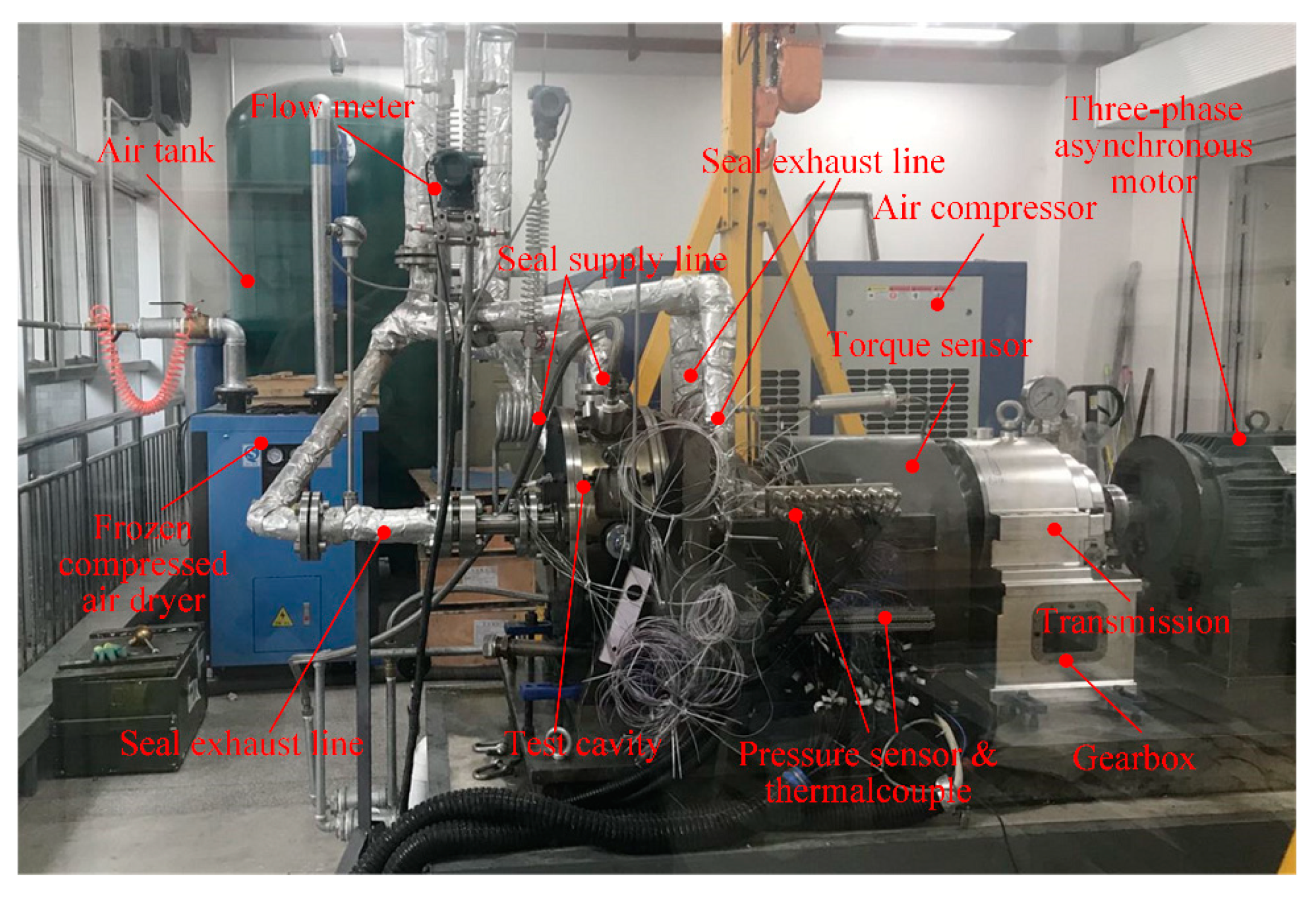
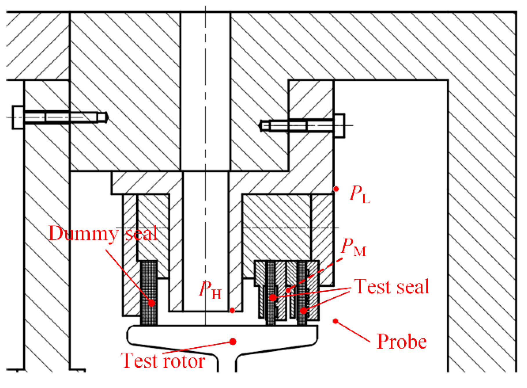
4.1. Test Rig

In order to verify the correctness of the approach based on the FEM/CFD coupling iterative algorithm for analyzing the performance of 2SFS, the leakage and the pressure in middle-pressure cavity were tested on the High-Temperature, Ultra-High-Speed Sealing Test Rig in the Xi’an University of Technology, China, and the experimental results were compared with the numerical results.
As shown in Figure 7 and Figure 8, the test rig is mainly composed of a driving system, an air supply system, a sealing test cavity, a lubrication and cooling system, a data acquisition system, a control system, and some other components. The driving system consists of a three-phase asynchronous motor (YP-50-22-4), transmission, and a high-speed spindle. The rotor is connected to the high-speed spindle with the maximum speed of 45,000 r/min. The air supply system can provide maximum inlet air pressure of 1.05 MPa, and it is composed of air compressor (DAV-90+), air tank, compressed air filter and frozen compressed air dyer, etc. The lubrication and cooling system consists of a gearbox (KCB-55), a two-stage water cooling system and an oil tank, etc. It provides real-time cooling to the bearings and sealing test cavity.
Figure 9 shows the partial cross-sectional view of the sealing test cavity. In the test cavity, the dummy seal and the test seal are installed on both sides of the high-pressure cavity to balance the axial force of air flow. The pressures in the high-pressure cavity, middle-pressure cavity, and low-pressure cavity are measured at the locations presented in Figure 9. For each measurement, there are three probes equally spaced around the circumference. The gas in the low-pressure cavity on the side of the test seal is collected by the flow meter. The photograph of the test 2SFS is presented in Figure 10.

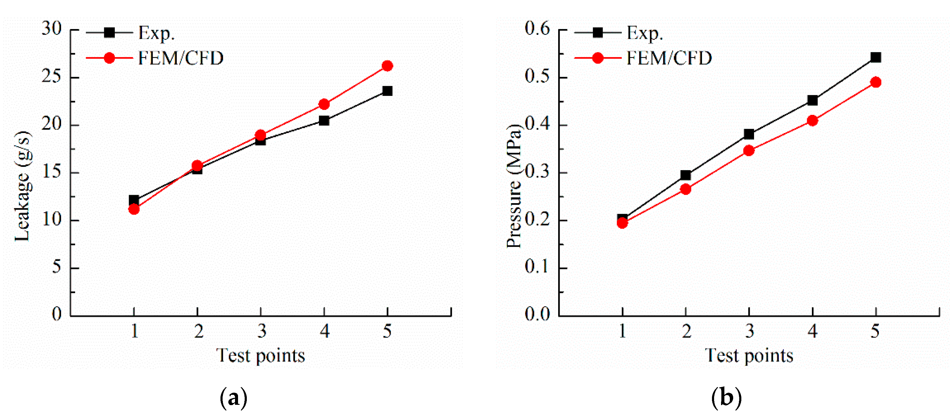
4.2. Comparison between Experimental Results and Numerical Results

In order to better verify the approach based on the FEM/CFD coupling iterative algorithm, the static room temperature experimental results are used to compare with the numerical results. Corresponding to the operating conditions shown in Table 2, Figure 11 presents the comparison between the experimental results and the numerical results.
It can be seen from Figure 11a that the numerical leakage of 2SFS is in good agreement with the tested leakage in general. The results also show that the method built in this paper overestimates the leakage at high axial pressure difference, and this is mainly because the pressure closing effect of finger seal is not considered [11]. When the axial pressure difference is relatively large, the finger/rotor radial clearance decreases due to the pressure closing effect of finger seal, so the tested leakage is lower than the numerical leakage. In Figure 11b, it is clear to see that the numerical predicted pressure in the middle-pressure cavity is less than the experimental results, but the deviation is not obvious. According to the experimental results, the 2nd finger seal bears more axial pressure difference, so the pressure closing effect is more significant, which leads to smaller finger/rotor radial clearance than that of the 1st finger seal. However, the numerical method does not consider the pressure closing effect. As a result, the predicted pressure in middle-pressure cavity is smaller than the experimental results. It can be draw from the above analysis that the method proposed in this paper can predict the leakage performance and pressure drop characteristics of 2SFS with reasonable accuracy.

5. Results and Discussion

In this section, the leakage and inter-stage pressure drop characteristics of 2SFS are investigated, then the way to improve the inter-stage imbalance of pressure drop of 2SFS is developed. All the results are based on the numerical method.

5.1. Leakage Performance of Two-Stage Finger Seal

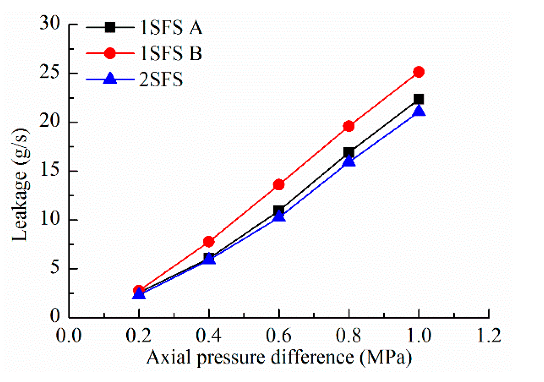
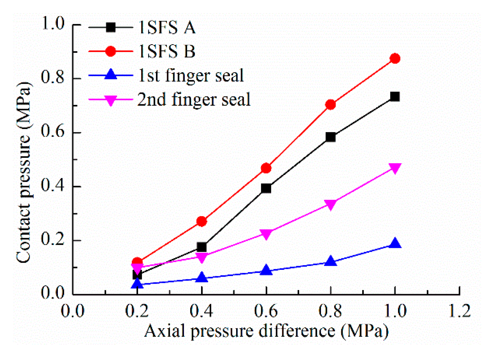
5.1.1. Comparison of One-Stage Finger Seal and Two-Stage Finger Seal

When the radial displacement excitation of rotor is 30 μm, the RMS roughness of finger element is 1 μm, and the rotor speed is 10,000 r/min, the comparison of leakage between 2SFS and 1SFSs under several axial pressure differences is presented in Figure 12. In Figure 12, the aft cover plate of 1SFS A is the same as the 1st finger seal, and the aft cover plate of 1SFS B is the same as the 2nd finger seal. In addition, the structural parameters of finger element of 1SFSs are the same as that of 2SFS, and the number of finger elements is equal to the total number of finger elements of 2SFS.
Compared with the 1SFSs A and B, the 2SFS exhibits lower leakage. The step-by-step pressure dividing function make each 1SFS in 2SFS bear smaller axial pressure difference, which decreases the hysteresis effect, resulting in smaller finger seal/rotor radial clearances, so the main leakage of 2SFS decreases. On the other hand, the side leakage path increases when the axial pressure difference decreases, but the side leakage is much less than the main leakage. Therefore, the 2SFS shows lower leakage than 1SFSs. It can also be seen from Figure 12 that the 2SFS can better improve the leakage performance compared with the 1SFSs under the condition of high axial pressure difference. This is mainly because the step-by-step pressure dividing function of 2SFS has a more significant effect on the hysteresis effect under the condition of high axial pressure difference.
In order to further elaborate the performance advantages of 2SFS compared with 1SFSs, corresponding to the operating conditions shown in Figure 12, Figure 13 shows comparison of contact pressure between 2SFS and 1SFSs. As shown in Figure 13, the contact pressures of the 1st finger seal and the 2nd finger seal in 2SFS are obviously smaller than that of 1SFSs A and B when axial pressure is higher than 0.4 MPa due to the step-by-step pressure dividing function. Although the axial difference of the 1SFS A is larger compared to the 2nd finger seal, the effect of the pressure balanced cavity on the decrease in contact pressure is more significant when the axial pressure difference is 0.2 MPa, so the contact pressure of the 1SFS A is lower at this condition. Further analysis of the data in the figure shows that the contact pressure ratio of the 1st finger seal in 2SFS to the 1SFS A decreases from 0.49 to 0.25, and the contact pressure ratio of the 2nd finger seal in 2SFS to the 1SFS B decreases from 0.84 to 0.54 when the axial pressure difference increases from 0.2 MPa to 1 MPa. Therefore, the 2SFS can greatly improve the working life under the condition of high axial pressure difference.

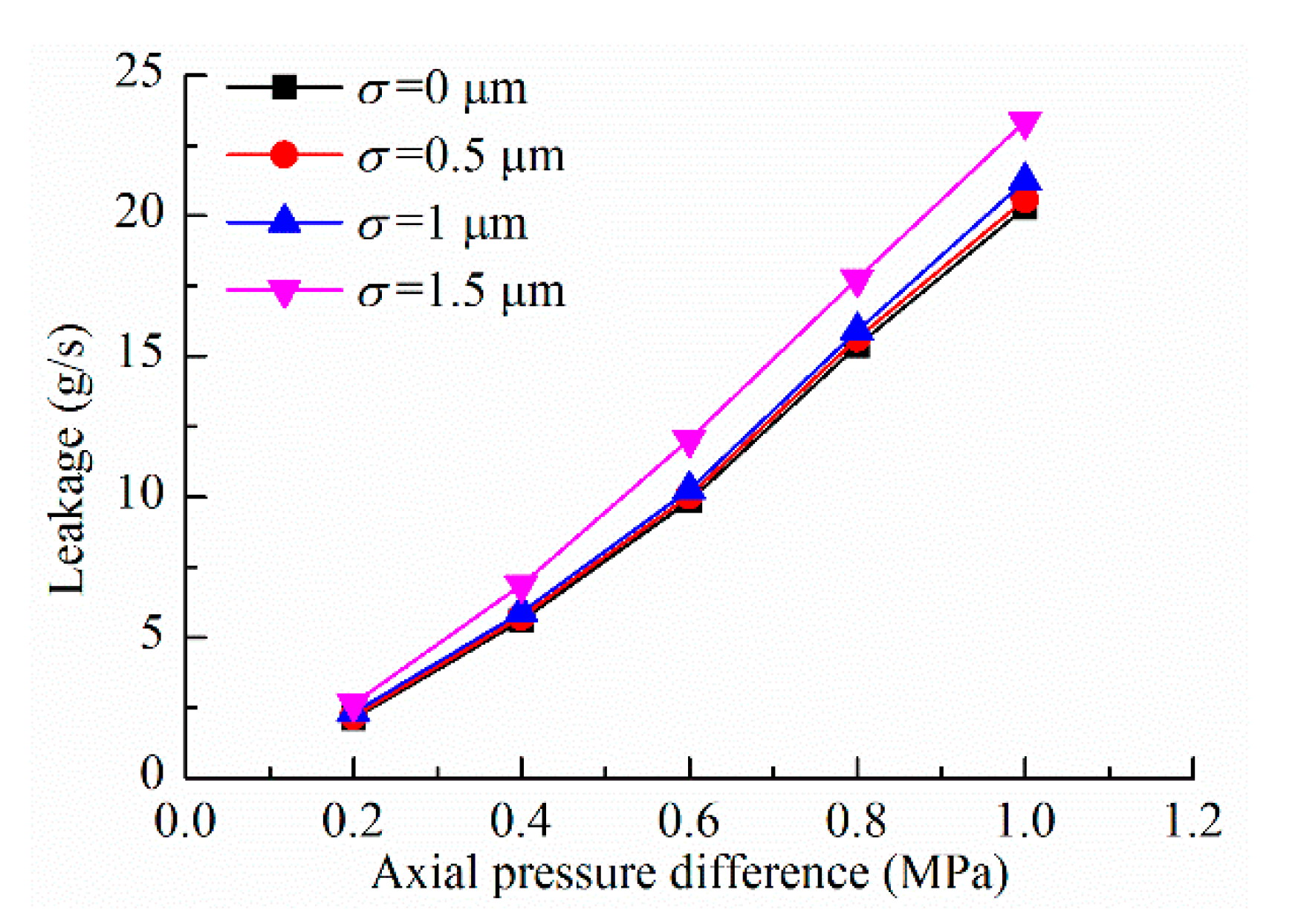
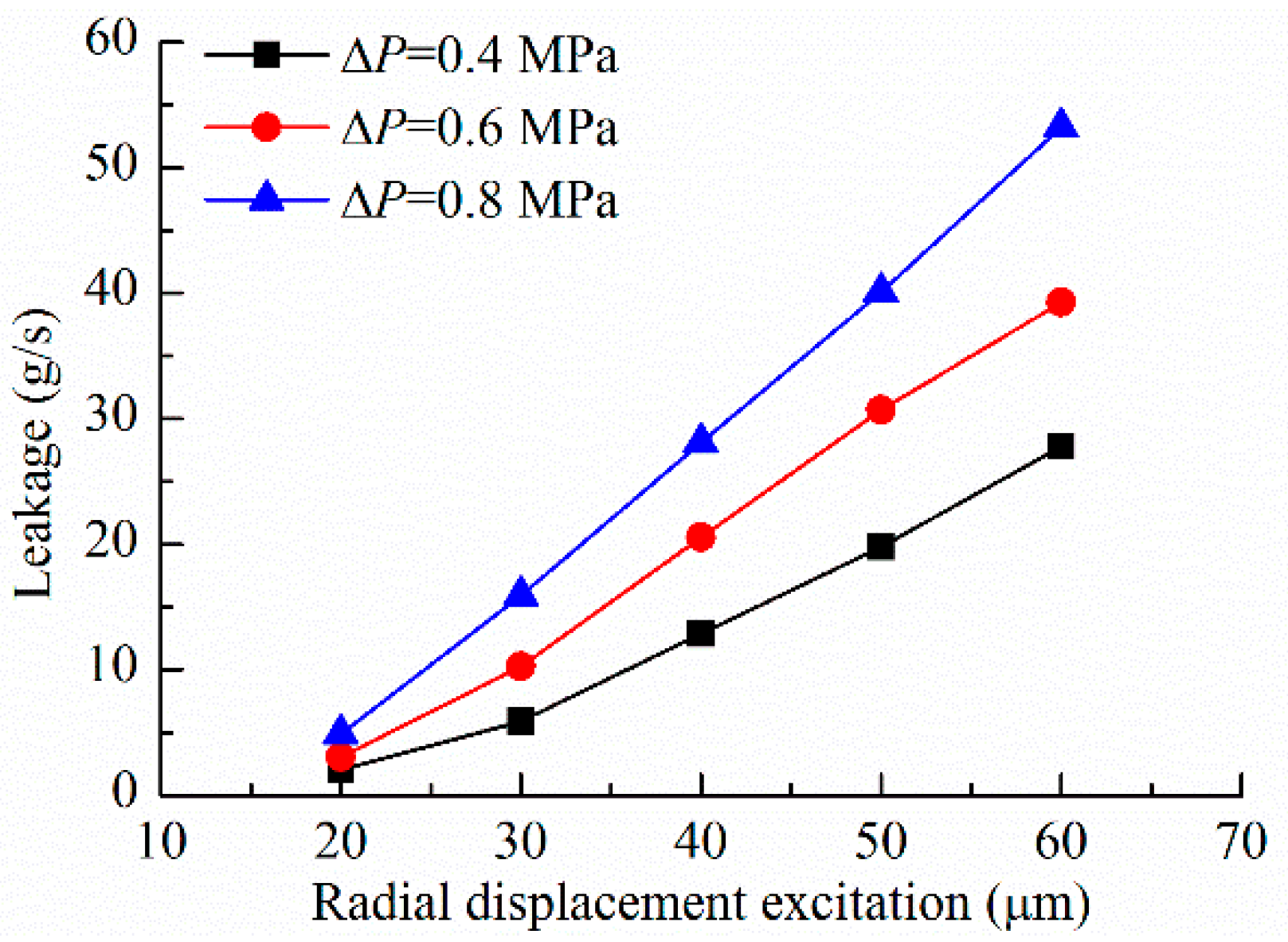
5.1.2. Factors Affecting the Leakage of Two-Stage Finger Seal

It can be seen from Figure 12 that the leakage of 2SFS increases with the increase in axial pressure difference, so this section will not discuss the effect of axial pressure difference on the leakage of 2SFS.
When the radial displacement excitation of rotor is 30 μm and the rotor speed is 10,000 r/min, Figure 14 describes the effect of side leakage flow on the leakage of 2SFS, in which, σ = 0 represents the leakage of 2SFS without considering side leakage flow. When the side leakage flow is considered, the leakage of 2SFS is a little higher, and this is easy to understand. It also can be seen that the difference of leakage of 2SFS is very small whether the side leakage flow is considered or not when the RMS roughness of finger element is small (σ = 0.5), however, when the RMS roughness of finger element is large (σ = 1.5), the influence of the side leakage flow on the leakage of 2SFS cannot be ignored (the relative increment of leakage of 2SFS is more than 15% when the side leakage flow is considered). Therefore, when the surface of finger element is relatively rough, the side leakage flow must be considered to better predict the leakage performance of 2SFS.
When the RMS roughness of finger element is 1 μm and the rotor speed is 10,000 r/min, the effect of radial displacement excitation of rotor on the leakage of 2SFS is shown in Figure 15. It is clear that the leakage of 2SFS increases when the radial displacement excitation of rotor increases. The increasing radial displacement excitation of rotor increases the radial hysteresis clearance of each 1SFS in 2SFS, which results in a stronger main leakage flow, so the leakage of 2SFS increases.

5.2. Inter-Stage Pressure Drop Characteristics of Two-Stage Finger Seal

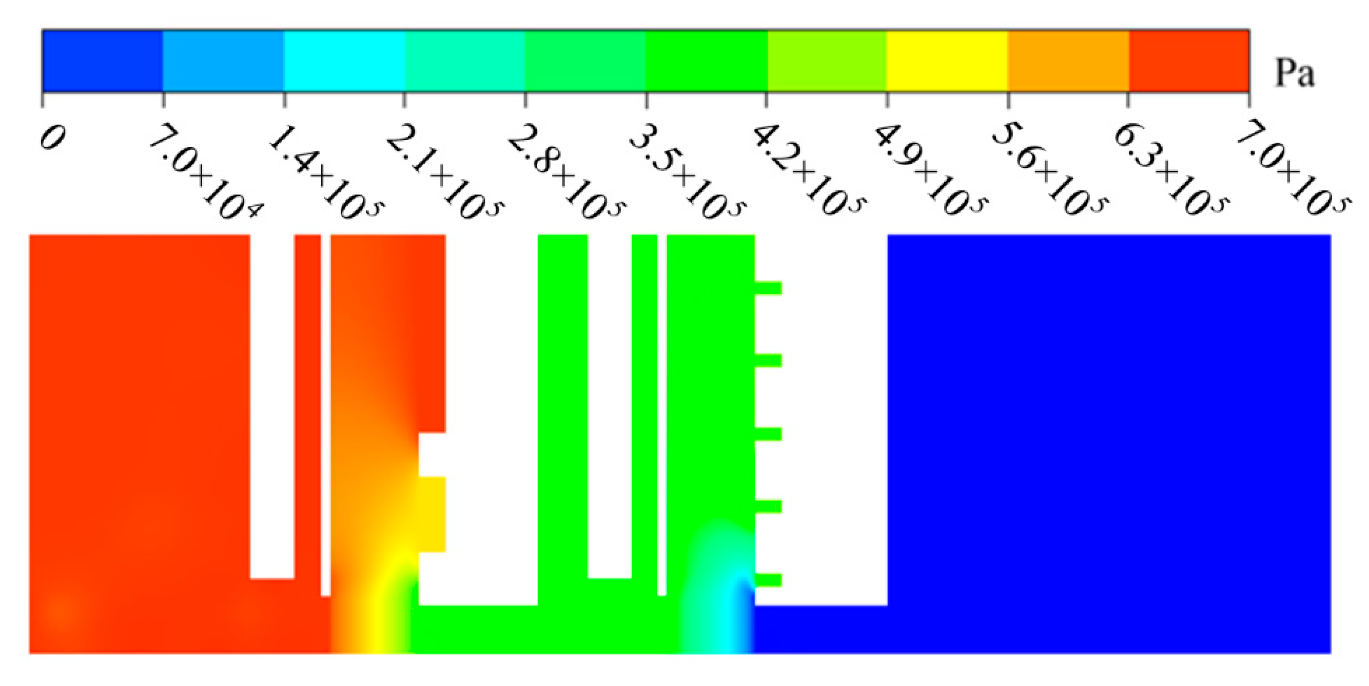
5.2.1. Pressure Distribution of Two-Stage Finger Seal

When the radial displacement excitation of rotor is 30 μm, the RMS roughness of finger element is 1 μm, and the rotor speed is 10,000 r/min, Figure 16 shows the pressure contour of 2SFS under the axial pressure difference of 0.6 MPa, and there exist similar pressure contours under other axial pressure differences. As shown in Figure 16, the fluid pressure in the high-pressure cavity, middle-pressure cavity, and low-pressure cavity changes little, however, when the fluid flows successively through the 1st finger seal and the 2nd finger seal, the pressure decreases step by step due to the high resistances of finger stick bundles. In addition, the fluid pressure changes sharply at the fence height region, especially near the corner of the inner edge of the aft cover plate. The reason is as follows: When the fluid flows out of each finger stick bundle, the flow resistance suddenly decreases, and the fluid accelerates and expands near the corner of inner edge of the aft cover plate, so the fluid pressure changes violently.
In Figure 16, as the axial pressure difference is 0.6 MPa, the pressure drop of the 1st finger seal is 0.233 MPa, while the pressure drop of the 2nd finger seal is 0.367 MPa, so the pressure drop of the 2nd finger seal is 1.575 times of that of the 1st finger seal, which indicates that the 2SFS has a significant pressure drop imbalance between stages

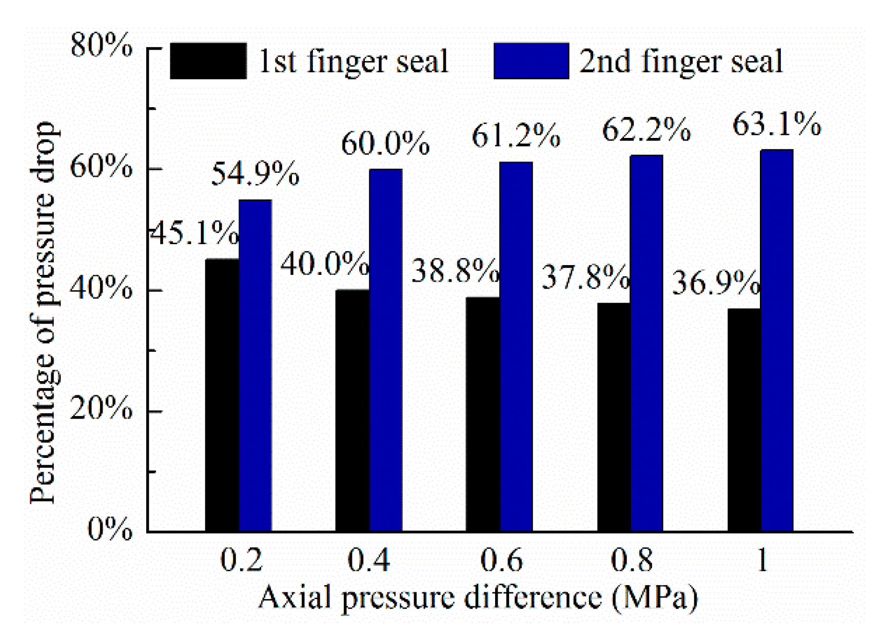
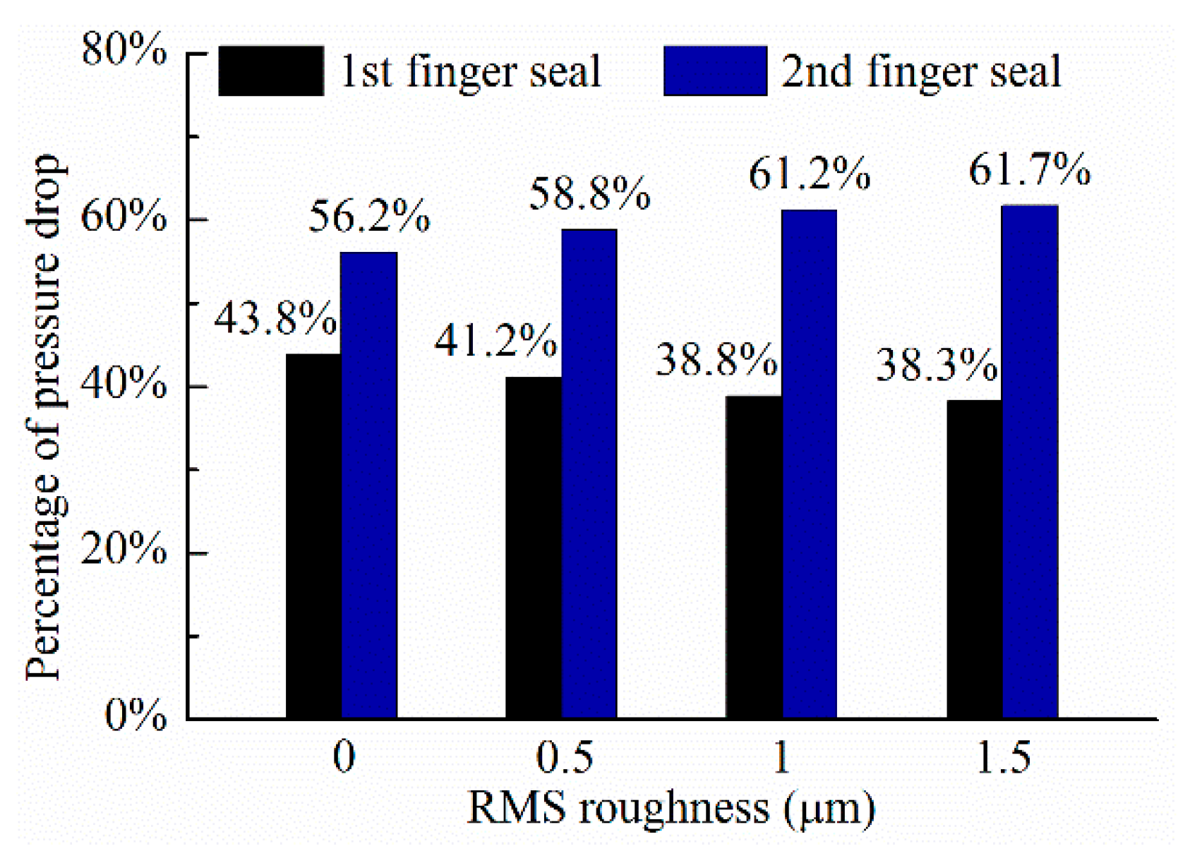
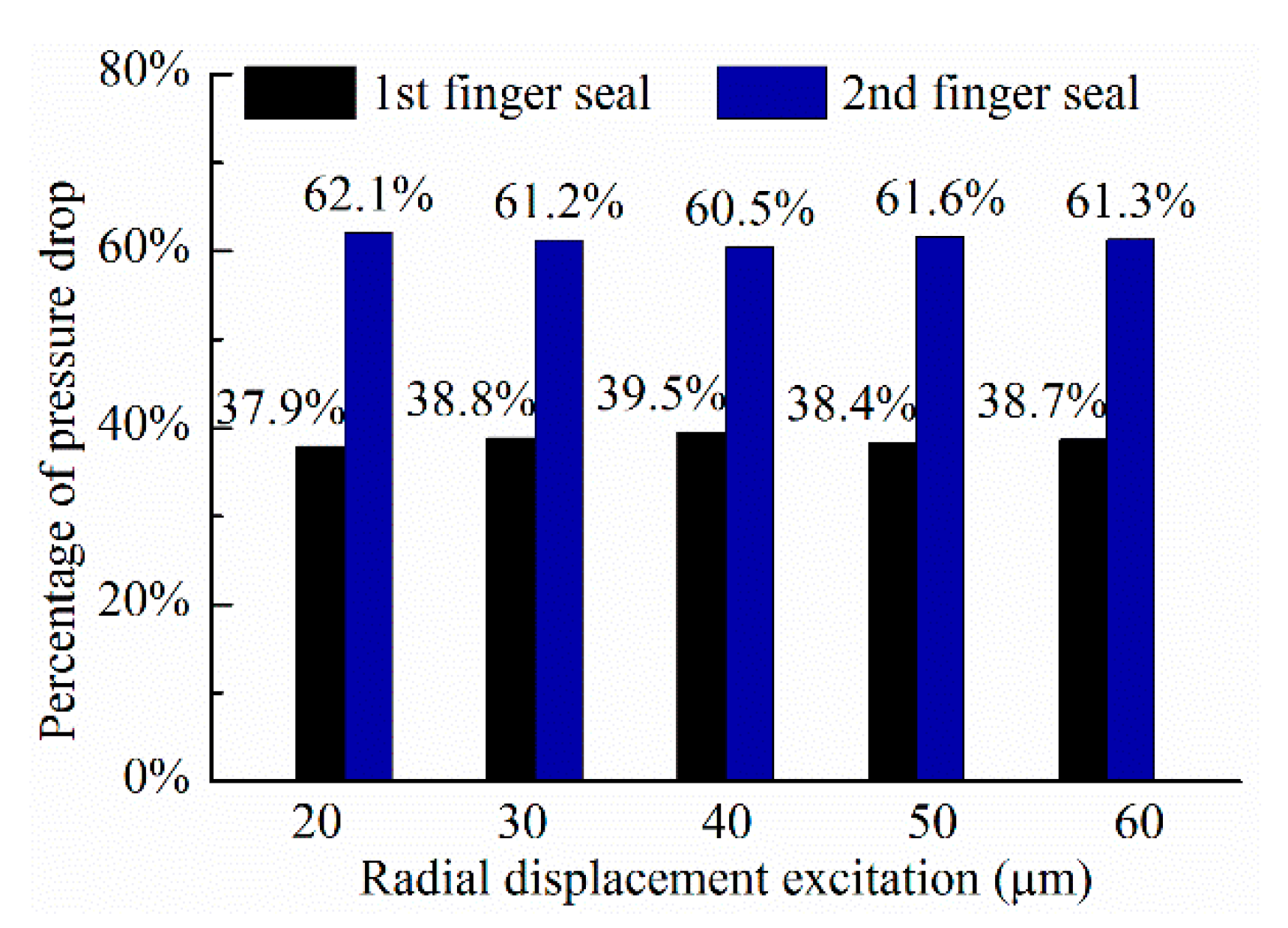
5.2.2. Factors Affecting the Inter-Stage Pressure Drop Characteristics of Two-Stage Finger Seal

When the radial displacement excitation of rotor is 30 μm, the RMS roughness of finger element is 1 μm, and the rotor speed is 10,000 r/min. Figure 17 depicts the effect of the axial pressure difference on the inter-stage pressure drop characteristics of 2SFS. As shown Figure 17, the pressure drop of the 1st finger seal accounts for 36.9–45.1% of the axial pressure difference of 2SFS, the pressure drop of the 2nd finger seal accounts for 54.9–63.1%. The pressure drop percentage of the 1st finger seal is smaller than that of the 2nd finger seal, and the difference increases with increasing axial pressure difference of 2SFS, so it can be concluded that larger axial pressure difference will aggravate the imbalance of pressure drop between stages of 2SFS, which is the same as the two-stage brush seal [23].
When the radial displacement excitation of rotor is 30 μm, the axial pressure difference is 0.6 MPa, and the rotor speed is 10,000 r/min, the effect of side leakage flow on the inter-stage pressure drop characteristics of 2SFS is presented in Figure 18. Compared with not considering the side leakage flow, the percentage of pressure drop of the 1st finger seal is lower when the side leakage flow is considered, and the percentage of pressure drop of the 1st finger seal decreased by 5% when the RMS roughness of finger element is 1 μm. Moreover, as the RMS roughness of finger element increases, the difference between considering side leakage flow and not considering side leakage flow gradually increases. Therefore, it is necessary to consider the side leakage flow when predicting the inter-stage pressure drop characteristics of 2SFS.
When the axial pressure difference is 0.6 MPa, the RMS roughness of finger element is 1 μm, and the rotor speed is 10,000 r/min, Figure 19 shows the effect of radial displacement excitation of rotor on the inter-stage pressure drop characteristics of 2SFS. It is clear to see that the effect of radial displacement excitation of rotor on the inter-stage pressure drop characteristics of 2SFS can be ignored. It indicates that the rotor’s excitation does not affect the inter-stage pressure drop characteristics of 2SFS.

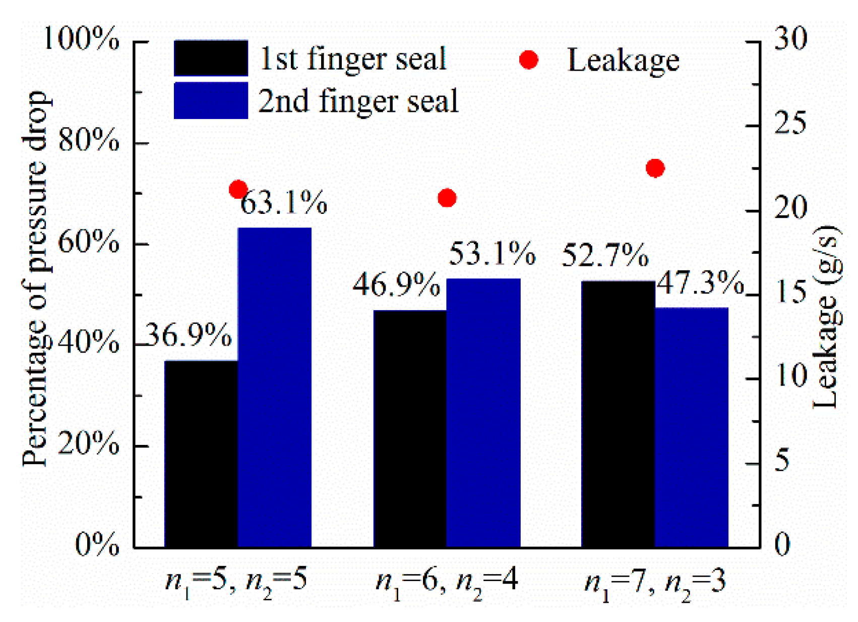
5.2.3. Improvement of the Inter-Stage Imbalance of Pressure Drop of Two-Stage Finger Seal

According to the above analysis results, for the 2SFS investigated in this paper, the pressure drop of the 2nd finger seal is higher than that of the 1st finger seal, especially under high axial pressure difference (1 MPa), the pressure drop of the 2nd finger seal is 1.71 times of that of the 1st finger seal. In view of the high pressure drop of the 2nd finger seal, it’s easy to wear due to the large contact pressure between finger foot and rotor, which not only affects the leakage performance of 2SFS, but is also not beneficial to fully release the performance advantages of low leakage and long working life of 2SFS under high axial pressure difference.
Compared with the structure optimization design of finger element of 2SFS, adopting the existing finger element and reducing the number of finger elements of the 2nd finger seal while increasing the number of finger elements of the 1st finger seal may be one of the very convenient measures to solve the inter-stage imbalance of pressure drop. For this purpose, the pressure distributions of 2SFSs with three kinds of combinations (combination 1: n1 = 5, n2 = 5; combination 2: n1 = 6, n2 = 4; combination 3: n1 = 7, n2 = 3) under the condition of axial pressure difference of 1 MPa are calculated, and the results are shown in Figure 20. It is clear to see that increasing the number of finger elements of the 1st finger seal and decreasing the number of finger elements of the 2nd finger seal can significantly increase the percentage of pressure drop of the 1st finger seal; moreover, the leakage of 2SFS is little affected by the change of the number of finger elements of each 1SFS. Therefore, adjusting the number of finger elements of each 1SFS can improve the inter-stage imbalance of pressure drop with little change in leakage performance.

6. Conclusions

The approach based on the FEM/CFD coupling iterative algorithm is developed for analyzing the performance of 2SFS, and the porous medium model for simulating the side leakage flow of the finger seal is also further improved. On this basis, the performance advantages of the 2SFS compared with the 1SFS are investigated, then the operating parameters and side leakage flow on the leakage and inter-stage pressure drop characteristics are discussed, and finally the way to improve the inter-stage imbalance of pressure drop of 2SFS is studied. The main conclusions are as follows.
(1)
The difference in leakage between 2SFS and 1SFS increases with increasing axial pressure difference, and when the axial pressure difference increases from 0.2 MPa to 1 MPa, the contact pressure ratio of the 1st finger seal in 2SFS to the 1SFS A decreases from 0.49 to 0.25, the contact pressure ratio of the 2nd finger seal in 2SFS to the 1SFS B decreases from 0.84 to 0.54. So the 2SFS has better performance than the 1SFS, and the advantage of the 2SFS compared with the 1SFS is more significant under high axial pressure difference.
(2)
Compared with not considering side leakage flow, the leakage of 2SFS increases when the side leakage flow is considered. When the RMS roughness of finger elements is 1.5 μm, the relative increment of leakage of 2SFS is more than 15%.
(3)
There exists a phenomenon of inter-stage imbalance of pressure drop for 2SFS, and increasing axial pressure difference and the RMS roughness of finger elements will aggravate the imbalance of pressure drop between stages of 2SFS. The radial displacement excitation of rotor has little effect on the inter-stage pressure drop characteristics of 2SFS.
(4)
Increasing the number of finger elements of the 1st finger seal and decreasing the number of finger elements of the 2nd finger seal can improve the inter-stage imbalance of pressure drop of 2SFS with little change in leakage.

Author Contributions

Conceptualization, H.Z. and H.S.; methodology, H.Z. and H.S.; software, H.Z.; validation, Y.Z. and G.C.; formal analysis, H.Z.; investigation, H.Z.; resources, H.Z.; data curation, Y.Z.; writing—original draft preparation, H.Z.; writing—review and editing, G.C.; visualization, H.Z.; supervision, H.S.; project administration, H.S. All authors have read and agreed to the published version of the manuscript.

Funding

This research was funded by National Natural Science Foundation of China, grant numbers 51575445, 51305343.

Institutional Review Board Statement

Not applicable.

Informed Consent Statement

Not applicable.

Data Availability Statement

Not applicable.

Conflicts of Interest

The authors declare no conflict of interest. The funders had no role in the design of the study; in the collection, analyses, or interpretation of data; in the writing of the manuscript, or in the decision to publish the results.

References

  1. Chupp, R.E.; Nelson, P. Evaluation of brush seals for limited-life engines. J. Propuls. Power 1993, 9, 113–118. [Google Scholar] [CrossRef]
  2. Steinetz, B.M.; Hendricks, R.C. Engine seal technology requirements to meet NASA’s Advanced Subsonic Technology program goals. J. Propuls. Power 1996, 12, 786–793. [Google Scholar] [CrossRef] [Green Version]
  3. Marie, H. A study of Non-Contacting Passive-Adaptive Turbine Finger Seal Performance. Ph.D. Thesis, University of Akron, Akron, OH, USA, 2005. [Google Scholar]
  4. Pugachev, A.O.; Deckner, M. Experimental and theoretical rotordynamic stiffness coefficients for a three-stage brush seal. Mech. Syst. Signal Proc. 2012, 31, 143–154. [Google Scholar] [CrossRef]
  5. Chupp, R.E.; Hendricks, R.C.; Lattime, S.B.; Steinetz, B.M. Sealing in Turbomachinery. J. Propuls. Power 2006, 22, 313–349. [Google Scholar] [CrossRef]
  6. Li, H.M.; Braun, M.J. The sealing behavior and force analysis of a double-laminate single-padded finger seal. In Proceedings of the ASME Turbo Expo 2007: Power for Land, Sea, and Air, Montreal, QC, Canada, 14–17 May 2007; pp. 1279–1290. [Google Scholar]
  7. Raben, M.; Friedrichs, J.; Flegler, J. Brush seal frictional heat generation: Test rig design and validation. ASME J. Eng. Gas Turbines Power 2017, 139, 032502. [Google Scholar] [CrossRef]
  8. Huang, S.; Suo, S.; Li, Y.; Wang, Y. Theoretical and experimental investigation on tip forces and temperature distributions of the brush seal coupled aerodynamic force. ASME J. Eng. Gas Turbines Power 2014, 136, 052502. [Google Scholar] [CrossRef]
  9. Pugachev, A.O. Aggregation of experimental and theoretical data for brush seal leakage evaluation. In Proceedings of the 50th AIAA/ASME/SAE/ASEE Joint Propulsion Conference, Cleveland, OH, USA, 28–30 July 2014. [Google Scholar]
  10. Chen, G.D.; Wang, L.N.; Yu, Q.P.; Su, H. Dynamic analysis of C/C composite finger seal. Chin. J. Aeronaut. 2014, 27, 745–758. [Google Scholar] [CrossRef] [Green Version]
  11. Proctor, M.P.; Kumar, A.; Delgado, I.R. High-speed, high-temperature finger seal test results. J. Propuls. Power 2004, 20, 312–318. [Google Scholar] [CrossRef] [Green Version]
  12. Arora, G.K.; Proctor, M.P.; Steinetz, B.M.; Delgado, I.R. Pressure balanced, low hysteresis, finger seal test results. In Proceedings of the 35th Joint Propulsion Conference and Exhibit, Los Angeles, CA, USA, 20–24 June 2014. [Google Scholar]
  13. Li, G.Q.; Zhang, Q.; Guo, L.; Yu, Q.P.; Xu, G.; Zhu, J.Q. Leakage and wear characteristics of finger seal in hot/cold state for aero-engine. Tribol. Int. 2018, 127, 209–218. [Google Scholar]
  14. Lu, F.; Liu, J.; Lu, H. Experimental study on leakage and wear characteristics of C/C composite finger seal. Ind. Lubr. Tribol. 2020, 72, 1133–1138. [Google Scholar] [CrossRef]
  15. Braun, M.J. Finger seal: A compliant seal. In Encyclopedia of Tribology; Wang, Q.J., Chung, Y.W., Eds.; Springer: Boston, MA, USA, 2013; pp. 1106–1131. [Google Scholar]
  16. Gibson, N.; Takeuchi, D.; Hynes, T.; Malak, M. Second generation air-to-air mechanical seal design and performance. In Proceedings of the 47th AIAA/ASME/SAE/ASEE Joint Propulsion Conference and Exhibit, San Diego, CA, USA, 30 July–3 August 2014. [Google Scholar]
  17. Proctor, M.P.; Steinetz, B.M.; Delgado, I.R.; Hendricks, R.C. Turbine Seal Research at NASA GRC; Report No. E-663258; NASA: Cleverland, OH, USA, 2011.
  18. Zhao, H.; Jiao, Z.Z.; Sun, D.; Liu, Y.Q.; Zhan, P.; Xin, Q. Numerical and experimental research on interstage pressure drop distribution affecting factors of multi-stage brush seals. Acta Aeronaut. Astronaut. Sin. 2020, 41, 1–12. [Google Scholar]
  19. Zhao, H.; Su, H.; Chen, G. Analysis of total leakage of finger seal with side leakage flow. Tribol. Int. 2020, 150, 106371. [Google Scholar] [CrossRef]
  20. Dogu, Y.; Aksit, M.F.; Demiroglu, M.; Dinc, O.S. Evaluation of flow behavior for clearance brush seals. ASME J. Eng. Gas Turbines Power 2008, 130, 012507. [Google Scholar] [CrossRef]
  21. Makino, T.; Morohoshi, S.; Taniguchi, S. Application of average flow model to thin film gas lubrication. J. Tribol. 1993, 115, 185–190. [Google Scholar] [CrossRef]
  22. Patir, N. Effects of Surface Roughness on Partial Film Lubrication Using an Average Flow Model Based on Numerical Simulation. Ph.D. Thesis, Northwestern University, Evanston, IL, USA, 1978. [Google Scholar]
  23. Huang, S.Q. Research on the Flow Field and Bristles Tip Contact Heat Transfer Characteristics of Brush Seal. Ph.D. Thesis, Tsinghua University, Beijing, China, 2015. [Google Scholar]
Figure 1. 2SFS design.
Applsci 11 02239 g001
Figure 2. Flowchart of 2SFS performance analysis based on the FEM/CFD coupling iterative algorithm.
Applsci 11 02239 g002
Figure 3. (a) Finite element model of the 1st finger seal and (b) finite element models of the 2nd finger seal.
Applsci 11 02239 g003
Figure 4. Schematic diagram of the CFD model of 2SFS.
Applsci 11 02239 g004
Figure 5. Sample mesh view.
Applsci 11 02239 g005
Figure 6. Principal axis directions of the two porous media equivalent to finger stick bundle.
Applsci 11 02239 g006
Figure 7. Layout of the High-Temperature, Ultra-High-Speed Sealing Test Rig.
Applsci 11 02239 g007
Figure 8. Photograph of the High-Temperature, Ultra-High-Speed Sealing Test Rig.
Applsci 11 02239 g008
Figure 9. Partial schematic diagram of the test cavity.
Applsci 11 02239 g009
Figure 10. Test 2SFS.
Applsci 11 02239 g010
Figure 11. Comparison between the numerical results and the experimental results: (a) Leakage, (b) pressure in middle-pressure cavity.
Applsci 11 02239 g011
Figure 12. Comparison of leakage between 2SFS and 1SFSs.
Applsci 11 02239 g012
Figure 13. Comparison of contact pressure between 2SFS and 1SFSs.
Applsci 11 02239 g013
Figure 14. Effect of side leakage flow on the leakage of 2SFS.
Applsci 11 02239 g014
Figure 15. Effect of radial displacement excitation of rotor on the leakage of 2SFS.
Applsci 11 02239 g015
Figure 16. Pressure contour of 2SFS.
Applsci 11 02239 g016
Figure 17. Effect of axial pressure difference on the inter-stage pressure drop characteristics.
Applsci 11 02239 g017
Figure 18. Effect of side leakage flow on the inter-stage pressure drop characteristics.
Applsci 11 02239 g018
Figure 19. Effect of radial displacement excitation on the inter-stage pressure drop characteristics.
Applsci 11 02239 g019
Figure 20. Effect of number of finger elements of each 1SFS on the inter-stage pressure drop characteristics.
Applsci 11 02239 g020
Table 1. Structural parameters of 2SFS.
ParametersUnitsValues
Base radius of the involute/rbmm20.5
Radius of finger base circle/remm136
Inner radius of finger seal/romm126
Outside radius of finger seal/rwmm141
Finger interstice width/smm0.3
Height of finger foot/hgmm1.25
Thickness of finger element/tmm0.4
Number of finger elements of the 1st finger seal/n1-5
Number of finger elements of the 2nd finger seal/n2-5
Number of finger sticks/m-72
Seal/rotor radial clearanceμm0, 55
RMS roughness of finger element/σμm0.5, 1, 1.5
Table 2. Experimental conditions.
Test Points12345
Pressure in high-pressure cavity/MPa0.3500.4450.5300.6180.698
Pressure in low-pressure cavity/MPa0.1500.1950.2300.2680.298
Publisher’s Note: MDPI stays neutral with regard to jurisdictional claims in published maps and institutional affiliations.

