Abstract
Over the years, building information modelling (BIM) has undergone a significant increase, both in terms of functions and use. This tool can almost completely manage the entire process of design, construction, and management of a building internally. However, it is not able to fully integrate the functions and especially the information needed to conduct a complex energy analysis. Indeed, even if the energy analysis has been integrated into the BIM environment, it still fails to make the most of all the potential offered by building information modelling. The main goals of this study are the analysis of the interaction between BIM and energy simulation, through a review of the main existing commercial tools (available and user-friendly), and the identification and the application of a methodology in a BIM environment by using Graphisoft’s BIM software Archicad and the plug-in for dynamic energy simulation EcoDesigner STAR. The application on a case study gave the possibility to explore the advantages and the limits of these commercial tools and, consequently, to provide some possible improvements. The results of the analysis, satisfactory from a quantitative and qualitative point of view, validated the methodology proposed in this study and highlighted some limitations of the tools used, in particular for the aspects concerning the personalization of heating systems.
1. Introduction
The large-scale diffusion of building information modelling (BIM) tools for architecture has led to an enormous evolution of these digital means [1]. Today, it includes multiple functions capable of carrying out numerous analyses (e.g., structural, energy, metric-estimative, etc.) on a single virtual model of the building. In particular, some aspects, e.g., energy ones can be implemented by using a monitoring system connected to the BIM. Jen-tu and Vernatha [2] proposed an application of Building Information Modelling in establishing the ‘BIM based Energy Management Support System’ (BIM-EMSS) to assist individual departments within universities in their energy management tasks. They installed sensors for occupants and other equipment such as electricity sub-meters that constantly logging consumption, and developing BIM models of all rooms within individual departments’ facilities, data warehouse, building energy management system that provides energy managers with various energy management functions, and energy simulation tools (such as eQuest). In addition, Alahmad et al. [3] integrated BIM with a Real Time Power Monitoring (RTPM) System, and Jeong-Han Woo et al. [4] presented a prototype of BIM-based Baseline Building Model (B3M) for ageing commercial buildings. When the aim is not the real-time monitoring and there is not an existing building or the possibility to install sensors and other devices, it is necessary to use energy simulation tools and connect them with the BIM. Although BIM software is technologically advanced and able to best meet the needs of professionals in various applications, the energy simulation function needs many improvements. Some researches started to investigate the topic of the “green dimension” [5]. Indeed, to optimize the design in terms of energy efficiency, it could be useful that the energy simulation phase be carried out in meantime with the development of the project [6] and to make choices based on intermediate calculations, and therefore constantly modify the project until the objectives are achieved [7]. To do this, it is often necessary to build another digital model, called BEM (Building Energy Model), or implement the BIM model with all the information needed for energy simulation (occupation of the rooms, calculation of thermal bridges, analysis based on hourly climate data, etc.) [8]. The main issue is the lack of bidirectional interaction between the two models. Furthermore, one of the main issues is data transmission. For this reason, BIM for energy simulation is often used only for early design step [9]. The aim should be to work with a unique model [10]. In last decade, many researchers presented studies on BIM’s application in energy analysis and simulation [11] and proposed solutions for the interoperability between BIM and energy simulation tools [12]. Some of them developed tools to integrate BIMs. Bratch et al. [13] evaluated the possibility of integrating a thermal load prediction metamodel to building information models to facilitate the data exchange process. To do this, they developed a tool to validate the viability of this integration using gbXML, and it was submitted to validation tests. Ramaji et al. developed an extension for OpenStudio able to transform building information models represented in Industry Foundation Classes (IFC) files into building energy analysis models in the OpenStudio data format. Kamel et al. [14] developed and presented a new tool called ABEMAT (Automated Building Energy Modelling and Assessment Tool), able to make the building energy simulation using BIM automatic and to give fine-grained outputs. It receives a gbXML file and provides users with the amount of heat transfer through each building envelope element.
Kim et al. [15] developed and validated a library for BIM for the building energy simulation (ModelicaBIM library) using an Object-Oriented Physical Modeling (OOPM) in the scope of the building envelope.
A design-decision-supporting tool for the conceptual phases of design and throughout the design process based on a BIM template has been designed by El Sayary and Omar [16]. In particular, the aim was to develop a simple tool to calculate how many photovoltaic solar panels can be installed to reach a zero-energy building by substituting all electric devices. Xu et al. [17] investigated the application of BIM for addressing the building energy performance gap. The authors provided a clear set of guidelines for how BIM could be used, by each function, to overcome the BEPG to reduce global emissions driven from the building and construction sector. These cited studies provided good outcomes and results. Nevertheless, a goal of this study is to test a commercial existing tool, easy to be found and to be used. Other authors applied existing commercial tools.
Additionally, Utkucun and Sözer [18] proposed a method to determine the interoperability of the utilized programs for evaluating a building’s energy performance and indoor comfort through the BIM approach. To do this, they built three main analysis models: An architecture of the building (with the 3D building model), indoor comfort conditions (with the computational fluid dynamics for natural ventilation simulation), and energy performance (with a building energy model specified by the building architecture and its systems). Then, they integrated them through a BIM platform. In order to investigate the potential and limitations of applying BIM to energy management and simulation in the operation lifecycle phase of a service building, Rodrigues et al. [19] developed a service building BIM model in Autodesk Revit and used Energy Analysis for Autodesk Revit that automatically generated the Building Energy Model (BEM) from the BIM model and performed a cloud-based simulation in Autodesk Green Building Studio (GBS). They found input limitations of GBS, mainly in HVAC systems customization, compromise the representation and energy performance evaluation of the building under actual operating conditions. For this reason, they affirmed that GBS is more adequate for early buildings’ lifecycle stages where energy simulation results may support decisions that aim to improve the buildings’ energy performance during the operation phase.
Tushar et al. [20] used the software Autodesk Revit together with the energy rating tool (FirstRate5), and BIM-enabled life cycle assessment (LCA-Tally) to quantify, compare, and improve the building design options to reduce carbon footprint and energy consumptions in residential dwellings. Alam and Ham [21] compared FirstRate5 with Archicad EcoDesigner developing three building types. They found significant differences between simulations, being, measured areas, thermal loads, and potentially serious shortcomings within FirstRate5, that were discussed along with the future potential of a fully BIM-integrated model for energy rating certification in Victoria. In Farzad Jalaei and Ahmad Jrade’s study [22], an integrated method that links BIM, energy analysis, and cost estimating tools with a green building certification system was presented. The aim was to calculate the potential gain or loss of energy for the building and to evaluate its sustainability based on the US and/or Canadian Green Building Council.
Right now, the data transmission between BIM and BEM is possible through two types of file format: IFC (Industry Foundation Classes) and gbXML (Green Building Extensible Markup Language). Both have important advantages. The IFC format is the standard format for information exchange in BIM modelling and is the only format to have a certification. It is possible to load most of the information concerning a building except for the energy analysis data, such as occupancy profiles, data relating to external and internal temperatures, systems, etc. The gbXML is a format based on IFC, but containing all the information of an energetic nature. It was developed to operate in this field, and it is the most popular among energy analysis software. Indeed, some software have been imported only in this format to the detriment of the IFC (IES-VE [23], EnergyPlus [24], eQUEST [25]). However, in a review paper, Gao et al. [26] investigated the data transfer between BIM to building energy modelling and they found that the development of BIM-based building energy modelling is still at the initial stage and few methods can be guaranteed to generate reliable building energy models from building information models without errors.
In this light, it has to be remembered that the choice of the tool is very important because, based on the software used, working times can increase or be reduced. On the other hand, it is possible that once the BIM model of a building is completed, it is exported to software for energy analysis, and this does not interpret the geometries well or even fails to import a lot of information previously entered. It makes the work useless. In this case, the technician has to manually enter each missing item or in the worst case, he/she has to build a model specifically for the energy analysis. This procedure can be more or less long depending on the building under consideration. It certainly differs from the BIM aim that provides a faster and interoperable workflow by means of a single model.
The most common choice in the architectural-energy field is to proceed with the architectural design and postpone the energy analysis at the end. It provides a separate and specific calculation, and this process often leads to a meaningless analysis as this is ascertained.
The process to be adopted must be the opposite: Support the design with energy analysis from the early stages (which by its nature will be a summary, as you will not yet have all the parameters to be able to make a more complex analysis) and direct the project towards a more eco-sustainable way. In this light, obviously, a real transition, from BIM to BEM is required. It has to be managed by single software that is based on the digital model that is being built, and which automatically updates the BEM on this basis, allowing for a reduction in work-time and a more energy-saving design.
In this study, a methodology based on the full interaction between Graphisoft’s BIM software Archicad and the plug-in for dynamic energy simulation EcoDesigner STAR was tested. They have been selected after a study of the rules on energy analysis, an examination of the operational potential of different software on the market, and a research conducted by a wide scientific community interested in various capacities in issues related to the interaction between architecture and energy analysis. In particular, the choice has been based on some main criteria such as versatility, i.e., the presence of integrated functions that allow BIM and BEM modelling, compliance with standards (the software or plug-in for energy analysis must meet the requirements set by the most advanced energy diagnosis standards, such as UNI EN ISO 52016-1 for the calculation in dynamic hourly regime, ASHRAE 140-2017 and UNI/TS 11300 on the monthly average stationary calculation and certification required by buildingSMART for IFC certification; and versatility thanks to the presence of integrated functions that allow BIM modelling and BEM modelling.
The main goals are the analysis of the interaction between BIM and energy simulation and the identification of a methodology that allows overcoming the above-mentioned limits. With this purpose, Graphisoft’s BIM software Archicad and the plug-in for dynamic energy simulation, EcoDesigner STAR, were used. They have been selected after a careful study of the rules on energy analysis, an examination of the operational potential of different software on the market, and research conducted by a wide scientific community interested in various capacities in issues related to the interaction between architecture and energy analysis. Thanks to the state-of-art analysis, the advantages and the disadvantages of the existing tools were highlighted and compared. The application of the selected tool on an existing case study gave the possibility to further study and to test the methodology. Finally, the analysis of the lacks suggested some improvements that can be done.
2. Methodology of the Study
This study starts from the idea that BEM can be useful for energy analysis building, but there is some issue due to the lack of bidirectional interaction between BIM and BEM, as observed in literature.
This paper aims to study a method to carry out energy analysis using these tools. To do this, it was hypothesized to test a combination of two tools (selected after an investigation of some existing tools doing background research). They were used to perform the experiment (test) that provides information and data. These latter were analyzed and interpreted to formulate the results by including advantages and disadvantages to performing an energy analysis by using the selected tools. In conclusion, the study shows that it is possible to perform energy analysis through the use of BIM, but it needs some improvements.
The research was conducted in several steps. In the first phase, some of the most common new design tools and the most recent standards for energy analysis were studied. From this first analysis, it was possible to list the disadvantages and the advantages. Once a tool was selected that matched the required characteristics, it was validated using a simple building. Then, an existing building was chosen as a case study to apply the energy analysis methodology in a BIM environment. It was defined through the application of a test model. Figure 1 shows the workflow diagram.
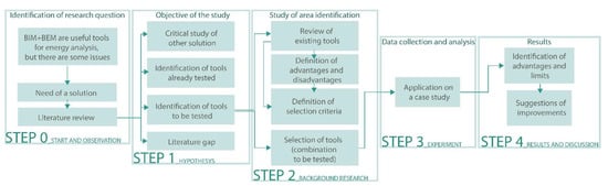
Figure 1.
Workflow diagram with research framework.
The studies conducted in the first phase highlighted one of the main problems that hindered the diffusion and use of energy analysis plug-ins in the BIM environment, namely the lack of integration between the parametric architectural model with information content (BIM, Building Information Model) and the energy model (BEM, Building Energy Model). The problem is the possible loss of information during the conversion from BIM to BEM, or worse, the lack of interpretation of the entire model. It is clear that this problem diverges the actual workflow from the characteristic one of BIM, based on the principle of interoperability, i.e., the possibility that allows different professionals to work and exchange information on a single digital model.
As said, the lack of integration between BIM and BEM means that, during the energy analysis phase, it is necessary to build a new model or implement the Building Information Model with new information not managed by it.
Once the objective of the study was defined, we moved on to research and the choice of software suitable for supporting a working methodology that allows full integration between BIM and BEM already in the design phase. Various digital tools for energy analysis were evaluated, and the choice of the software used in this study was determined by the evaluation of some of its specific characteristics, such as the validity of the calculations (with reference to current legislation) and certifications in the BIM field. To verify the validity of the calculations, a sample building with characteristics suitable for evaluating the effectiveness of the software was simulated.
The last phase of the study was dedicated to applying the digital tool and the methodology defined for the sample model to an existing building. The choice was determined by the value and also by the simplicity of the building, which allows you to control the result of the simulation process more precisely. The simplicity to which reference is made does not concern the spatial and architectural quality of the building or housing, but rather the relationships with the ground and the characteristics of use that allow a more effective control of the results of the BEM energy analysis. The chosen building, in fact, has simple thermal zones, with no particularities (of use or construction) that could alter the calculation of the energy simulation. Finally, based on the detection of the limits and the lacks, some further possible improvements of the tool have been suggested.
3. From BIM to BEM: Advantages and Limitations
The study and the implementation of methods to transform a “BIM” to a “BEM” are a topic always more common in the scientific community. Indeed, BEM has a large number of applications in the most varied cases of energy analysis. Moreover, as said, the available tools have limitations (sometimes highly restrictive). For this reason, technicians are not encouraged to use them. The main identified problem is the transmission of data between the BIM modelling tools and the energy simulation tools. It limits the possibility to operate with the least possible number of digital models.
The main formats are:
- The IFC is the standard format for exchanging information in BIM modelling. It is the only format to have a certification. By using it, it is possible to upload most of the information relating to a building with the exception of data relating to energy analysis (such as occupancy profiles, data relating to external and internal temperatures, systems, etc.);
- the gbXML is a format based on the IFC; it contains all the energy information. It was developed specifically to operate in this field and it is the most popular among energy analysis software. Indeed, some software only allows the import of this format to the detriment of IFC (IES-VE, EnergyPlus, eQUEST).
It is therefore understood that, based on the software used, working times can increase or be reduced to a minimum. It is possible that, once the BIM model of a building is completed, it is exported to software for energy analysis. Sometimes, it happens that it does not interpret the geometries well or even fails to import a lot of information previously entered, effectively making the work already done useless. In this case, the technician has to manually enter each missing item or, in the worst case, he/she has to build a model specifically for the energy analysis. This procedure can be more or less long depending on the building under consideration. This certainly differs from the BIM methodology aim. Indeed, it provides for a faster and interoperable workflow by means of a single model. The most commonly used choice in the architectural-energy field is to proceed with the architectural design and postpone the energy analysis at the end with a separate and specific calculation. Often this process leads to a meaningless analysis as this is ascertained, which was designed with no room for improvement [26]. Obviously, the process to be adopted should be the opposite: Support the design with energy analysis from the early stages (which by its nature will be a summary, as you will not yet have all the parameters to be able to make a more complex analysis) and direct the project towards a more eco-sustainable way. With this in mind, obviously, a real transition from BIM to BEM is required, instantaneous and managed by a single program. It is based on the digital model that is being built. Consequently, the BEM should be automatically updated. This procedure should reduce the time, the energy spent to work, and should allow a more energy-saving design.
4. Short Review on Existing Tools
The quality of the product, the possibilities offered, and the use the user must do influence the diffusion of a certain program. The most famous and common software for BIM are Revit (Autodesk, San Rafael, United States) [27] and ArchiCAD (Graphisoft, Budapest, Ungheria) [28] and then, Allplan (Nemetschek, Munich, Germany) [29], and Edificius [30] (Acca Software, Avellino, Italy) [31]. The tools included in these software are quite similar. They are equivalent to many functions and just a few advantages are different. In all cases, as regards energy diagnosis, the use of one of these tools often is not suitable.
The choices on the market are different, each with its peculiarities, therefore the main characteristics of each software are examined below, giving precedence to the most common BIM software and related plug-ins and then to independent programs.
4.1. Revit
Revit [27] is one of the most popular BIM software, both for its performance and for its compatibility with other programs widely used in the construction sector (also produced by Autodesk). It must be specified in this regard that Revit has not developed great connectivity with software that is not part of the Autodesk suite. It is possible to find compatibility problems even if almost all manufacturers try to interface as much as possible with Revit. Energy diagnosis is allowed through an additional module, Energy Analysis, which integrates the design features of Revit with the analysis features of Autodesk Green Building Studio, an independent cloud service for energy diagnosis based on the DOE-2.2 simulation engine [25] (which complies with the ASHRAE 140-2007 [32] standard).
4.2. ArchiCAD
ArchiCAD [28], developed by the US company Graphisoft, is one of the two most popular software for BIM design and has the IFC certification of buildingSMART. The energy diagnosis can be carried out both by functions integrated into the program and by a plug-in: EcoDesigner STAR. This latter is an integral part of the program itself. Its calculation engine (VIP-Core by StruSoft) operates in compliance with the ASHRAE 140-2007 and ASHRAE 90.1-2007 (LEED Energy) standards. Therefore, it operates in a dynamic regime. The main novelty of the plug-in is the integration of the missing tools in the package of standard tools (such as the calculation of thermal bridges or renewable energy) and the ability to export files in .gbXML and .PHPP format, for easier collaboration between professionals and technicians.
4.3. Allplan
Allplan [29], developed by Nemetschek, is the leading BIM-based software used in Germany. It is among the programs certified by buildingSMART. Regarding the energy functions, it does not have sufficient tools to conduct a correct simulation. So, in 2009, it was implemented with a new module: AX-Energy. This module integrates the software tools allowing it to carry out energy analyses according to Decrees 311/2006 [33] and 115/2008 [34] and UNI/TS 11300-1 [35] and 2 [36] standards, thus relying on an almost stationary, rather than the dynamic, regime.
4.4. Edificius
Edificius [31] is a software produced by ACCA Software. It is the only Italian program to have received the buildingSMART IFC certification. The construction of a BIM model is accompanied, through an external program by the same company, by the construction of a BEM model for the energy analysis of the architectural building. TerMus used the EnergyPlus energy simulation engine based on the ASHRAE 140-2007 standards allowing analysis in a dynamic regime. Unluckily, it is necessary to install a series of modules, each with its own specific function (for example TerMus-PT calculates thermal bridges and mold risk, TerMus-DIM deals with energy diagnosis and improvement interventions, TerMus-PLUS for dynamic calculation and so on).
4.5. Design Builder
Design Builder [37] is an independent program based on the EnergyPlus simulation engine (it is its graphic interface), capable of analyzing a building under dynamic conditions from the energy point of view. The software has 3D modelling tools, but it is still possible to import into it a model built with an external program compressed in .gbXML format. Since it is not a software used purely for parametric modelling, it does not have the buildingSMART IFC certification.
4.6. Open Studio
Open Studio [38] is another graphical interface of the EnergyPlus simulation engine. It is available as a plug-in for the 3D modeling program SketchUp, with the particularity of being free. Being a SketchUp plug-in, its modelling is more intuitive than other programs with the same function (the IFC certificate is missing), while the analysis tools are not as intuitive as those of other software.
4.7. Simergy
Simergy [39] was developed as an independent program. It uses the EnergyPlus simulation engine, thus operating at a dynamic speed. Its user-friendly graphic interface is particularly effective for its use as a calculation tool, while the 3D modelling integrated in it is not easy and immediate to use. A peculiarity of the software is the possibility of comparing different project hypotheses with relative analyses. Additionally, in this case, since it is not a tool for parametric modelling, the IFC certification is absent.
4.8. TermoLOG
TermoLOG [40], by Logical Soft, is independent software that integrates parametric modelling tools and energy diagnosis. There is the possibility to import models in IFC format built with other programs. As a parametric modelling tool, it does not have buildingSMART certification. According to the standards dictated by UNI EN ISO 52016 [41], and validated by the Politecnico di Milano according to ASHRAE 140-2017 [32], it operates with a dynamic hourly engine (CENED + 2.0).
4.9. EcoDesigner Star
EcoDesigner Star [42] is a plug-in integrated into the ArchiCAD software. It is a graphical interface of the VIP-Core calculation engine optimized to work in harmony with the design tool in a BIM environment. This ArchiCAD extension was created with the aim of facilitating the design of buildings, directing them immediately towards more sustainable solutions. It is therefore a design tool and it does not allow the certification of buildings according to Italian standards. So, in this case, certification must be carried out using analysis software mainly dedicated to it. However, it is specified that the software calculations are not to be considered incorrect or non-compliant with current standards. In fact, they are based on data and specific parameters relating to the ASHRAE standard, and in the input phase, these parameters can be modified in order to obtain results in line with current legislation. It is not possible to carry out immediately and automatically to check required by the regulations.
The novelty proposed with EcoDesigner STAR is to have, within a software in a BIM environment, a powerful energy analysis tool. It is possible to work on a single Building Information Model and transform it almost instantly into a Building Energy Model ready to be analyzed. Moreover, it is also possible to orient the design of a building towards more sustainable ways both from the point of view of energy consumption and that of energy production through renewable sources. From the early stages of the project, an energy analysis can be obtained by defining the parameters necessary for the calculation. Therefore, an overview of the performance of the building and guide the designer towards the best-integrated design solution can be carried out. Using this tool, the path to be explored is established, and after having decided all the details of the building envelope and systems, it is possible to proceed with a further analysis, this time more detailed, to know the behavior of the building through a calculation dynamic, on an hourly basis. The integrated plug-in has many advantages, e.g., the possibility to manage the workflow in an optimal manner, and guarantees, both in terms of parameter input and in the output phase, high versatility and a high degree of data customization. EcoDesigner STAR, through the tools already present in ArchiCAD and connected to it, in the input phase allows you to:
- To build a BEM model from the BIM model, with the definition of thermal zones. They are automatically detected, as well as all the constructive elements that delimit them (walls, floors, doors, windows, beams, pillars, etc.); they can be viewed in 3D, both as an overall volume and as specific elements with their properties (e.g., by selecting a wall, it is possible to access all the parameters that define it, including the thermo-physical properties and orientation);
- to select built materials, with related thermophysical properties, from a large catalogue, or insert new ones with customized parameters, while maintaining the possibility of changing the assigned parameters; these changes are automatically sent to the BEM;
- to geo-localize the building by entering its geographical coordinates, to set the north and the elevation with respect to the sea level with the identification (automatic or manual) of the quote 0; the information entered can be verified through a link with Google Maps that indicates the position just defined;
- to define precisely both the surroundings of the building, by entering the type of land with its thermo-physical properties, the wind and sun shields present, the climatic data, such as air temperature, relative humidity, solar radiation, and wind speed; they can be displayed graphically through monthly, weekly, daily, or hourly charts; (downloading them directly from the dedicated server);
- to add thermal blocks to defined thermal zones that can be inserted; they are characterized not only by the zones, but also by heating, cooling, and ventilation systems, and by operation profiles. The systems that can be inserted are different, all already present in a plug-in catalogue, but new ones can be added based on the type of those present; the operation profiles are also already present in good quantity in the plug-in library, but new ones can be added, customizing them in each of their parameters;
- to define the energy vectors and their costs;
- to calculate according to a finite element approach (FEM) the thermal bridges present in the construction. It is possible using the “Detail” tool of ArchiCAD, which extracts a 2D drawing from a plan or section of the project. In addition, it is possible to make changes both in terms of geometry and materials and finally calculate the thermal bridges through a special window, saving both the numerical data and the temperature or heat flow graphs. Each thermal bridge can then be connected to the thermal block to which it refers;
- to perform a solar analysis on each frame of the building with the creation of a graph; it allows us to understand when the frame in question is exposed to the sun and in what percentage;
In the output phase, it is possible to obtain:
- An illustrative report of the performed energy analysis. It includes a first part that includes all the data common to the entire project (e.g., general graphs on the building’s consumption and energy inputs);
- an excel spread sheet containing, in an extensive and detailed way, all the information that makes up the report;
- a file format different from the ArchiCAD ones, such as .gbXML, PHPP, and a format compatible with VIP-Energy, for exporting the Building Energy Model within other programs for energy analysis or certification. It is also possible to export the project as a “reference building” in order to make a comparison, during the energy simulation phase, between two alternatives of the same project.
4.10. Selection Criteria and Choice of Software
The criterion that led to the choice of the specific software is based on the following characteristics:
- Versatility, i.e., the presence of integrated functions that allow BIM modelling and BEM modelling; the software for BIM modelling can be combined with a well-integrated plug-in for energy analysis. In this way, it is possible to import and export building 2D drawings, BIM modelling and 3D visualization, quasi-static energy diagnosis, dynamic energy diagnosis, calculation of thermal bridges, and calculation of renewable energy sources. The importance of this parameter is given by the significant limitation of errors and simplifications that may arise from the management of the model with different software;
- certification: The BIM software must meet the validity requirements required by buildingSMART for IFC certification;
- in compliance with standards: The software or plug-in for energy analysis meets the requirements of the most advanced energy diagnosis standards, such as UNI EN ISO 52016-1 [41] for the calculation in dynamic hourly regime, and ASHRAE 140-2017 [32] and UNI/TS 11300 [35] on the monthly average stationary calculation.
The following table shows the BIM and BEM software and plug-ins already mentioned in the previous paragraph. For each of them, the greater or lesser compliance with the criteria described above is reported.
Table 1 shows the comparison of the eight examined software.

Table 1.
Comparison of eight examined tools.
The first important difference concerns the IFC certifications. Indeed, it can be seen that only the BIM software combined with the plug-in has the third requirement (e.g., the buildingSMART certification).
The stand-alone BEM software, even if equipped with tools for the construction of a BIM model, cannot match the software dedicated to BIM in terms of functions, interoperability, and complexity. The adoption of the BIM Software + plug-in combination can guarantee a faster workflow. It is free from possible simplifications or misinterpretations of the data, resulting from exporting to external software from a different software house. Moreover, regarding the compliance of the software with the parameter relating to compliance with current legislation, many of them do not operate according to the Italian guidelines for stationary and dynamic calculation. Nevertheless, the 8 software examined comply (except for Allplan) with the ASHRAE 140-2007 standards relating to the validity of the calculation adopted. This does not mean that the calculation tools are wrong, but that these programs can only be used for energy diagnosis. For the compilation of energy performance certificates (APE) and other certification documents, different software has to be used. From the examination of these two parameters, the choice can be restricted to a more limited number of software. The BIM + plug-in software solutions that meet the requirements include:
- Termus (even if the latter is not really a plug-in but a program to complement the first and completely compatible), which allows you to produce documents valid in Italy;
- ArchiCAD + Ecodesigner STAR and Revit + Energy Analysis, which have a similar range of features, but do not produce documents conforming to Italian standards.
Among the stand-alone plug-in, TermoLOG appears to be the more complete than the competitors Design Builder, Open Studio, and Simergy, based on the EnergyPlus calculation engine, and therefore quite similar. Therefore, the main parameter to choose it is the versatility, or the presence of all functions in a single work environment, in order to limit the use of other software.
The versatility suggested adopting an integrated BIM + BEM plug-in solution. It offers a much larger package of features and greater interoperability than the stand-alone solution offered by TermoLOG. Furthermore, Revit + Energy Analysis package is not the best choice according to its versatility. Indeed, it needs to be accompanied by other plug-ins (such as Insight for solar analysis) to work. Finally, for these reasons, the ArchiCAD + Ecodesigner STAR combination has been selected. The parametric modelling of ArchiCAD has been implemented and updated. The model can guarantee full compatibility with the EcoDesigner Star plug-in, making the transition from the BIM model to the BEM model almost instantaneous. The adopted solution solves one of the most common problems in the integration between energy and BIM. Indeed, if the BIM model is imported and interpreted without errors or excessive simplifications, the BEM can be built and obtained by simply enriching the information present in BIM from the Energy Analysis Program. If the import/verification step does not take place correctly, it will be necessary to perform a specific BEM modelling. It causes longer time of work and more effort by the designer. Thus, it nullifies the advantages of the BIM workflow. If the model was correctly set, the ArchiCAD + Ecodesigner STAR solution automatically performs the transition from the BIM model to the BEM model. It has the great advantage of not losing any information present in the BIM and recording in real time in the BEM model all the changes made to the BIM model. It enhances the aim of BIM design.
These considerations can be summarized in graphs in Figure 2.
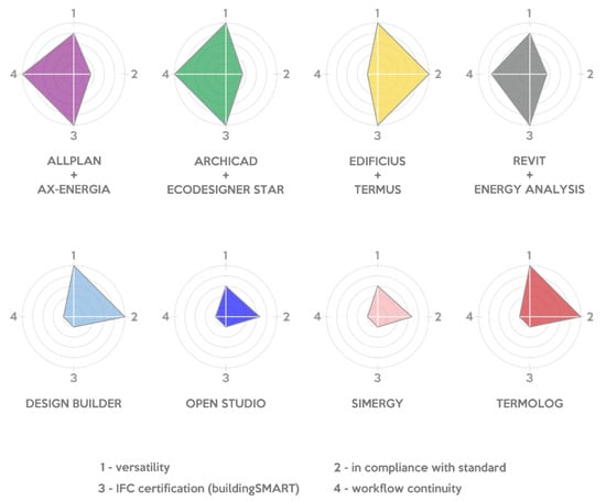
Figure 2.
Comparison of the analyzed tools.
Each figure represents a tool. The vertexes are four main characteristics: Versatility, compliance with the standards, certification, and the “workflow-continuity”. This latter identified the advantage of not having to open another software to conduct energy analysis. It leads to less interoperability since the changes made to the BIM will not be directly reported in BEM. The value related to the “versatility” was associated according to the number of features available (e.g., Open Studio has 3/5 features, so the value of its versatility is 0.6). The value related to the “compliance with the standard” was calculated according to the number of standards complied with, e.g., Allplan + AX-Energia complies with 1/3 standards, so the value is 0.33. The value of the certification is equal to 1, if the tool is certified, and 0 if it is not certified. The value of the workflow-continuity is equal to 1, if the tool has this characteristic, and 0 if it does not.
5. Modelling and Pre-Analysis of a Simplified Building
As a first step, the energy analysis of an apartment in a three-story building was carried out to study the characteristics of the software using EcoDesigner STAR, a plug-in for ArchiCAD. It allowed highlighting the main calculation characteristics and detecting the first advantages and disadvantages of using this tool.
The choice was determined by the value and also by the simplicity of the building, which allows us to control the result of the simulation process more precisely.
The structure is made up of a reinforced concrete frame made of rectangular section beams and pillars (30 × 60 cm). The indoor walls are composed of non-insulated brick blocks. It was geo-located in the city of Palermo. As regards the immediate surroundings, it was decided to consider it not bordering other buildings.
The construction of the BIM model was carried out using the construction components and materials already present in the program library. In this way, possible conflict situations were avoided to better control the process. Figure 3 shows the three-dimensional view of the building with the apartment examined in evidence.
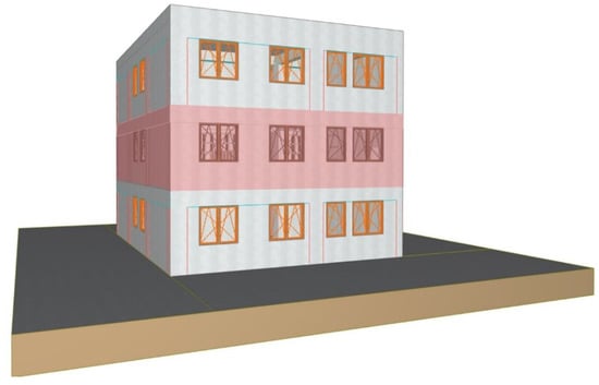
Figure 3.
Three-dimensional view of the building with the apartment examined in evidence.
5.1. Switching to the Building Energy Model
Once the BIM model was obtained, the missing information was implemented for the construction of the BEM model. In particular, data related to the project site and its location with related climatic data (air temperature, relative humidity, solar radiation, and analysis of wind speed and direction) were included. The software can download automatically the information from the Strusoft Climate Server. The Strusoft server bases its climate data on those provided by “Reanalysis NCEP” available on the website of the “NOAA-Cires Climate Diagnosis Center”. The information obtained was compared with the climatic data used by the EnergyPlus calculation engine. It is based on the data collection commonly known as “IGDG—Climatic data G. De Giorgio” [43] (Figure 4).
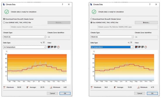
Figure 4.
On the left the climatic data obtained from the Strusoft server, on the right the climatic data G. De Giorgio.
The comparison shows that the climatic data used by the EcoDesigner STAR calculation engine are in compliance with those used by the EnergyPlus calculation engine, with maximum and minimum temperatures very close to each other:
- Maximum temperature: 36.9 °C—minimum temperature 4.62 °C (Strusoft);
- maximum temperature: 34.0 °C—minimum temperature 4.79 °C (EnergyPlus).
It was supposed that the slight deviations between the monthly temperatures were due to the different time intervals relied on for data collection. In particular, the EnergyPlus data refer to a period ranging from 1951 to 1970; while those of the Strusoft servers are updated from 1948 to today. Then, the areas of the building characterized by the same orientation, by the same usage profile and above all by the same system (thermal blocks) were defined (Figure 5). It was possible to identify only two thermal blocks (Figure 4): that of the heated rooms and that of the unheated rooms.
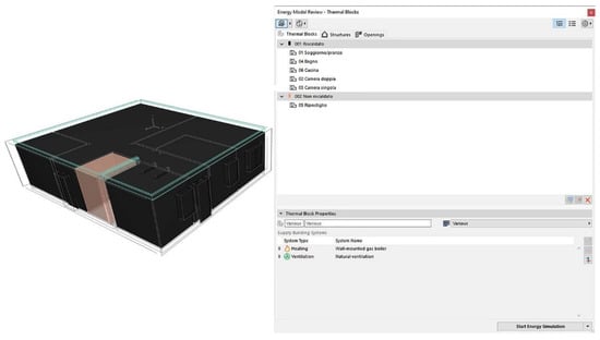
Figure 5.
Screen of the thermal blocks window with 3D visualization of the selected zones.
For each block, an operating profile and a plant system (heating, air conditioning, and ventilation) were set. The software includes different operating profiles (residential, commercial activity, hotel, cinema, museum, and others), but it was chosen to have a more complete overview of the program and its potential, to create a new one. As for the most common software, it is possible to select different schedules for different seasons: One for the summer season (for the cooling plant) and one for the winter season (for the heating plant).
It is possible to assign several thermal blocks to a single system or to assign a specific one to a single thermal block. In particular, it is possible to set the use of a boiler for heating and the production of domestic hot water to several thermal blocks; while the cooling system is, if made with single units serving only one room at a time, it must be assigned for each air-conditioned block. In this case, there is only a natural gas boiler for heating and the production of domestic hot water. Furthermore, there is no type of summer air conditioning and the ventilation is natural as it is normally the case in common homes.
The data relating to the autonomous heating system are very simplified. It is possible to select the nominal power of the element, the type of control (with internal/external sensor or by manual ignition), the type of energy source used, the cost of the energy used, in order to obtain an estimate of the costs and consumption of that particular system. On the other hand, the items relating to terminals are completely missing.
It is not possible to set the number of terminals and their performance. They can be inserted as elements within the model, but they do not interface with the plug-in during the calculation. For a more accurate analysis, it should be necessary to use an external program that includes these attributes. In general, the number of parameters that can be selected is less than the parameters available in the most common software for energy analysis.
For natural ventilation, the parameters to be set are accompanied by an hourly schedule. In this case, it was set to keep the “system” active all year round. In the case of mechanical ventilation, it is certainly useful for calibrating the best usage profile. In addition, it is also necessary to specify the air changes by choosing from four different units of measurement. Furthermore, it is possible to select a function that uses automatically the standard ASHRAE values.
Once all the elements of the building and their materials are set, it is possible to conduct the calculation of the thermal bridges. Before proceeding with the calculations, the plug-in updates the model with the latest changes and automatically detects errors or warnings, which, if not resolved, do not allow it to continue with the simulation. Solving any errors and starting the simulation, EcoDesigner STAR compiles a final report of the simulation.
5.2. First Results of the Analysis
According to the aim of this paper, some advantages and disadvantages were detected already in this step. The main advantages are:
- Automatic construction of the BEM starting from BIM: The model obtained contains in itself a lot of fundamental information for energy analysis, so a few other parameters must be integrated;
- constant updating: Any type of modification made on the BIM model is automatically reflected in the BEM and in the EcoDesigner STAR cards, without any loss of information;
- reliability: The climatic data of the Strusoft server comply with other types of data used by certified analysis programs (see EnergyPlus); furthermore, the calculations are consistent with the parameters set and the result, for example, in terms of consumption, and is plausible if compared with similar buildings;
- good definition of the parameters: The thermo-physical attributes on which one can act are many, allowing us to represent even the most complex elements;
- optimized workflow: Thanks to the use of a single software and a single type of file, it is possible to work quickly and accurately without the loss of data that may occur in the passage of the file from one program to another. Furthermore, all EcoDesigner STAR tools are best calibrated to operate without conflicts with those present in ArchiCAD;
- design support: This tool is not to be used a-posteriori, or after the project is finished, to know only its behavior from an energy point of view. It must be used during the design phase to ensure the maximum result in terms of performance; so, the final simulation refers to a building designed in a truly sustainable way.
Even if they are not many and do not affect the use of the program, some constraints were found and listed following:
- Poor definition of the parameters relating to the systems (especially heating);
- and therefore, it is not possible to insert the calculation of terminals of any kind or the performance of the heating systems. It makes the calculation of these aspects more limited. For this reason, further investigations with other programs should be carried if necessary.
- A separate reasoning must be made for thermal bridges. They are connected to the ArchiCAD Detail tool and they are configured as separate 2D drawings. If a material or a type of construction element changes, the individual modification must be made on the detail and the thermal bridge recalculated. Generally, this operation is not long and it is easy, but for large architectural complexes with numerous thermal bridges where changes need to be made, it is long and hard.
6. Application of the Methodology on an Existing Case Study
In order to verify their correctness, the procedures for the energy analysis in the BIM environment, developed on a sample building, have been tested on a sample building. Indeed, only a building complete in all its parts can provide the necessary information, especially from the plant engineering point of view. Furthermore, in an existing building, the systems have already been measured and have precise characteristics. They can be traced back by recovering the technical sheets drawn up by the manufacturers. The research of the case study was conducted by preliminarily defining some characteristics that the case study building must possess. The aim was to validate the methodology and the final results of the energy simulation. These features are:
- End use: The residential end-use is the one of greatest application interest, as well because many policies aimed to reduce consumption of residential architecture;
- simplicity of the case study: Both in terms of geometric or constructive characteristics, in terms of thermal zones and for the absence of peculiar characteristics (e.g., underground habitable rooms, large glazed areas, or systems designed ad hoc and different from the more common types);
- size: It is a medium size building. It implies the exclusion of individual housing units exposed to the external environment on all sides (this condition would prevent testing all the potential of the software), i.e., large apartment complexes consisting of a few thermal zones, but repeated for several floors (in this case there would be a large amount of data, not very significant from the point of view of the calculation), i.e., considering a 7-storey condominium, in the calculation phase, the significant floors are the ground floor that exchanges heat with the ground, the floor that borders two heated rooms both above and below, and the top floor that exchanges heat with the outside through the cover. For the purposes of this study, it would be enough to consider only one of the 5 floors bordering heated rooms. A good compromise is therefore offered by buildings with two (or rather three) elevations above ground;
- building envelope and thermal plants: All the information about stratigraphy, fixtures, and materials were known or can be inferred with a good approximation;
- it is an existing building.
6.1. Case Study Modelling
As said, this case study was selected as an important sample of existing architecture characterized by the main data available, and, as well in this case, for simplicity. This latter concerns both the spatial and architectural quality of the building or housing, and the relationships with the ground and the characteristics of use that allow more effective control of the BEM energy analysis. The chosen building, in fact, has simple thermal zones, with no particularities (of use or construction) that can alter the calculation of the energy simulation. It is characterized by a simple structure, and a regular plan, with essential thermal zones (with a common residential type of user profile). It is a residential building and has three apartments distributed over three floors above ground connected by an external staircase. Only the apartment on the first floor was chosen.
It must be specified that some simplifications regarding the articulation of the architectural and climate artefact can be made, where necessary, to ensure greater control over data processing by the software. Moreover, some simplifications, e.g., regarding the articulation of the architectural and climate artefact, were made. It endured greater control over data processing by the software.
The selected building met all the necessary characteristics: The Langham House Close residential complex in Richmond (England), designed by James Stirling.
The apartment building consists of 18 residential units. They are spread over three elevations above ground (6 per floor). There are 3 different types of apartments, all based on the same floor plan, which differ in the number of rooms:
- 3 apartments with one bedroom (approx. 65 m2);
- 9 apartments with two bedrooms (approx. 75 m2);
- 6 apartments with three bedrooms (approx. 85 m2).
The three smaller apartments, all on the ground floor, are identical to the apartments with two bedrooms. One of the rooms is intended for the service of condominiums, as an accessory storage. There are also three two-bedroom apartments on the ground floor. On the next floor, there are three two-bedroom apartments and three three-bedroom apartments; the same distribution is repeated on the second and last floor.
At each level, a pair of housing units are served by a common stairwell; one block includes 6 apartments on 3 levels, served by a stairwell; the residential complex consists of 3 blocks (Figure 6 and Figure 7).
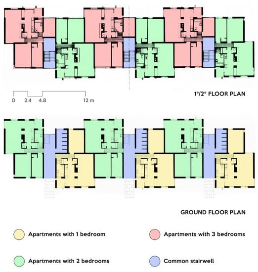
Figure 6.
Plans of the building.
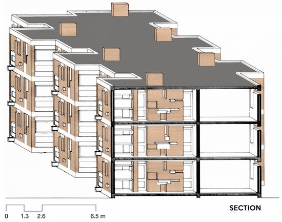
Figure 7.
Section of the building.
The complex is located in a suburban area of London, characterized by a low population density and a strong natural presence; the residential complex is open on all fronts and is surrounded by trees [44].
The entire structure is in load-bearing masonry, consisting of solid bricks (215 × 102.5 × 65 mm) and 10 mm lime mortar joints. The wall structures are differentiated into three types:
- The external perimeter walls are cavity walls, very recurrent in English houses of the first half of the twentieth century; they have an overall thickness of about 270 mm (solid brick of 102.5 mm—air gap of about 65 mm—solid brick of 102.5 mm);
- the internal perimeter walls separate the apartments from each other and from the staircase body; they are entirely in solid bricks without cavities and have a thickness of 215 mm (length of a single brick);
- the internal dividing walls are the partitions of the houses, formed by individual courses of bricks (102.5 mm thick).
Each apartment is characterized by the presence of a central block, where the fireplace is located, and the plant room; this block is in load-bearing masonry and plays a decisive role in the load-bearing structure of the building.
Regarding the structure, the load-bearing masonry is combined with reinforced concrete beams characterized by a rectangular section (27 × 35 cm). They work as curbs for the distribution of loads of the upper floors. Outside, the elevations are characterized by the alternation between brick and concrete. In addition to the beams, visible directly from the outside, there are other reinforced concrete elements, such as the U-shaped gargoyles, the ventilation openings, and the panels under the windows. These latter serve to further stiffen the floors, linking the masonry with the reinforced concrete of the beams and floors [45].
The floors are reinforced slabs, made together with the beams and panels under the windows. Their stratigraphy, described from bottom to top, varies according to the reference plane:
- Ground floor slab: This slab rests directly on the ground and is composed of a bed of compacted materials (generally stones, bricks, concrete) of about 20 cm thick, by a 15 cm cast-in-situ reinforced concrete slab, by a layer of bitumen, from a 3 cm screed, from a 1 cm floor, mainly made of wood and stoneware;
- floor slab: 1–1.5 cm lime-based plaster, 15 cm cast-in-situ reinforced concrete slab, bitumen layer, 3 cm screed, 1 cm flooring (wood or stoneware);
- roof slab: 1–1.5 cm lime-based plaster, 12.5 cm cast-in-situ reinforced concrete slab, 3.5 cm screed, bituminous sheath;
The fixtures are very similar to those envisaged in the project and consist of wooden frames, painted white, with single glass.
Regarding the plants, it must be noted that this building, like many others built in the 1950s, was not originally equipped with heating or cooling systems. The control of the internal temperature was therefore obtained through natural ventilation. In the winter season, the heating of the rooms was performed by a wood-burning fireplace in each single house in the living area. Over the years, with the change in technology, product costs, and lifestyles, each home has been equipped with a heating system. The individual owners carried out the construction of the systems independently. For this reason, the components of the systems (boiler, radiators) vary from apartment to apartment. The solution adopted provides, in general, the installation of an autonomous internal boiler of about 24 kW in the central masonry body. The boiler allows the production of domestic hot water and the power supply of the terminals located in each room of the apartment. The terminals are standard radiators. Given the differences between the apartments, a schematic was adopted in the calculation phase, considering the system of a typical accommodation and then applying it to the other apartments examined. Therefore, small differences (model or commercial brand of the radiator, for example) were eliminated, given that they did not affect the calculation results.
The fireplace is present in all apartments, but its function changes, e.g., in some cases, it is not used. Its function is performed by the heating system (Figure 8). In other cases, residents decided to continue to use it in combination with the heating system, maintaining the wood supply, and others replaced the wood-burning fireplace with a gas fireplace that replaces the radiators in the living area.
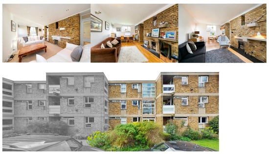
Figure 8.
Pictures of the flat with a gas-fireplace and a wood-fireplace (above) and a picture of the external part of the building with the analyzed part (below).
Figure 8 shows pictures of the flat with a gas-fireplace and a wood-fireplace and a picture of the external part of the building with the analyzed part. The cooling systems have never been installed because they are not necessary because the climate in London in the summer is not very hot. Furthermore, it should also be considered that the building is located in a well-ventilated area, far from the densely built urban center.
The present study examined a single block consisting of 6 apartments, distributed in pairs, on three elevations, and served by a common staircase. The limitation to a single block of apartments does not affect the search results. It respects the modularity desired by Stirling and excludes the repetition of identical elements, superfluous for the purposes of the calculation. The delimitation required the modification of the perimeter walls of the housing: The walls that previously bordered other apartments, in solid bricks, were transformed into cavity walls bordering the external environment, as is already the case for the rest of the construction.
The modelling process was conducted on the basis of two-dimensional graphic references (plans, sections, elevations) produced through the redesign of the project drawings and the verification of the relative congruence (between plan and section, for example); the modelling phase was conducted, as required by BIM, specifying the material and construction characteristics of the individual elements and also the parameters useful for the energy simulation. An accurate BIM model of the building, defined in its architectural-construction aspects, was developed. From the model, it is possible to extract plans and sections, or inspect the building in three-dimensional views.
To export the model from the Building Information Model (Figure 9) and to import it into the Building Energy Model, it is necessary to create the thermal zones to which each room is assigned. This operation, easy and immediate from an operational point of view, requires particular attention from a conceptual point of view.
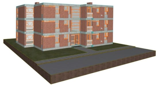
Figure 9.
Navigable virtual model, view of the main front.
For the Stirling building, 7 thermal blocks were identified (Figure 10), one for each of the 6 apartments, and one for the common areas. The thermal block referred to an apartment, contains within it as many thermal zones as there are rooms that compose it. Indeed, all the rooms are heated by the same system and therefore share the same internal temperature. Furthermore, since this is a residence, the occupancy will also be homogeneous throughout the apartment.
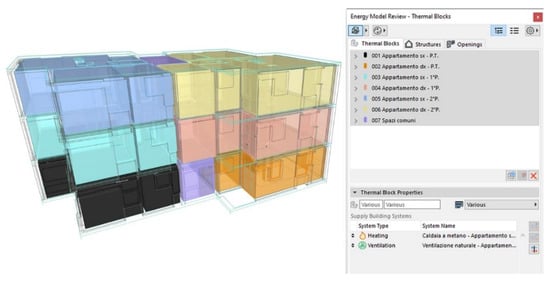
Figure 10.
Graphic visualization of the Building Energy Model (BEM) model with chromatic distinction of the thermal blocks.
Common areas do not have any type of heating and have a different occupancy profile from that of the apartments. After verifying the correct definition of the Building Energy Model, it is possible to proceed to enrich its information content. The operations carried out within the three EcoDesigner STAR tabs are: Thermal Blocks, Structures, and Openings. Within the thermal block section, it is possible to modify the operation profiles of each thermal block with related heating and ventilation systems, to determine, during the calculation phase, the thermal inputs deriving from external and internal factors. The analysis on the operation profiles was calibrated on the basis of a typical English family. The schedules were set including the differentiation of the types of use over the different seasons and working and non-working days. To identify the period of operation of the heating system, the graphs on the climatic data generated by the software were examined. It is thus determined that the apartment is inhabited for a few hours a day during work and school days and that, consequently, systems, lights, and appliances will be active for a few hours. On the other hand, the occupation during non-working days is different, when the apartment is occupied for most of the day, generating a more intensive use of systems, lights, and appliances.
A deep study made it possible to trace in detail the characteristics and technical data sheets of the elements that compose it (Figure 11). Similarly to the operation profiles setting, heating and ventilation systems must be assigned to each thermal block.
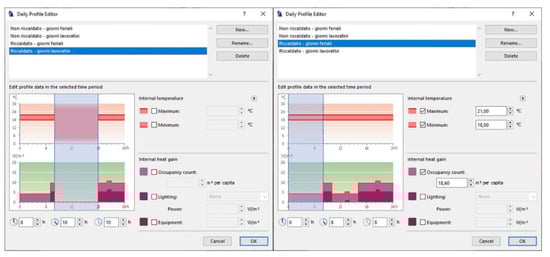
Figure 11.
Schedules of the operation profiles. Note how the occupation of the houses changes between working and school days (left) and non-working days (right) within the period of the year in which the heating is activated.
EcoDesigner STAR, as already specified above, does not provide for the insertion of the heating system terminals (radiators); therefore, only the parameters relating to the boiler (nominal power and flow and return temperatures) and the production of domestic hot water have been entered. Figure 12 shows the window in which the flow and return temperature of the heating system water is set and the energy source used to power the boiler.
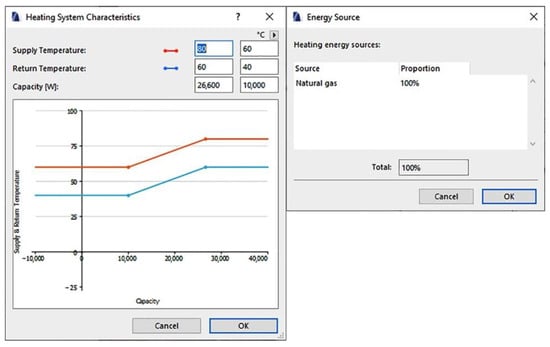
Figure 12.
On the left, the window in which the flow and return temperature of the heating system water is set; on the left, the energy source used to power the boiler.
The ventilation of the apartments is natural. Therefore, it was possible to set parameters such as the number of air changes per hour (defined as ACH—Air Changes per Hour) and the program for using the fixtures. The air exchange has been set with a value of 0.5 ACH. For the attribution of this value, the harsh climate was considered.
The tab called “Structures” can be used to insert and calculate thermal bridges.
The software manages the calculation of the thermal bridge in an extremely intuitive way:
- With the Detail tool, it is possible to isolate the desired portion of the drawing in an independent tab;
- the 2D drawing is graphically improved and the materials are attributed to the various screens representing the construction elements;
- through a dedicated command, the calculation of the thermal bridge is started and takes place in several phases: (i) In the first phase, the area relating to the external air is selected with its temperature (already calculated based on climatic data, but possibly editable); (ii) in the second phase, the same operation is carried out, this time for the indoor air; (iii) we then move on to the identification of the foundation soil using a net (if it is a matter of structures in direct contact with the ground, otherwise we move on to the next phase); (iv) in the fourth phase, the thermo-physical characteristics of the building materials are checked.
This calculation provides an interactive graph of the temperatures (or a graph of the heat flow). The main thermal bridges identified in the analyzed case study concern the combination of bricks and concrete beams/panels of reinforced concrete, and the material discontinuities at the windows and the corners of the structure. The window fixtures required a detailed study for each frame. Each window was decomposed optimally to not distort the performance of the building envelope. In order to conduct this analysis, the factors considered are: The juxtaposition between the concrete panel and the masonry wall, the particular shaped frame and its contact with the bricks and concrete, and the angle of the structure, which is identified as a thermal bridge in shape. Normally, these aspects should be taken into account separately, but their positioning within a very small area does not allow this procedure. In doing so, thermal bridges would be calculated two or more times, in the elements to which they belong and in the adjacent ones. It should distort the performance of the building envelope, which would be worse than they really are. It was, therefore, decided to break down and schematize these factors. In this way, they were considered independent, and a correct calculation was obtained.
The first thermal bridge calculated was that between the reinforced concrete panel under the window and the adjacent masonry. In this case, the thermal bridge of the shape deriving from the angle formed by the structure (the wall to the right of the panel) is calculated simultaneously. The thermal bridge was divided into two parts: One between window and brick and one between window and concrete. The resulting thermal bridge value has attributed a length equal to the perimeter of the window in contact with the bricks, excluding that part in contact with the wall in the right corner. It was because the effect of this thermal bridge was calculated in the case of the previous step.
The thermal bridge of the window was calculated in contact with the concrete, considering a vertical section of the frame (Figure 13 and Figure 14). The length to be attributed to the thermal bridge is therefore the perimeter of the frame in contact with the concrete.
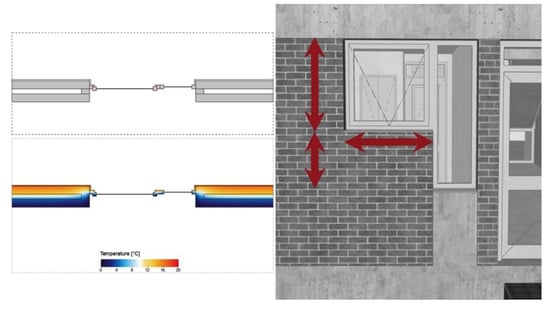
Figure 13.
Output of the calculation of the thermal bridge of the window inside a fictitious wall (left) and dimensions considered for the length to be attributed to the thermal bridge (right).
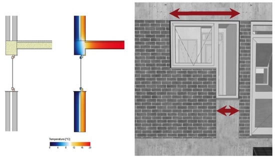
Figure 14.
Output of the calculation of the thermal bridge of the window in contact with the concrete (left) and dimensions considered for the length to be attributed to the thermal bridge (right).
In this calculation, the floor in contact with the beam was also included because it gave rise to another thermal bridge. By calculating the thermal bridge of the concrete beam in contact with the floor, the lengths already taken into consideration for the frames were excluded. Once all thermal bridges were calculated, they were attributed to each thermal block via the structures table. Alternatively, it is also possible to enter a table value of the thermal bridge, but the specific calculation for each element is always to be preferred. In this last sheet, the characteristics of the frame are specified. They can be selected from a vast library inside the plug-in, divided into glass type and frame material. The alternatives made available by the library are numerous and can satisfy even the cases of fixtures with particular performances. However, if the characteristics to be entered do not correspond to those present in the library, it is always possible to manually overwrite them for each frame or groups of frames. It is also necessary to start the calculation of the solar analysis (Figure 15) for all external frames (all internal doors will be automatically excluded). This operation has a double advantage. The first is that the data obtained can be used by the program in the calculation phase, while the second is that the professional receives support, during the design, from the interactive graph produced as a result of the calculation. This graph offers the possibility to investigate, day-by-day, hour-by-hour, the irradiation conditions of a given frame. So, it is possible to instantly evaluate the effectiveness of the positioning, dimensions, or shielding system adopted (Figure 16).
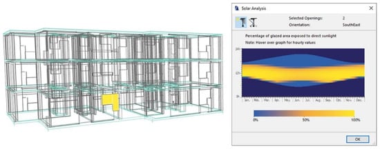
Figure 15.
Three-dimensional display of the selected window element and relative solar analysis.
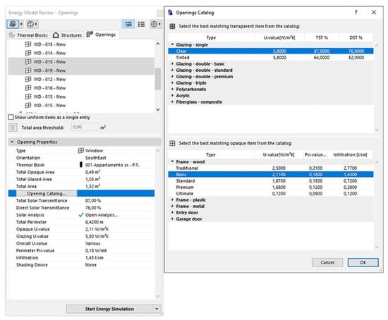
Figure 16.
Window for selecting openings/frames on the left, library of the glass type and frame material on the right.
Before proceeding with the energy simulation of the building, it is possible to select a “Reference building” in the calculation phase. This building is another virtual model that serves as a benchmark. Thanks to it, the advantages and disadvantages of the two alternatives of the same project can be immediately highlighted. Moreover, it is possible to compare the building under consideration with a similar one whose performance we already know. This is a completely optional operation. The simulation can very well proceed with the building data without any reference building.
However, in this case, it was decided to build a reference building model both for completeness in the study of the possibilities of this software, and to highlight considerations on the design applications extensively presented in the next paragraph. The construction of the reference building was based on the same geometric-architectural model of the case study building. The elements and climatic data used are completely identical; while thermo-physical properties of the elements are different.
In particular, the calibration of the building envelope was based on the guidelines dictated by the “Interministerial Decree of 26 June 2015—A” and by the “Interministerial Decree of 26 June 2015—B” [46]. The procedure adopted is purely for study purposes, as the building was not designed in Italy nor is it subject to Italian regulations. The parameters are classified in the standard according to the climatic zones of the locality. Italy is divided into 6 climatic zones ranging from zone A to zone F [47]. They differ in the value of degree days (GG). The “degree-day” is defined as the sum, over one year, of the (positive) difference between the internal ambient temperature and the average daily external temperature [48]. The indoor temperature in Italy has been set at 20 °C, so the degree days are calculated based on this temperature. It is evident that the Stirling building cannot be placed in the Italian climatic zones, therefore the problem arises of which climatic zone to choose to obtain the parameters of the reference building. It was decided to calculate the degree days near London (Ham Common, Richmond, BC, USA). In doing so, also the fictitious climatic zone according to Italian parameters was found. Although in England the degree days (HDD and CDD, respectively, Heating Degree Day and Cooling Degree Day) are used, they are calculated differently than the Italian ones, and in particular, they refer to an internal temperature of 15.5 °C instead of 20 °C. Comparing the GG calculated with two different temperatures is an operation that distorts the results at the start, it was necessary to calculate them through an online application [49]. It was used to choose the internal temperature to be included in the calculation. The output of this process is a spreadsheet in which the following are entered: The period of time considered and temperature of the reference indoor environments, source, accuracy of the climatic data for that area, weather station used, a table with monthly degree day values, and finally the total. A value of 3063 GG was considered. It was compared with the parameter suggested by the Italian standard. So, the Stirling building was ideally placed in the “climate zone F”. It indicates the period of heating system operation and it allows identifying the parameters that the building envelope must have to be considered as a reference building. EcoDesigner STAR can overwrite the new parameters on the old, as a finished element, to quickly update the Building Energy Model in a few steps. This avoids replacing the elements built previously (walls, floors, windows, etc.) and having to model the building again. The resulting building is better performing than the real building. It is because the building envelope is made up of elements with high thermal efficiency. After starting the energy simulation calculation, it is possible to save the building as a reference building. Finally, it can be used as a term of comparison when analyzing the building with real parameters.
6.2. Simulation Results
All the aspects studied and exposed were useful for the correct construction of the BEM model and a valid setting of the data for energy simulation. The previously built reference building was included in the appropriate tool section. At the end of the calculation, a final report was obtained.
The first section reports all the general data of the entire building, including geometric ones, and some average values for all the thermal zones. The data concerning the energy supplied to the building (heating system, lighting systems, internal heat inputs due to the presence of people, etc.) are shown in the form of a weekly chart. It provides an immediate understanding of which system requires the most energy. Therefore, it predicts which of these fields can be the most expensive in economic terms. The first section contributes to giving an overall view of the analyzed construction. The second section contains the same information as the first, but this time concerning the individual thermal blocks. Each block is associated with a weekly graph of the energy supplied and a graph on the energy emitted. In the specific case of the Stirling building, the 6 apartments are shown (each definitive with a thermal block) and a single common area (represented with a single thermal block). It was noted that the apartments that require less energy in a year are those on the first floor. It is because they exchange heat with the external environment only on three sides. On the fourth side, the apartments border an unheated internal environment. Both at floor and ceiling level they border with other heated rooms. Therefore, the heat losses are less. The accommodations that require more energy to maintain an optimal internal temperature are those on the top floor. Indeed, they exchange heat with the external environment even from the ceiling. Moreover, the roof slab, compared to the floor slabs, has a lower thickness and there is not any type of insulating layer. The apartments on the ground floor, on the other hand, have energy consumption closer to those on the first floor. Another aspect that can be immediately noticed is that the apartments on the right of the entrance (and therefore facing north) have slightly higher energy consumption than those facing south. The third section relates to the daily temperature profiles. It is possible to insert graphs for each day of the year of any thermal block, to show the curves of internal and external temperatures. During the design phase, these graphs are very useful to better calibrate the systems and know when it is necessary to heat or cool the rooms. The fourth section is dedicated to the energy consumption, environmental impact, and energy production (if renewable energy sources are present). Energy consumption is shown both as a table and as a graph, and is divided into categories (heating, cooling, domestic hot water production, consumption due to mechanical ventilation if present, lighting, and equipment). If the prices of the various energy sources are also set, the cost of the various systems can be known. The environmental impact is instead calculated through the kg/y of CO2 emitted, or the carbon dioxide expressed in kg emitted in a year.
The last section focuses on comparing the consumption of the building to be analyzed and a reference building. It is possible, through this section, to compare two variants of the same project, in order to know both the consumption of the two buildings. They are compared in economic terms.
In Table 2, the results of the simulation were reported.
Table 2.
Geometric characteristic of the analyzed apartment and simulation result ante and post ideal retrofit action.
The proposed interventions are to be considered the hypothesis that complete and conclude the entire process outlined above. It has to be remembered that the aim of this paper is not the design of improvement solutions for the James Stirling building, but the definition of a methodology that integrates the simulation energy in the BIM environment, thus identifying a valid design support tool. Anyway, some possible interventions aimed at reducing the consumption of individual apartments and improving the performance of the entire building are listed below:
- Addition of an insulating layer in the roof slab; the second and last level are those affected by greater heat losses; this occurs at the roof level, as can be seen from the thermography; thus acting on the attic, inserting an insulating layer that does not alter the aesthetic and structural components of the building, the consumption and costs for heating these apartments would be reduced;
- of the ground floor slab in contact with the ground; the consumption of the ground floor apartment, compared with the consumption of the apartment on the first level, is higher; it is hypothesized that improving the contact between the ground and the attic through the insertion of a crawl space, consumption can be reduced and made similar to that of the apartment on the first level;
- strengthening of the insulation package of the external cavity walls; currently the walls have an air gap and by blowing in insulating material their thermal transmittance values could be improved, thus reducing heat loss;
- replacement of fixtures; for this intervention two solutions could be opted for: (i) The first involves the complete replacement of the current fixtures with fixtures, similar in materials, but with double glass and thermal break; (ii) the second, if the first cannot be carried out due to the protected nature of the building, provides for the maintenance of the current wooden frames and for the replacement of the single glass with a double glass, capable of guaranteeing an improvement in the performance of the fixture.
By updating the BIM model with the new parameters, the BEM model will also be updated automatically. So, the energy simulation calculation can be quickly started.
The consumption of the apartment at the ground floor after the application of the retrofit actions is 12,243.32 kWh; while before the ideal retrofit actions was 16,349.43 kWh.
The apartment on the first floor adjoins two heated rooms, both at floor and ceiling level, with an annual consumption of 14,766.44 kWh, before the ideal retrofit actions, and of 11,741.08 kWh, after the ideal retrofit actions.
The consumption of this apartment is slightly lower than the ground floor apartment and significantly lowers. The apartment on the second level borders on a heated room at floor level and with the external environment at ceiling level. The annual consumption calculated was 22,539.95 kWh before the ideal retrofit actions, and 13,873.37 kWh after the ideal retrofit actions. Furthermore, it is possible to obtain the perspective sections of the apartments in which it is also possible to read the distribution of temperatures within the building envelope; this type of paper, following a correct interpretation, is particularly useful for identifying the areas of intervention.
Looking at the thermography of the new configuration of the building, it can be seen how the roof slab disperses less heat than the real configuration and how the windows and cavity walls break down the heat flow.
7. Results
In the previous section, the results of the process were reported. By conducting this study, it was possible to highlight the advantages and limitations of the tool EcoDesigner STAR application and to outline a clear picture of the potential and criticality of the chosen. The greatest advantage that is obtained from the use of ArchiCAD associated with EcoDesigner STAR is the overcoming of one of the major problems in this field, namely the transition from BIM to BEM. The modelling software allows the construction of a BIM model according to certified tools. Plug-in allows its interpretation in BEM with an almost instantaneous operation.
It is clear that this transition from BIM to BEM is error-free. Moreover, it is configured as an immediate operation when the designer builds the BIM to then conduct an energy analysis. Indeed, during the design and modelling process, it is necessary to better calibrate the data entered in the BIM, the used elements and the relationships established with other elements. It is also useful to facilitate the subsequent transformation of the Building Information Model Building Energy Model. It has to be reminded that, according to the BIM goals, the interoperability must take place from the earliest stages of design. To do this, all the professional figures required should be involved to operate with the same objectives and making the work faster and more effective.
If the BIM model is built to transform it into BEM, the operation is easy. In this way, it is possible to apply an energy simulation in all the design phases of a building. Clearly, this action occurs with degrees of detail and accuracy based on the progress of the project. So, better integration between design and energy analysis can be achieved. This latter is not relegating to the final phases of the project. As for typical energy analysis, at the end of the simulation process, many data can be obtained (both directly and indirectly). From them, it is possible to consider possible interventions aimed at reducing the consumption of apartments.
Another advantage of this tool is the feasibility to compare two or more variants of one of the same building. They can be compared both in the early stages of the project and in the final stages, managing to choose the best solution according to needs.
The output data looks user-friendly. It is an important aspect for the designer, who can know the advantages and disadvantages of a design choice almost immediately. For example, it is possible to choose the orientation and materials of the building envelope and start an initial energy simulation by mentioning the other fundamental data. Furthermore, it is possible to propose a different orientation and different types of materials for the building envelope, keeping the other data completely identical to the previous variant. Finally, it proceeds with the simulation of a second alternative and automatically compares it with the first, in order to obtain graphs on the savings and consumption of both and choose the most suitable solution. In order to support this consideration and to check the possible improvements of the tool, further comparison with a stand-alone software was performed. The main results are reported in Table 3. Regarding the building systems, “basic” means that there are just a few options to set the plants; “detailed” means that it is possible to set all the parameters.
Table 3.
Comparison with Termolog software.
8. Discussion
The main goals of this study are the analysis of the interaction between BIM and energy simulation, through a review of the main existing commercial tools, and the identification and application of a methodology in a BIM environment by using Graphisoft’s BIM software Archicad and the plug-in for dynamic energy simulation EcoDesigner STAR. The application on a case study gave the possibility to explore advantages and limits of this commercial tools and, consequently, to provide some possible improvements.
As said in Section 4, the selection of the analyzed tool was based on some main criteria. The first characteristics are the versatility and the possibility to combine BIM modelling with well-integrated plug-in for energy analysis, to import and export building 2D drawings, BIM modelling and 3D visualization, quasi-static energy diagnosis, dynamic energy diagnosis, calculation of thermal bridges, and calculation of renewable energy sources. The second characteristic is that it meets the requirements set by the most advanced energy diagnosis standards, such as UNI EN ISO 52016-1 for the calculation in dynamic hourly regime, and ASHRAE 140-2017 and UNI/TS 11300 on the monthly average stationary calculation. Finally, it meets the validity requirements required by buildingSMART for IFC certification. All these requirements, according to the conducted study and the results reported above, were confirmed.
Although the results of this study are satisfactory, some critical issues and disadvantages were found within the application and possible fields. They can be addressed in future research, in order to improve digital tools and achieve perfect integration between BIM and BEM, without the passage of digital models in third-party analysis software. As shown in Table 3, the major limitation that has been detected is the poor personalization of data relating to heating systems. The type of data that can be set is limited and inherent to the fundamental characteristics of the system, such as the nominal power, the thermoregulation, the nominal capacity, and the COP/EER. It is not possible to specify the efficiency and to insert the heating terminals with their technical specifications. Furthermore, it is not possible to set the vapor diffusion resistance factor of the material, the efficiency and the emission of the system.
Thus, as improvements of the tools there is the implementation of the possibility to set these latter parameters. In particular, giving the possibility to set the vapor diffusion resistance factor of the materials, it will improve the calculation of possible surface and interstitial condensation. Regarding the HVAC system, in order to provide a more precise energy analysis, the tool could be improved by giving the possibility to set the efficiency of the boiler and the emission system characteristics and typology. Furthermore, it could be necessary to detail the parameters to be inserted regarding the nominal capacity, the thermoregulation and the COP/EER. Finally, some details about the lighting system and mainly the control system should be added.
9. Conclusions
The purpose of the paper is to study a new integrated energy simulation methodology in a BIM environment by using Graphisoft’s BIM software Archicad and the plug-in for dynamic energy simulation EcoDesigner STAR. They have been selected after a careful study of the rules on energy analysis, an examination of the operational potential of different software on the market, and research conducted by a wide scientific community interested in various capacities in issues related to the interaction between architecture and energy analysis. Thanks to the application on the case study, the advantages and disadvantages of the existing tools were highlighted and compared. The greatest advantage that is obtained from the use of ArchiCAD associated with EcoDesigner STAR is the overcoming of one of the major problems in this field, namely the transition from BIM to BEM. The modelling software allows the construction of a BIM model according to certified tools. Plug-in allows its interpretation in BEM with an almost instantaneous operation when the designer builds the BIM with the intention of conducting an energy analysis. Another advantage of this tool is the feasibility to compare two or more variants of one of the same building, both in the early stages of the project and in the final stages, managing to choose the best solution according to needs. Furthermore, the output data looks user-friendly. It is an important aspect for the designer, who can know the advantages and disadvantages of a design choice almost immediately. Moreover, some critical issues and disadvantages were found within the application and possible fields. The major limitation that has been detected is the poor personalization of data relating to heating systems. The type of data that can be set is limited and inherent to the fundamental characteristics of the system, such as the nominal power, the thermoregulation, the nominal capacity, and the COP/EER. It is not possible to specify the efficiency and to insert the heating terminals with their technical specifications. Furthermore, it is not possible to set the vapor diffusion resistance factor of the material, the efficiency, and the emission of the system.
These lacks can be used as a starting point for further improvements to the tool. The possibility to set the vapor diffusion resistance factor of the materials would improve the calculation of possible surface and interstitial condensation. Regarding a more precise analysis, the tool could be improved by giving the possibility to set the efficiency of the boiler and the emission system characteristics and typology and to detail the parameters to be inserted regarding the nominal capacity, the thermoregulation, and the COP/EER. Finally, some details about the lighting system and mainly the control system should be added.
Author Contributions
Conceptualization, M.B., S.D.L. and G.L.; methodology, M.B., S.D.L. and G.L.; software, S.D.L.; validation, M.B., S.D.L. and G.L.; formal analysis, M.B., S.D.L. and G.L.; investigation, M.B., S.D.L. and G.L.; data curation, S.D.L.; writing—original draft preparation, M.B., S.D.L. and G.L.; writing—review and editing, M.B., S.D.L. and G.L.; visualization, M.B., S.D.L. and G.L.; supervision, M.B. All authors have read and agreed to the published version of the manuscript.
Funding
This research received no external funding.
Institutional Review Board Statement
Not applicable.
Informed Consent Statement
Not applicable.
Data Availability Statement
The data presented in this study are available on request from the corresponding author.
Acknowledgments
This study starts from the degree thesis [50], carried out by Simone Di Lisi with the fundamental support of Arch. Fabrizio Agnello and of the Ing. Marco Beccali.
Conflicts of Interest
The authors declare no conflict of interest.
References
- Wong, J.H.; Rashidi, A.; Arashpour, M. Evaluating the Impact of Building Information Modeling on the Labor Productivity of Construction Projects in Malaysia. Buildings 2020, 10, 66. [Google Scholar] [CrossRef]
- Tu, K.J.; Vernatha, D. Application of Building Information Modeling in energy management of individual departments occupying university facilities. Int. J. Archit. Environ. Eng. 2016, 10, 225–231. [Google Scholar]
- Alahmad, M.; Nader, W.; Neal, J.; Shi, J.; Berryman, C.; Cho, Y.; Lau, S.-K.; Li, H.; Schwer, A.; Shen, Z.; et al. Real Time Power Monitoring & integration with BIM. In Proceedings of the IECON 2010—36th Annual Conference on IEEE Industrial Electronics Society, Glendale, AZ, USA, 7–10 November 2010; pp. 2454–2458. [Google Scholar]
- Woo, J.H.; Diggelman, C.; Abushakra, B. BIM-based energy monitoring with XML parsing engine. In Proceedings of the 28th ISARC, Seoul, Korea, 29 June–2 July 2011; pp. 544–545. [Google Scholar]
- Maltese, S.; Tagliabue, L.C.; Cecconi, F.R.; Pasini, D.; Manfren, M.; Ciribini, A.L.C. Sustainability Assessment through Green BIM for Environmental, Social and Economic Efficiency. Procedia Eng. 2017, 180, 520–530. [Google Scholar] [CrossRef]
- Shin, M.; Haberl, J.S. Thermal zoning for building HVAC design and energy simulation: A literature review. Energy Build. 2019, 203, 109429. [Google Scholar] [CrossRef]
- Waibel, C.; Evins, R.; Carmeliet, J. Co-simulation and optimization of building geometry and multi-energy systems: Interdependencies in energy supply, energy demand and solar potentials. Appl. Energy 2019, 242, 1661–1682. [Google Scholar] [CrossRef]
- Liu, S.; Ning, X. A Two-Stage Building Information Modeling Based Building Design Method to Improve Lighting Environment and Increase Energy Efficiency. Appl. Sci. 2019, 9, 4076. [Google Scholar] [CrossRef]
- Jeong, W.; Yan, W.; Lee, C.J. Thermal Performance Visualization Using Object−Oriented Physical and Building Information Modeling. Appl. Sci. 2020, 10, 5888. [Google Scholar] [CrossRef]
- Clarke, J.; Hensen, J. Integrated building performance simulation: Progress, prospects and requirements. Build. Environ. 2015, 91, 294–306. [Google Scholar] [CrossRef]
- Ramaji, E.; Memari, A.M. Review of BIM’s application in energy simulation: Tools, issues, and solutions. Autom. Constr. 2019, 97, 164–180. [Google Scholar]
- Andriamamonjy, A.; Saelens, D.; Klein, R. A combined scientometric and conventional literature review to grasp the entire BIM knowledge and its integration with energy simulation. J. Build. Eng. 2019, 22, 513–527. [Google Scholar] [CrossRef]
- Bracht, M.; Melo, A.; Lamberts, R. A metamodel for building information modeling-building energy modeling integration in early design stage. Autom. Constr. 2021, 121, 103422. [Google Scholar] [CrossRef]
- Kamel, E.; Memari, A.M. Automated Building Energy Modeling and Assessment Tool (ABEMAT). Energy 2018, 147, 15–24. [Google Scholar] [CrossRef]
- Kim, J.B.; Jeong, W.; Clayton, M.J.; Haberl, J.S.; Yan, W. Developing a physical BIM library for building thermal energy simulation. Autom. Constr. 2015, 50, 16–28. [Google Scholar] [CrossRef]
- El Sayary, S.; Omar, O. Designing a BIM energy-consumption template to calculate and achieve a net-zero-energy house. Sol. Energy 2021, 216, 315–320. [Google Scholar] [CrossRef]
- Xu, X.; Mumford, T.; Zou, P.X. Life-cycle building information modelling (BIM) engaged framework for improving building energy performance. Energy Build. 2021, 231, 110496. [Google Scholar] [CrossRef]
- Utkucu, D.; Sözer, H. Interoperability and data exchange within BIM platform to evaluate building energy performance and indoor comfort. Autom. Constr. 2020, 116, 103225. [Google Scholar] [CrossRef]
- Rodrigues, F.; Isayeva, A.; Rodrigues, H.; Pinto, A. Energy efficiency assessment of a public building resourcing a BIM model. Innov. Infrastruct. Solut. 2020, 5. [Google Scholar] [CrossRef]
- Tushar, Q.; Bhuiyan, M.A.; Zhang, G.; Maqsood, T. An integrated approach of BIM-enabled LCA and energy simulation: The optimized solution towards sustainable development. J. Clean. Prod. 2021, 289, 125622. [Google Scholar] [CrossRef]
- Alam, J.; Ham, J.J. Towards a BIM-based energy rating system. In Proceedings of the 19th International Conference on Computer-Aided Architectural Design Research in Asia: Rethinking Comprehensive Design: Speculative Counterculture, Kyoto, Japan, 14–16 May 2014; pp. 285–294. [Google Scholar]
- Jalaei, F.; Jrade, A. Integrating BIM with Green Building Certification System, Energy Analysis, and Cost Estimating Tools to Conceptually Design Sustainable Buildings. In Proceedings of the Construction Research Congress 2014, Atlanta, GA, USA, 19–21 May 2014; American Society of Civil Engineers (ASCE): Reston, VA, USA, 2014; pp. 140–149. [Google Scholar]
- IESVE. Available online: https://www.iesve.com/software/BIM (accessed on 10 January 2021).
- ENERGY PLUS. Available online: https://energyplus.net/ (accessed on 10 January 2021).
- Hirsch, J.J.; Lawrence Berkeley National Laboratory. eQUEST. Available online: http://www.doe2.com/eQuest/ (accessed on 12 January 2013).
- Gao, H.; Koch, C.; Wu, Y. Building information modelling based building energy modelling: A review. Appl. Energy 2019, 238, 320–343. [Google Scholar] [CrossRef]
- Autodesk. Available online: https://www.autodesk.com/products/revit/architecture (accessed on 10 January 2021).
- Graphisoft. Available online: https://graphisoft.com/ (accessed on 10 January 2021).
- Allplan. Available online: https://www.allplan.com/us_en/ (accessed on 10 January 2021).
- Muñoz, J.N.; Manzanares, F.V.; Gonçalves, M.M. BIM Approach to Modeling a Sports Pavilion for University Use. Appl. Sci. 2020, 10, 8895. [Google Scholar] [CrossRef]
- Available online: https://www.acca.it/bim-modeling-software?gclid=CjwKCAiAxeX_BRASEiwAc1Qdkb_-Th144lYXAi8UFc8tsWEIJt745zXabINlVxZUYBia5CbHvS0zIBoCCYkQAvD_BwE (accessed on 3 March 2021).
- ASHRAE 140-2017. Available online: https://xp20.ashrae.org/140-2017/ (accessed on 3 March 2021).
- Decreto Legislativo 29 Dicembre 2006, n. 311 “Disposizioni Correttive ed Integrative al Decreto Legislativo 19 Agosto 2005, n. 192, Recante Attuazione della Direttiva 2002/91/CE, Relativa al Rendimento Energetico Nell’edilizia”. Available online: https://www.camera.it/parlam/leggi/deleghe/testi/06311dl.htm (accessed on 3 March 2021).
- Decreto Legislativo 30 Maggio 2008, n. 115 “Attuazione della direttiva 2006/32/CE Relativa All’efficienza Degli Usi Finali Dell’energia e i Servizi Energetici e Abrogazione Della Direttiva 93/76/CEE”. Available online: https://www.camera.it/parlam/leggi/deleghe/08115dl.htm (accessed on 3 March 2021).
- UNI/TS 11300-1:2014, Prestazioni Energetiche Degli Edifici—Parte 1: Determinazione del Fabbisogno di Energia Termica Dell’edificio per la Climatizzazione Estiva ed Invernale. Available online: http://store.uni.com/catalogo/uni-ts-11300-1-2014 (accessed on 3 March 2021).
- UNI/TS 11300-2:2019, Prestazioni Energetiche Degli Edifici—Parte 2: Determinazione del Fabbisogno di Energia Primaria e dei Rendimenti per la Climatizzazione Invernale, per la Produzione di Acqua Calda Sanitaria, per la Ventilazione e per L’illuminazione in Edifici non Residenziali. Available online: http://store.uni.com/catalogo/uni-ts-11300-2-2014 (accessed on 3 March 2021).
- Design Builder. Available online: https://designbuilder.co.uk// (accessed on 10 January 2021).
- Open Studio. Available online: https://www.openstudio.net/ (accessed on 10 January 2021).
- Simergy. Available online: https://d-alchemy.com/products/simergy (accessed on 10 January 2021).
- Logicalsoft. Available online: https://www.logical.it/software-per-la-termotecnica (accessed on 10 January 2021).
- UNI EN ISO 52016-1:2018, Prestazione Energetica Degli Edifici—Fabbisogni Energetici per Riscaldamento e Raffrescamento, Temperature Interne e Carichi Termici Sensibili e Latenti—Parte 1: Procedure di Calcolo. Available online: http://store.uni.com/catalogo/uni-en-iso-52016-1-2018 (accessed on 3 March 2021).
- EcodesignStar. Available online: https://www.bimtechla.com/pdf/Brochure-EcoDesigner_STAR_Brochure.pdf (accessed on 3 March 2021).
- Mazzarella, L. Dati climatici G. De Giorgio. In Giornata Di Studio Giovanni De Giorgio; Politecnico di Milano: Milano, Italy, 18 November 1997. [Google Scholar]
- Stirling, J.; Gowan, J. Flats at Langham House, Ham Common, Richmond. In Architectural Design; 1958; Available online: https://historicengland.org.uk/listing/the-list/list-entry/1051027 (accessed on 3 March 2021).
- Izzo, A.; Gubitosi, C. James Stirling, Officina Edizioni, Roma. 1976. [Google Scholar]
- Decreto Interministeriale 26 Giugno 2015—Applicazione Delle Metodologie di Calcolo Delle Prestazioni Energetiche e Definizione Delle Prescrizioni e dei Requisiti Minimi Degli Edifici. Available online: https://www.gazzettaufficiale.it/eli/id/2015/07/15/15A05198/sg (accessed on 3 March 2021).
- D.P.R. 26 August 1993, n. 412 (Annex A), on the subject of the “Regulation containing rules for the design, installation, operation and maintenance of the thermal systems of buildings for the purpose of containing energy consumption”.
- UNI EN ISO 15927-6: 2008, in Terms of Performance Hygrometric Temperature of Buildings—Calculation and Presentation of Climatic Data—Part 6: Cumulated Temperature Differences (Degree Days). Available online: https://standards.iteh.ai/catalog/standards/sist/3da76bd7-e17c-4e3c-a10e-4f0be76d017d/sist-en-iso-15927-6-2008 (accessed on 3 March 2021).
- Degreedays. Available online: https://www.degreedays.net/#generate (accessed on 10 January 2021).
- Di Lisi, S. Simulazione Energetica in Ambiente BIM Per Il Progetto di Architettura. Master’s Thesis, University of Palermo, Palermo, Italy, 2020. [Google Scholar]


Publisher’s Note: MDPI stays neutral with regard to jurisdictional claims in published maps and institutional affiliations. |
© 2021 by the authors. Licensee MDPI, Basel, Switzerland. This article is an open access article distributed under the terms and conditions of the Creative Commons Attribution (CC BY) license (http://creativecommons.org/licenses/by/4.0/).