Article

Multifunctional Hyperelastic Structured Surface for Tunable and Switchable Transparency

by
Rayehe Karimi Mahabadi
1,2,
Taha Goudarzi
3,
Romain Fleury
2,* and
Reza Naghdabadi
1,4,*
1
Department of Mechanical Engineering, Sharif University of Technology, Azadi Ave, 11365–11155 Tehran, Iran
2
Laboratory of Wave Engineering, Department of Electrical Engineering, École Polytechnique Fédérale de Lausanne (EPFL), Station 11, Route Cantonale, 1015 Lausanne, Switzerland
3
Department of Mechanical Engineering, Amirkabir University of Technology (Tehran Polytechnic), Hafez Ave, 15916–34311 Tehran, Iran
4
Institute for Nanoscience and Nanotechnology, Sharif University of Technology, Azadi Ave, 11365–11155 Tehran, Iran
*
Authors to whom correspondence should be addressed.
Appl. Sci. 2021, 11(5), 2255; https://doi.org/10.3390/app11052255
Submission received: 5 February 2021 / Revised: 26 February 2021 / Accepted: 28 February 2021 / Published: 4 March 2021
(This article belongs to the Section Electrical, Electronics and Communications Engineering)

Abstract

:
We leverage the crucial hyperelastic properties of a multifunctional structured surface to optimize the reconfigurability of the electromagnetic transmission under large nonlinear mechanical deformations. This multiphysics, multifunctional, hyperelastic structured surface (HSS) offers two simultaneous intriguing functionalities; tunability and switchability. It is made of copper resonators and a Polydimethylsiloxane (PDMS) substrate, which is one of the most favorable deformable substrates due to its hyperelastic behavior. The proposed HSS is fabricated via an original cost-effective technique and the multiphysics functionalities are captured in both experimental tests and numerical simulations. Leveraging the hyperelastic behavior, we demonstrate up to 8% percent shift in the resonance frequency in the GHz range, for average applied mechanical strains of around 17%. The hyperelastic deformations can continuously increase/decrease the magnitude of the scattering parameter S21 in the frequency range of 10.9 GHz to 11.8 GHz by more than 40 dB, changing from being largely transparent to opaque and vice versa. The potential of hyperelastic behavior to account for the multifunctionality of the HSS is validated experimentally.

1. Introduction

Metasurfaces or planar metamaterials are engineered surfaces that use the tailored polarization response of resonant meta-atoms to control incident electromagnetic waves over electrically small thicknesses [1]. Metasurfaces have numerous applications, including in antennas [2], superlenses [3], sensors [4], holograms [5,6], imaging devices [7,8,9], polarizers [10], high impedance surfaces [11], and structural color generation [12]. Passive metasurfaces, made of fixed resonant meta-atoms, are restricted to a single pre-determined fixed frequency response. Modifying a passive metasurface in such a way to enable external reconfiguration and tuning of its resonance frequency/bandwidth is a much sought functionality in many high-end applications, from reflect/transmit arrays to smart conformal telecommunication systems. Tunable metasurfaces can be achieved through several approaches such as geometric reconfiguration of the resonators mediated by mechanical deformations [13] or electronic components, like varactor diodes [14], PIN diodes [15], and micro-electro-mechanical systems (MEMS) switches [16]. In addition, one can change the electromagnetic properties of the substrate by using materials that respond strongly to an external electric or magnetic bias, such as liquid crystals [17], graphene [18], silicon [19], or ferrite [20]. Reconfigurability can further be increased by intelligent mechanical designs, such as origami-based structures [21]. Often, however, the required bias network detrimentally increases the mass and complexity of the design, making it impractical especially for applications requiring large surfaces [22,23]. In such cases, mechanical deformation is the best option as it allows reconfiguring the entire surface at once by acting only on its boundaries. Such design, however, requires careful modeling of the mechanical deformation, especially of the boundary effects and non-linear deformations that can occur when the deformations are large.
In this paper, we propose the use of hyperelastic substrates to create a multifunctional hyperelastic structured surface (HSS) with large electromagnetic reconfigurability. We employ copper resonators and a hyperelastic substrate made of Polydimethylsiloxane (PDMS), operating between 10 and 13 GHz. To find the resonator geometry that results in an optimal level of mechanical and electromagnetic reconfigurability without reaching the maximum allowed value of local stress, we follow an optimization procedure seeded by common resonator geometries [13,24,25,26] in order to find the optimal design in terms of resonance frequency shift (RFS). We fabricate the optimized HSS through a cost-effective method and measure its scattering parameter S21 under several mechanical deformations.

2. Materials and Methods

2.1. Analysis and Design

The behavior of an HSS is governed by its unit cell characteristics. Accordingly, we start by considering an ensemble of potential unit cell geometries commonly found in the literature [13,24,25,26], and shown in Figure 1a–f. Comparing the potential of these possible geometries in terms of mechanical reconfigurability requires us to solve the expected transmission coefficient of the metasurface when subject to different level of uniaxial deformations, and define a useful performance metric.
Let us first describe how we solve this complex coupled-physics situation. We numerically solve the Multiphysics (both mechanics and electromagnetics) problem by finding the mechanical equilibrium of the periodic system when subject to a given level of deformation along x, and then solve Maxwell’s equation to obtain the scattering response of the deformed surface when illuminated by a normally incident plane wave polarized along y. These two numerical steps both consider a single unit cell subject to periodic boundary conditions, and are implemented using the commercial Finite Element software, COMSOL Multiphysics [27]. We utilize three different physics: Electromagnetic Waves (Frequency Domain Solver), Structural Mechanics (Stationary Solver), and the Moving Mesh feature. In the electromagnetic analysis, Floquet periodic boundary conditions [28] are applied on the deformed opposite transverse surfaces. In the mechanical analysis, displacements of the opposite transverse surfaces are coupled to enforce periodic boundary conditions. Moreover, air layers on the top and the bottom of the unit cell are handled using the moving mesh feature, and discretized using an arbitrary Lagrangian-Eulerian mesh for easy adaptation to the deformed unit cell [29]. Compared to prior arts, our method fully takes into account the key effects of both nonlinear substrate deformation by considering neo-Hookean mechanical constitutive relations [30], as well as the effect of the microscopic deformation on the electromagnetic response.
Defining the same gap size and wire width for all the resonator geometries, we now focus on evaluating the effect of geometry on the deformation sensitivity of these HSSs, defining the following performance metric. We compared the resonance frequency shift (RFS), expressed as a percentage of the natural resonance frequency, for each unit cell under the same uniaxial deformation. Thus, we fixed the average unit cell strain to be 1 percent in the x-direction ( ε ¯ x x = 0.01 ). All the resonators are made of copper with relative permittivity 1, electrical conductivity 59.98 MS/m, Young’s modulus 110 GPa, and Poisson’s ratio 0.35. The substrate is made of PDMS with relative permittivity 2.8, electrical conductivity 0.025 pS/m, Young’s modulus 750 kPa, and Poisson’s ratio 0.49. The RFS values are shown below the various designs in the figure. It is seen that parallel bar resonators, Figure 1f, show more sensitivity to the applied deformation compared to the other geometries. The sensitivity of the parallel bar resonators to the number of bars, their width and length and the gap size between them necessitates an optimization in order to obtain the optimal resonator geometry.
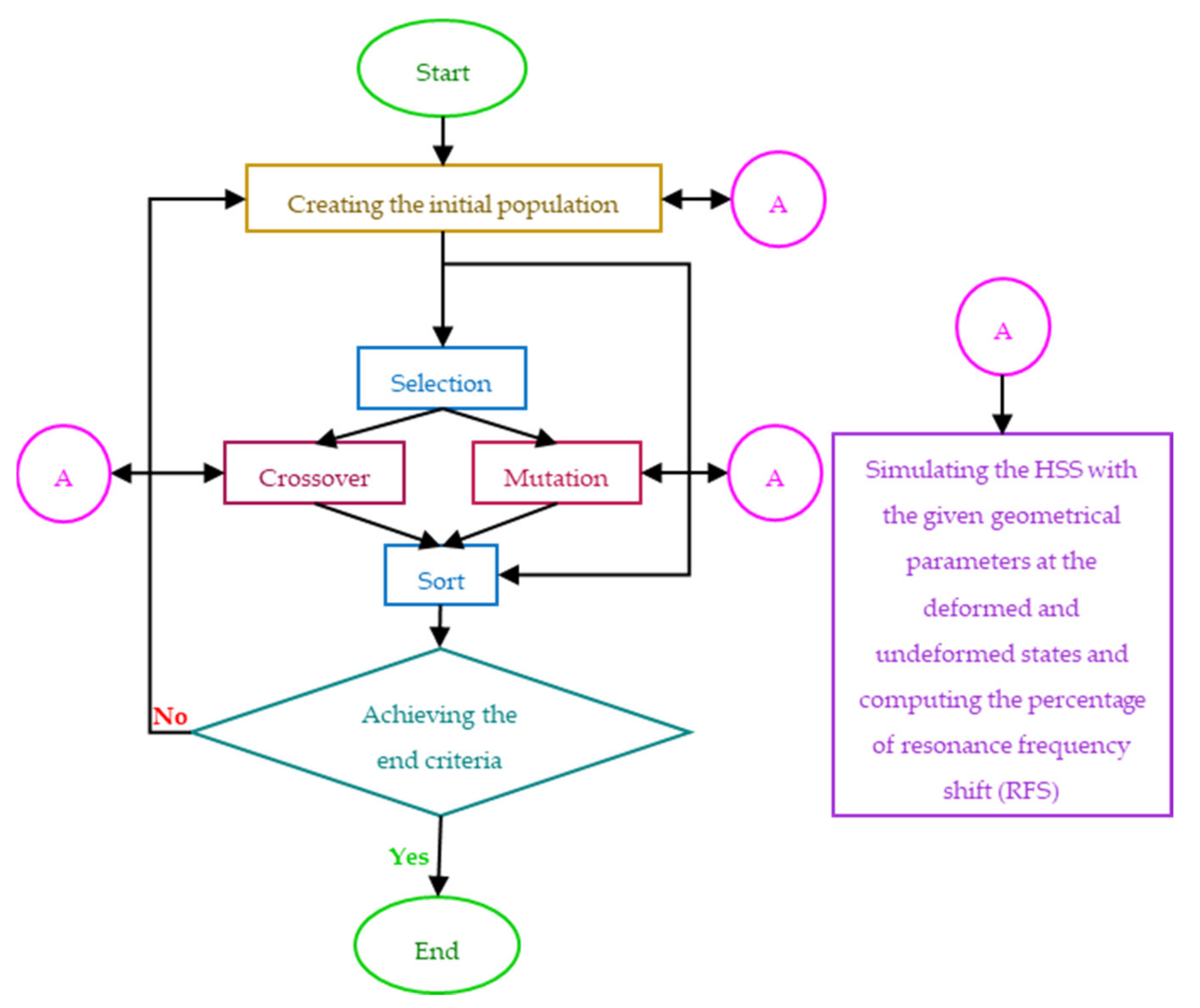
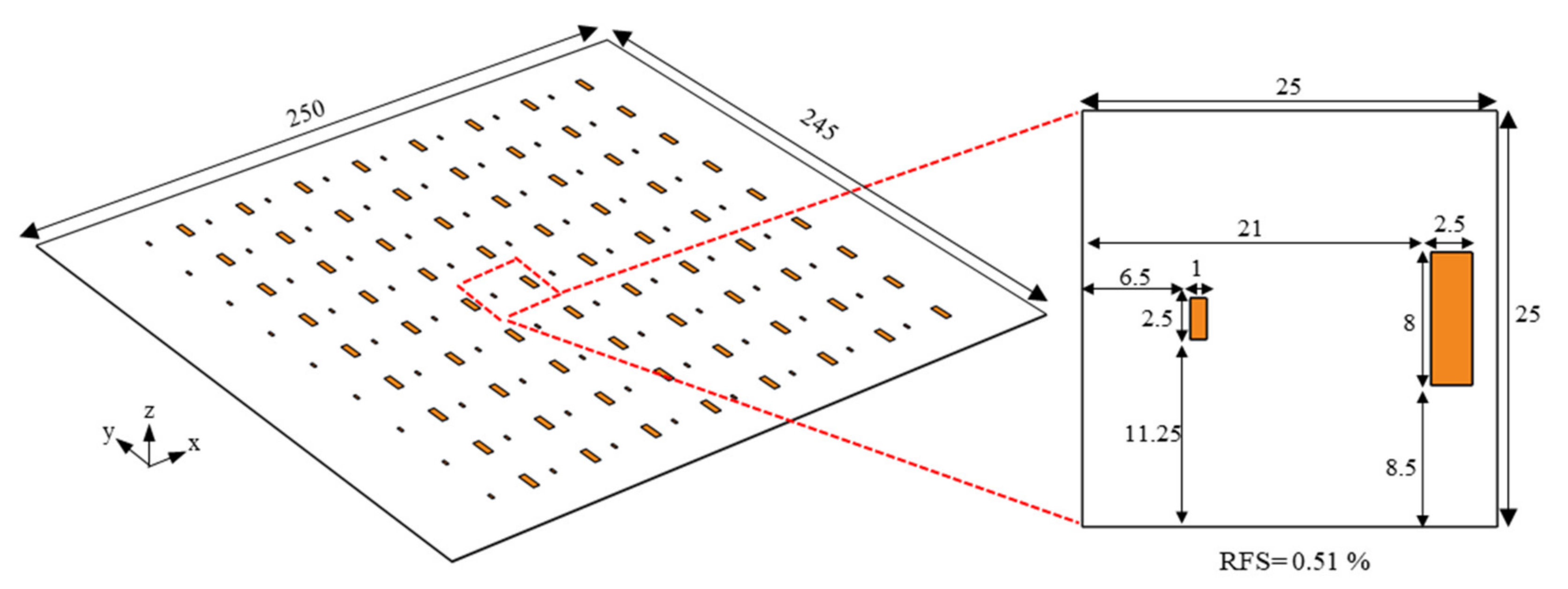
We implemented a genetic algorithm (GA) to find the optimum choice for the geometrical design parameters of the HSS. The flowchart of this optimization is presented in Figure 2. We consider the number of bars, their length and width, and the gap size between them as design variables that create a so-called chromosome, a potential solution for the optimization problem. Moreover, we take advantage of Crossover and Mutation operators to create new generations out of the existing chromosomes. Here, the former swaps the length between two randomly selected chromosomes and the latter reproduces the width and gap size of each randomly selected chromosome. The objective function of this algorithm calculates the RFS for a given applied mechanical deformation ( ε ¯ x x = 0.01 ). The output of this optimization is the resonator geometric parameters that generates the maximum RFS under the given mechanical deformation. We repeated the optimization several times to extend the surveyed models. The optimum resonator geometry, illustrated in Figure 3, is the outcome of the optimization survey on more than 1650 chromosomes that shows a RFS of 0.51% for an applied strain of 1% in the x-direction.
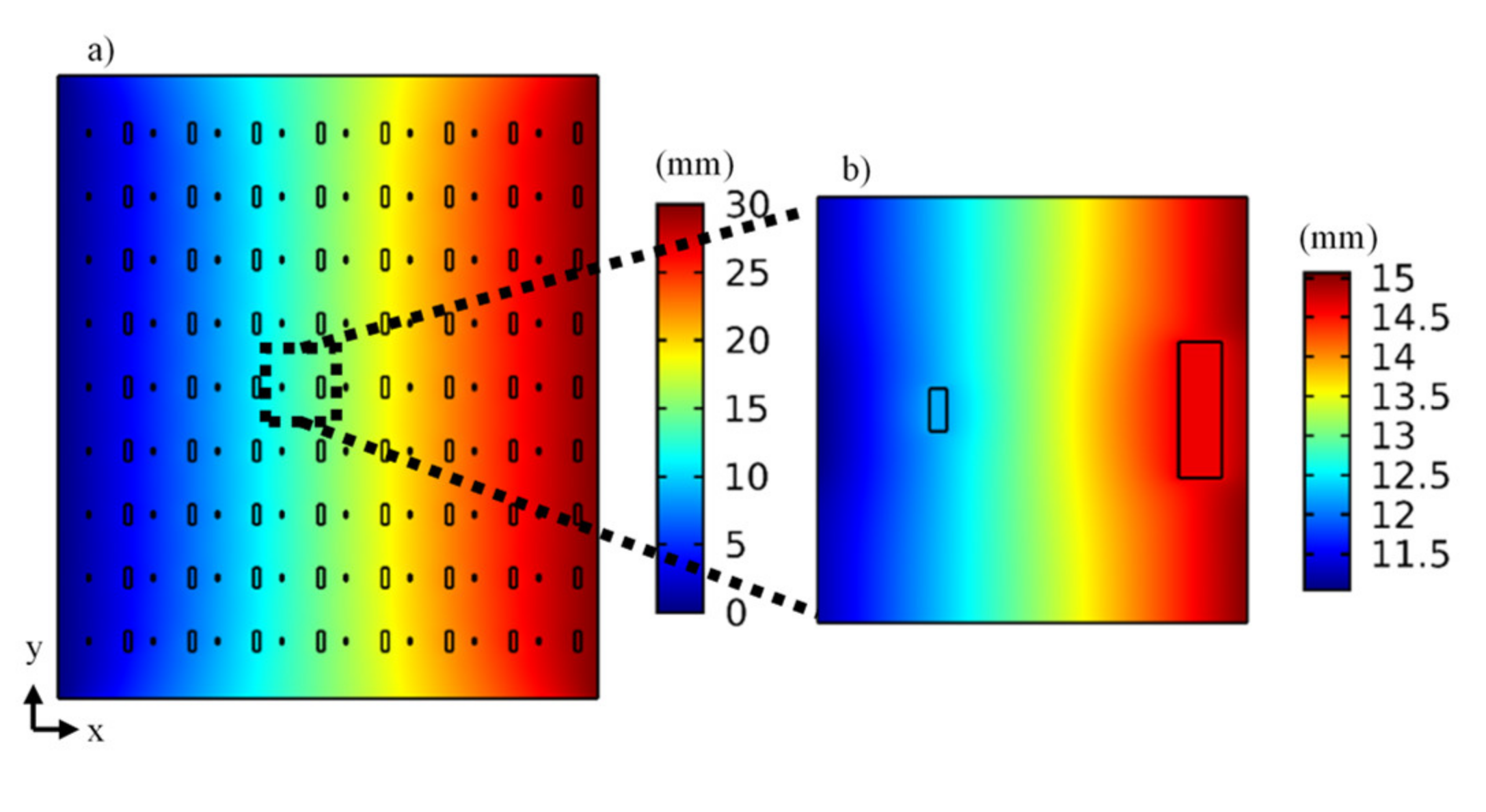
We continue the study by considering a finite system. It consists of an array of 8 × 9 unit cells positioned on a 250 × 245 × 0.25 mm PDMS film (see Figure 3). The deformation of the HSS at the boundaries of the system is not the same as that experienced far from the boundaries. Assuming that the metasurface is operated for beams centered in the bulk, it is enough to find the deformation experienced by middle cells by the periodic boundary conditions to estimate the variation of the electromagnetic transmission properties. To this end, we performed a mechanical simulation on the whole surface, and exported the deformation for one of the central unit cells for which we calculated the electromagnetic response subject to periodic boundary conditions. As an example, for an applied boundary displacement of 30 mm in the x-direction, the displacement field of the central unit cell is shown in Figure 4.

2.2. Experimental Section

2.2.1. Material

For the resonators, we use Curtonic foils (copper foils with a self-adhesive) from TechSoft company with a thickness of 0.025 mm. Moreover, we use PDMS films from SILEX Silicones Ltd. manufacturer with a thickness of 0.25 mm. These films are provided on a transparent supporting plastic sheet and can easily be cut to the desired size.

2.2.2. Fabrication Process

We used the following technique to fabricate a large area HSS, which is also more cost-effective than the prevalent processing techniques such as conventional lithography [31], shadow mask lithography [32], electron beam lithography [33], laser micro-lens array lithography [34], electroplating [35], and direct laser writing [36]. Using a vinyl cutter (Roland GS-24), we cut resonators out of the Curtonic foil, as shown in Figure 5a,b. Making use of transfer tape, we can move these resonators on the desired substrate. By means of the sticky backside of these copper patches, they can firmly adhere to different substrates, however, because of the hydrophobicity of the PDMS [37], the sticky backside of the copper does not adhere to it. Although treating the PDMS with plasma is a helpful way of activation that increases its adhesion potential [37], it creates a thin brittle oxidized layer on the PDMS surface, called “silica-like” layer. A silica-like layer has a higher elastic modulus and a lower resistance to rupture compared with the untreated PDMS. The optical properties of the PDMS such as transparency can also be impaired by this operation. The silica-like layer is brittle and no longer shows the hyperelastic behavior of the original PDMS film which in turn results in the formation of micro cracks [38,39].
In order to avoid the adverse effects of the surface activation, we try the plasma treatment using an oxygen plasma gun to restrict the activation process to the selected spots on the PDMS film, where resonators will be positioned (see Figure 5c). Since the PDMS film is provided on a transparent plastic sheet, we put the printed sheet of the resonators under the PDMS film to accurately determine of the resonators’ locations. It is noticed that PDMS has a porous structure and after a while, as a consequence of the change in its molecules conformation, the activated molecules do not stay on the surface for a long time and swap their places with the ones in the bulk. Thus, sticking the copper resonators should be done right after the activation; otherwise, reactivation is required. When the copper resonators are placed on the activated spots of the PDMS surface, the bonds generated between the activated PDMS and the backside adhesive of the resonators maintain the activated molecules in their positions. The fabricated HSS is shown in Figure 5d.

2.2.3. Measurements and Characterization

In order to experimentally study the electromagnetic behavior of this HSS, we used a custom-made setup shown in Figure 6. To apply the deformation, we designed a stretching apparatus. We attached Polymethylmeth-acrylate (PMMA) plates, which have good affinity with PDMS films, to the motion controller (Thorlabs XR25C/M) and the bracket (Thorlabs VB01B/M) to make movable and fixed grippers, respectively. We fixed 40 mm of the HSS on the PMMA plate using cloth tapes (tesa 4651) to assure a complete fixation and application of a uniform pressure to the boundaries of the HSS. Using the installed micrometer on the motion controller, the distance change between the grippers could be precisely controlled with an accuracy of 0.01 mm. Moreover, we numerically checked the generated reaction forces on the grippers to be less than the maximum limit supported by the motion controller. We applied grease, a semisolid lubricant, underneath the moving gripper to create a more uniform motion. To easily transfer the HSS to the setup without applying an excess deformation during the mounting process, we did not remove the supporting plastic sheet underneath the PDMS film until the very end of the mounting process.
To send and receive the electromagnetic waves, we used a standard gain horn antenna (Narda corporation, model 640, 8.2 GHz–12.4 GHz) and a monopole antenna (19 mm wire fixed on a probe), respectively. The horn antenna was placed in front of the surface in a distance of 650 mm from the front side of the HSS. The monopole antenna was placed on the other side of the HSS in line with the horn antenna with a distance of 60 mm from the backside of the HSS. The whole mechanical setup, as well as the monopole antenna was placed in a compact anechoic enclosure with pyramidal absorbers to minimize the reflections from surroundings and to avoid interference from the environment. Taking advantage of the embedded micrometer on the motion controller, the displacement was precisely applied to the movable gripper and the scattering parameter S21 was measured at each step using a vector network analyzer (VNA Rohde & Schwarz ZNB 20. 100 kHz–20 GHz).

3. Results and Discussion

To reveal the tunability of the proposed design, we numerically computed and experimentally measured the scattering parameter S21 of the proposed HSS under various mechanical deformations. We computed the scattering parameter S21 of the HSS for the gradual increase in the mechanical displacement in steps of 5 mm up to 30 mm. The resonance frequency of the HSS in the deformed state ( f 0 ), the RFS, percentage of the RFS with respect to the undeformed resonance frequency ( RFS f 0 Undeformed × 100 ) are presented in Table 1. In addition, the change in the scattering parameter of the HSS at the undeformed ( Δ S 21 @ f 0 Undeformed ) and deformed resonance frequency ( Δ S 21 @ f 0 ) for the applied displacements to the HSS ( U x ) in accordance with the generated xx component of the average strain in the unit cell ( ε ¯ x x ) are presented in Table 1.
Before the experimental measurements, to reduce the Mullin’s effect of the PDMS in the experimental results, we applied several loading/unloading cycles to the fabricated HSS. Then, we gradually increased the displacement and measured the resonance frequency of the fabricated HSS. The procedure has been repeated three times and the three datasets are distinguished by Roman numbers as a subscript of the applied displacement in Figure 7, showing excellent repeatability and agreement with numerical predictions. The existing limit in the transmissibility of the moving gripper impeded increasing the deformation above 15 mm.
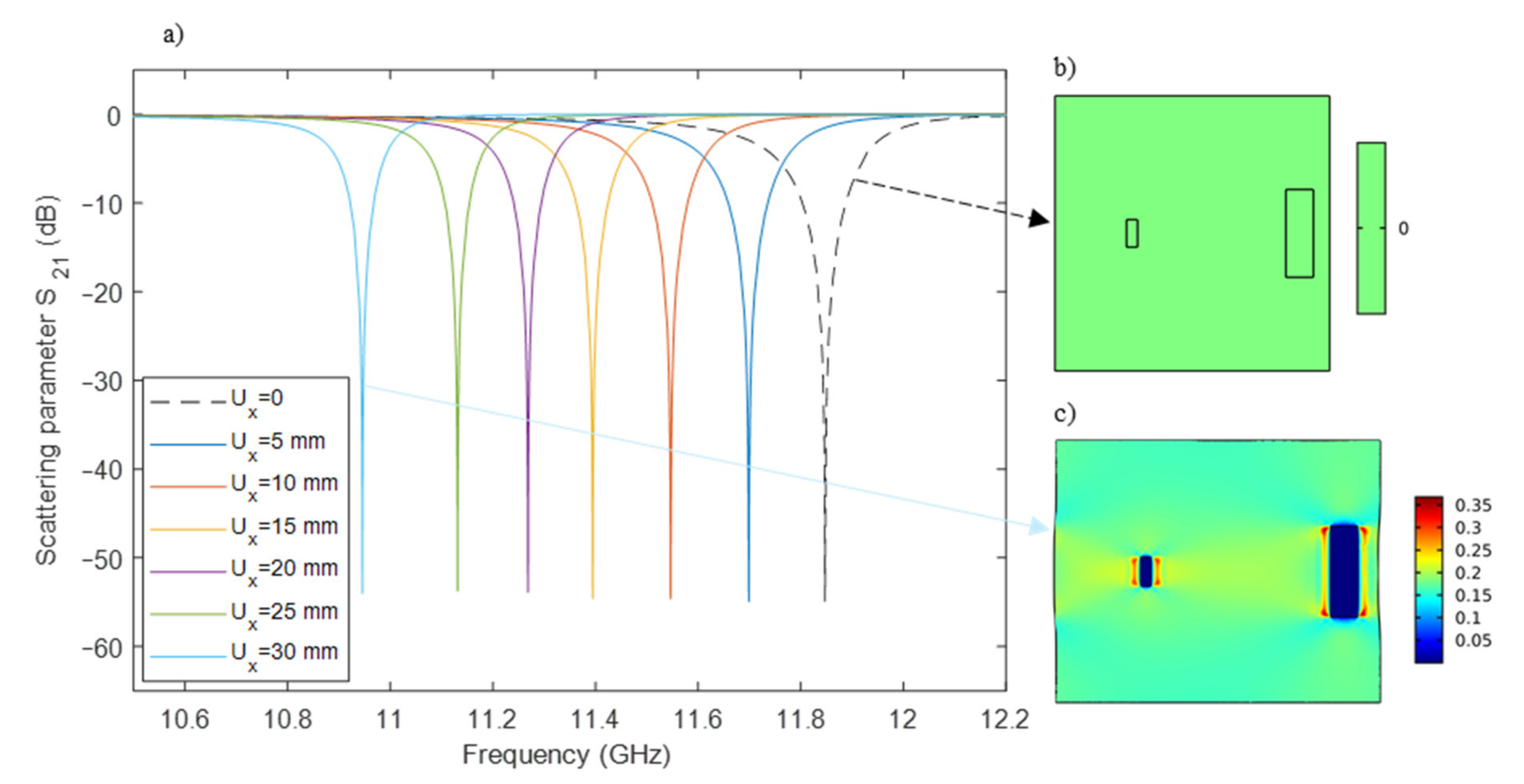
For further elaboration, the scattering parameter S21 versus frequency is presented in accordance with the applied displacement and the corresponding strains in Figure 8. It is shown that by applying deformations, there is a shift in the resonance frequency of the HSS which shows the tunability of the proposed HSS by applying deformation. Moreover, there is a huge difference in the scattering parameter S21 of the HSS at the resonance frequency of the undeformed and deformed HSSs. This demonstrated the switchability of the proposed HSS.
Given the results presented in Figure 7, Figure 8 and Table 1, we confirm the expectation that the resonance frequency of the HSS is highly sensitive to the deformation; the HSS shows the RFS of 7.59% for the highest average applied strain of 16.79%. Thus, this HSS is adequate for the purpose of tunability. Moreover, deformation considerably changes the scattering parameter S21 of the HSS. Upon applying 2.7% strain, the HSS shows a 46.5 dB increase in its scattering parameter S21 at the undeformed resonance frequency of 11.85 GHz. It is equivalent to changing the surface from opaque to transparent. In reverse, considering the scattering parameter S21 of the HSS at the undeformed state as the reference, this deformation can move the transmission peak at lower frequencies, turning the initially transparent surface into an opaque one, with a 49.3 dB transmission difference. Furthermore, the experimental results prove the elastic (mechanically reversible) behavior of the HSS under the applied deformations, which makes it a suitable choice for tunable sensors and filters.

4. Conclusions

In conclusion, aiming to achieve a multifunctional hyperelastic structured surface (HSS), we investigated different resonator geometries and utilized a Genetic Algorithm method to find an optimum design of an HSS that shows a significant change in its resonance frequency and scattering parameters by applying moderate mechanical deformations. We considered the range of 10 to 13 GHz for the working frequency. In this range, we proposed a design with simultaneous switching and resonance frequency tuning characteristics. Mechanical strains up to 16.8% can continuously tune the resonance frequency of this HSS from 11.8 GHz to 10.9 GHz. In addition to a big shift in the resonance frequency (7.6%), this HSS shows a considerable change in its scattering parameter S21. Applying an average strain of 2.7% increases the scattering parameter S21 of this design at the undeformed resonance frequency by 46.5 dB and decreases the scattering parameter S21 at frequencies lower than the undeformed resonance frequency up to 49.3 dB. As a result, by applying mechanical deformation, the opaque HSS changes to a completely transparent one and vice versa. Furthermore, we fabricated and experimentally demonstrated the efficiency of the proposed design. Other advantages of the proposed HSS is the potential capability of hyperelastic behavior (reversible under large deformations), which is also demonstrated by our experimental measurements.

Author Contributions

All authors contributed substantially to the reported work. Conceptualization, methodology, software, design of measurement set-up, validation, investigation, data curation, writing—review and editing, and visualization: R.K.M., R.N., T.G., and R.F.; prototype fabrication: R.K.M. and R.F.; writing—original draft preparation and formal analysis: R.K.M.; resources: R.N., T.G., and R.F.; supervision: R.N., T.G., and R.F. All authors have read and agreed to the published version of the manuscript.

Funding

This research received no external funding.

Institutional Review Board Statement

Not applicable.

Informed Consent Statement

Not applicable.

Data Availability Statement

The data presented in this study are available within the article.

Acknowledgments

The authors would like to express their gratitude toward Anja K. Skrivervik, head of Microwave and Antenna Group, Ecole Polytechnique Federale de Lausanne (EPFL) for the helpful discussions. The authors also acknowledge the help of Arnaud Bertsch, scientist at Microsystems Laboratory 4, Ecole Polytechnique Federale de Lausanne (EPFL) with fabrication of the hyperelastic structured surface.

Conflicts of Interest

The authors declare no conflict of interest.

References

  1. Bukhari, S.S.; Vardaxoglou, J.Y.; Whittow, W. A metasurfaces review: Definitions and applications. Appl. Sci. 2019, 9, 2727. [Google Scholar] [CrossRef] [Green Version]
  2. Ziolkowski, R.W.; Jin, P.; Lin, C.C. Metamaterial-inspired engineering of antennas. Proc. IEEE 2010, 99, 1720–1731. [Google Scholar] [CrossRef]
  3. Fang, N.; Lee, H.; Sun, C.; Zhang, X. Sub–diffraction-limited optical imaging with a silver superlens. Science 2005, 308, 534–537. [Google Scholar] [CrossRef] [PubMed] [Green Version]
  4. Lee, Y.; Kim, S.J.; Park, H.; Lee, B. Metamaterials and metasurfaces for sensor applications. Sensors 2017, 17, 1726. [Google Scholar] [CrossRef] [PubMed] [Green Version]
  5. Burch, J.; Di Falco, A. Surface topology specific metasurface holograms. ACS Photonics 2018, 5, 1762–1766. [Google Scholar] [CrossRef]
  6. Butt, H.; Montelongo, Y.; Butler, T.; Rajesekharan, R.; Dai, Q.; Shiva-Reddy, S.G.; Wilkinson, T.D.; Amaratunga, G.A. Carbon nanotube based high resolution holograms. Adv. Mater. 2012, 24, OP331–OP336. [Google Scholar] [CrossRef]
  7. Khorasaninejad, M.; Chen, W.T.; Devlin, R.C.; Oh, J.; Zhu, A.Y.; Capasso, F. Metalenses at visible wavelengths: Diffraction-limited focusing and subwavelength resolution imaging. Science 2016, 352, 1190–1194. [Google Scholar] [CrossRef] [Green Version]
  8. Rajasekharan Unnithan, R.; Sun, M.; He, X.; Balaur, E.; Minovich, A.; Neshev, D.N.; Skafidas, E.; Roberts, A. Plasmonic colour filters based on coaxial holes in aluminium. Materials 2017, 10, 383. [Google Scholar] [CrossRef] [PubMed]
  9. He, X.; Liu, Y.; Ganesan, K.; Ahnood, A.; Beckett, P.; Eftekhari, F.; Smith, D.; Uddin, M.H.; Skafidas, E.; Nirmalathas, A.; et al. A single sensor based multispectral imaging camera using a narrow spectral band color mosaic integrated on the monochrome CMOS image sensor. APL Photonics 2020, 5, 046104. [Google Scholar] [CrossRef]
  10. Grady, N.K.; Heyes, J.E.; Chowdhury, D.R.; Zeng, Y.; Reiten, M.T.; Azad, A.K.; Taylor, A.J.; Dalvit, D.A.; Chen, H.T. Terahertz metamaterials for linear polarization conversion and anomalous refraction. Science 2013, 340, 1304–1307. [Google Scholar] [CrossRef] [Green Version]
  11. Cure, D.; Weller, T.M.; Miranda, F.A. Study of a low-profile 2.4-GHz planar dipole antenna using a high-impedance surface with 1-D varactor tuning. IEEE Trans. Antennas Propag. 2012, 61, 506–515. [Google Scholar] [CrossRef]
  12. Kim, M.; Kim, I.; Jang, J.; Lee, D.; Nam, K.T.; Rho, J. Active color control in a metasurface by polarization rotation. Appl. Sci. 2018, 8, 982. [Google Scholar] [CrossRef] [Green Version]
  13. Pryce, I.M.; Aydin, K.; Kelaita, Y.A.; Briggs, R.M.; Atwater, H.A. Highly strained compliant optical metamaterials with large frequency tunability. Nano Lett. 2010, 10, 4222–4227. [Google Scholar] [CrossRef] [PubMed] [Green Version]
  14. Yuan, H.; Zhu, B.O.; Feng, Y. A frequency and bandwidth tunable metamaterial absorber in x-band. J. Appl. Phys. 2015, 117, 173103. [Google Scholar] [CrossRef]
  15. Li, Y.; Lin, J.; Guo, H.; Sun, W.; Xiao, S.; Zhou, L. A tunable metasurface with switchable functionalities: From perfect transparency to perfect absorption. Adv. Opt. Mater. 2020, 8, 1901548. [Google Scholar] [CrossRef]
  16. Ren, Z.; Chang, Y.; Ma, Y.; Shih, K.; Dong, B.; Lee, C. Leveraging of MEMS technologies for optical metamaterials applications. Adv. Opt. Mater. 2020, 8, 1900653. [Google Scholar] [CrossRef]
  17. Sharma, M.; Hendler, N.; Ellenbogen, T. Electrically switchable color tags based on active liquid-crystal plasmonic metasurface platform. Adv. Opt. Mater. 2020, 8, 1901182. [Google Scholar] [CrossRef]
  18. Lu, F.; Liu, B.; Shen, S. Infrared wavefront control based on graphene metasurfaces. Adv. Opt. Mater. 2014, 2, 794–799. [Google Scholar] [CrossRef]
  19. Ding, L.; Luo, X.; Cheng, L.; Thway, M.; Song, J.; Chua, S.J.; Chia, E.E.; Teng, J. Electrically and thermally tunable smooth silicon metasurfaces for broadband terahertz antireflection. Adv. Opt. Mater. 2018, 6, 1800928. [Google Scholar] [CrossRef]
  20. Gao, B.; Yuen, M.M.; Ye, T. Ferrite film loaded frequency selective metamaterials for sub-GHz applications. Materials 2016, 9, 1009. [Google Scholar] [CrossRef] [Green Version]
  21. Wang, Z.; Jing, L.; Yao, K.; Yang, Y.; Zheng, B.; Soukoulis, C.M.; Chen, H.; Liu, Y. Origami-based reconfigurable metamaterials for tunable chirality. Adv. Mater. 2017, 29, 1700412. [Google Scholar] [CrossRef] [PubMed]
  22. Nauroze, S.A.; Novelino, L.S.; Tentzeris, M.M.; Paulino, G.H. Continuous-range tunable multilayer frequency-selective surfaces using origami and inkjet printing. Proc. Natl. Acad. Sci. USA 2018, 115, 13210–13215. [Google Scholar] [CrossRef] [PubMed] [Green Version]
  23. Azemi, S.N.; Ghorbani, K.; Rowe, W.S. A reconfigurable FSS using a spring resonator element. IEEE Antennas Wirel. Propag. Lett. 2013, 12, 781–784. [Google Scholar] [CrossRef]
  24. Arritt, B.; Adomanis, B.; Khraishi, T.; Smith, D. Parametric analysis of the strain-dependent behavior of a metamaterial electric resonator. Appl. Phys. Lett. 2010, 97, 191907. [Google Scholar] [CrossRef] [Green Version]
  25. Arritt, B.J.; Smith, D.R.; Khraishi, T. Equivalent circuit analysis of metamaterial strain-dependent effective medium parameters. J. Appl. Phys. 2011, 109, 073512. [Google Scholar] [CrossRef] [Green Version]
  26. Karimi Mahabadi, R.; Goudarzi, T.; Fleury, R.; Sohrabpour, S.; Naghdabadi, R. Challenges in finite element analysis of a deformable metasurface unit cell using COMSOL Multiphysics. Presented at the Iberian COMSOL Multiphysics Conference, Malaga, Spain, 28 June 2019. [Google Scholar]
  27. COMSOL Multiphysics®; v.5.4. 2020; COMSOL EPFL: Lausanne, Switzerland, 2020; Available online: www.comsol.com.
  28. Smith, D.R.; Pendry, J.B. Homogenization of metamaterials by field averaging. J. Opt. Soc. Am. B 2006, 23, 391–403. [Google Scholar] [CrossRef]
  29. Hollister, S.J.; Kikuchi, N. A comparison of homogenization and standard mechanics analyses for periodic porous composites. Comput. Mech. 1992, 10, 73–95. [Google Scholar] [CrossRef] [Green Version]
  30. Ogden, R.W. Non-Linear Elastic Deformations, 1st ed.; Dover Publication Inc.: Mineola, NY, USA, 1997. [Google Scholar]
  31. Li, J.; Shah, C.M.; Withayachumnankul, W.; Ung, B.S.Y.; Mitchell, A.; Sriram, S.; Bhaskaran, M.; Chang, S.; Abbott, D. Mechanically tunable terahertz metamaterials. Appl. Phys. Lett. 2013, 102, 121101. [Google Scholar] [CrossRef] [Green Version]
  32. Aksu, S.; Huang, M.; Artar, A.; Yanik, A.A.; Selvarasah, S.; Dokmeci, M.R.; Altug, H. Flexible plasmonics: Flexible plasmonics on unconventional and nonplanar substrates (Adv. Mater. 38/2011). Adv. Mater. 2011, 23, 4421. [Google Scholar] [CrossRef]
  33. Liu, N.; Guo, H.; Fu, L.; Kaiser, S.; Schweizer, H.; Giessen, H. Three-dimensional photonic metamaterials at optical frequencies. Nat. Mater. 2008, 7, 31–37. [Google Scholar] [CrossRef]
  34. Han, N.R.; Chen, Z.C.; Lim, C.S.; Ng, B.; Hong, M.H. Broadband multi-layer terahertz metamaterials fabrication and characterization on flexible substrates. Opt. Express 2011, 19, 6990–6998. [Google Scholar] [CrossRef] [PubMed]
  35. Fan, K.; Strikwerda, A.C.; Zhang, X.; Averitt, R.D. Three-dimensional broadband tunable terahertz metamaterials. Phys. Rev. B 2013, 87, 161104. [Google Scholar] [CrossRef] [Green Version]
  36. Bückmann, T.; Stenger, N.; Kadic, M.; Kaschke, J.; Frölich, A.; Kennerknecht, T.; Eberl, C.; Thiel, M.; Wegener, M. Tailored 3D mechanical metamaterials made by dip-in direct-laser-writing optical lithography. Adv. Mater. 2012, 24, 2710–2714. [Google Scholar] [CrossRef] [PubMed]
  37. Walia, S.; Shah, C.M.; Gutruf, P.; Nili, H.; Chowdhury, D.R.; Withayachumnankul, W.; Bhaskaran, M.; Sriram, S. Flexible metasurfaces and metamaterials: A review of materials and fabrication processes at micro-and nano-scales. Appl. Phys. Rev. 2015, 2, 011303. [Google Scholar] [CrossRef]
  38. Befahy, S.; Lipnik, P.; Pardoen, T.; Nascimento, C.; Patris, B.; Bertrand, P.; Yunus, S. Thickness and elastic modulus of plasma treated PDMS silica-like surface layer. Langmuir 2010, 26, 3372–3375. [Google Scholar] [CrossRef]
  39. Ohishi, T.; Noda, H.; Matsui, T.S.; Jile, H.; Deguchi, S. Tensile strength of oxygen plasma-created surface layer of PDMS. J. Micromech. Microeng. 2016, 27, 015015. [Google Scholar] [CrossRef]
Figure 1. Percentage of the resonance frequency shift (RFS) under uniaxial deformation with 1% mechanical strain in x direction for the unit cells with different resonator geometries (a) split ring with a bar (b) modified-I (c) split rings (d) bow-tie (e) four-cut split ring (f) parallel bars.
Applsci 11 02255 g001
Figure 2. Flowchart of the optimization procedure for the hyperelastic structured surface (HSS) using a genetic algorithm method.
Applsci 11 02255 g002
Figure 3. Schematic view of the optimal design with dimensions in mm and percentage of the resonance frequency shift (RFS) under uniaxial deformation with 1% mechanical strain in x direction.
Applsci 11 02255 g003
Figure 4. X-component of the computed displacement field for a boundary displacement of 30 mm in the x direction applied to the right edge of (a) the entire finite HSS and (b) its center unit cell. The left edge is fixed.
Applsci 11 02255 g004
Figure 5. Fabrication process: (a) cutting the Curtonic foil using a Roland® vinyl cutter, (b) removing the excess copper parts, (c) plasma treatment of the PDMS film. (d) The fabricated HSS prototype on a transparent plastic sheet.
Applsci 11 02255 g005
Figure 6. Measurement set-up: (a) the whole set-up, (b) zoomed view of the mechanical set up, (c) standard gain horn antenna, (d) monopole antenna.
Applsci 11 02255 g006
Figure 7. Measured resonance frequency shift of the proposed HSS with various applied displacements (in mm). The loading and measurement procedure is repeated three times, indicated by the Roman numbers.
Applsci 11 02255 g007
Figure 8. (a) Scattering parameter S21 of the proposed HSS with various applied displacements (in mm) to the HSS. Strain contours of the (b) undeformed and (c) deformed unit cells.
Applsci 11 02255 g008
Table 1. Comparison of the HSS respond under the applied displacements.
U x
(mm)
ε ¯ x x
(%)
f 0
(GHz)
RFS
(GHz)
R F S f 0 Underformed × 100
(%)
Δ S 21 @ f 0 Underformed
(dB)
Δ S 21 @ f 0
(dB)
52.6611.69−0.161.3546.5−49.3
105.3611.55−0.302.5347.8−45.1
158.1011.39−0.463.8848.0−45.6
2010.8811.27−0.584.8948.0−43.6
2513.7011.13−0.726.0848.0−45.8
3016.7910.95−0.907.5948.0−49.3
Publisher’s Note: MDPI stays neutral with regard to jurisdictional claims in published maps and institutional affiliations.