Abstract
Robust control techniques for power converters are becoming more attractive because they can meet with most demanding control goals like uncertainties. In this sense, the Takagi-Sugeno (T-S) fuzzy controller based on linear matrix inequalities (LMI) is a linear control by intervals that has been relatively unexplored for the output-voltage regulation problem in switching converters. Through this technique it is possible to minimize the disturbance rejection level, satisfying constraints over the decay rate of state variables as well as the control effort. Therefore, it is possible to guarantee, a priori, the stability of the large-signal converters in a broad operation domain. This work presents the design of a fuzzy control synthesis based on a T-S fuzzy model for non-minimum phase dc-dc converters, such as boost and buck-boost. First, starting from the canonical bilinear converters expression, a Takagi-Sugeno (T-S) fuzzy model is obtained, allowing to define the fuzzy controller structure through the parallel distributed compensation technique (PDC). Finally, the fuzzy controller design based on LMIs is solved for the defined specification in close loop through MATLAB toolbox LMI. Simulations and experimental results of a 60 W prototype are presented to verify theoretical predictions.
1. Introduction
DC-DC switching converters are one of the most classical power electronics circuits used to adapt non-regulated sources to different load requirements in many applications [1]. Hence, from telecommunication and computers to renewable energies equipment in which the voltages or currents controls are required, a DC-DC converter is necessary. In fact, during the last years dc-dc converters have been improved constantly, providing high performance at very high switching frequencies for a broad input and output voltages.
Nonetheless, based on the higher non-linear nature, or even due to the existence of parametric uncertainties, among others, switching converters present important dynamic complexities. Thus, to deal with these non-linearity issues and reach a good voltage regulation performance, classic linear feedback approaches have been commonly applied [1,2,3]. Though linear feedback control methods are accepted by the industry, it has been proven that these classic strategies also present malfunctioning or unstable behaviors under large disturbances. Basically, the latter is result from the fact that classical approaches do not consider the non-linearities of the converter. With the aim to overcome these limitations, researchers have been exploring other control techniques that contemplate the non-linearities and uncertainty parameters in switching DC-DC converters. For instance, robust control has been widely used during the last years attracting the interest in the power electronics field [4,5,6]. Unlike non-linear control and conventional linear control, robust control ensures a minimum of features regarding uncertainties in DC-DC converters.
In [7,8], the design of a robust state-feedback control for a minimum-phase buck converter is proposed. The works showed the use of simple conditions for LMIs guaranteeing the stability of the system as well as the disturbance rejection for the close-loop control. Nevertheless, they do not describe any experimental results and only verify the effectiveness of the proposed method through simulations. Similarly, in [9] it is also presented the design of a LMI-based robust control law by state-feedback, but in this case, applied to a non-minimum phase boost converter. This control method takes into consideration uncertainties and non-linearities of the converter, which are modeled like a convex polytope. This allows LMIs constraints to robustly guarantee a certain level of disturbances rejection and a specific location region for the poles. Contrarily to [7,8,9], presents precise experimental results in a boost prototype which are in agreement with the design requirements in spite of the uncertainties. Finally, in [10,11,12] other powerful LMI approaches are proposed for a boost regulator control, which allows to consider uncertainty in the converter and ensure its stability among different operation points due to the inclusion of a bilinear dynamic. The accuracy of these approaches is verified through an experimental prototype, which shows good similarity with theoretical predictions.
Moreover, over the last decades, the application of fuzzy logic in control systems has drawn the attention of the scientific community as well as numerous technicians of industrial processes. This methodology can be very useful when processes are rather complex for their analysis through conventional techniques, or when the available information is inaccurately or uncertainly interpreted. Despite the advantages of the fuzzy logic based controls there is a lack of tools for the prediction of the stability and robustness for closed-loop systems, generating some criticism in the automatic control field. For this reason, in the last few years, the design of more accurately fuzzy controllers, particularly the Takagi-Sugeno (T-S) based model, have registered significant breakthroughs thanks to the Linear Matrix Inequalities theory (LMI) and Lyapunov stability analysis [13,14].
In control engineering, the Model-Based Fuzzy Control (MBFC), which uses the concept of parallel distributed compensation, has been catalogued as an effective and systematic approach for highly non-linear control systems. Based on linear matrix inequalities and convex optimization techniques, this approach allows to secure better stability, performance and robustness properties and some established benefits over a wide operation region [14,15,16]. Thus, applied to DC-DC converters, the first references are found in [17,18]. In [17], a LMI-based integral fuzzy control for voltage regulation of a basic buck converter with zero-voltage switching (ZVS) is proposed, guaranteeing exponential stability in a broad field of operation. Afterwards in [18] a design methodology of a fuzzy control is presented for a boost converter, ensuring large-signal stability. In particular, through Lyapunov theory, the sufficient-stability conditions in terms of LMIs are adopted considering uncertainty in the parameters. In addition to this, relaxed conditions in the belonging functions are proposed with the purpose of relieving the conservatism of the presented approach. Nonetheless, this work does not describe any experimental prototype and only verifies the effectiveness of the method for a boost converter through simulations. Finally, in [19] an fuzzy-control design method is presented for a DC-DC buck converter with input restrictions. Likewise, this work does not show experimental results.
Based on the previous statements, the motivation of this work consists in the use of a simple MBFC methodology for the output voltage regulation of two non-minimum phase DC-DC converters, such as boost and buck-boost. In [20,21] first designs of control synthesis proposed for DC-DC converters through simulations were performed in Matlab. Therefore, through simulations, it is proven that it is possible to ensure the constraints compliance such as: decay rate and effort control. Besides, starting from the obtained results, it is possible to observe at the same time that a minimum attenuation level is guaranteed between a load current disturbance and regulated output voltage. It is worth noticing, that through the application of the proposed strategy it is possible to consider the saturation of the duty cycle, which allows to attenuate the response of the control signal and maintain within the proper interval. Finally, through a simple and analogue implementation, experimental results of the boost converter are presented, verifying the advantages of the proposed method compared to a non-fuzzy LMI robust control.
The rest of the paper is organized as follows. In Section 2, MBFC theory is discussed, which will be used to build the T-S fuzzy models based on buck-boost and boost converters models. Then, in Section 3 the LMIs requirements for design are presented, taking into account the concept of CDP. Then, in Section 4, two examples of fuzzy control based on LMI design are presented for the output voltage regulation problem of buck-boost and boost converters, guaranteeing a certain level of disturbance rejection, a decay rate and control effort limitation. In addition, in this section it is presented a comparison of the proposed controller and a non-fuzzy LMI controller. Experimental results for the boost converter case are also shown in Section 4. Finally, in Section 5 the main conclusions are presented.
2. Takagi-Sugeno Fuzzy Modeling of DC-DC Converters
The construction of a mathematical model to describe the dynamic of a system in study is not easy. Since the model must include all the relevant characteristics associated with the dynamic. In addition, the mathematical expression is complex due to the non-linear nature of the system, making that a good approximation becomes essential. T-S fuzzy approach is a modeling methodology that considers the dynamics of a system as real as the exact model, through the implementation of several linear models. The main characteristic of this methodology is the formulation of the local dynamics of each fuzzy implication by a linear model [22]. The complete fuzzy model of the system is achieved by fuzzy blending of the linear system models. In this section, the averaged bilinear model and the Takagi-Sugeno fuzzy representation in a buck-boost and a boost converter are introduced.
2.1. T-S Fuzzy Model of a Buck-Boost Converter
Figure 1 shows the well-known circuit of a buck-boost converter, which is capable to step-up/down the output voltage from the input one . R represents the converter nominal load, while L and C stand for the inductance and capacitance values, respectively. Besides, source represents the load current disturbance.
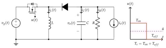
Figure 1.
Schematic circuit of a buck-boost converter.
The state variables considered for the analysis are the inductor current and the capacitor voltage . The binary signal turn the MOSFET ON when and OFF when at a constant switching frequency , such as shown in Figure 1. The step-up/down operation of the converter in steady state depends of the ratio , which represents the duty cycle d of the converter. It is further assumed that the converter operates in continuous conduction mode (CCM), and without parasitic elements. The following expression shows the state-space bilinear model of the buck-boost converter [23]:
where , , are the incremental averaged values of the state vector, input vector, and disturbance inputs around equilibrium values X, U and W, respectively. Besides, represents the controlled output . Thus, based on the circuit of Figure 1, the expression (1) can be written as:
where is the complementary steady-state duty cycle.
In order to ensure zero steady state error in the output voltage , a new state variable has been introduced in the model (2). This integral function forces when , where is the voltage reference.
Takagi-Sugeno Fuzzy representation allows to describe the dynamics of a non-linear system by means of a set of local linear models based on fuzzy rules, which are smoothly connected by membership functions. The rule set of a T-S fuzzy model is written as:
where r is the number of the submodels, are system matrices of the i-th linear submodel, are input matrices, are disturbance inputs matrices, are controlled output matrices, is the global state-space vector, is the input vector, is the disturbance input vector, is the controlled output vector, are the fuzzy sets, and are the scheduling vector or premise variables [13]. On the other hand, are the membership functions of the fuzzy sets and the weight contribution of the rule. The final outputs of the fuzzy systems are obtained as the weighted sum of all the local contributing submodels, leading to:
where, , , for .
From the incremental bilinear model (2), the T-S fuzzy model of the buck-boost converter can be obtained [20,21]. With the selection of the scheduling variables , in most cases the state variables, the local linear models necessary for the construction of the total fuzzy model are obtained from the extreme values of . These extreme values will allow defining the rule base of the fuzzy model, as well as the membership functions necessary for the fuzzy weighting of the locally valid linear submodels associated to each implication. Thus, the T-S fuzzy model approximation of the buck-boost converter can be constructed using the following steps:
- Find the system scheduling variables :being .
- Calculate local linear models from extreme values of . For the ordered pairs: , , , is obtained:
- Design the membership functions. From the extreme values of , the membership functions are defined as follows:
- Build up the rule-base of the T-S fuzzy model. Fuzzy model of the buck-boost converter is defined by the following four rules:
It is worth mentioning that in the literature on fuzzy controllers, membership functions with different shapes such as triangular, trapezoidal, Gaussian, among others, have been used. In this paper, for the sake of simplicity in practice, triangular membership functions were used.
Once the above steps are performed, the total fuzzy model of the converter can be expressed as:
Since and , the fuzzy model (9) can be rewritten as:
Therefore, the buck-boost converter fuzzy dynamics can be written as:
where
It should be noted that (9) represents exactly the model bilinear (2) in the polytopic region which is shown in Figure 2.
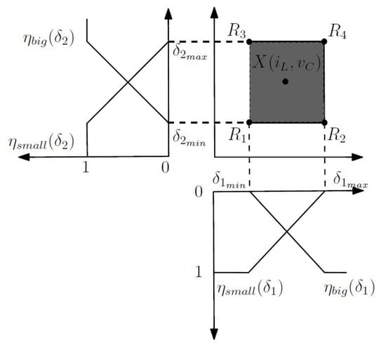
Figure 2.
T-S Fuzzy representation of the buck-boost converter.
The model (11) will be used in section IV to find the T-S Fuzzy Control of the buck-boost converter. It is worth noting that the procedure can be used if there are more scheduling variables.
2.2. T-S Fuzzy Model of a Boost Converter
Figure 3 shows the schematic of a boost converter. As in the previous section, the converter operates in CCM and parasitic resistances in the inductor and the capacitor are sufficiently small to be neglected.
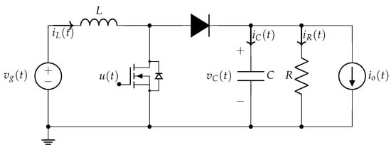
Figure 3.
Schematic circuit of a boost converter.
The incremental bilinear model of the boost converter has the form presented in (1). The values of vectors and state space matrices are written as follows:
Applying the methodology of the previous section, the T-S fuzzy model of the boost converter can be expressed as:
where the weight contribution of each fuzzy rule , have the same behavior as for the buck-boost converter case (12).
In the next section, the proposed LMI-fuzzy control strategy is explained. This control law consists of a weighted sum of the feedback gains of each submodel, which has constraints such as: perturbation rejection level, decay rate of state variables and control effort.
3. LMI Performance Requeriments for Fuzzy Controllers
The design procedure of the controller is based on the Parallel Distributed Compensation technique (PDC), which is used to design state feedback controllers based on T-S fuzzy models [13]. This metholodology consists in associating each control rule with the corresponding rule of the fuzzy model, as follows:
where are lineal feedback gain vectors associated with each rule. Then, the output controller is deduced as:
Substituting the control law (16) in the fuzzy model (4), the closed loop system dynamics is given by:
In order to find the feedback gain vectors properly in an operating range, Lyapunov stability and performance constraints in form of LMIs are imposed. In this way, these performance constraints, taken from [13], are expressed by the following theorems.
Theorem 1.
The system defined by (4) is quadratically stable for some feedback gains F and if there is a common positive definite matrixW and Y such that [13]:
where I is the identity matrix, and .
Theorem 2.
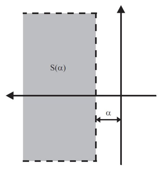
The eigenvalues of in each linear fuzzy system are inside the region S( (see Figure 4) if there is a common positive definite matrix W such that [13]:
Figure 4.
Pole location region .
being so that for , it is had .
Theorem 3.
Assume that initial condition x(0) is known. The constraint ≤ μ is enforced at all times 0 if the LMIs (20) hold [13]:
where and .
A detailed proof of the Theorems 1, 2 and 3 are shown in [13]. Thus, from the previous LMIs, the procedure proposed is to find the minimum norm between the disturbance input and the regulated output, ensuring at the same time stability in a wide domain of operation. The synthesis of the LMI-Fuzzy control can be performed using the following optimization algorithm:
The solution of this optimization program with its corresponding LMIs will provide the set of feedback gains . The solution of this algorithm can be readily solved by standard interior-point methods using Matlab [24].
4. Simulations and Experimental Results
This section presents two examples of LMI-Fuzzy control design applied to the non-minimum phase dc-dc converters for the output voltage regulation problem. In the first case, a fuzzy control is applied to a buck-boost converter, taking into account the T-S fuzzy model described in Section 2.1. The second example proposes a fuzzy control applied to a boost converter with its corresponding T-S fuzzy model Section 2.2. Both control examples ensure fulfilment of the LMI restrictions on decay rate and control effort, which correspond to the LMIs (19) and (20), optimizing the rejection of disturbances in the load current (18), by applying the algorithm (21). In addition, this section shows some simulations in PSIM of both examples, where the proposed approach is compared with non-fuzzy LMI robust controller. Finally, for the case of the step-up converter, the validity of the design procedure is demonstrated through experimental results.
4.1. LMI-Fuzzy Control of a Buck-Boost Converter
In this first example, as mentioned above, the design of an LMI-Fuzzy control law is shown as an alternative to the voltage regulation of the buck-boost converter, based on the fuzzy model (11), whose set of parameters is shown in Table 1. The values of the state variables in steady state, according to the expression (2), corresponds to = A, . Thus, the simulation prototype of the converter is considered for processes smaller than 60 W, taking into account a load resistance R = 10 .

Table 1.
Buck-Boost converter parameters.
The goal of control synthesis is to find a vector of feedback gains such that the norm () is minimized, satisfying the constraints on the decay rate and the control effort for the four linear submodels that build the T-S fuzzy model (11). The chosen controller parameter values are specified in Table 2.
Table 2.
Controller Parameters.
It should be noted that the decay rate that has been chosen corresponds to a maximum time of establishment of s, while the threshold limit value for the saturation of the control signal, corresponds to . In this way, solving the optimization algorithm (21) through MATLAB’s LMI toolbox [24], the fuzzy state feedback gains are obtained :
This controller ensures a gain of the output voltage with respect to the output current disturbance of , which is equivalent to 2.2789 dB. In a general case, the corresponding fuzzy law produced by the duty cycle will be given by:
As mentioned at the beginning of the section, in order to evaluate the operation and robustness of the proposed methodology, the results are compared with a LMI robust linear control law, applying the approach proposed in [9]. For this reason, the vector of feedback gains that is obtained corresponds to:
The gain of the output voltage with respect to the output current disturbance of this controller is , corresponding to dB. For this case, the generated equivalent law is given by:
Through the LMI-Fuzzy control schematic diagram for the converter buck-boost from Figure 5, some simulations of the dynamic behavior of the converter in the presence of changes in the load and in the input voltage were carried out in PSIM inside and outside the nominal conditions, taking into account the values in Table 1 and Table 2.
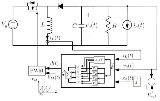
Figure 5.
Circuital diagram of a buck-boost converter with the LMI-Fuzzy control.
Figure 6a depicts waveforms of the output voltage of the buck-boost converter with LMI-Fuzzy control, under nominal conditions and in the face of changes in load current of 2 A. It can be seen that the controller regulates the voltage smoothly at V after a short transient period, equivalent to a time constant of 4 ms (), which is a value that is above the minimum guaranteed decay rate that is (). In Figure 6b, with the same previous conditions, the output voltage response is shown with the LMI robust control proposed in [9]. It is worth noting that the voltage response presents a time constant of approximately 5 ms, equivalent to a decay rate of , as expected with the minimum guaranteed decay rate. However, comparing the two previous results, it can be highlighted that the LMI-Fuzzy control law presents better dynamic behavior than the LMI robust control law, since it shows a better decay rate and disturbances rejection.
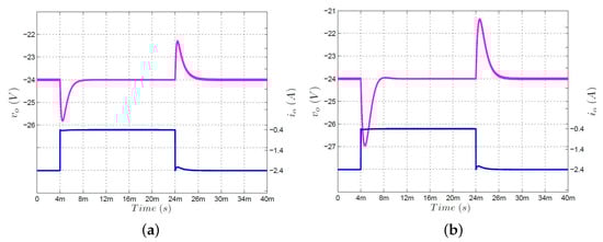
Figure 6.
Simulated response of the buck-boost converter under output current transients of 2 A with the LMI-Fuzzy controller () and LMI robust controller (). (a) Voltage response with . (b) Voltage response with [9].
On the other hand, in Figure 7 the dynamic behavior of the buck-boost converter is described under input voltage variations with the laws LMI-Fuzzy and LMI robust. Namely, an input-voltage step from 24 V to 22 V is applied at ms and returned at ms. Also, it can be observed that for both controllers the output voltage response presents decay rates greater than the guaranteed minimum. . As in the previous case, the fuzzy control law presents better dynamic behavior, both in decay rate and in disturbances rejection.
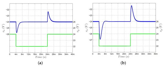
Figure 7.
Simulated response of the buck-boost converter under input voltage transients of 2 V with the LMI-Fuzzy controller () and LMI robust controller (). (a) Voltage response with . (b) Voltage response with [9].
In the next subsection, the design of a LMI-Fuzzy control will be presented for the case of a boost converter.
4.2. LMI-Fuzzy Control of a Boost Converter
As in the previous subsection, the regulation of the output voltage for a step-up converter is presented, taking into account its corresponding fuzzy model (12). This design consists of solving the optimization algorithm (21) for the set of parameters shown in Table 3, where the nominal load of the converter is equal to 10 and the complementary duty cycle in steady state is equal to .
Table 3.
Boost converter parameters.
As it has been established, the control synthesis procedure consists of finding a vector of feedback gains such that the parameter is minimized in the LMI (20), while the constraints on the decay rate () and the control effort are satisfied for the four linear submodels that build the T-S fuzzy model (12). The values of the control parameters, i.e., , are the same used for the case of the buck-boost converter. In order to demonstrate the advantage of the fuzzy control, as in the previous example, a comparison is made with the results of the LMI robust linear control law proposed in [9]. Therefore, for the set of parameters in Table 2 and Table 3, the feedback gain vectors and are obtained. In this way, for the case of LMI-Fuzzy control, the fuzzy state feedback gains correspond to:
This controller ensures a gain of the output voltage with respect to the output current disturbance of (0.1250 dB). Furthermore, it is shown that the matrix P is positive definite, ensuring that the asymptotic stability of the converter is fulfilled, as shown in (25).
The LMI robust feedback gain vector obtained corresponds to:
This controller ensures a minimum level of disturbance rejection equivalent to the inverse of (7.2 dB).
In order to verify the dynamic behavior of the boost converter under the laws LMI robust (26) and LMI-Fuzzy (24), some numerical simulations were performed via PSIM.
Figure 8a depicts waveforms of the output current and the regulated voltage of the converter, controlled by the feedback gains (24). The bottom waveform shows a change from A to of the output current at ms, and the opposite transition at ms. As expected, the settling time is ms below, which corresponds to the minimum decay rate set in the Table 2. Now, the same current disturbance is applied to the boost converter controlled by the feedback gain (26), where it can be seen from the waveform that the settling time is once again within the chosen design limit. As in the case of the buck-boost converter, it is worth noting that the results of the LMI-Fuzzy control show better dynamic behaviour than the LMI robust control, both in terms of settling time and disturbance rejection. Figure 9a,b illustrate the responses of the output voltage to an input voltage variation, for both the law of LMI-Fuzzy control and the law of LMI robust control, respectively. The input voltage changes from 12 V to 10 V at ms and returns to 12 V at ms. Again, the waveforms have a settling time below the minimum set decay rate. Also, it can be observed that the disturbance rejection is better in the case of LMI-Fuzzy control than in the LMI robust control.
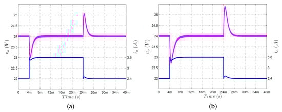
Figure 8.
Simulated response of the boost converter under output current transients of 2 A with the LMI-Fuzzy controller () and LMI robust Controller (). (a) Voltage response with . (b) Voltage response with [9].
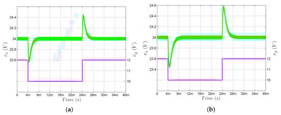
Figure 9.
Simulated response of the boost converter under input voltage transients of 2 V with the LMI-Fuzzy controller () and LMI robust Controller (). (a) Voltage response with . (b) Voltage response with [9].
In order to verify the theoretical predictions of the LMI-Fuzzy control and LMI robust control, an experimental prototype of the boost converter has been implemented whose characteristics are shown in Table 3. Figure 10 shows the circuit diagram of the prototype with the feedback structure that was used for the LMI-Fuzzy control, where it can be seen that the measurement of the current is carried out through the shunt resistance , with a value of 25 m; also a differential amplifier INA139 was used.
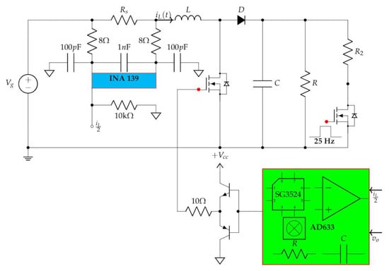
Figure 10.
Circuit diagram of a boost converter with the proposed LMI-Fuzzy control.
The power stage of boost converter used for the application of both controllers is illustrated in Figure 11. This has been implemented using an IRFP150NPBF mosfet, and a MBR745 Schottky diode, which are activated by a PWM signal generated by the UC3524 regulator through a totem-pole configuration driver. Note that the output variables are: the current measured in the inductor and the output voltage of the converter , while the inputs correspond to the duty cycle signal and the supply signal . On the other hand, the implementation of the LMI-Fuzzy control is illustrated in Figure 12a,b. Both figures show the top sides of the printed circuit boards used in the tests. The Figure 13a,b illustrate the detailed circuits of the printed circuit boards of the control law (24). The circuit diagram in Figure 13a, is responsible for compute the membership functions (8) and the normalized weights of contribution of the rules (12), while the circuit diagram in Figure 13b calculates the linear combination (22) named total T-S fuzzy controller. Both control laws, i.e., and , were implemented with OPA4131 operational amplifiers. It is worth noting that the implementation of the analog LMI-Fuzzy controller is much more complex, since it requires more operational amplifiers and AD633 multipliers.
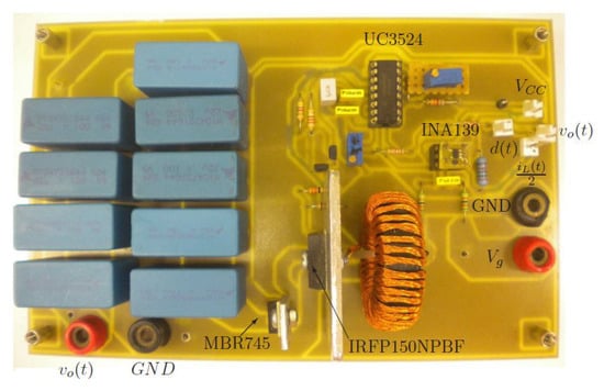
Figure 11.
Boost converter prototype.
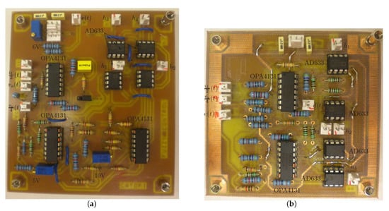
Figure 12.
Practical LMI-Fuzzy control implementation. (a) Printed circuit board for the calculate membership functions and normalized weights. (b) Printed circuit board for the calculate total T-S fuzzy controller.
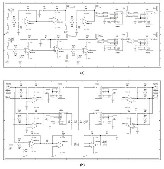
Figure 13.
Detailed circuit implementation of the LMI-Fuzzy Control. (a) Circuit diagram for the calculate membership functions and normalized weights. (b) Circuit diagram for the calculate total T-S fuzzy controller.
Figure 14a,b show the transient responses of the output voltage in the presence of a A load current disturbance, for the controllers (24) and (26), respectively. These experimental results and the previous simulated waveforms of Figure 8a,b are in very good agreement. The load current changes in the prototype were carried out by means of a voltage-controlled switch, such as shown in the circuit diagram of the converter in Figure 10. Furthermore, It was verified the response of the controllers and to a supply voltage change. The experimental result, shown in Figure 15 accurately verifies the simulations shown in Figure 9.
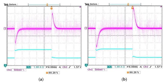
Figure 14.
Experimental response of the boost converter under input voltage transients of 2 V with the LMI-Fuzzy controller () and LMI robust Controller (). (a) Voltage response with . (b) Voltage response with [9].
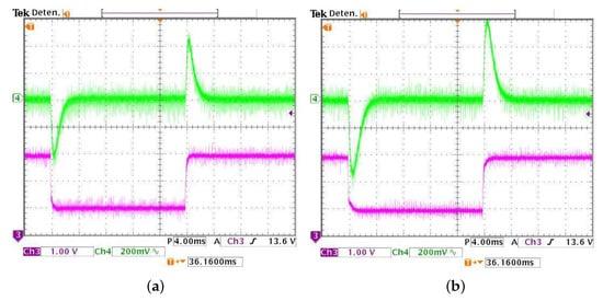
Figure 15.
Experimental response of the boost converter under input voltage transients of 2 V with the LMI-Fuzzy controller () and LMI robust Controller (). (a) Voltage responde with . (b) Voltage response with [9].
5. Conclusions
In this paper a T-S fuzzy control approach based on LMIs has been presented for the output voltage regulation of non-minimum phase converters. The application of this approach focuses on the building of a T-S fuzzy model based on the bilinear nature of the converters, which is key to the design of fuzzy controllers. The control synthesis ensures fulfillment with constraints such as: decay rate of the state variables and the control effort while guaranteeing a minimum level of attenuation between output-current disturbance and the regulated output voltage. The application of the methodology is explained in detail by means of two design examples for the regulation of the basic buck-boost and boost converters. In the case of the boost converter, an experimental prototype was implemented to corroborate the theoretical predictions developed. In addition, in order to evaluate the performance of the proposed methodology, a comparison with a LMI non-fuzzy control a comparison with a non-fuzzy LMI control was performed using the approach proposed in [9], where the effectiveness of the LMI-Fuzzy control was proven, despite its complex implementation. The main contribution of this paper focuses on the experimental verification of the proposed design, which validates the theoretical predictions, in contrast to other works where only simulation results are described.
Author Contributions
All authors contributed equally to all the stages of the research process and the preparation of the manuscript. All authors have read and agreed to the published version of the manuscript.
Funding
This research was developed with the partial support of the Universidad Santo Tomás (Colombia) under contract proyecto FODEIN 2021 2154503, and the support of SERC Chile (CONICYT/FONDAP/15110019). Leonel Paredes-Madrid would like to acknowledge Antonio Nariño University for funding through grant PI/UAN-2021-686GIBIO.
Institutional Review Board Statement
The development of this work did not involve living species. The development of this research was carried out following the ethical standards and procedures defined by the authors’ Institutions.
Informed Consent Statement
The development of this work did not require the collection of data from individuals or institutions.
Data Availability Statement
We claim that the experimental data reported in this manuscript is trustworthy.
Conflicts of Interest
The authors declare no conflict of interest.
References
- Erickson, R.W.; Macksimovic, D. Fundamental of Power Electronics; Springer: Cham, Switzerland, 2001. [Google Scholar]
- Calvente, J.; Martinez-Salamero, L.; Garces, P.; Romero, A. Zero dynamics-based design of damping networks for switching converters. IEEE Trans. Aerosp. Electron. Syst. 2003, 39, 1292–1303. [Google Scholar] [CrossRef]
- Ramírez-Murillo, H.; Restrepo, C.; Calvente, J.; Romero, A.; Giral, R. Energy Management of a Fuel-Cell Serial–Parallel Hybrid System. IEEE Trans. Ind. Electron. 2015, 62, 5227–5235. [Google Scholar] [CrossRef]
- Vidal-Idiarte, E.; Martinez-Salamero, L.; Valderrama-Blavi, H.; Guinjoan, F.; Maixe, J. Analysis and design of H∞ control of nonminimum phase-switching converters. IEEE Trans. Circuits Syst. Fundam. Theory Appl. 2003, 50, 1316–1323. [Google Scholar] [CrossRef]
- Houpis, C.H.; Rasmussen, S.J.; Garcia-Sanz, M. Quantitative Feedback Theory: Fundamentals and Applications, 2nd ed.; CRC Press: New York, NY, USA, 2005. [Google Scholar]
- Olalla, C.; Leyva, R.; El Aroudi, A.; Garcés, P. QFT robust control of current-mode converters: Application to power conditioning regulators. Int. J. Electron. 2009, 96, 503–520. [Google Scholar] [CrossRef]
- Montagner, V.F.; Peres, L.D. H∞ control with pole location for a DC-DC converter with a switched load. In Proceedings of the 2003 IEEE International Symposium on Industrial Electronics (Cat. No.03TH8692), Rio de Janeiro, Brazil, 9–11 June 2003; Volume 1, pp. 550–555. [Google Scholar] [CrossRef]
- Montagner, V.F.; Oliveira, R.; Leite, V.; Peres, L.D. LMI approach for H∞ linear parameter-varying state feedback control. IEE Proc. Control. Theory Appl. 2005, 152, 195–201. [Google Scholar] [CrossRef]
- Olalla, C.; Leyva, R.; El Aroudi, A.; Garcés, P.; Queinnec, I. LMI robust control design for boost PWM converters. IET Power Electron. 2010, 3, 75–85. [Google Scholar] [CrossRef]
- Olalla, C.; Queinnec, I.; Leyva, R.; El Aroudi, A. Robust optimal control of bilinear DC–DC converters. Control Eng. Pract. 2011, 19, 668–699. [Google Scholar] [CrossRef]
- Olalla, C.; Queinnec, I.; Leyva, R.; El Aroudi, A. Optimal State-Feedback Control of Bilinear DC–DC Converters with Guaranteed Regions of Stability. IEEE Trans. Ind. Electron. 2012, 59, 3868–3880. [Google Scholar] [CrossRef]
- Olalla, C.; Leyva, R.; Queinnec, I.; Maksimovic, D. Robust Gain-Scheduled Control of Switched-Mode DC–DC Converters. IEEE Trans. Power Electron. 2012, 27, 3006–3019. [Google Scholar] [CrossRef]
- Tanaka, K.; Wang, H. Fuzzy Control Systems Design and Analysis: A Linear Matrix Inequality Approach, 1st ed.; John Wiley & Sons, Inc.: New York, NY, USA, 2001. [Google Scholar]
- Korba, P.; Babuska, R.; Verbruggen, H.B.; Frank, P.M. Fuzzy gain scheduling: Controller and observer design based on Lyapunov method and convex optimization. IEEE Trans. Fuzzy Syst. 2003, 11, 285–298. [Google Scholar] [CrossRef]
- Hong, S.; Nam, Y. Stable fuzzy control system design with pole-placement constraint: An LMI approach. Comput. Ind. 2003, 51, 1–11. [Google Scholar] [CrossRef]
- Soliman, M.; Elshafei, A.; Bendary, F.; Mansour, W. LMI static output-feedback design of fuzzy power system stabilizers. Expert Syst. Appl. 2009, 36, 6817–6825. [Google Scholar] [CrossRef]
- Lian, K.Y.; Liou, J.J.; Huang, C.Y. LMI-based Integral fuzzy control of DC-DC converters. IEEE Trans. Fuzzy Syst. 2006, 14, 71–80. [Google Scholar] [CrossRef]
- Lan, H.K.; Tan, S. Stability analysis of fuzzy-model-based control systems: Application on regulation of switching dc-dc converter. IET Control Theory Appl. 2009, 3, 1093–1106. [Google Scholar] [CrossRef]
- Saifia, D.; Chadli, M.; Labiod, S.; Karimi, H. H∞ fuzzy control of DC-DC converters with input constraint. Math. Probl. Eng. 2012, 2012, 1–18. [Google Scholar] [CrossRef]
- Torres-Pinzón, C.A.; Leyva, R. Fuzzy control in DC-DC converters: An LMI approach. In Proceedings of the 2009 35th Annual Conference of IEEE Industrial Electronics, Porto, Portugal, 3–5 November 2009; pp. 510–515. [Google Scholar] [CrossRef]
- Torres-Pinzon, C.A.; Leyva, R. MATLAB: A Systems Tool for Design of Fuzzy LMI Controller in DC-DC Converters. In MATLAB; Ionescu, C.M., Ed.; IntechOpen: Rijeka, Croatian, 2011; Chapter 13. [Google Scholar] [CrossRef]
- Tanaka, T.; Sugeno, M. Stability analysis and design of fuzzy control systems. Fuzzy Sets Syst. 1992, 45, 135–156. [Google Scholar] [CrossRef]
- Torres-Pinzon, C.; Giral, R.; Leyva, R. LMI-Based Robust Controllers for DC-DC Cascade Boost Converters. J. Power Electron. 2012, 12, 538–547. [Google Scholar] [CrossRef]
- Gahinet, P.; Nemirovski, A.; Laub, A.J.; Chilali, M. LMI Control Toolbox for Use with Matlab; The MathWorks, Inc.: Massachusetts, MA, USA, 1995. [Google Scholar]


Publisher’s Note: MDPI stays neutral with regard to jurisdictional claims in published maps and institutional affiliations. |
© 2021 by the authors. Licensee MDPI, Basel, Switzerland. This article is an open access article distributed under the terms and conditions of the Creative Commons Attribution (CC BY) license (http://creativecommons.org/licenses/by/4.0/).