Article

High-Temperature Corrosion Behaviors of Structural Materials for Lead-Alloy-Cooled Fast Reactor Application

1
Department of Energy Systems Engineering, Seoul National University, 1 Gwanak-ro, Gwanak-gu, Seoul 08826, Korea
2
Department of Nuclear Engineering, Ulsan National Institute of Science and Technology, Ulju-gun, Ulsan 44919, Korea
*
Author to whom correspondence should be addressed.
Appl. Sci. 2021, 11(5), 2349; https://doi.org/10.3390/app11052349
Submission received: 24 February 2021 / Revised: 2 March 2021 / Accepted: 2 March 2021 / Published: 6 March 2021
(This article belongs to the Special Issue Nuclear Wastes Management)

Abstract

:
The corrosion of nuclear-grade steels in lead–bismuth eutectic (LBE) complicates the realization of high coolant temperatures. Corrosion tests of T91, HT9, and SS316L were performed in static cells at 600 °C for 2000 h at an oxygen level of 10−6 wt.%. The obtained corrosion surfaces of post-processed samples were characterized by several microscopy methods. Up to 1000 h, all the alloys exhibited an evolution of duplex oxide layers, which were spalled until 2000 h due to their increased thickness and decreased integrity. Following the spallation, a thin internal Cr-rich oxide layer was formed above the Cr-depleted zone for T91 and HT9. SS316L was penetrated by LBE down to 300 μm in severe cases. A comparison on the corrosion depths of the materials with regard to the parabolic oxidation law with abundant literature data suggests that it may lose its validity once the duplex layer is destroyed as it allows LBE to penetrate the metal substrate.

1. Introduction

The use of lead or lead–bismuth eutectic (LBE) as a primary coolant in nuclear reactors exhibits the advantages of a low melting point, high boiling point, chemical inertness, and low neutron absorption. Up to now, several novel reactor designs have been proposed to harness those promising attributes by adopting the heavy liquid metals as primary coolant. In Russia and in the former Soviet Union, a number of designs and concepts have been proposed for civil applications, stemming from nuclear submarines with a total operation time of 80 reactor-years from eight units [1,2]. Since the late 1990s, interests in lead- and LBE-cooled systems have aimed at new fields of application for a sustainable use of nuclear energy. To solve the high-level radioactive waste issue, some actinide burner reactors have been proposed, adopting both critical and sub-critical, accelerator-driven systems [1,3,4]. On the other hand, some conceptual designs targeting the utilization of fuel to the maximum level have been suggested [5,6]. Moreover, LBE has been utilized in small modular reactor designs which feature natural convection even during normal operation, targeting an extreme enhancement of safety compared to commercial reactors [7,8,9,10].
In 2014, the Generation-IV International Forum reported that lead or LBE-cooled fast reactors (LFRs) are the most viable among the six Generation-IV reactor concepts, addressing that material research including corrosion should be the main focus in the coming years [11]. The research need is imposed by the fact that the power density of LFRs is evaluated to be lower, which makes them less competitive compared to sodium fast reactors. From a heat transport perspective, a higher flow rate through the core may contribute to its competitiveness enhancement, but several limitations are given by their high density, leading to a higher pumping power requirement and erosion concerns. Hence, increasing the core outlet temperature is thought to be a path forward, whereas its corrosive nature at high temperatures on various nuclear-grade steels also makes it challenging to achieve [12,13].
Corrosion in LBE depends on several distinct mechanisms including the dissolution of alloying elements due to their dissimilar solubility limits to the liquid metal, the oxidation of the elements with dissolved oxygen, and erosion given by shear stress exerted by LBE flow [14]. To cope with the corrosive effect of LBE, numerous approaches have been investigated. For instance, Russia developed a Si-oxide-forming alloy and dissolved oxygen control technique [15]; however, the diffusion of chemical species across the Si-oxide layer exponentially accelerates with increasing temperature. To solve this issue, a protective Al2O3 layer was applied to FeCrAl coatings, followed by pulsed electron beam mixing, which is basically FeAl-based coating and surface modification named GESA (GepulsteElektronenStrahlAnlage) [16,17]. Lim and his colleagues also developed Al2O3-forming FeCrAl ferritic steels [18,19]. Both Si-containing ferritic/martensitic steels and Al-containing ferritic steels may exhibit significant radiation embrittlement due to the segregation of Si/Al to grain boundaries and the formation of a Cr-rich α’-phase at temperatures of 300–500 °C [20,21,22]. To achieve corrosion resistance while preserving desirable mechanical properties, a hybrid fuel cladding tube has been suggested by Ballinger and his colleagues in the case of Si-containing alloys on radiation-resistant ferritic/martensitic steels [23].
To ensure the fabricability and reliability of structural materials exposed to LBE, the corrosion behaviors of American Society of Mechanical Engineers (ASME) code-certified materials were studied [24,25,26,27,28,29,30,31,32,33,34]. Ferritic/martensitic steels (e.g., HT9 and T91), having a maximum swelling temperature of 400–420 °C and exhibiting swelling of less than 2% [35], displaying higher resistance to 200 dpa irradiation than austenitic stainless steels [36]. Corrosion tests were also performed for silicon-added 9Cr steels at 450–550 °C, with improved performance observed at low temperatures [21,37,38,39,40]. However, previously reported data on the corrosion of ASME code-certified materials at higher temperature such as 600 °C are limited.
Herein, we present our corrosion test results on some ASME code-certified ferritic/martensitic stainless steels, T91 and HT9, and an austenitic stainless steel, SS316L, conducted in static LBE-containing cells at 600 °C for 1000 and 2000 h at an oxygen level of 10−6 wt.%. The post-processing results on the specimens are characterized by the means of several microscopic analysis methods. In addition, the results are attempted to be compared to the parabolic law of oxidation with vast published data, which indicate that the corrosion behavior at 600 °C cannot be predicted by the law.

2. Materials and Experimental Methods

2.1. Static Corrosion Cells

For corrosion tests, two LBE-containing static cells were prepared, as depicted in Figure 1, comprising a metal vessel, an alumina crucible, and an oxygen control system. The metal vessel was a cylinder 8 cm in diameter and height, featuring two band heaters on its surface to heat up LBE inside the alumina crucible and maintain its temperature. The alumina crucible was located inside the metal vessel and exhibited an LBE capacity of 4 kg. During testing, specimens were submerged into the LBE inside the alumina crucible.
To control the oxygen concentration in LBE, the oxygen control system injected a mixture of H2/H2O gas into two corrosion cells through a manifold, precisely regulating the flow rates of constituent fluids and the H2/H2O gas partial pressure ratio. The oxygen potential of LBE was measured using an yttria-stabilized zirconia (YSZ) oxygen sensor which was hermetically sealed with a stainless steel sheath, employing a metal–ceramic joining method for long-term applications based on electromagnetic swaging [41]. A bismuth/bismuth oxide equilibrium electrode (Bi/Bi2O3) was used as a reference reaction couple inside the YSZ tube. In addition, a thermocouple was installed in each metal vessel to monitor the bulk temperature of LBE.

2.2. Preparation of Selected Materials and Specimens

Since the ASME code-certified materials were extensively used for nuclear applications and are expected to be applied in novel lead- and LBE-cooled fast reactors, they were utilized for corrosion tests performed in this study, as exemplified by ferritic/martensitic steels such as T91 and HT9, and austenitic stainless steels such as the type 316L stainless steel (SS316L). The elemental compositions of these three alloys are summarized in Table 1.
Corrosion test specimens were processed using the electric discharge machining method, with each specimen machined into a 20 mm-long and 10 mm-wide rectangular plate with 2 mm thickness, as shown in Figure 2. Two holes were cut in the plate to fix its position in liquid LBE, and all surfaces and edges were mirror-polished using diamond suspensions with particle sizes as small as 0.05 μm.
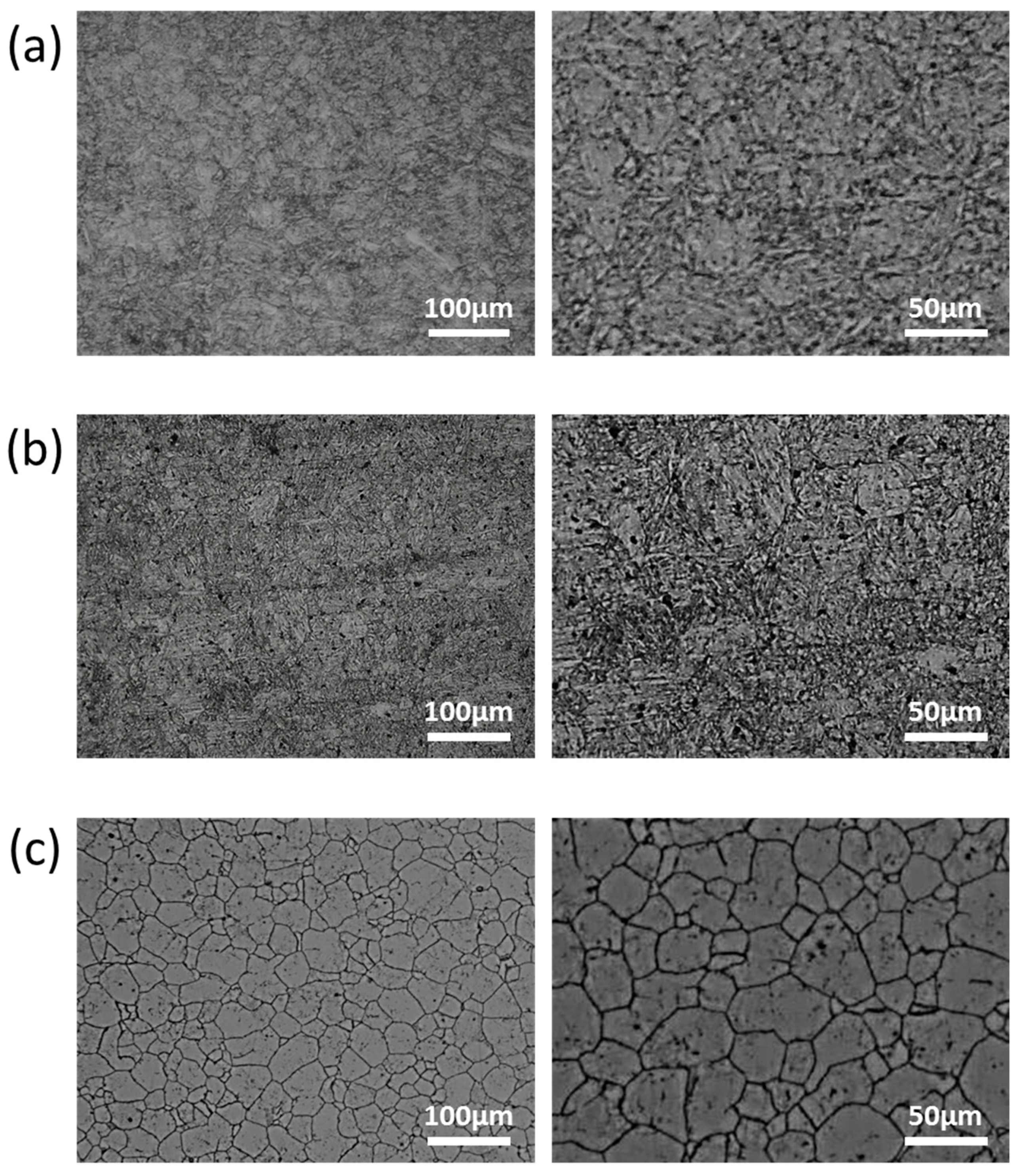
To obtain a detailed microstructure, proper heat treatment procedures and etching techniques were applied, as summarized in Table 2. T91 and HT9 samples were initially normalized at 1050 °C for 1 h and were then air-cooled, tempered at 750 °C for 2 h, and again air-cooled. For SS316L, 1 h solid solution heat treatment at 1050 °C and water quenching were employed to obtain an austenitic structure. The selected alloys were treated with suitable etchants, i.e., Vilella’s reagent (5 mL HCl + 2 g picric acid + 100 mL ethanol) for T91 and HT9 and 5% Nital (5 mL HNO3 + 95 mL ethanol with electrolytic 3 V) for SS316L. Grain sizes were determined in compliance with ASTM E112 through the intercept method. As shown in Figure 3, the prior austenite grain (PAG) sizes of tempered martensitic T91 and HT9 steels were measured as ~30 and ~35 μm, respectively, with that of SS316L being ~25 μm.

2.3. Test Procedures and Specimen Post-Processing

Corrosion tests were performed in static cells by submerging specimens into LBE. Prior to being tested, all specimens were cleansed with acetone and rinsed with deionized water. After corrosion tests, the specimens were removed from static cells and cleansed in a hot glycerin bath at 170 °C to remove the residual LBE on corrosion surfaces.
In order to examine corrosion surfaces, specimens were cut, and their surfaces were refined by minimizing the damage caused to oxide layers on the sample surface or the dissolution morphology/depth. Thus, specimens were first cut by a diamond-bladed low-speed saw at their mid-surface. After the sectioning, the samples were mounted in a suitable mold material, e.g., a mixture of Epo-Thin® and a Ni-based conductive filler. Low-stress wet grinding was performed using diamond suspensions with particle sizes down to 0.05 μm to remove the damage caused by sectioning, replacing large damage with a smaller one (fine scratches). After several stages of wet grinding, samples were mirror-polished with diamond pastes. Between grinding and polishing stages, specimens were cleansed with acetone and ethanol followed by ultrasonic cleaning in deionized water.
The obtained corrosion surfaces of post-processed samples were characterized by optical microscopy, field emission scanning electron microscopy (FE-SEM), and energy dispersive X-ray spectroscopy (EDS) to determine the oxide layer thickness and the structure and chemical composition of the oxide and metal substrates. All the SEM and EDS images shown in this article were consistently taken at an accelerating voltage of 15 kV. In addition, the working distance was varied to obtain clear images, as summarized in Table A4 in Appendix B.

3. Results

3.1. Oxygen Concentration and Temperature Monitoring

Figure 4 shows the results of monitoring oxygen concentration and temperature in LBE during 2000 h corrosion tests at 600 °C. Since the target oxygen concentration in liquid LBE was 10−6 wt.%, the ratio of gas partial pressures, PH2/PH2O, was maintained at 0.1 [42]. LBE temperatures were monitored in both cells. After ~1000 h from the start of the corrosion test, the specimens in cell 1 were removed, and the test conditions of cell 2 were sustained until 2000 h. For most corrosion tests (Figure 4), the temperature and oxygen potential were generally stable, except for short transients due to the following events:
  • Oxygen concentration increase due to excess hydrogen gas;
  • Oxygen concentration decrease due to aeration and decreased temperature;
  • Power blackout;
  • Change of gas cylinders and water tanks in the oxygen control system;
  • End of test.
The above numbering corresponds to the numbers in Figure 4.

3.2. T91

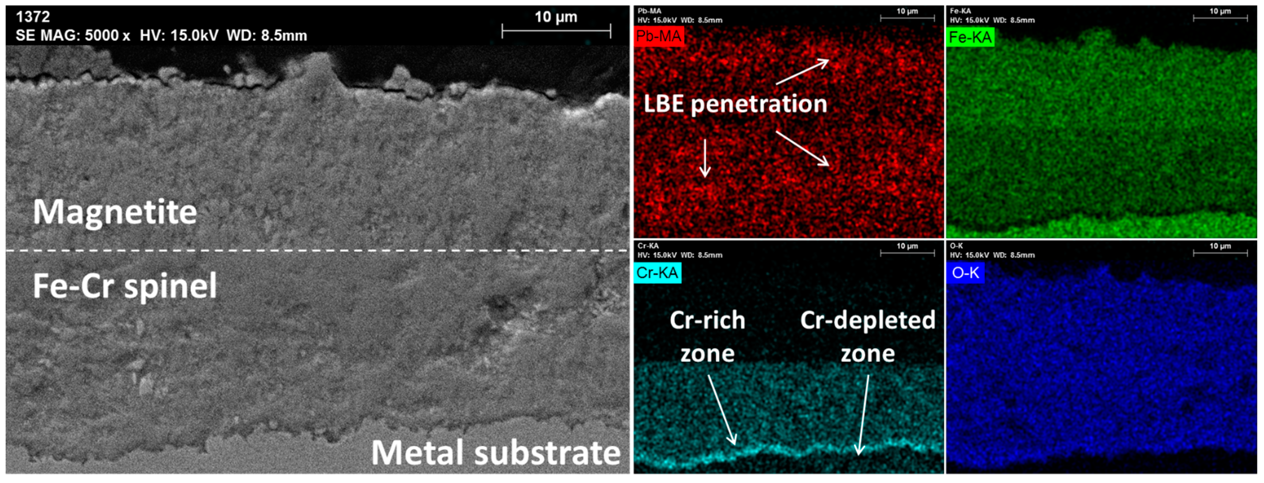
After a 1000 h exposure of T91 to LBE at 600 °C, duplex oxide layers with a total thickness of 45 μm were formed on its surface. Both duplex layer components, namely magnetite on the outside and Fe–Cr spinel inside, had a similar thickness, as shown in Figure 5. A small quantity of LBE penetrated the oxide layers, but the metal substrate was not damaged. A Cr-rich zone was observed at the interface between the Fe–Cr spinel and the metal substrate, while a slightly Cr-depleted zone was found underneath the Cr-rich oxide.
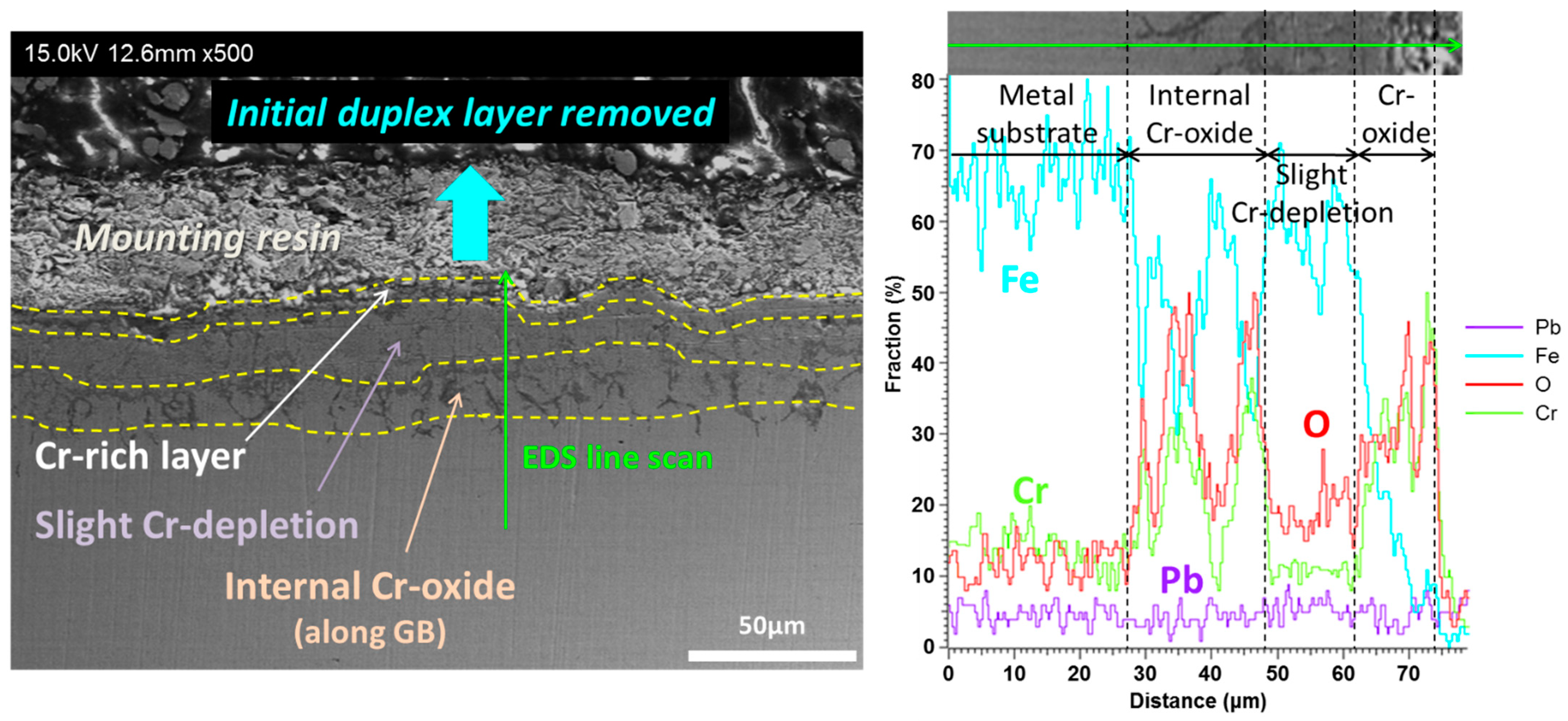
After 2000 h, magnetite and Fe–Cr spinel layers were lost. In some specimens, Cr-rich oxide layers were still found on the metal substrate, as depicted in Figure 6 and Figure 7. Right underneath the Cr-rich oxide, a Cr-depleted zone was observed, similarly to the 1000 h case. Oxygen diffused into the metal substrate boundary, producing the internal Cr-rich oxide along grain boundaries above the Cr-depleted zone. In other specimens, the Cr-rich layer was removed together with the duplex magnetite/Fe–Cr spinel layers. In such cases, LBE penetrated the Cr-depleted zones.

3.3. HT9

The oxide structure of HT9 formed after a 1000 h exposure to LBE at 600 °C was found to be very similar to that of T91. A duplex oxide layer with a thickness of ~25 μm was observed, as shown in Figure 8. No LBE attack to the metal substrate through duplex oxide layers and the Cr-rich oxide zone was detected, and a slightly Cr-depleted zone appeared near the Fe–Cr spinel/metal substrate interface.
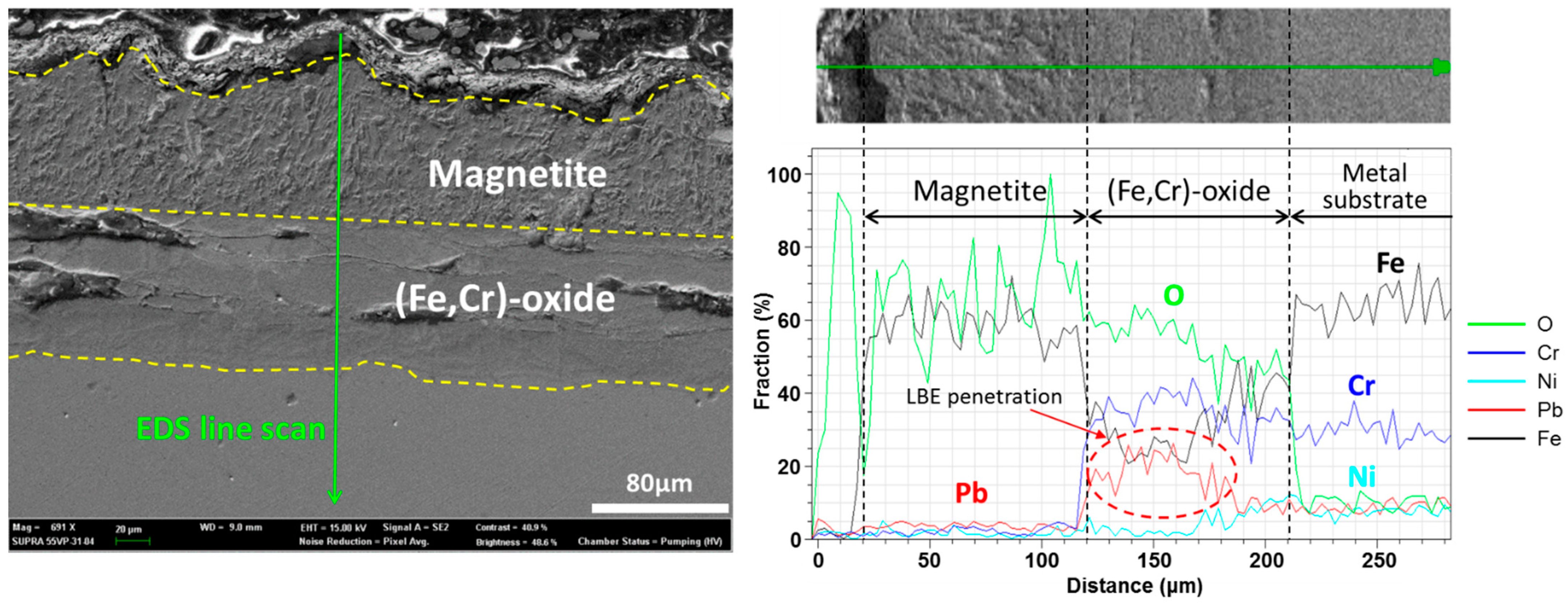
After a 2000 h exposure to liquid LBE, most of the outer magnetite layers were lost, and the Cr rich spinel still remaining in some specimens was directly exposed to LBE, which resulted in LBE penetration along grain boundaries, as shown in Figure 9 and Figure 10. In other specimens, a Cr-depleted region was formed close to the internal Cr–oxide, accelerating LBE penetration. In a severe case presented in Figure 11, LBE deeply penetrated the metal substrate without forming any oxides.

3.4. SS316L

Although SS316L has an austenitic structure, unlike T91 and HT9, its general corrosion morphology and oxide layer structures were found to be nearly identical to those of the above alloys. After a 1000 h exposure of SS316L to LBE at 600 °C, uniform duplex layers were formed on its outer surface, with a Cr-rich spinel layer underneath them. The above duplex layers were ~20 μm thick, being about 50% thinner than those of T91 and HT9. No LBE attack was observed for up to 1000 h.
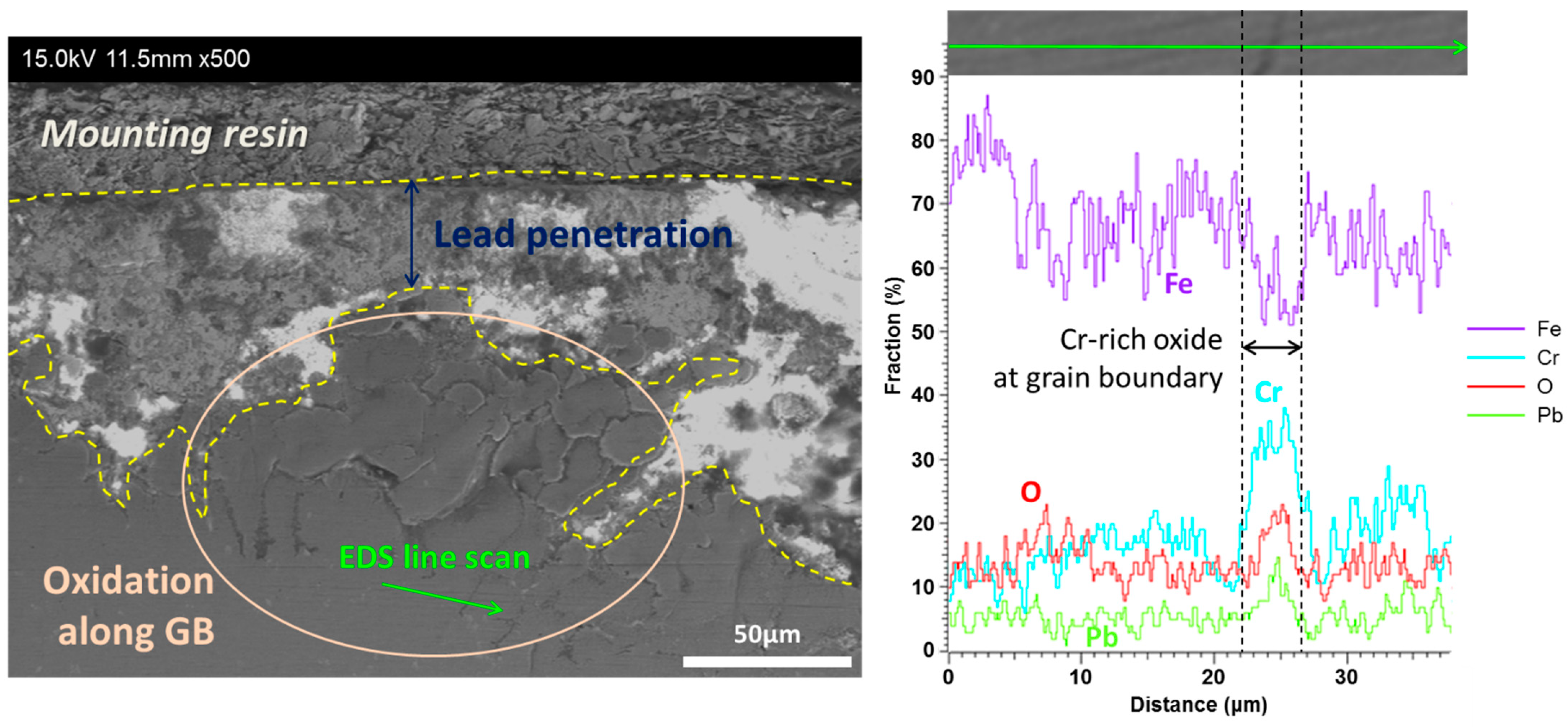
After 2000 h testing, most of the outer magnetite layer was lost. In some specimens, the internal Cr-rich oxide was exposed to LBE, as shown in Figure 12 and Figure 13, with the last figure presenting evidence of LBE penetration. A thin Cr-depleted layer was found between the Cr-rich oxide and the metal substrate. In a severe case, LBE penetrated the metal substrate to a depth of ~300 μm. Some parts of SS316L specimens were lost, decreasing their size, and LBE attack was found to occur at Cr-depleted zones.

4. Discussion

4.1. Corrosion of Cr–Oxide-Forming Alloys in LBE

For up to 1000 h at 600 °C, all tested alloys exhibited a similar evolution of duplex oxide layer structures, regardless of their dissimilar compositions and microstructures. This observation agrees with the results of previous low-temperature studies and reaffirms the similarity of corrosion processes at 600 °C for up to 1000 h: all the materials formed protective single oxide layers at low temperatures while the oxide layer became thicker and changed from a single layer to a duplex layer of magnetite (external) and Fe–Cr spinel (internal) with increasing temperature and test time [16,27,43]. Iron diffused from the metal substrate to the oxide layer, supporting the external magnetite layer growth and producing nanoscale vacancies. Oxygen diffused into specimens via nanochannels and formed the inner Fe–Cr spinel while LBE penetrated the outer magnetite oxide layers, which is very similar what was reported at temperatures below 550 °C [43].
After 2000 h corrosion tests at 600 °C, the duplex oxide layer structure was destroyed in all the specimens, with the oxide layer no longer being protective. This destruction can be rationalized as follows. As the oxide layer grows in thickness, it may be spalled due to excessive lateral compressive stress that leads to tensile stress in the direction perpendicular to the oxide layer [44,45]. Moreover, the stress inside the oxide can increase with its changing composition, since the transition from the metal lattice to the cation lattice of the oxide is accompanied by a volumetric change [44,46,47]. A similar stress build-up has been reported for the Cr/Fe composition change in the oxide layer of Fe–Cr steel [48]. Compressive stress in the transverse direction can induce an upward normal stress [49]. In addition, the cracking of the oxide layer can also be induced by the difference of thermal expansion coefficients of its components, which was ruled out in this experiment by maintaining a constant temperature.
Compared to the case of 1000 h, the oxide layer thickness increases after 2000 h, resulting in weaker layer integrity. After the duplex oxide layers are spalled, they can be re-formed on the bare metal surface exposed to LBE. The thin internal Cr-rich oxide layer grows concomitantly with the Cr-depletion zone due to the selective oxidation of Cr. In some T91 and HT9 specimens, LBE penetrated the Cr-depleted zone. If the above re-passivation fails, as observed for some specimens, the Cr-depleted layer may suffer from LBE penetration due to the significant dissolution of alloying elements after a long exposure to LBE at high temperature. For SS316L, LBE eventually penetrates the metal substrate. Roughly speaking, the maximum thickness of the duplex layer not accompanied by integrity loss has been experimentally determined as 44 ± 6 μm for HT9 and T91, and as 25 ± 6 μm for SS316L.
To sum up, the corrosion process of steels in high-temperature stagnant LBE advances through several steps. Firstly, a single oxide layer of Fe–Cr spinel forms on the interface between LBE and substrate metal, which is protective against LBE penetration. As exposure time elapses, the oxide structure grows further and become a duplex structure where magnetite builds up on the interface between LBE above the Fe–Cr spinel layer. The growth of the oxide layer exerts a higher compressive stress to the duplex layer, which leads to the oxide being spalled. This removal allows LBE to penetrate into the outer layer of magnetite and then even into the spinel layer. Due to the selective oxidation given by Cr diffusion in the metal substrate, a Cr-depleted layer forms near the inner interface between the spinel and substrate. This re-passivation also contributes to the prevention of further LBE penetration. However, the more the oxidation layer grows, the higher the stress is given to the layer and finally some of it can be spalled as seen in the duplex layer. This local failure of the Cr–oxide layer allows LBE to penetrate. The condition is maintained, while the re-passivation and local oxide removal occur iteratively, and LBE penetrates deeply through the metal substrate.

4.2. Oxygen Concentration Control in LBE

An YSZ oxygen sensor was used to control the oxygen concentration in LBE, mainly utilizing redox reactions described as a (Bi/Bi2O3)|YSZ|(LBE/LBE·O) galvanic cell [41]. The YSZ membrane acted as a solid electrolyte and an oxygen ion conductor, while Bi/Bi2O3 functioned as a reference couple located inside the YSZ tube. The electromotive force (EMF) signal was generated by the metal/oxide reference determined by the oxygen concentration in LBE and was transmitted via a Mo wire inserted into the YSZ tube. The above oxygen sensor was calibrated using electrochemical impedance spectroscopy (EIS) to overcome its disadvantage of signal hysteresis upon heating and cooling and to achieve reproducibility between measurements, as described in Ref. [41].
Based on EMF measurements during corrosion tests, each signal could be converted to oxygen concentration with a measured LBE bulk temperature. The activity of oxygen dissolved in LBE, aO, can be expressed as
a O = C O C s , O ,
where CO is the concentration of oxygen, and Cs,O is the solubility of oxygen in LBE, both in wt.%. The following simple relation has been reported [50]:
log C s , O = 1.2 3400 T ( 673 973   K ) .
According to the Nernst equation, the EMF across the YSZ membrane acting as a solid electrolyte is directly related to oxygen potential [51]:
log a O = 10079 T ( E 0.1381 ) 0.7173 ,
where T is the bulk LBE temperature in K and E the measured EMF in V, respectively. By combining Equation (1) with Equations (2) and (3), the expression for oxygen concentration is obtained as
log C O = log a O + log C s , O = 0.4872 10079 T ( E + 0.1992 ) .
The concentration of oxygen determined using Equation (4) is shown in Figure 4.
PbO precipitation occurs at oxygen concentrations above ~1 × 10⁻³ wt.%, and iron oxides start to decompose at oxygen levels below 2 × 10⁻⁸ wt.% at 600 °C, as shown in Figure 14 which illustrates the upper and lower boundaries of dissolved oxygen control as the oxygen solubility and magnetite formation limit, respectively, even though the reported solubility of oxygen in LBE is subject to variation [50,52]. Therefore, corrosion tests had to be carried out at an oxygen level of ~1 × 10⁻⁶ wt.%, at which magnetite and Fe–Cr spinel are stable. In other words, specimens were exposed to oxide-forming and oxide-growing environments, while the oxide layer growth rates differed among the three alloys.
Notably, the oxygen concentration remained stable during testing, except for several transients attributed to external causes as mentioned in Section 3.1. In the stable region, the oxygen concentration varied from 1 × 10⁻⁶ to 3 × 10⁻⁶ wt.%, as intended. However, several events due to external causes were observed, with oxygen levels being outside the controlled range. After the start of corrosion tests, the concentration of oxygen in LBE seemed to be lower than that required for the onset of magnetite formation, as described by No. 1 in Figure 4, which was attributed to excess hydrogen gas. Even though the oxygen concentration decreased at an early stage, magnetite and Fe–Cr spinel were in a stable region, considering that the oxide layer thickness showed similarity to previously reported trends.
Subsequently, aeration occurred, as indicated by No. 2 in Figure 4. As the oxide layer growth was hindered, passivation was accelerated by the increased oxygen partial pressure, leading to a steep rise in oxygen concentration. The maximum oxygen concentration (1 × 10⁻⁴ wt.%) was lower than that required for PbO formation and declined in a few hours. Several hours after this peak, the duplex layer growth could be sustained. This process still holds for event No. 4, i.e., gas cylinder and water tank replacement, as illustrated in Figure 4.
A new rapid decrease in the amount of oxygen dissolved in LBE was caused by an unexpected power blackout, as indicated by event No. 3 in Figure 4, in less than four hours. Its difference from event No. 1 is that it was prompted by a temperature drop due to a heater outage, while No. 1 was caused by a chemical condition change in the cover gas. As the temperature dropped, oxide growth could be suppressed, being an exothermic reaction, and the chemical equilibrium can be shifted to its side, even though the significant oxygen concentration drop can affect the 2000 h test results. Therefore, this event does not seem to directly influence oxide structure deterioration. In addition, re-passivation could be hindered if the duplex layer had already been destroyed by this event.

4.3. Prediction of Oxide Layer Thickness in High-Temperature LBE

The thicknesses of oxide layers can be predicted by the parabolic oxidation law [53]. The experimental values obtained for T91, HT9, and SS316L in this study at 1000 h, together with abundant literature values [15,18,54,55,56,57,58,59,60,61,62,63,64,65,66,67], are plotted against temperature in Figure 15, Figure 16 and Figure 17. The data points plotted in the figures can be found in Table A1, Table A2 and Table A3 in Appendix A.
For T91, the predicted values showed good agreement with previous experimental results at temperatures below 500 °C, while large deviations were observed above 535 °C. For HT9, the parabolic law was valid below 500 °C, with the corresponding rate constant being almost equal to that of T91. For SS316L, a thin Fe–Cr spinel layer was formed at temperatures below ~450 °C, while duplex layers were observed at higher temperature. Dissolution started at ~500–550 °C, and experimental results were consistent with predictions for T91 and HT9 at temperatures below the dissolution onset.
As the corrosion tests in this study were carried out in static cells, the results cannot be correlated or extrapolated to the corrosion behavior under LBE-flowing conditions as there is an additional stress given as shear by the flow at the interface between the LBE and oxide layer, in addition to the stress given by oxide growth. Additionally, a system with a non-uniform temperature distribution along the flow path also differs from the static condition, since temperature dependence in solubility influences the spalling of an oxide layer. Once the dissolution of alloying elements occurs at a hotter region, it leads to a continuous mass transfer to a colder zone since no local equilibrium can be met. Moreover, the colder zone may undergo a flow area blockage from the reduction in solubility, which results in the precipitation of the transported material.

5. Conclusions

The corrosive nature of lead and LBE at high temperatures on structural materials has been highlighted a major challenge for LFRs in the near future. To cope with it, this study aimed to identify the corrosion behaviors of selected ASME code-certified materials, namely ferritic/martensitic stainless steels (T91 and HT9) and austenitic stainless steels (SS316L). The corresponding tests were performed for 2000 h in static LBE-containing cells at 600 °C at a dissolved oxygen concentration of 10−6 wt.%. The obtained results not only reaffirm previous data on duplex oxide layer evolution for up to 1000 h but also indicate the oxide layer spalls as a result of compressive stress given by oxide build-up as time elapses, which leads to a repeating cycle of LBE penetration and local re-passivation. The produced duplex layers consisted of magnetite and Fe–Cr spinel for all three steel alloys, which were found to be destroyed after 2000 h testing. For T91 and HT9, a thin internal Cr-rich protective layer was formed, but LBE penetrated into the Cr-depleted zone underneath this layer in some specimens. Severe dissolution was observed for SS316L, and LBE penetrated the metal substrate to a depth of up to ~300 μm. Some events during testing changed the concentration of oxygen, which were only temporary. Additionally, the concentration of oxygen was maintained within the oxide stability range. Comparative data analysis showed that the growth of oxide layers on HT9 and T91 is well predicted by the parabolic law up to 450 °C, with more stable protective layers based on Al– or Si-–oxides required above this temperature. As the corrosion tests were conducted within the static conditions, the results cannot be directly extrapolated to conditions under a flow field.

Author Contributions

Conceptualization, S.G.L. and I.S.H.; methodology, S.G.L.; validation, S.G.L., Y.-H.S. and J.P.; formal analysis, S.G.L. and Y.-H.S.; investigation, S.G.L.; resources, S.G.L.; data curation, S.G.L., Y.-H.S. and J.P.; writing—original draft preparation, S.G.L. and Y.-H.S.; writing—review and editing, Y.-H.S., J.P. and I.S.H.; visualization, S.G.L. and Y.-H.S.; supervision, J.P. and I.S.H.; project administration, I.S.H.; funding acquisition, J.P. and I.S.H. All authors have read and agreed to the published version of the manuscript.

Funding

This work was supported by a National Research Foundation of Korea (NRF) grant funded by the Ministry of Science and ICT, Republic of Korea (NRF-2021M2D1A1019061).

Institutional Review Board Statement

Not applicable.

Informed Consent Statement

Not applicable.

Data Availability Statement

Not applicable.

Conflicts of Interest

The authors declare no conflict of interest.

Appendix A

The datasets from open literature [15,18,54,55,56,57,59,60,61,62,63,65,66,67] plotted in Figure 15, Figure 16 and Figure 17 are summarized in Table A1, Table A2 and Table A3, respectively. In all the tables, the exposure times and corrosion depths of specimens are given in pairs, namely in a format of (time, corrosion depth).
Table A1. Data points plotted in Figure 15 [15,54,55,59,60,65,66].
Temperature (°C)Reference(Time (h), Corrosion Depth (μm))
350[60](1000, 2)
[65](1500, 6)(3000, 6)
450[60](550, 10)(1000, 12)(2000, −3)
[59](3000, 12)(3000, 30)
[54](500, 6)(1500, 5)
470[15](1116, 11)(2000, 14)(3116, 16)
[55](2300, 16)(3800, 19)(4500, 24)(6300, 25)(7800, 30)
535[66](500, 18)(3000, −26)
550[60](550, −7)(550, 7)(1000, 12)(2000, −30)
[66](500, 17)(3000, −34)(3000, −20)
600[60](550, 14)(1000, 4)
[66](500, −21)(3000, −130)
[54](100, 10)(100, 20)(100, 22)(500, 5)(500, 32)
(500, 41)(1500, −13)(1500, −10)(1500, 40)(1500, 95)
This study(1000, 45)
Table A2. Data points plotted in Figure 16 [18,56,67].
Temperature (°C)Reference(Time (h), Corrosion Depth (μm))
450[18](200, 4.2)(500, 6.1)
460[56](2000, 13)(3000, 15)
500[18](500, 12)(1000, 17)
[67](800, 8)(5000, 65)
550[67](5000, 50)
600This study(1000, 25)
Table A3. Data points plotted in Figure 17 [54,56,57,59,60,61,62,63,65,66,67].
Temperature (°C)Reference(Time (h), Corrosion Depth (μm))
400[65](3000, 1)
[62](5000, 1)
450[63](3000, 23)
[60](550, 3)(1000, 3)
[59](3000, 4)
[57](3000, 2.58)
[54](2400, −25)
460[56](2000, 3)(3000, 4)
476[62](1200, 3)
500[67](800, 6)(2000, 6)(5000, 6)(10000, −40)
535[66](500, 11)(3000, −60)
550[61](800, 10)(2000, 20)
[60](550, −50)(550, 7)(1000, 8)
[57](3000, −22.41)(500, 9)(3000, −70)(3000, −46)
[66](100, −9)
[67](800, 15)(2000, 15)(5000, 15)(10000, −200)
600[60](550, 20)(1000, 20)
[66](500, −55)(3000, −156)
[67](800, −15)(2000, −20)(5000, −20)(10000, −180)
[54](100, 0.3)(100, 8)(100, 20)(500, −40)(500, 24)
(500, 27)(1500, −83)(1500, −63)(1500, 15)(1500, 45)
This study(1000, 20)

Appendix B

The operating parameters for SEM and EDS images shown in this article are summed up in Table A4.
Table A4. SEM/EDS operating parameters in this study.
FigureAccelerating Voltage (kV)Working Distance (mm)
Figure 5158.5
Figure 68.5
Figure 712.6
Figure 88.5
Figure 911.5
Figure 107.2
Figure 118.5
Figure 129.0
Figure 138.8

References

  1. Gromov, B.F. Use of lead-bismuth coolant in nuclear reactors and accerlerator-driven systmes. Nucl. Eng. Des. 1997, 173, 207–217. [Google Scholar] [CrossRef]
  2. Toshinsky, G.; Grigoriev, O.; Efimov, E.; Leonchuk, M.; Novikova, N.; Pankratov, D.; Skorikov, D.; Klimov, N.; Stepanov, V. Safety aspects of SVBR-75/100 reactor. In Proceedings of the Advanced Nuclear Reactor Safety Issues and Research Needs, Paris, France, 18–20 February 2002; pp. 71–86. [Google Scholar]
  3. Abderrahim, H.A.; Kupschus, P.; Malambu, E.; Benoit, P.; Van Tichelen, K.; Arien, B.; Vermeersch, F.; D’hondt, P.; Jongen, Y.; Ternier, S.; et al. MYRRHA: A multipurpose accelerator driven system for research & development. Nucl. Instrum. Methods Phys. Res. Sect. A 2001, 463, 487–494. [Google Scholar]
  4. Hwang, I.S.; Jeong, S.H.; Park, B.G.; Yang, W.S.; Suh, K.Y.; Kim, C.H. The concept of proliferation-resistant, environment-friendly, accident-tolerant, continual and economical reactor (PEACER). Prog. Nucl. Energy 2000, 37, 217–222. [Google Scholar] [CrossRef]
  5. Sekimoto, H.; Ryu, K.; Yoshimura, Y. CANDLE: The new burnup strategy. Nucl. Sci. Eng. 2001, 139, 306–317. [Google Scholar] [CrossRef]
  6. Stanisz, P.; Oettingen, M.; Cetnar, J. Monte Carlo modeling of Lead-Cooled Fast Reactor in adiabatic equilibrium state. Nucl. Eng. Des. 2016, 301, 341–352. [Google Scholar] [CrossRef]
  7. Choi, S.; Cho, J.-H.; Bae, M.-H.; Lim, J.; Puspitarini, D.; Jeun, J.H.; Joo, H.-G.; Hwang, I.S. PASCAR: Long burning small modular reactor based on natural circulation. Nucl. Eng. Des. 2011, 241, 1486–1499. [Google Scholar] [CrossRef]
  8. Shin, Y.-H.; Choi, S.; Cho, J.; Kim, J.H.; Hwang, I.S. Advanced passive design of small modular reactor cooled by heavy liquid metal natural circulation. Prog. Nucl. Energy 2015, 83, 433–442. [Google Scholar] [CrossRef]
  9. Sienicki, J.J.; Spencer, B.W. Power optimization in the STAR-LM modular natural convection reactor system. In Proceedings of the 10th International Conference on Nuclear Engineering, Arlington, VA, USA, 14–18 April 2002. [Google Scholar]
  10. Wade, D.; Feldman, E.; Sienicki, J.; Sofu, T.; Barak, A.; Greenspan, E.; Saphier, D.; Brown, N.; Hossain, Q.; Carelli, M. ENHS: The encapsulated nuclear heat source—A nuclear energy concept for emerging worldwide energy markets. In Proceedings of the 10th International Conference on Nuclear Engineering, Arlington, VA, USA, 14–18 April 2002. [Google Scholar]
  11. Generation IV International Forum. Technology Roadmap Update for Generation IV Nuclear Energy Systems; OECD Nuclear Energy Agency: Paris, France, 2014. [Google Scholar]
  12. Li, N. Lead-alloy coolant technology and materials. Prog. Nucl. Energy 2007, 50, 140–151. [Google Scholar] [CrossRef]
  13. Allen, T.R.; Crawford, D.C. Lead-Cooled Fast Reactor Systems and the Fuels and Materials Challenges. Sci. Technol. Nucl. Install. 2007, 2007, 097486. [Google Scholar]
  14. OECD/NEA. Handbook on Lead-Bismuth Eutectic Alloy and Lead Properties, Materials Compatibility, Thermal-Hydraulics and Technologies, 2015 edition; Organisation for Economic Co-Operation and Development: Paris, France, 2015. [Google Scholar]
  15. Barbier, F.; Rusanov, A. Corrosion behavior of steels in flowing lead–bismuth. J. Nucl. Mater. 2001, 296, 231–236. [Google Scholar] [CrossRef]
  16. Müller, G.; Schumacher, G.; Zimmermann, F. Investigation on oxygen controlled liquid lead corrosion of surface treated steels. J. Nucl. Mater. 2000, 278, 85–95. [Google Scholar] [CrossRef]
  17. Weisenburger, A.; Heinzel, A.; Müller, G.; Muscher, H.; Rousanov, A. T91 cladding tubes with and without modified FeCrAlY coatings exposed in LBE at different flow, stress and temperature conditions. J. Nucl. Mater. 2008, 376, 274–281. [Google Scholar] [CrossRef]
  18. Lim, J.; Nam, H.O.; Hwang, I.S.; Kim, J.H. A study of early corrosion behaviors of FeCrAl alloys in liquid lead–bismuth eutectic environments. J. Nucl. Mater. 2010, 407, 205–210. [Google Scholar] [CrossRef]
  19. Lim, J.; Hwang, I.S.; Kim, J.H. Design of alumina forming FeCrAl steels for lead or lead–bismuth cooled fast reactors. J. Nucl. Mater. 2013, 441, 650–660. [Google Scholar] [CrossRef]
  20. Dvoriashin, A.M.; Porollo, S.I.; Konobeev, Y.V.; Budylkin, N.I.; Mironova, E.G.; Ioltukhovskiy, A.G.; Leontyeva-Smirnova, M.V.; Garner, F.A. Mechanical properties and microstructure of three Russian ferritic/martensitic steels irradiated in BN-350 reactor to 50 dpa at 490 °C. J. Nucl. Mater. 2007, 367–370, 92–96. [Google Scholar] [CrossRef]
  21. Wang, J.; Lu, S.; Rong, L.; Li, D.; Li, Y. Effect of silicon on the oxidation resistance of 9 wt. % Cr heat resistance steels in 550 °C lead-bismuth eutectic. Corros. Sci. 2016, 111, 13–25. [Google Scholar]
  22. García Ferré, F.; Ormellese, M.; Di Fonzo, F.; Beghi, M.G. Advanced Al2O3 coatings for high temperature operation of steels in heavy liquid metals: a preliminary study. Corros. Sci. 2013, 77, 375–378. [Google Scholar] [CrossRef]
  23. Ballinger, R.G.; Lim, J. An overview of corrosion issues for the design and operation of high-temperature lead-and lead-bismuth-cooled reactor systems. Nucl. Technol. 2004, 147, 418–435. [Google Scholar] [CrossRef]
  24. Shankar Rao, V.; Lim, J.; Soon Hwang, I.L. Analysis of 316L stainless steel pipe of lead–bismuth eutectic cooled thermo-hydraulic loop. Ann. Nucl. Energy 2012, 48, 40–44. [Google Scholar] [CrossRef]
  25. Schroer, C.; Wedemeyer, O.; Skrypnik, A.; Novotny, J.; Konys, J. Corrosion kinetics of Steel T91 in flowing oxygen-containing lead–bismuth eutectic at 450 °C. J. Nucl. Mater. 2012, 431, 105–112. [Google Scholar] [CrossRef]
  26. Kurata, Y. Corrosion behavior of cold-worked austenitic stainless steels in liquid lead–bismuth eutectic. J. Nucl. Mater. 2014, 448, 239–249. [Google Scholar] [CrossRef]
  27. Zhang, J.; Li, N.; Chen, Y.; Rusanov, A.E. Corrosion behaviors of US steels in flowing lead–bismuth eutectic (LBE). J. Nucl. Mater. 2005, 336, 1–10. [Google Scholar] [CrossRef]
  28. Heinzel, A.; Weisenburger, A.; Müller, G. Corrosion behavior of austenitic steels in liquid lead bismuth containing 10−6 wt% and 10−8 wt% oxygen at 400–500 °C. J. Nucl. Mater. 2014, 448, 163–171. [Google Scholar] [CrossRef]
  29. Martín-Muñoz, F.J.; Soler-Crespo, L.; Gómez-Briceño, D. Corrosion behaviour of martensitic and austenitic steels in flowing lead–bismuth eutectic. J. Nucl. Mater. s 2011, 416, 87–93. [Google Scholar] [CrossRef]
  30. Doubková, A.; Di Gabriele, F.; Brabec, P.; Keilová, E. Corrosion behavior of steels in flowing lead–bismuth under abnormal conditions. J. Nucl. Mater. 2008, 376, 260–264. [Google Scholar] [CrossRef]
  31. Schroer, C.; Wedemeyer, O.; Novotny, J.; Skrypnik, A.; Konys, J. Selective leaching of nickel and chromium from Type 316 austenitic steel in oxygen-containing lead–bismuth eutectic (LBE). Corros. Sci. 2014, 84, 113–124. [Google Scholar] [CrossRef] [Green Version]
  32. Schroer, C.; Skrypnik, A.; Wedemeyer, O.; Konys, J. Oxidation and dissolution of iron in flowing lead–bismuth eutectic at 450 °C. Corros. Sci. 2012, 61, 63–71. [Google Scholar] [CrossRef]
  33. Hadjem-Hamouche, Z.; Auger, T.; Guillot, I. Temperature effect in the maximum propagation rate of a liquid metal filled crack: The T91 martensitic steel/Lead–Bismuth Eutectic system. Corros. Sci. 2009, 51, 2580–2587. [Google Scholar] [CrossRef]
  34. Yamaki, E.; Ginestar, K.; Martinelli, L. Dissolution mechanism of 316L in lead–bismuth eutectic at 500 °C. Corros. Sci. 2011, 53, 3075–3085. [Google Scholar] [CrossRef]
  35. Klueh, R.L.; Nelson, A.T. Ferritic/martensitic steels for next-generation reactors. J. Nucl. Mater. 2007, 371, 37–52. [Google Scholar] [CrossRef]
  36. Garner, F.A.; Toloczko, M.B.; Sencer, B.H. Comparison of swelling and irradiation creep behavior of fcc-austenitic and bcc-ferritic/martensitic alloys at high neutron exposure. J. Nucl. Mater. 2000, 276, 123–142. [Google Scholar] [CrossRef]
  37. Schroer, C.; Wedemeyer, O.; Novotny, J.; Skrypnik, A.; Konys, J. Performance of 9% Cr steels in flowing lead-bismuth eutectic at 450 and 550 °C, and 10−6 mass% dissolved oxygen. Nucl. Eng. Des. 2014, 280, 661–672. [Google Scholar] [CrossRef]
  38. Schroer, C.; Koch, V.; Wedemeyer, O.; Skrypnik, A.; Konys, J. Silicon-containing ferritic/martensitic steel after exposure to oxygen-containing flowing lead–bismuth eutectic at 450 and 550 °C. J. Nucl. Mater. 2016, 469, 162–176. [Google Scholar] [CrossRef]
  39. Kurata, Y.; Futakawa, M.; Saito, S. Corrosion behavior of steels in liquid lead–bismuth with low oxygen concentrations. J. Nucl. Mater. 2008, 373, 164–178. [Google Scholar] [CrossRef]
  40. Kurata, Y. Corrosion behavior of Si-enriched steels for nuclear applications in liquid lead–bismuth. J. Nucl. Mater. 2013, 437, 401–408. [Google Scholar] [CrossRef]
  41. Nam, H.O.; Lim, J.; Han, D.Y.; Hwang, I.S. Dissolved oxygen control and monitoring implementation in the liquid lead-bismuth eutectic loop: HELIOS. J. Nucl. Mater. 2008, 376, 381. [Google Scholar] [CrossRef]
  42. Weisenburger, A. Corrosion in HLM systems. In Proceedings of the International Workshop on Innovative Nuclear Reactors Cooled by Heavy Liquid Metals: Status and Prospectives, Pisa, Italy, 17–20 April 2012. [Google Scholar]
  43. Martinelli, L.; Balbaud-Célérier, F. Modelling of the oxide scale formation on Fe-Cr steel during exposure in liquid lead-bismuth eutectic in the 450–600° C temperature range. Mater. Corros. 2011, 62, 531–542. [Google Scholar] [CrossRef]
  44. Pilling, N.B.; Bedworth, R.E. The oxidation of metals at high temperatures. Journal of the Institute of Metals 1923, 29, 529–582. [Google Scholar]
  45. Birks, N.; Meier, G.H.; Pettit, F.S. Introduction to the High Temperature Oxidation of Metals; Cambridge University Press: Cambridge, UK, 2006. [Google Scholar]
  46. Appleby, W.; Tylecote, R. Stresses during the gaseous oxidation of metals. Corros. Sci. 1970, 10, 325–341. [Google Scholar] [CrossRef]
  47. Wood, G.C.; Stott, F.H. Oxidation of alloys. Mater. Sci. Technol. 1987, 3, 519–530. [Google Scholar] [CrossRef]
  48. Howes, V.; Richardson, C. The initial stresses developed during high temperature oxidation of Fe-Cr alloys. Corros. Sci. 1969, 9, 385–394. [Google Scholar] [CrossRef]
  49. Betz, W.; Brunetaud, R.; Coutsourais, D.; Fischmeister, H.; Gibbons, T.B.; Kvernes, I.; Lindblom, Y.; Marriott, J.B.; Meadowcroft, D.B. High Temperature Alloys for Gas Turbines and Other Applications; D. Reidel Publishing Company: Dordrecht, The Netherlands, 1987. [Google Scholar]
  50. Martynov, P.N.; Ivanov, K.D. Properties of Lead-Bismuth Coolant and Perspectives of Non-Electric Applications of Lead-Bismuth Reactor; Technical Report; IAEA: Vienna, Austria, 1997. [Google Scholar]
  51. Li, N.; Hang, W.; Darling, T. Oxygen sensor calibration for LBE coolant chemistry control. In Proceedings of the 11th International Conference on Nuclear Engineering (ICONE-11), Tokyo, Japan, 20–23 April 2003. [Google Scholar]
  52. Müller, G.; Heinzel, A.; Schumacher, G.; Weisenburger, A. Control of oxygen concentration in liquid lead and lead–bismuth. J. Nucl. Mater. 2003, 321, 256–262. [Google Scholar] [CrossRef]
  53. Wagner, C. Theoretical analysis of the diffusion processes determining the oxidation rate of alloys. J. Electrochem. Soc. 1952, 99, 369. [Google Scholar] [CrossRef]
  54. Soler, L.; Martín, F.J.; Hernandez, F.; Gomez-Briceno, D. Corrosion of Stainless Steels in Lead-bismuth Eutectic up to 600°C. J. Nucl. Mater. 2004, 335, 174. [Google Scholar] [CrossRef]
  55. Martinelli, L.; Balbaud-Celerier, F.; Bosonnet, S.; Terlain, A.; Santarini, G.; Delpech, S.; Picard, G. High Temperature Oxidation of Fe-9Cr Steel in Stagnant Liquid Lead-bismuth. Trans. Am. Nucl. Soc. 2008, 98, 1136–1137. [Google Scholar]
  56. Li, N.; He, X.; Rusanov, A.; Demishonkov, A.P. Corrosion Tests of US Steels in Lead-Bismuth Eutectic (LBE) and Kinetic Modelling of Corrosion in LBE Systems; LA-UR-01-5241; Los Alamos National Laboratory: Los Alamos, NM, USA, 2001. [Google Scholar]
  57. Kurata, Y.; Futakawa, M.; Saito, S. Comparison of the Corrosion Behavior of Austenitic and Ferritic/Martensitic Steels Exposed to Static Liquid Pb-Bi at 450 and 550C. J. Nucl. Mater. 2005, 343, 335. [Google Scholar] [CrossRef]
  58. Kondo, M.; Takahashi, M.; Suzuki, T.; Ishikawa, K.; Hata, K.; Qiu, S.; Sekimoto, H. Metallurgical Study on Erosion and Corrosion Behaviors of Steels Exposed to Liquid Lead-bismuth Flow. J. Nucl. Mater. 2005, 343, 349. [Google Scholar] [CrossRef]
  59. Gomez-Briceno, D.; Crespo, L.S.; Munoz, F.J.M.; Hernández, F. Oxide Formation Efficiency in Stagnant Lead-Bismuth; CIEMAT: Madrid, Spain, 2004. [Google Scholar]
  60. Gnecco, F.; Ricci, E.; Bottino, C.; Passerone, A. Corrosion Behaviour of Steels in Lead-bismuth at 823 K. J. Nucl. Mater. 2004, 335, 185. [Google Scholar] [CrossRef]
  61. Furukawa, T.; Müller, G.; Schumacher, G.; Weisenburger, A.; Heinzel, A.; Aoto, K. Effect of Oxygen Concentration and Temperature on Compatibility of ODS Steel with Liquid, Stagnant Pb45Bi55. J. Nucl. Mater. 2004, 335, 189. [Google Scholar] [CrossRef]
  62. Fazio, C.; Benamati, G.; Martini, C.; Palombarini, G. Compatibility Tests on Steels in Molten Lead and Lead-bismut. J. Nucl. Mater. 2001, 296, 243. [Google Scholar] [CrossRef]
  63. Deloffre, P.; Terlain, A.; Barbier, F. Corrosion and Deposition of Ferrous Alloys in Molten Lead-bismuth. J. Nucl. Mater. 2002, 301, 35. [Google Scholar] [CrossRef]
  64. Benamati, G.; Fazio, C.; Piankova, H.; Rusanov, A. Temperature Effect on the Corrosion Mechanism of Austenitic and Martensitic Steels in Lead-bismuth. J. Nucl. Mater. 2002, 301, 23. [Google Scholar] [CrossRef]
  65. Aiello, A.; Azzati, M.; Benamati, G.; Gessi, A.; Long, B.; Scaddozzo, G. Corrosion Behaviour of Stainless Steels in Flowing LBE at Low and High Oxygen Concentration. J. Nucl. Mater. 2004, 335, 169. [Google Scholar] [CrossRef]
  66. Martın, F.; Soler, L.; Hernandez, F.; Gomez-Briceno, D. Oxide layer stability in lead–bismuth at high temperature. J. Nucl. Mater. 2004, 335, 194–198. [Google Scholar] [CrossRef]
  67. Müller, G.; Heinzel, A.; Konys, J.; Schumacher, G.; Weisenburger, A.; Zimmermann, F.; Engelko, V.; Rusanov, A.; Markov, V. Behavior of steels in flowing liquid PbBi eutectic alloy at 420–600 C after 4000–7200 h. J. Nucl. Mater. 2004, 335, 163–168. [Google Scholar] [CrossRef]
Figure 1. (a) Schematic diagram and (b) picture of a static lead–bismuth eutectic (LBE) corrosion cell.
Applsci 11 02349 g001
Figure 2. (a) Schematic diagram and (b) picture of a corrosion specimen.
Applsci 11 02349 g002
Figure 3. Microstructure of (a) T91, (b) HT9, and (c) SS316L before exposure to LBE. Left: 20× magnification, right: 80× magnification.
Applsci 11 02349 g003
Figure 4. History of LBE temperature and oxygen potential/concentration in a static cell during corrosion tests at 600 °C.
Applsci 11 02349 g004
Figure 5. Passive duplex oxide layers formed on T91 after 1000 h at 600 °C.
Applsci 11 02349 g005
Figure 6. Cr-rich spinel layer and a slightly Cr-depleted region on T91 after 2000 h at 600 °C.
Applsci 11 02349 g006
Figure 7. EDS analysis of Cr-rich layer, Cr-depleted zone, and internal Cr oxide along the grain boundaries of T91 after 2000 h at 600 °C.
Applsci 11 02349 g007
Figure 8. Stable duplex oxide layers on HT9 after 1000 h at 600 °C.
Applsci 11 02349 g008
Figure 9. EDS analysis of the HT9 metal substrate close to the severely LBE-penetrated region after 2000 h at 600 °C.
Applsci 11 02349 g009
Figure 10. EDS analysis of the LBE-penetrated regions on HT9 for Cr-depleted and inner Cr-rich reformed oxide regions after 2000 h at 600 °C.
Applsci 11 02349 g010
Figure 11. Severe LBE penetration on HT9 without oxide formation after 2000 h at 600 °C.
Applsci 11 02349 g011
Figure 12. Stable duplex oxide layers on SS316L after 1000 h at 600 °C.
Applsci 11 02349 g012
Figure 13. EDS analysis of LBE-penetrated region on SS316L in Cr-depleted and inner Cr-rich reformed oxide regions after 2000 h at 600 °C.
Applsci 11 02349 g013
Figure 14. Stable oxygen control range in LBE as a function of LBE temperature [50,52].
Applsci 11 02349 g014
Figure 15. Prediction of the corrosion depths on T91 [15,53,54,55,59,60,65,66].
Applsci 11 02349 g015
Figure 16. Prediction of the corrosion depths on HT9 [18,53,56,67].
Applsci 11 02349 g016
Figure 17. Prediction of the corrosion depths on SS316L [53,54,56,57,59,60,61,62,63,65,66,67].
Applsci 11 02349 g017
Table 1. Elemental compositions of tested materials (in wt.%).
Main ElementsFeCrNiMoMnSiWNbVC
T91NominalBal.8.50.210.50.3-0.060.20.1
MeasuredBal.8.610.180.960.450.229-0.070.220.09
HT9NominalBal.11.50.510.60.40.5-0.30.1
MeasuredBal.11.630.501.030.550.360.52-0.280.11
SS316LNominalBal.17.010.02.20.90.4---0.02
MeasuredBal.16.8710.312.070.920.44---0.021
Table 2. Heat treatment and etching conditions of tested materials.
MaterialsHeat Treatment ProcedureEtchant
T91, HT91. Normalization (1050 °C, 1 h) and air-cooling
2. Tempering (750 °C, 2 h) and air-cooling
Vilella’s reagent (5 mL HCl + 2 g picric acid + 100 mL ethanol)
SS316LSolid solution heat treatment (1050 °C, 1 h) and water-quenching5% Nital (5 mL HNO3 + 95 mL ethanol, 3 V electrolytic)
Publisher’s Note: MDPI stays neutral with regard to jurisdictional claims in published maps and institutional affiliations.