
Implementation of Machine Learning Algorithms in Spectral Analysis of Surface Waves (SASW) Inversion


 and
and 
Abstract
:1. Introduction
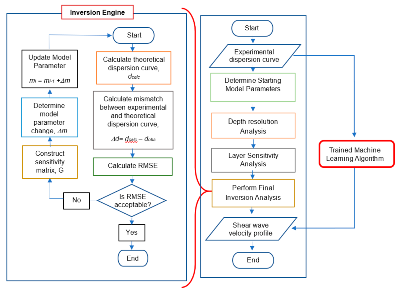
2. Inversion Analysis
3. Machine Learning (ML) Algorithms
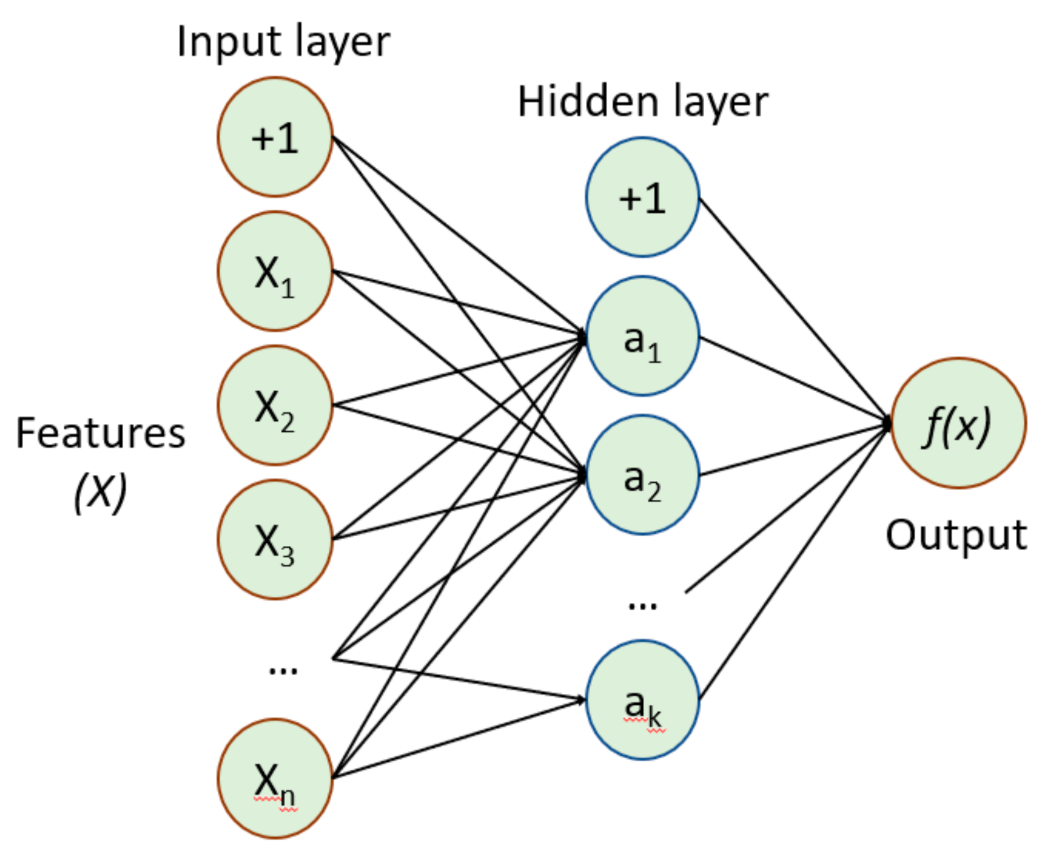
3.1. Multilayer Perceptron (MLP)
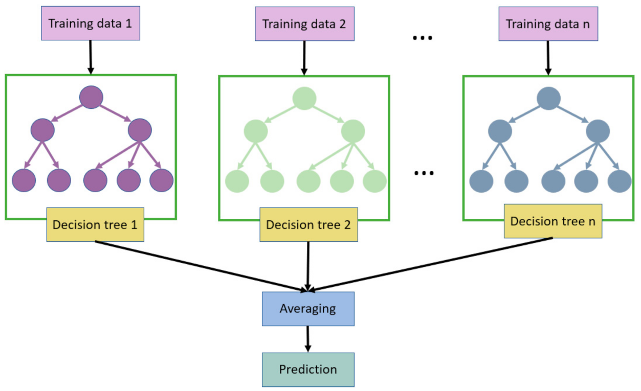
3.2. Random Forest (RF)
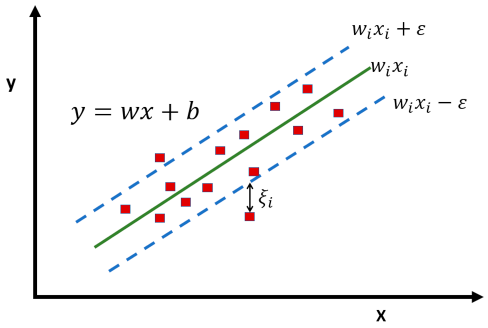
3.3. Support Vector Machine (SVM)
3.4. Linear Regression (LR)
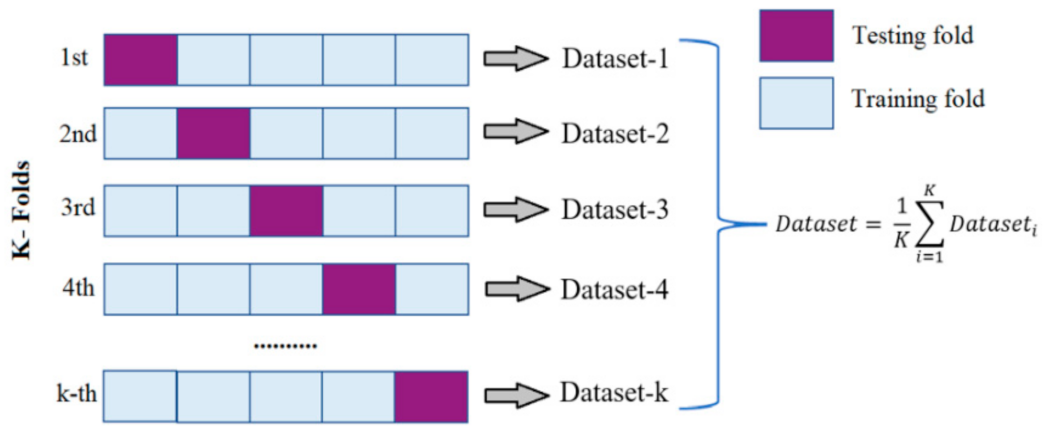
3.5. K-Fold Cross-Validation
4. Methods and Materials
5. Results and Discussions
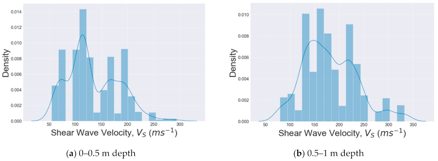
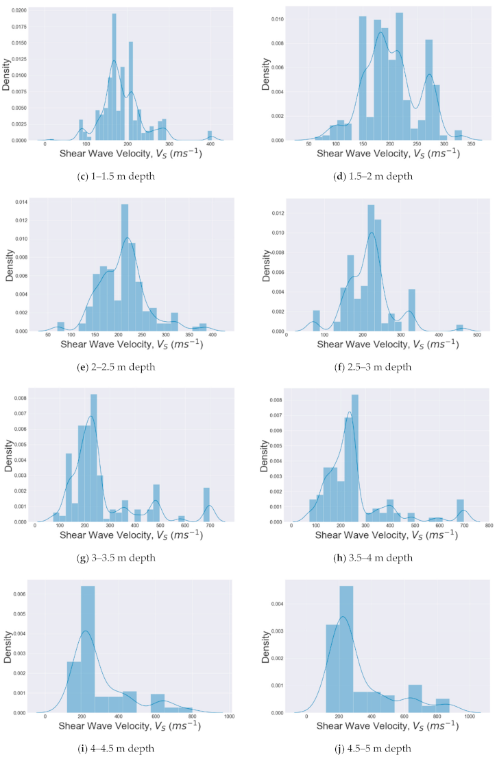
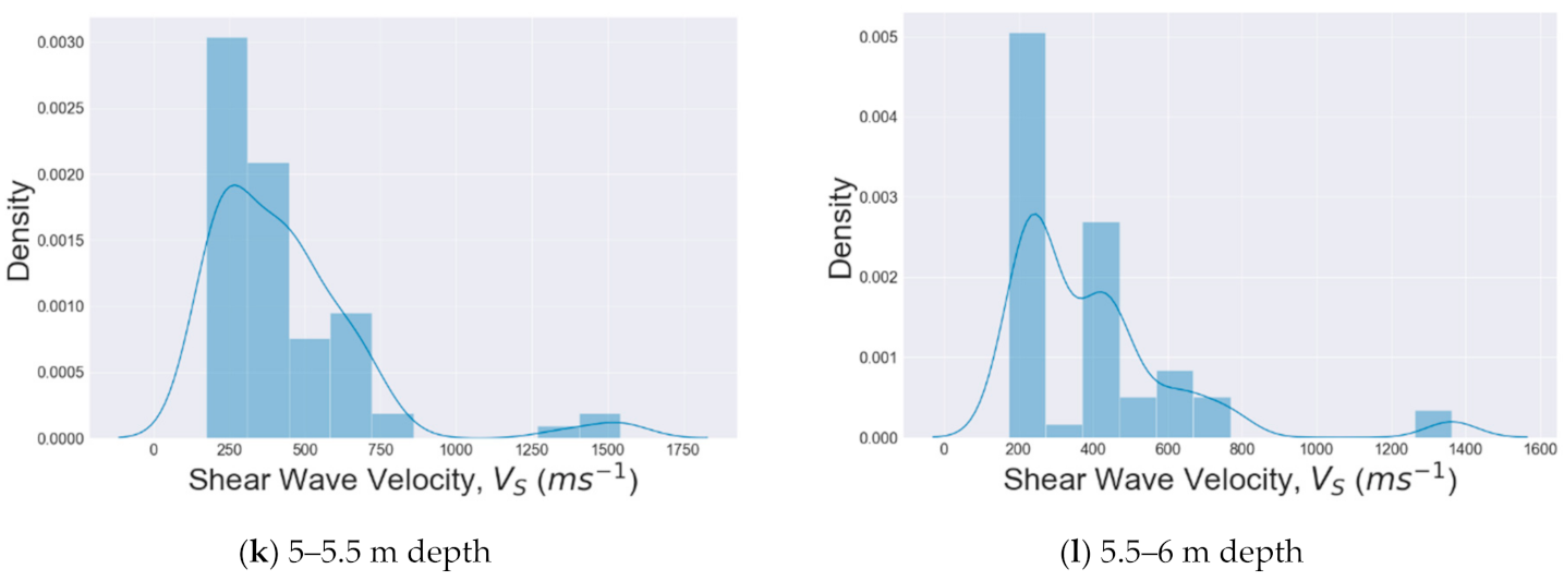
5.1. Distribution of Datasets
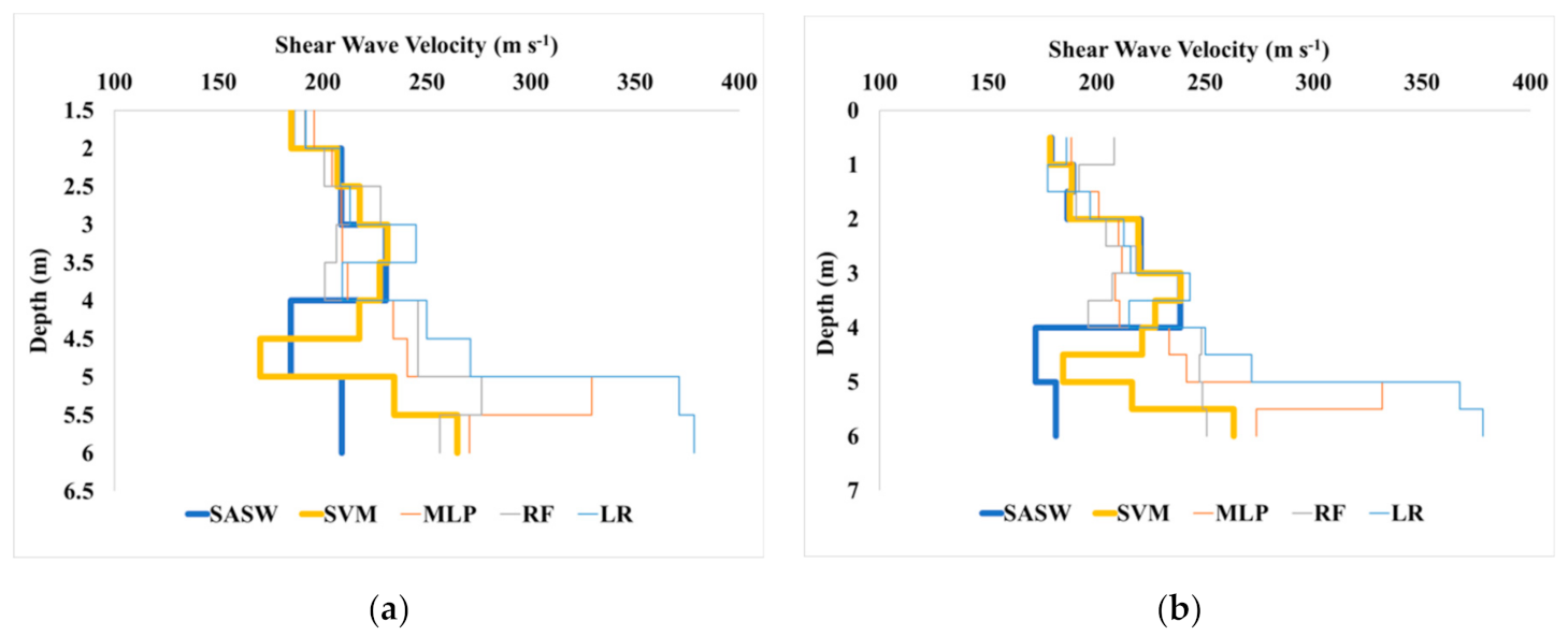
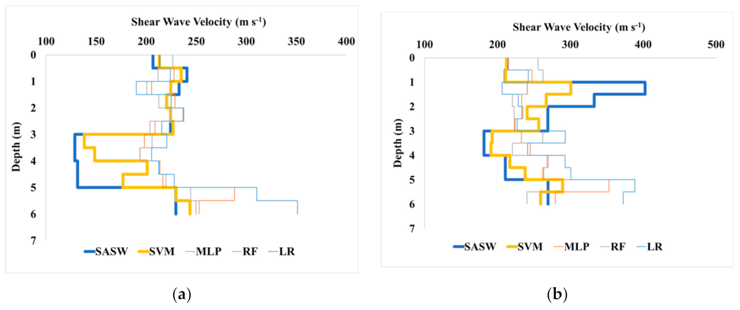
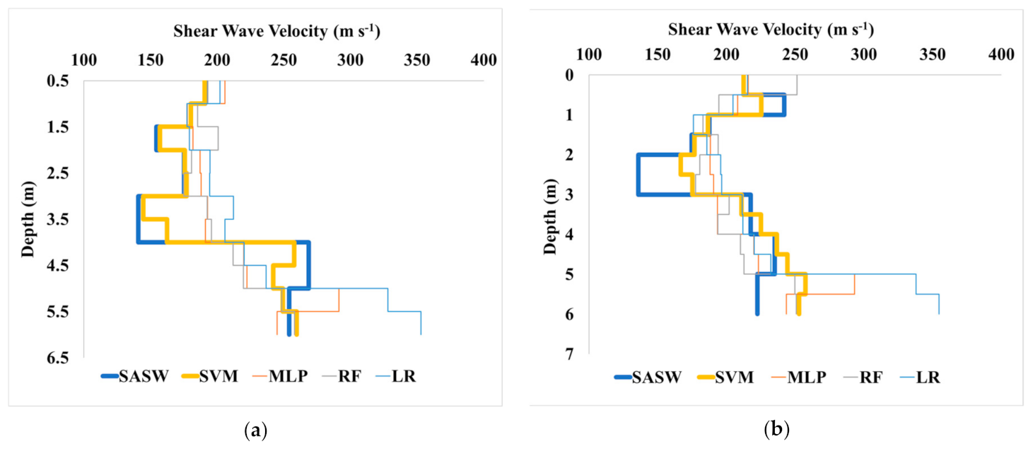
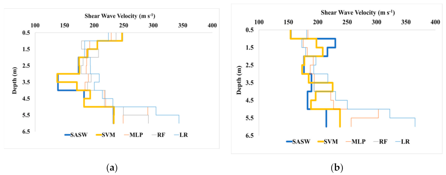
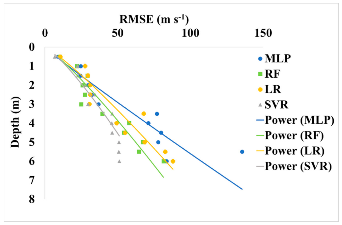
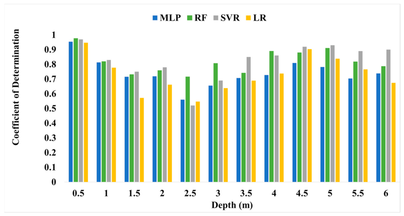
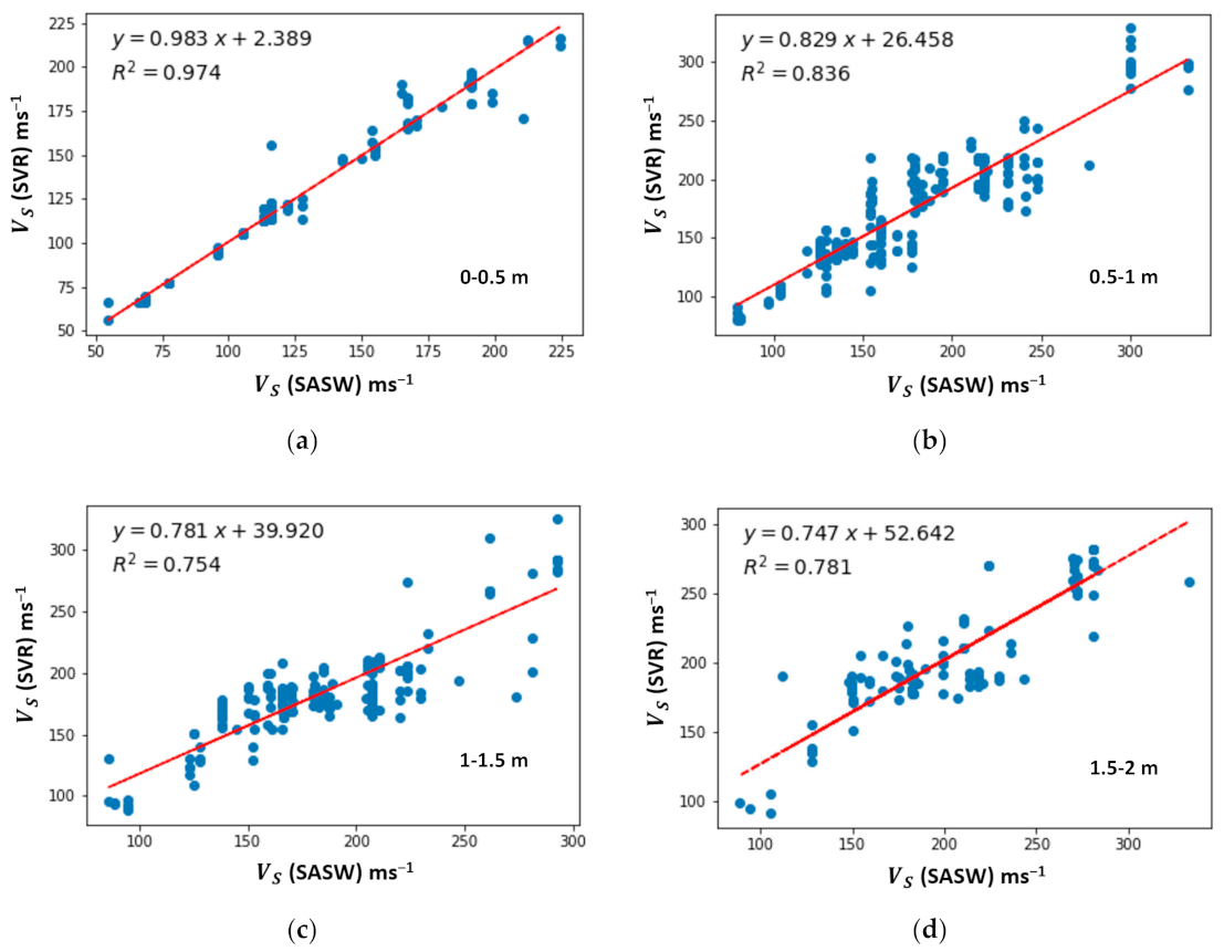
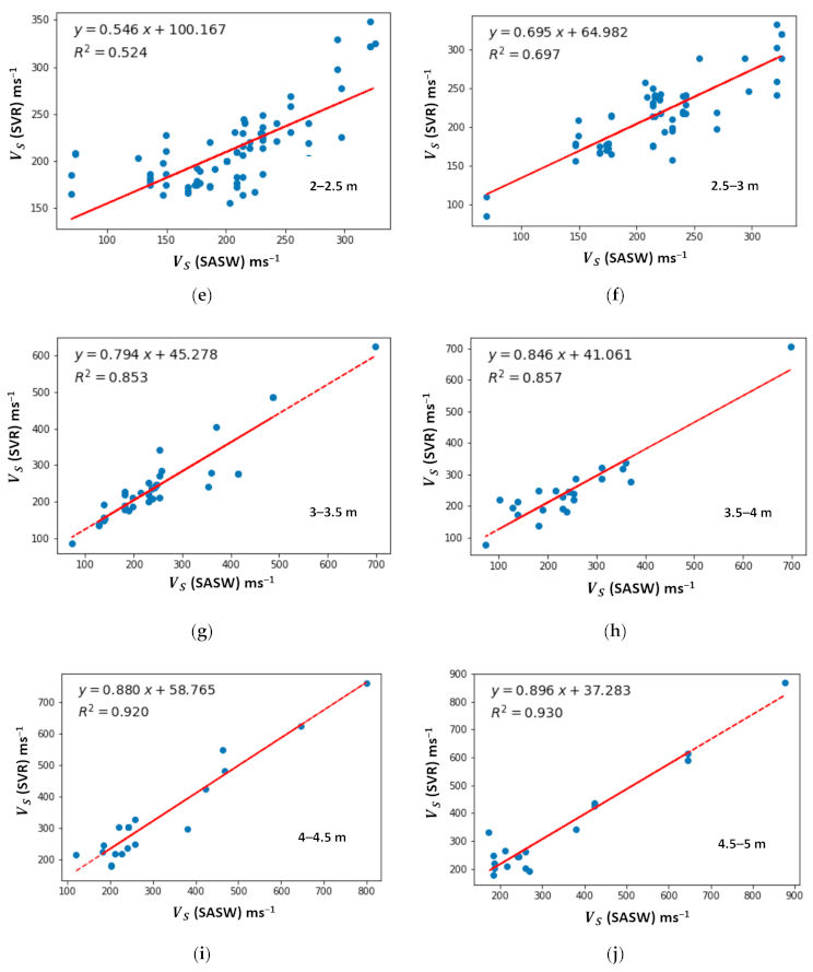
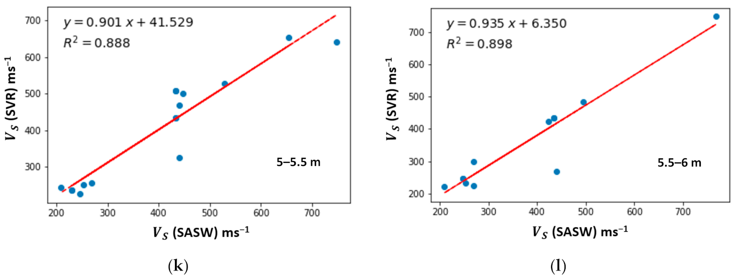
5.2. Comparative Analysis of Shear Wave Velocity for ML Algorithms
6. Conclusions
Author Contributions
Funding
Acknowledgments
Conflicts of Interest
Abbreviations
| SASW | Spectral analysis of surface wave |
| DHT | Downhole tests |
| SCPT | Seismic cone penetration testing |
| ML | Machine learning |
| ANN | Artificial neural network |
| MLP | Multilayer perceptron |
| RF | Random forest |
| SVM | Support vector machine |
| SVR | Support vector regression |
| LR | Linear regression |
| RMSE | Root mean square error |
| SMP | Starting Model Parameter |
References
- Sutherland, B.R.; Balmforth, N.J. Damping of surface waves by floating particles. Phys. Rev. Fluids 2019, 4, 14804. [Google Scholar] [CrossRef]
- Al-Hunaidi, M.O. Insights on the SASW nondestructive testing method. Can. J. Civ. Eng. 1993, 20, 940–950. [Google Scholar] [CrossRef]
- Rosyidi, S.A.; Taha, M.R.; Nayan, K.A.M. Empirical model evaluation of sedimentary residual soil bearing capacity from surface wave method. J. Eng. 2010, 22, 75–88. [Google Scholar] [CrossRef]
- Mitu, S.M.; Rahman, N.A.; Taib, A.M.; Nayan, K.A.M. Determination of soil bearing capacity from spectral analysis of surface wave test, standard penetration test and mackintosh probe test. Int. J. Innov. Technol. Explor. Eng. 2020, 9, 340–346. [Google Scholar] [CrossRef]
- Nayan, K.A.M.; Taha, M.R.; Omar, N.A.; Bawadi, N.F.; Joh, S.-H.; Omar, M.N. Determination of ultimate pile bearing capacity from a seismic method of shear wave velocity in comparison with conventional methods. J. Teknol. 2015, 74. [Google Scholar] [CrossRef] [Green Version]
- Bawadi, N.F.; Nayan, K.A.M.; Taha, M.R.; Omar, N.A. Estimate of small stiffness and damping ratio in residual soil using spectral analysis of surface wave method. In Proceedings of the MATEC Web of Conferences, Amsterdam, The Netherlands, 23–25 March 2016; Volume 47, p. 3017. [Google Scholar] [CrossRef] [Green Version]
- Widodo, W.; Rosyidi, S.A.P. Experimental investigation of seismic parameters and bearing capacity of pavement subgrade using surface wave method. Semesta Tek. 2016, 12, 68–77. [Google Scholar]
- Foti, S. Multistation Methods for Geotechnical Characterization Using Surface Waves; Politecnico di Torino: Torino, Italy, 2000. [Google Scholar] [CrossRef]
- Nazarian, S. In Situ Determination of Elastic Moduli of Soil Deposits and Pavement Systems by Spectral-Analysis-of-Surface-Waves Method; The National Academies of Sciences, Engineering, and Medicine: Washington, DC, USA, 1984. [Google Scholar]
- Haskell, N.A. The dispersion of surface waves on multilayered media. Bull. Seismol. Soc. Am. 1953, 43, 17–34. [Google Scholar]
- Thomson, W.T. Transmission of elastic waves through a stratified solid medium. J. Appl. Phys. 1950, 21, 89–93. [Google Scholar] [CrossRef]
- Ballard, R.F. Determination of Soil Shear Moduli at Depths by In-Situ Vibratory Techniques; U.S. Army Engineer Waterways Experiment Station, Engineer Research and Development Center: Vicksburg, MS, USA, 1964. [Google Scholar]
- Hossain, M.M.; Drnevich, V.P. Numerical and optimization techniques applied to surface waves for backcalculation of layer moduli. In Nondestructive Testing of Pavements and Backcalculation of Moduli; ASTM International: West Conshohocken, PA, USA, 1989; ISBN 978-0-8031-5087-4. [Google Scholar]
- Schwab, F.; Knopoff, L. Surface-wave dispersion computations. Bull. Seismol. Soc. Am. 1970, 60, 321–344. [Google Scholar]
- Yuan, D.; Nazarian, S. Automated surface wave method: Inversion technique. J. Geotech. Eng. 1993, 119, 1112–1126. [Google Scholar] [CrossRef]
- Addo, K.O.; Robertson, P.K. Shear-wave velocity measurement of soils using Rayleigh waves. Can. Geotech. J. 1992, 29, 558–568. [Google Scholar] [CrossRef]
- Zomorodian, S.M.A.; Hunaidi, O. Inversion of SASW dispersion curves based on maximum flexibility coefficients in the wave number domain. Soil Dyn. Earthq. Eng. 2006, 26, 735–752. [Google Scholar] [CrossRef]
- Meier, R.W.; Rix, G.J. An initial study of surface wave inversion using artificial neural networks. Geotech. Test. J. 1993, 16, 425–431. [Google Scholar] [CrossRef]
- Foti, S.; Hollender, F.; Garofalo, F.; Albarello, D.; Asten, M.; Bard, P.-Y.; Comina, C.; Cornou, C.; Cox, B.; Di Giulio, G. Guidelines for the good practice of surface wave analysis: A product of the InterPACIFIC project. Bull. Earthq. Eng. 2018, 16, 2367–2420. [Google Scholar] [CrossRef]
- Lysmer, J. Lumped mass method for Rayleigh waves. Bull. Seismol. Soc. Am. 1970, 60, 89–104. [Google Scholar]
- Lysmer, J.; Waas, G. Shear waves in plane infinite structures. J. Eng. Mech. 1972. [Google Scholar] [CrossRef]
- Nelder, J.A.; Mead, R. A simplex method for function minimization. Comput. J. 1965, 7, 308–313. [Google Scholar] [CrossRef]
- Williams, T.P.; Gucunski, N. Neural networks for backcalculation of moduli from SASW test. J. Comput. Civ. Eng. 1995, 9, 1–8. [Google Scholar] [CrossRef]
- Joh, S.-H.; Stokoe, K.H. Advances in Interpretation and Analysis Techniques for Spectral-Analysis-of-Surface-Waves (SASW) Measurements; Offshore Technology Research Center: College Station, TX, USA, 1997. [Google Scholar]
- Shirazi, H.; Abdallah, I.; Nazarian, S. Developing artificial neural network models to automate spectral analysis of surface wave method in pavements. J. Mater. Civ. Eng. 2009, 21, 722–729. [Google Scholar] [CrossRef]
- Alimoradi, A.; Shahsavani, H.; Rouhani, A.K. Prediction of shear wave velocity in underground layers using SASW and artificial neural networks. Engineering 2011, 3, 266. [Google Scholar] [CrossRef] [Green Version]
- Gucunski, N.; Abdallah, I.N.; Nazarian, S. ANN backcalculation of pavement profiles from the SASW test. In Pavement Subgrade, Unbound Materials, and Nondestructive Testing; American Society of Civil Engineers: Reston, VA, USA, 2000; pp. 31–50. [Google Scholar] [CrossRef]
- Omar, M.N.; Abbiss, C.P.; Taha, M.R.; Nayan, K.A.M. Prediction of long-term settlement on soft clay using shear wave velocity and damping characteristics. Eng. Geol. 2011, 123, 259–270. [Google Scholar] [CrossRef]
- Zhang, S.X.; Chan, L.S. Possible effects of misidentified mode number on Rayleigh wave inversion. J. Appl. Geophys. 2003, 53, 17–29. [Google Scholar] [CrossRef]
- Teague, D.P.; Cox, B.R. Site response implications associated with using non-unique VS profiles from surface wave inversion in comparison with other commonly used methods of accounting for VS uncertainty. Soil Dyn. Earthq. Eng. 2016, 91, 87–103. [Google Scholar] [CrossRef] [Green Version]
- Marosi, K.T.; Hiltunen, D.R. Characterization of spectral analysis of surface waves shear wave velocity measurement uncertainty. J. Geotech. Geoenvironmental Eng. 2004, 130, 1034–1041. [Google Scholar] [CrossRef]
- Chen, W.; Xie, X.; Wang, J.; Pradhan, B.; Hong, H.; Bui, D.T.; Duan, Z.; Ma, J. A comparative study of logistic model tree, random forest, and classification and regression tree models for spatial prediction of landslide susceptibility. Catena 2017, 151, 147–160. [Google Scholar] [CrossRef] [Green Version]
- Zhang, W.; Wu, C.; Li, Y.; Wang, L.; Samui, P. Assessment of pile drivability using random forest regression and multivariate adaptive regression splines. Georisk Assess. Manag. Risk Eng. Syst. Geohazards 2019, 1–14. [Google Scholar] [CrossRef]
- Zhang, W.; Wu, C.; Zhong, H.; Li, Y.; Wang, L. Prediction of undrained shear strength using extreme gradient boosting and random forest based on Bayesian optimization. Geosci. Front. 2021. [Google Scholar] [CrossRef]
- Kohestani, V.R.; Hassanlourad, M.; Ardakani, A. Evaluation of liquefaction potential based on CPT data using random forest. Nat. Hazards 2015, 79, 1079–1089. [Google Scholar] [CrossRef]
- Singh, A.; Thakur, N.; Sharma, A. A review of supervised machine learning algorithms. In Proceedings of the 2016 3rd International Conference on Computing for Sustainable Global Development (INDIACom), New Delhi, India, 16–18 March 2016; pp. 1310–1315. [Google Scholar]
- Shao, Y.-H.; Chen, W.-J.; Deng, N.-Y. Nonparallel hyperplane support vector machine for binary classification problems. Inf. Sci. (N.Y.) 2014, 263, 22–35. [Google Scholar] [CrossRef]
- Smola, A.J.; Schölkopf, B. A tutorial on support vector regression. Stat. Comput. 2004, 14, 199–222. [Google Scholar] [CrossRef] [Green Version]
- Chau, A.L.; Li, X.; Yu, W. Support vector machine classification for large datasets using decision tree and Fisher linear discriminant. Futur. Gener. Comput. Syst. 2014, 36, 57–65. [Google Scholar] [CrossRef]
- Pourghasemi, H.R.; Jirandeh, A.G.; Pradhan, B.; Xu, C.; Gokceoglu, C. Landslide susceptibility mapping using support vector machine and GIS at the Golestan Province, Iran. J. Earth Syst. Sci. 2013, 122, 349–369. [Google Scholar] [CrossRef] [Green Version]
- Wu, D.; Yang, H.; Chen, X.; He, Y.; Li, X. Application of image texture for the sorting of tea categories using multi-spectral imaging technique and support vector machine. J. Food Eng. 2008, 88, 474–483. [Google Scholar] [CrossRef]
- Wang, B.; Gong, N.Z. Stealing hyperparameters in machine learning. In Proceedings of the 2018 IEEE Symposium on Security and Privacy (SP), San Francisco, CA, USA, 20–24 May 2018; pp. 36–52. [Google Scholar] [CrossRef] [Green Version]
- Brown, L.T.; Diehl, J.G.; Nigbor, R.L. A simplified procedure to measure average shear-wave velocity to a depth of 30 meters (VS30). In Proceedings of the 12th World Conference on Earthquake Engineering, Auckland, New Zeland, 30 January–4 February 2000. [Google Scholar]
- Lin, Y.-C.; Joh, S.-H.; Stokoe, K.H. Analyst J: Analysis of the UTexas 1 surface wave dataset using the SASW methodology. In Proceedings of the Geo-Congress 2014: Geo-Characterization and Modeling for Sustainability, Atlanta, GA, USA, 23–26 February 2014; pp. 830–839. [Google Scholar] [CrossRef]
- Dunn, M.J. How reliable are your design inputs? In Proceedings of the International Seminar on Design Methods in Underground Mining, Perth, Australia, 17–19 November 2015; Australian Centre for Geomechanics; pp. 367–381. [Google Scholar] [CrossRef] [Green Version]
- Lorig, L.; Stacey, P.; Read, J. Slope design methods. Guidel. Open Pit Slope Des. 2009, 1, 237–264. [Google Scholar]


| Author | Developed Inversion Process | Generation of Dispersion Curves | Drawbacks |
|---|---|---|---|
| Nazarian [9] | Based on forward modeling | A modified version of the Haskell–Thomson matrix solution [10,11] | Quite tedious and time-consuming |
| Hossain and Drnevich [13] | Powell’s conjugate directions method for optimization | The discrete layer stiffness matrix method initially developed by Lysmer [20] and Lysmer and Waas [21] | The nontranscendental quadratic eigenvalue problem |
| Addo and Robertson [16] | Nelder and Mead’s simplex method [22] | Automated using optimization techniques with a least-squares criterion | The number of iterations needs to be increased |
| Yuan and Nazarian [15] | Linearized least-squares approximation | - | - |
| Meier and Rix [18] and Williams and Gucunski [23] | Back-calculation neural networks | - | The network required a greater number of more complex mappings for training |
| Zomorodian and Hunaidi [17] | The SASW-INVERT program | The maximum vertical flexibility coefficient of the layered soil system | - |
| Layer Number | Depth | No. of Observations |
|---|---|---|
| 1 | 0–0.5 | 756 |
| 2 | 0.5–1 | 1242 |
| 3 | 1–1.5 | 874 |
| 4 | 1.5–2 | 532 |
| 5 | 2–2.5 | 395 |
| 6 | 2.5–3 | 340 |
| 7 | 3–3.5 | 199 |
| 8 | 3.5–4 | 118 |
| 9 | 4–4.5 | 97 |
| 10 | 4.5–5 | 92 |
| 11 | 5–5.5 | 77 |
| 12 | 5.5–6 | 60 |
| Algorithm | Parameter | Setting |
|---|---|---|
| MLP | Hidden layer sizes | 3 |
| Maximum iteration | 2000 | |
| Activation | ReLU | |
| Validation threshold | 54 | |
| RF | N estimators | 50,000 |
| Criterion | MSE | |
| Minimum sample splits | 67 | |
| Maximum features | Auto | |
| Verbose | 0 | |
| SVR | C | 1 |
| Kernel | RBF | |
| Epsilon | 0.2 | |
| Maximum iteration | −1 | |
| LR | Fit intercept | True |
| n jobs | None |
| Confidence Limit (%) | Percentage Error (%) | |||||||
|---|---|---|---|---|---|---|---|---|
| Depth (m) | MLP | RF | SVR | LR | MLP | RF | SVR | LR |
| 0–0.5 | 97.41 | 97.10 | 98.06 | 96.95 | 2.59 | 2.90 | 1.94 | 3.05 |
| 0.5–1 | 92.99 | 93.18 | 93.59 | 92.11 | 7.01 | 6.82 | 6.41 | 7.89 |
| 1–1.5 | 93.04 | 91.63 | 93.50 | 91.57 | 6.96 | 8.37 | 6.50 | 8.43 |
| 1.5–2 | 91.53 | 92.61 | 91.90 | 91.08 | 8.47 | 7.39 | 8.10 | 8.92 |
| 2–2.5 | 90.83 | 92.17 | 90.16 | 91.09 | 9.17 | 7.83 | 9.84 | 8.91 |
| 2.5–3 | 89.47 | 92.88 | 91.54 | 91.28 | 10.53 | 7.12 | 8.46 | 8.72 |
| 3–3.5 | 78.01 | 88.71 | 86.81 | 80.60 | 21.99 | 11.29 | 13.19 | 19.40 |
| 3.5–4 | 79.69 | 83.46 | 86.85 | 85.92 | 20.31 | 16.54 | 13.15 | 14.08 |
| 4–4.5 | 77.18 | 84.49 | 86.78 | 84.21 | 22.82 | 15.51 | 13.22 | 15.79 |
| 4.5–5 | 77.76 | 80.78 | 85.46 | 80.42 | 22.24 | 19.22 | 14.54 | 19.58 |
| 5–5.5 | 61.27 | 81.54 | 85.50 | 76.37 | 38.73 | 18.46 | 14.50 | 23.63 |
| 5.5–6 | 76.10 | 76.71 | 85.38 | 74.87 | 23.90 | 23.29 | 14.62 | 25.13 |
| MLP | RF | SVR | LR | |||||||||
|---|---|---|---|---|---|---|---|---|---|---|---|---|
| Depth | R2 | MSE | RMSE | R2 | MSE | RMSE | R2 | MSE | RMSE | R2 | MSE | RMSE |
| 0–0.5 | 0.95 | 6.00 | 9.05 | 0.98 | 4.07 | 10.13 | 0.97 | 3.13 | 6.79 | 0.95 | 6.40 | 10.66 |
| 0.5–1 | 0.81 | 19.72 | 24.54 | 0.82 | 18.11 | 23.86 | 0.83 | 16.67 | 22.42 | 0.78 | 21.58 | 27.60 |
| 1–1.5 | 0.72 | 18.22 | 24.35 | 0.73 | 18.81 | 29.30 | 0.75 | 16.02 | 22.74 | 0.57 | 22.20 | 29.51 |
| 1.5–2 | 0.72 | 23.23 | 29.64 | 0.76 | 18.07 | 25.87 | 0.78 | 20.73 | 28.35 | 0.66 | 24.66 | 31.20 |
| 2–2.5 | 0.56 | 26.48 | 32.08 | 0.72 | 20.29 | 27.40 | 0.52 | 23.67 | 34.44 | 0.55 | 26.17 | 31.19 |
| 2.5–3 | 0.66 | 29.08 | 36.84 | 0.81 | 18.08 | 24.91 | 0.69 | 22.30 | 29.60 | 0.64 | 24.64 | 30.51 |
| 3–3.5 | 0.71 | 47.36 | 76.95 | 0.74 | 26.67 | 39.50 | 0.85 | 28.06 | 46.17 | 0.69 | 52.37 | 67.92 |
| 3.5–4 | 0.73 | 58.22 | 71.09 | 0.89 | 45.70 | 57.88 | 0.86 | 33.82 | 46.03 | 0.74 | 40.86 | 49.29 |
| 4–4.5 | 0.81 | 68.27 | 79.87 | 0.88 | 42.77 | 54.29 | 0.92 | 31.27 | 46.28 | 0.90 | 41.69 | 55.25 |
| 4.5–5 | 0.78 | 67.71 | 77.82 | 0.91 | 52.09 | 67.27 | 0.93 | 33.29 | 50.91 | 0.84 | 58.46 | 68.55 |
| 5–5.5 | 0.70 | 125.51 | 135.56 | 0.82 | 49.35 | 64.60 | 0.89 | 33.40 | 50.73 | 0.77 | 62.13 | 82.69 |
| 5.5–6 | 0.74 | 71.22 | 83.65 | 0.79 | 68.31 | 81.52 | 0.9 | 34.35 | 51.16 | 0.67 | 71.91 | 87.95 |
Publisher’s Note: MDPI stays neutral with regard to jurisdictional claims in published maps and institutional affiliations. |
© 2021 by the authors. Licensee MDPI, Basel, Switzerland. This article is an open access article distributed under the terms and conditions of the Creative Commons Attribution (CC BY) license (http://creativecommons.org/licenses/by/4.0/).
Share and Cite
Mitu, S.M.; Rahman, N.A.; Nayan, K.A.M.; Zulkifley, M.A.; Rosyidi, S.A.P. Implementation of Machine Learning Algorithms in Spectral Analysis of Surface Waves (SASW) Inversion. Appl. Sci. 2021, 11, 2557. https://doi.org/10.3390/app11062557
Mitu SM, Rahman NA, Nayan KAM, Zulkifley MA, Rosyidi SAP. Implementation of Machine Learning Algorithms in Spectral Analysis of Surface Waves (SASW) Inversion. Applied Sciences. 2021; 11(6):2557. https://doi.org/10.3390/app11062557
Chicago/Turabian StyleMitu, Sadia Mannan, Norinah Abd. Rahman, Khairul Anuar Mohd Nayan, Mohd Asyraf Zulkifley, and Sri Atmaja P. Rosyidi. 2021. "Implementation of Machine Learning Algorithms in Spectral Analysis of Surface Waves (SASW) Inversion" Applied Sciences 11, no. 6: 2557. https://doi.org/10.3390/app11062557
APA StyleMitu, S. M., Rahman, N. A., Nayan, K. A. M., Zulkifley, M. A., & Rosyidi, S. A. P. (2021). Implementation of Machine Learning Algorithms in Spectral Analysis of Surface Waves (SASW) Inversion. Applied Sciences, 11(6), 2557. https://doi.org/10.3390/app11062557