Article

Bandwidth Improvement of an Inverted-F Antenna Using Dynamic Hybrid Binary Particle Swarm Optimization

Department of Electrical and Computer Engineering, The University of Alabama, Tuscaloosa, AL 35487, USA
*
Author to whom correspondence should be addressed.
Appl. Sci. 2021, 11(6), 2559; https://doi.org/10.3390/app11062559
Submission received: 16 February 2021 / Revised: 27 February 2021 / Accepted: 9 March 2021 / Published: 12 March 2021
(This article belongs to the Special Issue Design Optimization of Antennas)

Abstract

:
This paper proposes a Dynamic Hybrid Binary Particle Swarm Optimization (DH-BPSO) algorithm to improve the bandwidth of an inverted-F antenna (IFA). The proposed algorithm improves upon the existing Artificial Immune System (AIS) algorithm by including a weighting factor that dynamically changes throughout the optimization. DH-BPSO activates or deactivates a 12 × 2 grid of parasitic patches incorporated between the IFA and ground plane. The DH-BPSO optimized and conventional IFAs are fabricated and compared while maintaining the same antenna volume. The measurement results show that the optimized IFAs have characteristics of 58.6% wider bandwidths and 5.8% higher antenna gain for various ground clearance lengths at Long Term Evolution (LTE) 700 MHz band compared to the conventional IFAs.

1. Introduction

For many years, designing broad bandwidth antennas has been of significant interest to meet ever increasing demand for a high data rate in wireless communication. In theory, the bandwidth is proportional to the antenna aperture size [1,2]. However, in the mobile device industry, the allowed antenna volume is often limited by the requirement of mechanical stability and industrial design. For this reason, an inverted-F antenna (IFA) became a commonly used compact design due to its ease of integration and omnidirectional radiation characteristic [3,4]. There is still a strong demand to increase bandwidth for a given volume. Many useful techniques come from the change in antenna geometry [5], ground plane [6], capacitive loading with several conductive parasitic patches [7], impedance matching circuit [8], substrate permittivity [9], metal chassis [10], etc. However, little has been done in designing an IFA to improve bandwidth using an optimization algorithm.
There are many algorithmic methods for optimizing antenna geometries. These optimization algorithms are mainly classified into three categories—deterministic, metaheuristic (or stochastic), and surrogate model-assisted algorithms [11]. The deterministic algorithms compute each iteration in a search space and find an optimal solution by simply following a simple line based on the previous iteration of best fitness. For this reason, it has a high possibility to become stuck in local maxima or minima [12]. By comparison, the stochastic algorithms utilize random generation of possible solutions at each iteration to increase the chance of exploring the entire search space. These algorithms are further categorized as swarm intelligence-based (SI-based) [13,14] or non-swarm intelligence-based (non-SI-based) [15,16] algorithms. The key factor for success in these algorithms is heavily dependent on how thoroughly the search space is explored. Finally, the surrogate model-based algorithms build a substitutional model with multiple pre-simulated data sets to predict solutions [17]. Examples include space mapping [18], shape-preserving response prediction [19], and artificial neural network (ANN) [20].
The SI-based algorithms are bio-inspired evolutionary algorithms and beneficial in the design case where a traditional mathematical method may fail. The genetic algorithm (GA), ant colony optimization (ACO), and particle swarm optimization (PSO) are the mainstream in antenna design. These algorithms utilize a collection of agents traversing the solution space of a cost function, sometimes called the fitness function. An agent’s position in the solution space represents a set of parameters in the cost function. An agent’s cost is the fitness function evaluated at that agent’s position. The objective of GA, ACO, and PSO is to find the global maximum or (in usual practice) global minimum of the cost function. GA does this by utilizing the principles of natural biological evolution and relying on the process of selection, crossover, and mutation [21]. In this process, only ‘elite chromosomes’ with the lowest costs survive when minimizing. The probability of survival varies with generation and the number of crossovers and mutations. ACO and PSO, by comparison, exploit the behavior of biological entities. ACO mimics the behavior of a colony of foraging ants to seek the path or position that best satisfies the cost function [22,23]. Some implementations of ACO mimic pheromones to urge agents towards promising solutions [22]. PSO imitates the behavior of a swarm of flying bees looking for food [24]. It does not exchange materials with other particles. Instead, a particle is influenced by its current position, swarm best position, and velocity. The particles are persistent and are not removed throughout the optimization process.
Recently, PSO has been utilized in a wide variety of applications in the field of antennas and electromagnetic structures. One such example is the design of novel electromagnetic materials such as phase-correcting structures [25], artificial magnetic conductors [26], and dielectric lenses [27]. Of particular note is PSO’s use in antenna gain or return loss bandwidth enhancement [28,29,30,31,32,33]. In our study, the −10 dB return loss bandwidth of an IFA antenna is enhanced by activating or deactivating a set of conductive parasitic patches and does not depend on the reproductive process of GA’s. Thus, the PSO with binary variables (so called BPSO [14]) was chosen for this study.
The first BPSO algorithm was developed by the original creators of the PSO, Kennedy and Eberhart [14]. This method utilizes the same basic process as their original PSO [24], but the particle velocity probabilistically determines whether each binary variable changes. This is done by converting the velocity into a probability via the sigmoid function. This probability determines the likelihood of a bit change in a particle’s position vector. This algorithm is commonly used in applications where the domain is discretized, and the degrees of freedom can only assume values of 0 or 1 [31,32,34,35,36]. Other BPSO algorithms have also emerged, such as Quantum BPSO (QBPSO) [37] and Artificial Immune System BPSO (AIS BPSO) [38], which is claimed to produce improved results over the original version [39]. AIS BPSO is especially attractive because both the position and the velocity of the particles are represented as strings of binary digits. In the original BPSO, distances are calculated via arithmetic operations on real numbers. AIS BPSO instead calculates velocities as the Hamming distance using Boolean operations on binary strings, allowing particles to traverse the discretized problem space more effectively. This method of optimization has already found applications in the area of antenna design [40,41,42,43,44,45]. AIS BPSO is promising due to its fast convergence, however, when applied to the antenna design it was found to be highly susceptible to converging to local minima [42].
In this paper, a novel form of BPSO is proposed to configure conductive parasitic patches of an IFA for bandwidth improvement, in addition to demonstrate the effectiveness of the evolutionary optimization algorithm in limited ground clearance areas. Here, the AIS BPSO algorithm was modified by introducing a dynamic weighting factor, creating an algorithm that effectively traverses the solution space without significant sacrifice in accuracy or convergence speed. This algorithm is termed the Dynamic Hybrid BPSO (DH-BPSO). In Section 2, we describe the operation of the DH-BPSO algorithm. In Section 3.1, we benchmark the algorithm’s performance on common test functions, compare it with other AIS algorithms, and describe the results. In Section 3.2, we apply the algorithm to design an IFA antenna. This is followed by fabrication of the designed antenna and verification of simulated results in Section 3.3. Finally, Section 4 presents the conclusion, discussion of results, and possible topics for future work.

2. Materials and Methods

The DH-BPSO algorithm includes three key components—a minimum velocity parameter, a maximum velocity parameter, and a novel weighting factor. First, the minimum velocity parameter ensures at least one bit in a particle’s position vector is flipped if the particle’s velocity is calculated to be 0. The purpose of this is to encourage particles to continue searching if they reach the swarm’s best location, so that nearby locations are also tested. Secondly, the maximum velocity parameter, originally proposed in [38], limits the maximum number of bits in the position vector that can change between iterations. Limiting particle velocities promotes a more granular exploration of the solution space. The third component is a dynamic weighting factor distinct to the DH-BPSO algorithm.
To understand the third component, we must first distinguish the global best (Gbest) and local best (Lbest) approaches. In a Gbest approach, the velocity of each particle is calculated as a combination of the global best position and the personal best position. The global best position is the position with the lowest cost encountered by any particle in the swarm. The personal best position of a particle is the position of lowest cost encountered by that particular particle. In a Lbest approach, however, the global best position is replaced with the local best position, which refers to the lowest-cost position among a particle and its k neighboring particles. In the array of particles that represent the swarm, the k neighbors of particle of index i are those particles with indices ranging from ik/2 to i + k/2 (array wraps if i + k/2 is greater than the population size). In this case, k was chosen to be two, because this neighborhood size was found to be resistant to convergence to local minima in the original study by Eberhart and Kennedy [24]. An Lbest algorithm converges more slowly but is less likely to become trapped in local minima.
The last and most important component of the DH-BPSO algorithm is the Dynamic Hybrid Weighting (DHW). The main purpose of the DHW is to provide a balance between the Lbest and Gbest approaches. In the early iterations, the particles will mostly move towards the Lbest position, but the weighting is introduced and shift towards the Gbest position after each iteration. The result is a search that explores many possibilities at the beginning but converges quickly after finding the best area.
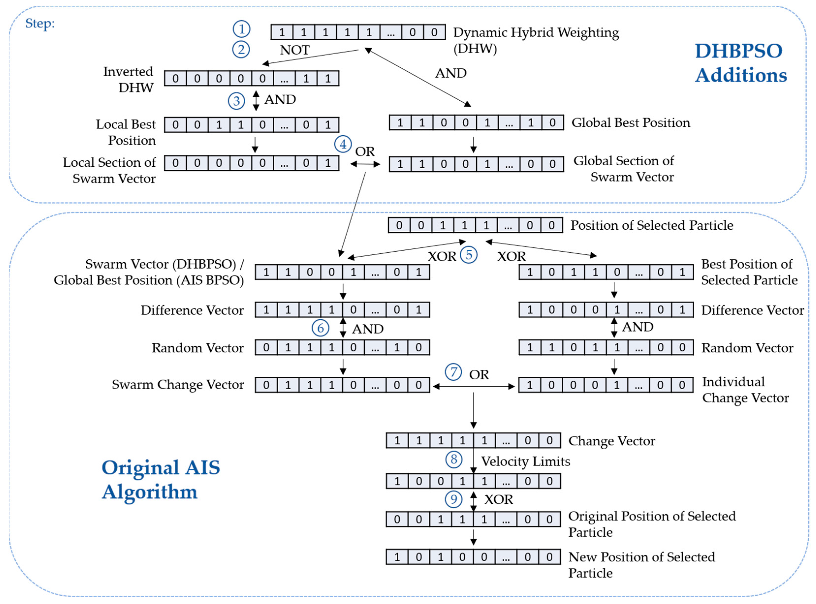
The process of the DH-BPSO algorithm is shown in Figure 1. In step 1, the DHW vector is pseudo-randomly generated. Each bit j of the DHW is determined by the following equations:
p = 1 Iteration Max   Iteration
DHW [ j ] = ( rand ( 0 , 1 ) > p )
where rand(0,1) produces a pseudo-randomly generated decimal number between 0 and 1. The variable p in Equation (1) is the probability that the jth bit in the DHW will be 0, as shown in Equation (2). It varies linearly with iteration, starting at 1 at the first iteration and progressing to 0 as the iteration number approaches the max iteration.
The logic used to produce the Swarm Vector from the proposed DHW is illustrated in steps 2 to 4 in the upper section of Figure 1. The logic takes the form of a multiplexer equation with the DHW bits serving as the select bit. Specifically,
Swarm   Vector = [ ( ¬ DHW ) Lbest ] ( DHW Gbest ) ,
where ¬ is the negation (NOT) operator, ∧ is the conjunction (AND) operator, and ∨ is the disjunction (OR) operator. Interpreting Equation (3), each bit of the Swarm Vector is copied from either the Lbest position vector or the Gbest position vector, depending on the value of the corresponding bit in the DHW vector. A 0 bit in the DHW vector means the corresponding bit in the Swarm Vector will be copied from the Lbest position vector. In the reverse case of a DHW bit of 1, the corresponding Gbest bit is copied into the corresponding bit position in the Swarm Vector. The Swarm Vector can also be interpreted as a weighted superposition of the Lbest and Gbest positions.
Steps 5 through 9 in the lower section of Figure 1 show the original AIS BPSO algorithm. This is kept the same for the DH-BPSO, only replacing the global best position with the Swarm Vector. Following the logic shown on the left of Figure 1, the difference vector d in Equation (4) is the exclusive disjunction (XOR) between the original position of a particle xi and the Swarm Vector in step 5. Thus,
x i ( Swarm   Vector ) = d .
where denotes the exclusive disjunction operation. The position of the 1 bits in this vector correspond to differing bits between the particle’s current position xi and the Swarm Vector.
In step 6, the 1 bits are randomly removed from the difference vector d by taking the conjunction of the difference vector d and a pseudo-random vector r of 0s and 1s. This yields the Swarm Change Vector.
d r = Swarm   Change   Vector
If the Swarm Vector in Equation (4) is replaced with the best position of the individual particle, the logic along the bottom right side of Figure 1 will apply, and Equation (5) will then result in the Individual Change Vector. The disjunction of the Swarm Change Vector and Individual Change Vector is taken in step 7. The result is a series of bits where the 1s indicate bits to be flipped from the original position and is known as the Change Vector—the functional equivalent of a particle’s velocity. Hence,
( Swarm   Change   Vector ) ( Individual   Change   Vector ) = Change   Vector .
Before calculating a particle’s new position, velocity limits set by the minimum and maximum velocity parameters are enforced in step 8. If the number of 1s in the Change Vector is between the minimum and maximum velocity parameters, the particle position is updated as usual. If the number is under the minimum velocity, random 0s are flipped until the condition is satisfied. Conversely, if the number is over the maximum velocity, random 1s are flipped. Finally, the new position of the particle xi+1 is found in step 9 by taking the exclusive disjunction of the Change Vector and the particle’s current position xi. Finally,
x i ( Change   Vector ) = x i + 1 .
This DH-BPSO algorithm is executed using the IronPython2.7 interpreter built in to ANSYS HFSS.

3. Results

3.1. Algorithm Performance

The original AIS algorithms [38] is implemented using the Gbest approach. Comparing the dynamic hybrid approach with the Gbest alone ignores the other possible AIS BPSO approaches, namely Lbest and static hybrid. Thus the AIS Gbest algorithm in [38] is extended to implement Lbest and static hybrid approaches to provide a comprehensive comparison of the these algorithms with DH-BPSO. The Lbest simply replaces the global best position with the local best position in the original AIS algorithm in [38]. The static hybrid approach (AIS Hybrid) uses a combined Gbest and Lbest approach with the probability threshold p from Equation (1) fixed to 0.5. Thus, a broad range of AIS approaches were considered for the following analysis.
Each of the four optimization algorithms were performed 500 times with a population of 10 particles and a maximum iteration of 200. The number of variables N was set to 100. The algorithms operate on four well-known test functions: Sphere, Griewank, Holder Table 2, and Eggholder functions [46]. The definitions and their global minima of the test functions are summarized in Table 1 below.
The input vector x to the Sphere and Griewank fucntions represents a particle’s position as a list of raw bits x n . The Eggholder and Holder Table 2 functions take two real-valued parameters. To use these functions, each particles’ position, expressed as a binary string of 100 bits, is converted to a real number using a sign-magnitude fixed precision encoding scheme. First, each bit string is divided into two 50-bit strings. The leftmost bit of each string is the sign bit. For the Eggholder function, the next nine bits are used as the integer bits, leaving 40 precision bits. This naturally constrains the domain of x n to ±512. The encoding for the Holder Table 2 function uses three integer bits and 46 precision bits, naturally restricting the domain to ±8. Restricting the domain to a power of 2 simplifies the enforcement of boundary conditions in binary algorithms such as AIS BPSO. The domain is also within the ±10 domain of the Holder Table 2 function as defined in [46].
Figure 2 plots against iteration number each algorithm’s average global best cost over 500 independent optimizations for the aforementioned test functions. From Figure 2a,b, it is evident that Griewank and Sphere functions pose little difficulty in optimizing for any algorithm. The dynamic behavior of DH-BPSO is also clearly shown in that the DH-BPSO convergence curves mimic those of the AIS Lbest algorithm for a brief period at the beginning of the optimization. DH-BPSO quickly begins to accelerate, deviating away from the AIS Lbest curve and closely approaching the AIS Gbest and Hybrid curves some iterations later.
Although the Griewank and Sphere function are multi-modal, they are bowl-shaped cost functions with a singular global minimum. Such functions are better optimized by Gbest algorithms which accelerate towards this global minimum once any one particle discovers it. This can be observed from Figure 2a,b. As expected, the AIS Gbest and Hybrid algorithms converged the fastest to the minimum cost. The Eggholder and Holder Table 2 functions, however, are significantly more complicated multi-modal cost functions. The Eggholder function is especially difficult due to the presence of several local minima of comparable magnitude to the global minimum. These functions are therefore better optimized by Lbest algorithms. Results in Figure 2c,d confirm this. AIS Lbest and DH-BPSO outperformed AIS Gbest and AIS Hybrid. It is also with these functions that the superiority of the DH-BPSO algorithm can be seen. The DH-BPSO algorithm consistently reached the lowest minimum of any of the other algorithms. It also discovered the lowest minimum quicker than the AIS Lbest algorithm, shown by the steeper slope of the DH-BPSO convergence trace. These results also indicate that dynamic hybrid algorithms such as DH-BPSO promise better performance on complex, difficult-to-optimize cost functions than static hybrid algorithms such as AIS Hybrid.
Table 2 provides column plots of performance statistics calculated during the optimizations. Three metrics are provided. First, the average minimum cost is provided. This is calculated by taking the average over all trials of the minimum cost achieved by each optimization. Secondly, the average iterations to reach the minimum cost is given. This is calculated as an average over the 500 trials of the iterations required to first reach that trial’s final minimum cost. Lastly, the average time to reach the minimum cost is given. For each of the 500 trials, the time required to first reach the ultimate minimum cost is calculated and averaged over the 500 trials. These benchmarks were performed on a computer equipped with an Intel i7-6560u 2.2 GHz quad-core processor and 8 GB DDR3 RAM. The raw values of the performance metrics are given in Appendix A in Table A1.
The qualitative conclusions gleaned from Figure 2 can now be quantified. For the simple Sphere function, the difference in average minimum cost achieved is negligible, varying from 0.014 for AIS Hybrid to 0.03 for AIS Lbest. The average iterations to the minimum cost show a similar pattern, with AIS Hybrid leading with 115.028 iterations on average to converge to a minimum value. Although it did not outperform AIS Gbest or Hybrid, DH-BPSO did outperform AIS Lbest in both average minimum cost and average iterations required to minimize. For the Sphere function, DH-BPSO required 115.348 ± 26.48 average iterations to find an average minimum of 0.022 ± 0.147, compared to AIS Lbest’s average minimum of 0.03 ± 0.171 achieved in 123.88 ± 24.822 average iterations. Note that the DH-BPSO average minimum cost has a smaller standard deviation, which is an indication of consistency. The performance of these two algorithms on the Griewank function exhibits a similar pattern, namely that DH-BPSO achieves a lower cost in less iterations on average. These results once again show that dynamic hybrid algorithms can exceed in performance compared to their static hybrid or non-hybrid counterparts.
The performance of DH-BPSO and AIS Lbest excel when optimizing the more complex Holder Table 2 and Eggholder functions. In these trials, DH-BPSO outperformed the other algorithms in minimum cost achieved. For Holder Table 2, DH-BPSO achieved a minimum cost of −9.336 ± 0.597 compared to the next best minimum cost of −9.278 ± 0.811 achieved by AIS Lbest. The true global minimum of −9.45799 lies within one standard deviation of both results, however, DH-BPSO consistently achieved a lower minimum cost, evidenced by the lower average minimum and smaller standard deviation. A similar conclusion can be made comparing AIS Lbest and DH-BPSO performance optimizing the Eggholder function. Note that while the AIS Gbest and Hybrid algorithms reached minima significantly faster, the minima they converge to were larger than those reached by AIS Lbest or DH-BPSO.
In terms of real time to converge to a minimum cost, AIS Gbest and Hybrid algorithms exceed. However, this convergence speed comes at the cost of a larger minimum cost achieved. Additionally, several factors influence the real time required to achieve a minimum cost. These include the method by which the algorithm is implemented in code and other processes executing on the computer during benchmarking. Hence, average iterations to converge to a minimum is a more useful metric. This and the average minimum cost achieved are the primary metrics used to select an algorithm for antenna design applications.
When applying PSO algorithms to antenna design, the cost function is usually some electrical characteristic of an antenna determined via a full-wave simulation. In such cases, each particle represents an antenna configuration that must be simulated to determine the cost. If there are several design variables (i.e., large N), the optimization may run for an unacceptably long time or consume an excessive amount of computational resources. Hence, when selecting an algorithm for antenna design, the statistic of interest is the average minimum cost achieved and the average iterations required to reach a minimum cost. Additionally, the changes in electrical characteristics induced by a change in antenna structure are often unpredictable. It is likely multiple satisfactory solutions exist. That is, the solution space of such a problem may have multiple, distinctly large minima, and only one of which may be the true global minima. The shape of the Eggholder function emulates this. An algorithm that explores a wide range of solutions but is resilient to premature convergence to local minima is ideal. Given these criteria, the DH-BPSO algorithm promises the best performance. It exceled in optimizing the Eggholder function in both average minimum cost achieved and average iterations required to reach a minimum cost. Thus, the DH-BPSO algorithm appears a promising tool in the design and optimization of antennas.

3.2. IFA Design Using DH-BPSO

An application of the proposed DH-BPSO to an antenna design is demonstrated in this section. Although any antenna can be chosen to demonstrate an application of DH-BPSO, we select a planar IFA, one of the common antenna geometries in mobile devices. The IFA is modelled with an electromagnetic simulator, ANSYS HFSS 2019 R2. The design parameters of the IFA geometry are shown in Figure 3.
The resonant frequency of the IFA is mainly determined by arm_z which is approximately a quarter-wave long at the resonant frequency. The width of the conducting IFA arm is denoted as arm_w and is fixed to be 1 mm. The input impedance is controlled by adjusting feed_gap and feed_z. The slot_w is the spacing between the parasitic patches and set to be 0.25 mm. A 1 mm thick FR4 substrate with standard double-sided copper cladding is used. The permittivity and loss tangent of the FR4 substrate are 4.4 and 0.02, respectively. The size of the substrate is fixed for all IFAs and defined with sub_z and sub_x which is 85 × 140 mm2. The width of the parasitic patches (patch_z2) is fixed to be 7.05 mm, whereas the width of the patches closest to the feed and grounding strip (patch_z1) varies depending on feed position for impedance matching. The feed_z is set to be 2.5 mm. The ground clearance GND_clr is the distance between the IFA arm and ground plane. The ground clearance region is divided into 24 sections that represent either activated or deactivated parasitic patches. The yellow squares represent patches that are activated to be conductive and the grey squares represent the deactivated patches to be non-conductive. The state (active or inactive) of a particular parasitic patch maps to the state of a bit (1 or 0) in the integer that represents the position of a particle. Hence there are 16,777,216 (224) possible patch configurations, and the particles of the DH-BPSO algorithm traverse a discrete 24-dimensional space. The conductive elements are modelled as copper sheets with a thickness of 35 µm and a conductivity of 5.8 × 10⁸ S/m. A unique antenna design is created for a range of values of ground clearance (GND_clr) from 9 to 14 mm. For each clearance length, the reference base design (i.e., no active parasitic elements) is optimized to resonate at 720 MHz by adjusting the feed_gap and arm_z parameters. The exact value of these and other parameters are given in Table 3. The parasitic patch design is then optimized by applying the DH-BPSO algorithm with 10 particles, a maximum velocity of 10, and a minimum velocity of 1. The goal of the optimization is to improve the −10 dB bandwidth of the reflection coefficient of the IFAs, which is simulated from 500 MHz to 1 GHz. Because DH-BPSO searches for the global minima of a cost function, the negative of the −10 dB bandwidth is used as the cost function. The minima of this cost function correspond to wider bandwidths.
To show a fair comparison, three different antenna patch configurations were simulated: (1) a base IFA design with no parasitic patches as a reference, (2) a base IFA with all parasitic patches activated, and (3) the optimized IFA. The reflection coefficient versus frequency plot for the 14 mm ground clearance IFA is shown in Figure 4. The simulation results indicate that the DH-BPSO algorithm improves the bandwidth from the conventional IFA without the parasitic patches by 74.3%. The base IFA with all patches activated shows poor input impedance mismatch and shift of resonant frequency to the lower frequency. Regarding the radiation pattern of the three different IFAs shown in Figure 5, the optimized IFA shows similar omnidirectional pattern on φ = 90° plane and figure “8” shape on φ = 0° plane relative to the base IFA. Furthermore, the base IFA with all patches shows a smaller gain over all azimuth and elevation angles. Additionally, the effect of the optimal patch configuration in the realized gain is minimal and the peak realized gain is 2.7 dBi. Therefore, the DH-BPSO-optimized IFA significantly outperforms the reference IFA in bandwidth.
In addition to the 14 mm ground clearance, the bandwidth effect was further investigated by reducing the size of the ground clearance in the base and optimized IFAs. In our simulations, the ground clearance was varied from 9 mm to 14 mm with an increment of 1 mm. Figure 6 shows the optimized antenna geometries for the different ground clearance. Active parasitic patches are clustered around the feed, ground strip, and IFA arm. This is because of the strong, high-frequency current flow in this area. The patch configurations in Figure 6d,e appear identical, however the size of the parasitics differs between the two models, leading to a difference in bandwidth.
Figure 7 compares the simulated bandwidths of the DH-BPSO optimized and base IFAs for each ground clearance length. At each clearance length, the optimized IFAs show a marked improvement in bandwidth over the base IFA. The magnitude of this improvement increases with increasing ground clearance length. In addition, the rate of bandwidth increase is higher in the optimized IFAs than in the base IFA. The minimum simulated bandwidth increase is 20.3% at 9 mm. The maximum simulated bandwidth increase is 74.3% at 14 mm, as mentioned previously.

3.3. Fabrication and Measurement

Following optimization via DH-BPSO, optimized and base IFAs were fabricated with ground clearance lengths of 9, 10, 12, and 14 mm using a LPKF S4 laser milling machine. The fabricated antennas with semi-rigid, 50 Ω coaxial connectors attached are depicted in Figure 8. The reflection coefficient of each antenna was measured over a frequency range of 0.5 to 1 GHz using an Agilent E8364C PNA. Figure 7 compares the performance of the fabricated antennas with the simulations of the base and DH-BPSO-optimized designs. The optimized designs show good agreement between simulation and measurement results overall. The 14 mm ground clearance length IFA showed a measured bandwidth increase of 58.6%. The discrepancy from the simulated bandwidth increase can be attributed to fabrication tolerances. The measurements of the base IFA also show good agreement with the simulations, with a slight discrepancy of 6.83 MHz at 9 mm clearance length. Thus, the measurement results validate the results of the simulations and show that the DH-BPSO algorithm successfully found an optimal parasitic patch configuration to increase bandwidth of the IFA.
The radiation patterns, peak gain, and radiation efficiency were measured using a Model 2100D anechoic chamber from The Howland Company. Figure 9 shows the measurement setup in the anechoic chamber. The simulated and measured radiation patterns are shown in Table 4 below. The omnidirectional radiation patterns were observed on the φ = 90° plane. In the φ = 90° plane, figure “8” shapes of radiation were measured, indicating characteristics of a dipole antenna. For the both principle planes, the simulated and measured results show good agreement. The DH-BPSO optimized IFA shows similar radiation characteristics as those of the base IFA despite the presence of parasitic patches. The simulated current distribution is also shown in Table 4. The current is strongest around the feed, grounding strip, and activated parasitic patches, whereas it is weakest at the end of the IFA arm and FR4 substrate. This supports the omnidirectional and figure “8” shape of radiation patterns.
Although the goal of the DH-BPSO algorithm was to improve the −10 dB bandwidth, improvements in peak gain and efficiency are also observed. Figure 10 compares the peak gain and efficiency between the simulations and measurements. According to the simulated results, the DH-BPSO-optimized IFA shows a higher peak gain for all ground clearance lengths. The largest increase in peak gain is 5.8% observed at 14 mm ground clearance length. The peak gain slightly increases as the ground clearance becomes larger for both the simulated and measured results, as expected. The measured optimized peak gain varies from 2.9 to 3.2 dBi. In addition, the radiation efficiency of the optimized IFA improved by as much as 6.4% compared to the base IFA efficiency. The measured radiation efficiency ranges from 89% to 97% for 9 and 14 mm ground clearances, respectively. The discrepancy between the simulated and measured results can be attributed to fabrication tolerances. Thus, the radiation pattern, gain, and efficiency of the proposed IFA is suitable for mobile devices.
Table 5 compares the bandwidth enhancement results of this article to those achieved in recent literature. Clark and Jeong [31] make use of the Hybrid PSO (HPSO) algorithm, which makes use of both the real PSO algorithm [24] and the original binary PSO [14] to simultaneously optimize the configuration and spacing between parasitic patches surrounding a microstrip patch antenna. However, we achieve a markedly higher bandwidth improvement of 58.6% using DH-BPSO as opposed to the 16.3% achieved using HBPSO. Kibria et al. in [30] and Verma, et al. in [47] achieve bandwidth enhancement using curve fitting in conjunction with PSO. Instead of using PSO as an external optimizer of a full-wave simulator, IE3D is used to generate data that relates the antenna bandwidth to the physical dimensions of the patch antennas to be optimized. Analytical functions are synthesized using curve fitting and PSO is used to find the maximum of these functions, thus determining the antenna dimensions required for wider bandwidths. Ref. [30] is distinct in their treatment of particle boundary conditions, which they claim to reduce computation time. The bandwidth improvement achieved by such an approach is 13.5% and 13.8% for [47], respectively, compared to that achieved by DH-BPSO. Mirhadi et al. [48] utilize the original binary PSO algorithm [14] to maximize the voltage standing wave ratio (VSWR) of a pixelized planar monopole antenna in the frequency range 3.1 to 10.6 GHz. The antenna VSWR is simulated via the Discrete Green’s function instead of a full-wave simulator such as HFSS or IE3D. Their optimized antenna achieves a 27.4% increase in bandwidth relative to a reference staircase monopole antenna with bandwidth 6.2 GHz. Shandilya et al. [49] use the continuous-domain real PSO to determine the dimensions of a Printed Log Periodic Dipole Array (PLPDA) antenna for maximum bandwidth. They enhance the initial 5 GHz bandwidth to 7.4 GHz, giving a measured increase of 48%. Compared to existing literature, DH-BPSO achieved a significantly higher bandwidth increase.

4. Discussion

A new DH-BPSO was developed as a modification of the original AIS algorithm by introducing the DHW. DH-BPSO exhibited an affinity in optimizing complex, varying functions such as the Eggholder and Holder Table 2 functions. Its performance exceeded that of its AIS Hybrid, Gbest, and Lbest counterparts in terms of minimum cost achieved and iterations required to reach a minimum cost. Thus DH-BPSO has advantages in both speed and efficiency when solving problems with many satisfactory solutions and where iterations are computationally demanding. Future work may explore the effectiveness of non-linear, higher-order weightings on certain types of problems. For example, an exponential or quadratic weighting strongly favoring a Lbest approach may make DH-BPSO better suited for large domain problems with a variety of solutions.
A drawback of DH-BPSO is its dependence on the maximum iterations shown in Equation (1). For small values of the maximum iteration, DH-BPSO would quickly transition to a Gbest approach and would lose the benefit of the explorative Lbest approach. Thus, a possible avenue of research is a dynamic weighting scheme that does not depend on the maximum iteration but possibly adapts to the current speed of convergence, which could be determined from the slope of its convergence trace.
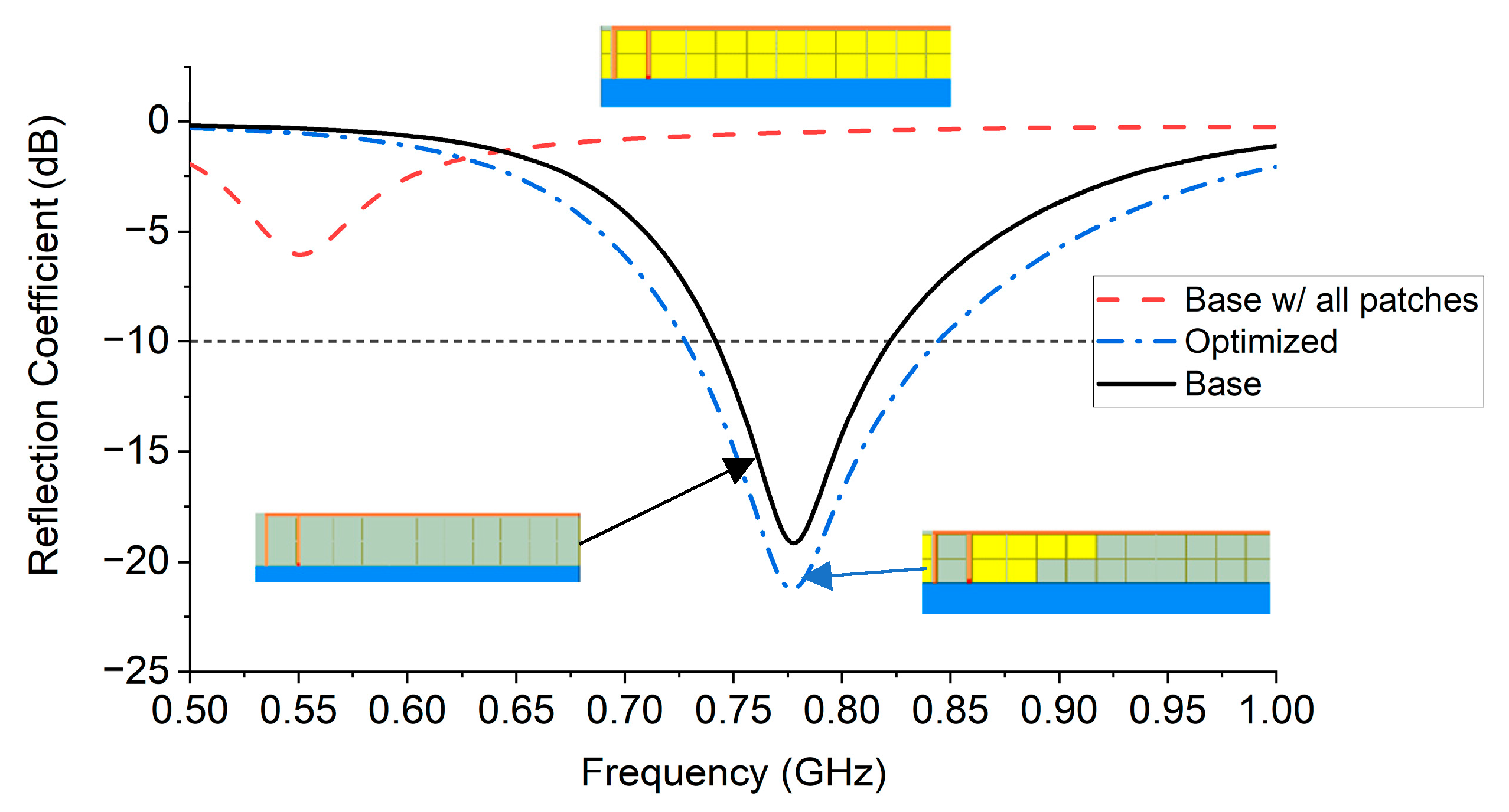
Experiments with IFA optimization show the applicability of DH-BPSO. Both measurements and simulations show an improvement in the −10 dB bandwidth, the peak gain, and the efficiency when optimized via DH-BPSO. Optimizations with this algorithm improved simulated bandwidths by as much as 74.3% and measured bandwidths by as much as 58.6%. Bandwidth improvements could be improved by further pixelating the ground clearance area, simultaneously decreasing the patch size and increasing the number of parasitic patches. This would facilitate finer control of the antenna configuration by the algorithm, possibly allowing for better solutions with wider bandwidths.
Although this paper only considered the IFA, the process can be easily applied to other antenna geometries such as patch, slot, and loop antennas. The parasitic patches can be configured around each antenna as previously done, and the number of dimensions of the optimization can be increased appropriately. This will lead to a longer convergence time, but in theory the number of parasitic patches can be increased indefinitely with appropriate time and computing resources.
Another potential future area of work is extending DH-BPSO to find solutions to multi-objective problems. For example, the radiation pattern could be analyzed in addition to bandwidth. Additionally, desired resonant frequencies may be incorporated into the cost function to ensure increased bandwidth in a frequency band of interest. The principle of a dynamic weighting factor can also be applied beyond just the AIS BPSO to any PSO that incorporates local and global best approaches.

Author Contributions

Conceptualization, G.G. and N.J.; methodology, J.A., G.G. and N.J.; software, J.A. and G.G.; validation, J.A.; formal analysis, J.A., G.G. and N.J.; investigation, J.A., G.G. and N.J.; resources, N.J.; data curation, J.A., G.G., and N.J.; writing—original draft preparation, J.A., G.G. and N.J.; writing—review and editing, J.A., G.G. and N.J.; visualization, J.A., G.G. and N.J.; supervision, N.J.; project administration, N.J.; funding acquisition, N.J. All authors have read and agreed to the published version of the manuscript.

Funding

This research was funded by the Remote Sensing Center of the University of Alabama.

Institutional Review Board Statement

Not Applicable.

Informed Consent Statement

Not Applicable.

Acknowledgments

We would like to acknowledge Deepak N. Elluru for his assistance in the antenna fabrication process.

Conflicts of Interest

The authors declare no conflict of interest.

Appendix A

Table A1. Comparison of Artificial Immune System (AIS) BPSO algorithms solving 100-variable test functions using 10 particles and a maximum iteration of 200 averaged over 500 runs.
MetricFunctionAIS GbestAIS HybridAIS LbestDH-BPSO (Proposed)
Avg. Minimum CostSphere0.018 ± 0.1330.014 ± 0.1330.03 ± 0.1710.022 ± 0.147
Griewank2.024 × 10−4 ± 1.749 × 1031.332 × 10−4 ± 9.454 × 10−42.662 × 10−4 ± 1.340 × 10−32.061 × 10−4 ± 1.203 × 10⁻³
Holder Table 2−9.035 ± 1.216−9.159 ± 1.005−9.278 ± 0.811−9.336 ± 0.597
Eggholder−720.067 ± 70.824−738.278 ± 52.024−743.676 ± 55.764−748.929 ± 52.036
Avg. Iterations to MinimumSphere114.716 ± 25.445115.028 ± 25.379123.88 ± 24.822115.348 ± 26.480
Griewank123.132 ± 23.905127.682 ± 25.181143.766 ± 21.836132.308 ± 24.912
Holder Table 2 149.648 ± 30.729157.202 ± 27.688182.274 ± 16.495166.902 ± 23.698
Eggholder164.19 ± 29.857176.082 ± 24.409192.566 ± 11.382183.962 ± 18.847
Avg. Time to Minimum (ms)Sphere184.192 ± 83.509190.627 ± 57.019229.474 ± 62.214270.223 ± 95.012
Griewank239.142 ± 51.089227.947 ± 34.787267.383 ± 32.331243.914 ± 34.749
Holder Table 2337.449 ± 174.633428.906 ± 200.488838.32 ± 304.057635.229 ± 165.255
Eggholder257.806 ± 47.540294.785 ± 47.201340.074 ± 29.136335.925 ± 48.022

References

  1. Chu, L.J. Physical limitations of omni-directional antennas. J. Appl. Phys. 1948, 19, 1163–1175. [Google Scholar] [CrossRef] [Green Version]
  2. Harrington, R.F. Effect of antenna size on gain, bandwidth, and efficiency. J. Res. Nat. Bur. Stand 1960, 64, 1–12. [Google Scholar] [CrossRef]
  3. Liu, H.; Lin, S.; Yang, C. Compact Inverted-F Antenna with Meander Shorting Strip for Laptop Computer WLAN Applications. IEEE Antennas Wirel. Propag. Lett. 2011, 10, 540–543. [Google Scholar] [CrossRef]
  4. Young-Bae, K.; Jung-Ick, M.; Seong-Ook, P. An internal triple-band planar inverted-F antenna. IEEE Antennas Wirel. Propag. Lett. 2003, 2, 341–344. [Google Scholar] [CrossRef]
  5. Hoon, P.; Kyungho, C.; Jaehoon, C. Design of a planar inverted-F Antenna with very wide impedance bandwidth. IEEE Microw. Wirel. Compon. Lett. 2006, 16, 113–115. [Google Scholar] [CrossRef]
  6. Huynh, M.; Stutzman, W. Ground plane effects on planar inverted-F antenna (PIFA) performance. IEE Proc. Microw. Antennas Propag. 2003, 150, 209–213. [Google Scholar] [CrossRef] [Green Version]
  7. Ciais, P.; Staraj, R.; Kossiavas, G.; Luxey, C. Design of an internal quad-band antenna for mobile phones. IEEE Microw. Wirel. Compon. Lett. 2004, 14, 148–150. [Google Scholar] [CrossRef]
  8. Komulainen, M.; Berg, M.; Jantunen, H.; Salonen, E.T.; Free, C. A Frequency Tuning Method for a Planar Inverted-F Antenna. IEEE Trans. Antennas Propag. 2008, 56, 944–950. [Google Scholar] [CrossRef] [Green Version]
  9. Hwang, Y.; Zhang, Y.P.; Zheng, G.X.; Lo, T.K.C. Planar inverted F antenna loaded with high permittivity material. Electron. Lett. 1995, 31, 1710–1712. [Google Scholar] [CrossRef]
  10. Liu, Y.; Zhang, J.; Ren, A.; Wang, H.; Sim, C. TCM-Based Hepta-Band Antenna With Small Clearance for Metal-Rimmed Mobile Phone Applications. IEEE Antennas Wirel. Propag. Lett. 2019, 18, 717–721. [Google Scholar] [CrossRef]
  11. Sahal, M.; Tiwari, V.; Jhajhria, T. Optimization Algorithms for Antenna Design, Array Thinning, and Radiation Pattern Synthesis; Springer: Singapore, 2021; pp. 319–326. [Google Scholar]
  12. Montaser, A.M.; Mahmoud, K.R. Antenna current optimization for optimal antenna design in different frequency bands using VSO-NM algorithm. Int. J. RF Microw. Comput. Aided Eng. 2017, 27, e21104. [Google Scholar] [CrossRef]
  13. Rahmat-Samii, Y. Modern Antenna Designs using Nature Inspired Optimization Techniques: Let Darwin and the bees help designing your Multi band MIMO antennas. In Proceedings of the 2007 IEEE Radio and Wireless Symposium, Long Beach, CA, USA, 9–11 June 2007; pp. 463–466. [Google Scholar]
  14. Kennedy, J.; Eberhart, R.C. A discrete binary version of the particle swarm algorithm. In Proceedings of the 1997 IEEE International Conference on Systems, Man, and Cybernetics. Computational Cybernetics and Simulation, Orlando, FL, USA, 12–15 October 1997; Volume 4105, pp. 4104–4108. [Google Scholar]
  15. Weile, D.S.; Michielssen, E. Genetic algorithm optimization applied to electromagnetics: A review. IEEE Trans. Antennas Propag. 1997, 45, 343–353. [Google Scholar] [CrossRef]
  16. Telzhensky, N.; Leviatan, Y. Novel method of UWB antenna optimization for specified input signal forms by means of genetic algorithm. IEEE Trans. Antennas Propag. 2006, 54, 2216–2225. [Google Scholar] [CrossRef]
  17. Liu, B.; Koziel, S. Antenna array optimization using surrogate-model aware evolutionary algorithm with local search. In Proceedings of the 2015 IEEE International Symposium on Antennas and Propagation & USNC/URSI National Radio Science Meeting, Vancouver, BC, Canada, 19–24 July 2015; pp. 1330–1331. [Google Scholar] [CrossRef]
  18. Bandler, J.W.; Cheng, Q.S.; Dakroury, S.A.; Mohamed, A.S.; Bakr, M.H.; Madsen, K.; Sondergaard, J. Space mapping: The state of the art. IEEE Trans. Microw. Theory Tech. 2004, 52, 337–361. [Google Scholar] [CrossRef]
  19. Koziel, S.; Ogurtsov, S.; Cheng, Q.S.; Bandler, J.W. Rapid electromagnetic-based microwave design optimisation exploiting shape-preserving response prediction and adjoint sensitivities. IET Microw. Antennas Propag. 2014, 8, 775–781. [Google Scholar] [CrossRef]
  20. Neog, D.K.; Pattnaik, S.S.; Panda, D.C.; Devi, S.; Khuntia, B.; Dutta, M. Design of a wideband microstrip antenna and the use of artificial neural networks in parameter calculation. IEEE Antennas Propag. Mag. 2005, 47, 60–65. [Google Scholar] [CrossRef]
  21. Mitchell, M. An Introduction to Genetic Algorithms; MIT Press: Cambridge, MA, USA, 1998. [Google Scholar]
  22. Lalbakhsh, P.; Zaeri, B.; Lalbakhsh, A. An Improved Model of Ant Colony Optimization Using a Novel Pheromone Update Strategy. IEICE Trans. Inf. Syst. 2013, E96.D, 2309–2318. [Google Scholar] [CrossRef] [Green Version]
  23. Tung, L.V.; Manh, L.H.; Ngoc, C.D.; Beccaria, M.; Pirinoli, P. Automated Design of Microstrip Patch Antenna Using Ant Colony Optimization. In Proceedings of the 2019 International Conference on Electromagnetics in Advanced Applications (ICEAA), Granada, Spain, 9–13 September 2019; pp. 0587–0590. [Google Scholar]
  24. Eberhart, R.; Kennedy, J. A new optimizer using particle swarm theory. In Proceedings of the MHS’95, Sixth International Symposium on Micro Machine and Human Science, Nagoya, Japan, 4–6 October 1995; pp. 39–43. [Google Scholar]
  25. Lalbakhsh, A.; Afzal, M.U.; Zeb, B.A.; Esselle, K.P. Design of a dielectric phase-correcting structure for an EBG resonator antenna using particle swarm optimization. In Proceedings of the 2015 International Symposium on Antennas and Propagation (ISAP), Hobart, Australia, 9–12 November 2015; pp. 1–3. [Google Scholar]
  26. Lalbakhsh, A.; Afzal, M.U.; Esselle, K.P.; Smith, S. Design of an artificial magnetic conductor surface using an evolutionary algorithm. In Proceedings of the 2017 International Conference on Electromagnetics in Advanced Applications (ICEAA), Verona, Italy, 11–15 September 2017; pp. 885–887. [Google Scholar]
  27. Budhu, J.; Rahmat-Samii, Y. A Novel and Systematic Approach to Inhomogeneous Dielectric Lens Design Based on Curved Ray Geometrical Optics and Particle Swarm Optimization. IEEE Trans. Antennas Propag. 2019, 67, 3657–3669. [Google Scholar] [CrossRef]
  28. Lalbakhsh, A.; Afzal, M.U.; Esselle, K.P.; Smith, S.L. Wideband Near-Field Correction of a Fabry–Perot Resonator Antenna. IEEE Trans. Antennas Propag. 2019, 67, 1975–1980. [Google Scholar] [CrossRef]
  29. Kibria, S.; Islam, M.T.; Yatim, B. New Compact Dual-Band Circularly Polarized Universal RFID Reader Antenna Using Ramped Convergence Particle Swarm Optimization. IEEE Trans. Antennas Propag. 2014, 62, 2795–2801. [Google Scholar] [CrossRef]
  30. Kibria, S.; Islam, M.T.; Yatim, B.; Azim, R. A modified PSO technique using heterogeneous boundary conditions for broadband compact microstrip antenna designing. Ann. Telecommun.-Ann. Télécommun. 2014, 69, 509–514. [Google Scholar] [CrossRef]
  31. Clark, H.; Jeong, N.S.; Jeong, S. Concurrent Gain and Bandwidth Improvement of a Patch Antenna with a Hybrid Particle Swarm Optimization Algorithm. In Proceedings of the 2019 IEEE 20th Wireless and Microwave Technology Conference (WAMICON), Cocoa Beach, FL, USA, 8–9 April 2019; pp. 1–3. [Google Scholar]
  32. Ya-Min, Z.; Jia-Dong, X. Application of particle swarm optimization for the design of a broadband microstrip antenna. In Proceedings of the 2010 International Conference on Computer Application and System Modeling (ICCASM 2010), Taiyuan, China, 22–24 October 2010. [Google Scholar] [CrossRef]
  33. Gupta, N.; Saxena, J.; Bhatia, K.S. Optimized metamaterial-loaded fractal antenna using modified hybrid BF-PSO algorithm. Neural Comput. Appl. 2020, 32, 7153–7169. [Google Scholar] [CrossRef]
  34. Weng, W.-C.; Ho, W.-H.; Chang, M.-C. Optimal design of a planar antenna using binary particle swarm optimization. In Proceedings of the 2014 IEEE International Workshop on Electromagnetics (iWEM), Sapporo, Japan, 4–6 August 2014; pp. 68–69. [Google Scholar] [CrossRef]
  35. Dong, J.; Li, Q.; Deng, L. Design of Fragment-Type Antenna Structure Using an Improved BPSO. IEEE Trans. Antennas Propag. 2018, 66, 564–571. [Google Scholar] [CrossRef]
  36. Yang, D.; Park, C.; Yook, J. A New Fitness Function in Binary Particle Swarm Optimization for Efficient Design of Frequency Selective Surfaces. In Proceedings of the 2018 Asia-Pacific Microwave Conference (APMC), Kyoto, Japan, 6–9 November 2018; pp. 1283–1285. [Google Scholar]
  37. Jeong, Y.-W.; Park, J.-B.; Jang, S.-H.; Lee, K. A New Quantum-Inspired Binary PSO for Thermal Unit Commitment Problems. In Proceedings of the 2009 15th International Conference on Intelligent System Applications to Power Systems, Curitiba, Brazil, 8–12 November 2009; pp. 1–6. [Google Scholar] [CrossRef]
  38. Afshinmanesh, F.; Marandi, A.; Rahimi-Kian, A. A Novel Binary Particle Swarm Optimization Method Using Artificial Immune System. In Proceedings of the EUROCON 2005—The International Conference on “Computer as a Tool”, Belgrade, Serbia, 21–24 November 2005; pp. 217–220. [Google Scholar]
  39. Camci, F. Analysis of velocity calculation methods in binary PSO on maintenance scheduling. In Proceedings of the 2008 First International Conference on the Applications of Digital Information and Web Technologies (ICADIWT), Ostrava, Czech Republic, 4–6 August 2008; pp. 12–17. [Google Scholar]
  40. Marandi, A.; Afshinmanesh, F.; Shahabadi, M.; Bahrami, F. Boolean Particle Swarm Optimization and Its Application to the Design of a Dual-Band Dual-Polarized Planar Antenna. In Proceedings of the 2006 IEEE International Conference on Evolutionary Computation, Vancouver, BC, Canada, 16–21 July 2006; pp. 3212–3218. [Google Scholar]
  41. Afshinmanesh, F.; Marandi, A.; Shahabadi, M. Design of a Single-Feed Dual-Band Dual-Polarized Printed Microstrip Antenna Using a Boolean Particle Swarm Optimization. IEEE Trans. Antennas Propag. 2008, 56, 1845–1852. [Google Scholar] [CrossRef] [Green Version]
  42. Grimaccia, F.; Mussetta, M.; Niccolai, A.; Zich, R.E. Comparison of Binary Evolutionary Algorithms for Optimization of Thinned Array Antennas. In Proceedings of the 2018 IEEE Congress on Evolutionary Computation (CEC), Rio de Janeiro, Brazil, 8–13 July 2018; pp. 1–8. [Google Scholar]
  43. Dai, D.; Yao, M.; Ma, H.; Jin, W.; Zhang, F. An Effective Approach for the Synthesis of Uniformly Excited Large Linear Sparse Array. IEEE Antennas Wirel. Propag. Lett. 2018, 17, 377–380. [Google Scholar] [CrossRef]
  44. Deligkaris, K.V.; Zaharis, Z.D.; Kampitaki, D.G.; Goudos, S.K.; Rekanos, I.T.; Spasos, M.N. Thinned Planar Array Design Using Boolean PSO With Velocity Mutation. IEEE Trans. Magn. 2009, 45, 1490–1493. [Google Scholar] [CrossRef]
  45. Zaharis, Z.; Goudos, S.; Yioultsis, T. Application of Boolean PSO with adaptive velocity mutation to the design of optimal linear antenna arrays excited by uniform amplitude current distribution. J. Electromagn. Waves Appl. 2011, 25, 1422–1436. [Google Scholar] [CrossRef]
  46. Jamil, M.; Yang, X.-S. A Literature Survey of Benchmark Functions for Global Optimisation Problems. Int. J. Math. Model. Numer. Optim. 2013, 4, 150–194. [Google Scholar] [CrossRef] [Green Version]
  47. Verma, R.K.; Srivastava, D.K. Optimization and parametric analysis of slotted microstrip antenna using particle swarm optimization and curve fitting. Int. J. Circuit Theory Appl. 2021. [Google Scholar] [CrossRef]
  48. Mirhadi, S.; Komjani, N.; Soleimani, M. Ultra wideband antenna design using discrete Green’s functions in conjunction with binary particle swarm optimisation. IET Microw. Antennas Propag. 2016, 10, 184–192. [Google Scholar] [CrossRef]
  49. Shandilya, M.; Pawar, S.S.; Chaurasia, V. Design and optimization of a non-cross feed printed log periodic dipole array antenna using particle swarm optimization. AEU Int. J. Electron. Commun. 2018, 93, 172–181. [Google Scholar] [CrossRef]
Figure 1. The proposed Dynamic Hybrid Binary Particle Swarm Optimization (DH-BPSO) algorithm to update each particle’s position every iteration.
Applsci 11 02559 g001
Figure 2. Convergence traces of various BPSO algorithms while optimizing (a) Sphere, (b) Griewank, (c) Holder Table 2, and (d) Eggholder functions showing global best output over 200 iterations, averaged over 500 runs.
Applsci 11 02559 g002
Figure 3. Design parameters of the inverted-F antenna (IFA) antenna with parasitic patches. The IFA element is in orange and FR4 substrate is in blue.
Applsci 11 02559 g003
Figure 4. Simulated reflection coefficient of the base, base with all patches, and optimized IFAs.
Applsci 11 02559 g004
Figure 5. Simulated radiation pattern of the base, base with all patches, and optimized IFAs with 14 mm ground clearance. (a) φ = 90° and (b) φ = 0° plane. Unit in degrees along θ.
Applsci 11 02559 g005
Figure 6. Optimized patch configurations for ground clearances of (a) 9 mm, (b) 10 mm, (c) 11 mm, (d) 12 mm, (e) 13 mm, and (f) 14 mm.
Applsci 11 02559 g006
Figure 7. Comparison of the measured bandwidths with the simulated bandwidths for both the optimized and base IFA’s.
Applsci 11 02559 g007
Figure 8. (a) The four IFA antennas with optimized parasitic patch configuration fabricated with attached connectors. (b) The four base IFAs measured as reference.
Applsci 11 02559 g008
Figure 9. Measurement setup in Howland 2100D anechoic chamber for radiation patterns.
Applsci 11 02559 g009
Figure 10. Comparison of (a) the simulated and measured peak gain and (b) the measured efficiencies of the base and DH-BPSO-optimized IFAs.
Applsci 11 02559 g010
Table 1. Mathematical definitions of functions used to test a set of BPSO algorithms.
FunctionDefinitionDomainGlobal Minimum
Sphere f ( x ) = n = 1 N x n 2 x n { 0 ,   1 } f ( 0 , 0 , , 0 ) = 0
Griewank f ( x ) = 1 + n = 1 N x n 2 4000 n = 1 N cos ( x n n ) x n { 0 ,   1 } f ( 0 , 0 , , 0 ) = 0
Holder Table 2 f ( x 1 , x 2 ) = | sin ( x 1 ) cos ( x 2 ) exp ( | 1 x 1 2 + x 2 2 π | ) | x n [ 8 ,   8 ] f ( ± 8 , ± 6.48094 ) = 9.45799
Eggholder f ( x 1 , x 2 ) = ( x 2 + 47 ) sin ( | x 2 + x 1 2 + 47 | ) x 1 sin ( | x 1 ( x 2 + 47 ) | ) x n [ 512 ,   512 ] f ( 512 , 404.2319 ) = 959.6407
Table 2. Column plots comparing AIS BPSO algorithms solving 100-variable test functions using 10 particles and a maximum iteration of 200 averaged over 500 runs.
FunctionAverage Minimum CostAverage Iterations to MinimumAverage Time to Minimum (ms)
Sphere Applsci 11 02559 i001 Applsci 11 02559 i002 Applsci 11 02559 i003
Griewank Applsci 11 02559 i004 Applsci 11 02559 i005 Applsci 11 02559 i006
Holder Table 2 Applsci 11 02559 i007 Applsci 11 02559 i008 Applsci 11 02559 i009
Eggholder Applsci 11 02559 i010 Applsci 11 02559 i011 Applsci 11 02559 i012
Table 3. Parameters that vary between IFAs.
GND_clr (mm)patch_z1 (mm)feed_gap (mm)arm_z (mm)
910.2255.581
1010.2255.580.75
119.2256.582.5
129.2256.581.75
138.2257.582.5
148.2257.582.5
Table 4. Comparison of the simulated and measured radiation patterns for the four fabricated IFAs.
Simulated Current Distribution (A/m)φ = 90° Planeφ = 0° Plane
Applsci 11 02559 i013 Applsci 11 02559 i014 Applsci 11 02559 i015
Applsci 11 02559 i016 Applsci 11 02559 i017 Applsci 11 02559 i018
Applsci 11 02559 i019 Applsci 11 02559 i020 Applsci 11 02559 i021
Applsci 11 02559 i022 Applsci 11 02559 i023 Applsci 11 02559 i024
Table 5. Comparison of DHBPSO with other applications in literature of PSO algorithms towards bandwidth enhancement.
RefGeometryOptimization AlgorithmDomainResonant Frequency (GHz)Antenna Size (mm3)Efficiency (%)Gain (dBi)−10 dB Bandwidth Increase (%)
[47]Microstrip PatchPSO + Curve FittingReal2.3739 × 47.6 × 1.6 93.93.513.5
[30]Microstrip PatchHBCPSO + Curve FittingReal3.129 × 20.5 × 1.6N/AN/A13.8
[31]Microstrip PatchHPSOBinary2.39189 × 261.87 × 1.6N/A4.5616.3
[48]Planar MonopoleBPSO + DGFBinary4.216 × 19.2 × 1.6 N/A4.7127.4
[49]PLPDAPSOReal7.246 × 33 × 1.6 N/A7.648.0
ProposedIFADH-BPSOBinary0.720120 × 85 × 1 973.258.6
Publisher’s Note: MDPI stays neutral with regard to jurisdictional claims in published maps and institutional affiliations.

