Article

Optimization of Electron Beams Based on Plasma-Density Modulation in a Laser-Driven Wakefield Accelerator

1
State Key Laboratory of High Field Laser Physics and CAS Center for Excellence in Ultra-Intense Laser Science, Shanghai Institute of Optics and Fine Mechanics (SIOM), Chinese Academy of Sciences (CAS), Shanghai 201800, China
2
Center of Materials Science and Optoelectronics Engineering, University of Chinese Academy of Sciences, Beijing 100049, China
3
Department of Physics, Shanghai Normal University, Shanghai 200234, China
4
School of Physical Science and Technology, Shanghai Tech University, Shanghai 20031, China
*
Authors to whom correspondence should be addressed.
Appl. Sci. 2021, 11(6), 2560; https://doi.org/10.3390/app11062560
Submission received: 9 February 2021 / Revised: 3 March 2021 / Accepted: 9 March 2021 / Published: 12 March 2021

Abstract

:
We demonstrate a simple but efficient way to optimize and improve the properties of laser-wakefield-accelerated electron beams (e beams) based on a controllable shock-induced density down-ramp injection that is achieved with an inserted tunable shock wave. The e beams are tunable from 400 to 800 MeV with charge ranges from 5 to 180 pC. e beams with high reproducibility (of ~95% in consecutive 100 shots) were produced in elaborate experiments with an average root- mean-square energy spread of 0.9% and an average divergence of 0.3 mrad. Three-dimensional particle-in-cell (PIC) simulations were also performed to accordingly verify and uncover the process of the injection and the acceleration. These tunable e beams will facilitate practical applications for advanced accelerator beam sources.

1. Introduction

Laser-wakefield acceleration (LWFA) is an aspirational technology in the acceleration community for producing compact, bright, and highly relativistic e beams. These LWFA-based e beams can act as potential drivers of free-electron lasers (FELs) [1,2], sources of table-top X-rays and Gamma-rays [3,4], and even candidates for healthcare [5,6]. High-quality e beams can be achieved with a variety of injection techniques, such as self-injection [7,8], ionization-induced injection [9,10,11,12], density down-ramp injection [13,14], or colliding-pulse injection [10,15]. However, some of these methods demand sophisticated configurations, and the produced e beams are deficient in charge, energy spread, or peak energy, which hinder their practical applications. Recently, some significant studies have been reported to improve the specific qualities of e beams, including the peak energy [16,17,18,19,20], the energy spread [21,22,23,24,25,26], the brightness [24,27,28], the reproducibility [29,30,31], etc. More considerable research efforts, however, are still needed to focus on generating reproducible high-quality electrons for table-top light sources, which should have a broad-ranging impact across multiple scientific fields.
Of particular interest is that for high-quality and stable e beams, the shock-induced density down-ramp injection [32,33] is the most prominent technique. Usually, a thin blade is placed at the exit of a supersonic nozzle. When the gas flow from the nozzle impinges on the blade, a shock wave is generated, and the injection process can thus be tuned, where the phase velocity of the wake is temporarily reduced to trap the electrons through a density down-ramp or a sharp density transition. The density transition length δ l with respect to the plasma wavelength   λ p determines the beam’s properties—most notably, the energy spread and emittance—where δ l ~ Δ n e / n e and   λ p μ m ~ 3.3 × 10 10 / n e cm 3 , Δ n e is the difference between the maximum and the minimum densities across the transition, and n e is the average gradient. The self-injection due to the wave breaking [34] will occur when the driving laser pulse undergoes a slowly varying downward density transition with the scale length, δ l > λ p . However, this conventional wave breaking usually leads to injected beams with relatively large energy spreads and divergences. In contrast, using a very sharp downward density transition in a plasma with δ l < λ p , as in [35,36], the background electrons can be trapped near the sharp density transition, but with far fewer electrons. A robust and efficient density-injection technique that is induced by specific gas flow and shock engineering should be carefully designed and performed to optimize the injected electrons thereof.
In our previous work, high-brightness and tunable high-energy e beams were generated by inserting a structured gas density profile into dual-stage gas jets to manipulate the electron seeding between the first and the second wakes and the energy chirp reversal for energy spread compression [27,37]. Nevertheless, the reproducibility of the e beams produced in the continuous shots still needs to be improved for the high-brightness, high-quality e beams [27]. In addition, the electron seeding in cascaded acceleration has a relatively low coupling efficiency between stages. In an attempt to overcome this, not only were the stability of the energy and pointing of the driving laser optimized from the source [38], but the gas target structure was improved further to provide a stable and appreciable plasma density distribution. The improvement of the beam qualities and the convenience of the experimental operation were thus subsequently studied in a novel but efficient scheme based on plasma-density modulations. Here, in this paper, we redesigned the gas density profile to control the process of injections and accelerations within just a single stage to produce bright and tunable e beams. The whole gas target assembly consists of a supersonic nozzle and a regular perforated baffle. The plasma-density modulations are then realized by presenting controllable stable shock waves, which have similar density transition lengths δ l of ~170 μm and differ from the previous structure [27,37]. The e beams can then be simply tuned and optimized through the movement of the baffle along the optical axis. Under these tailored plasma-density modulations, near-GeV e beams with low relative energy spread (RES) are achieved, even with a charge of up to 20 pC at the peak. In the experiments, the produced e beams are tunable from 400 to 800 MeV, where the relative energy spread, the charge, and the divergence range from 0.3% to 12%, 5 to 180 pC, and 0.2 to 1.2 mrad, respectively, in consistency with the performed three-dimensional particle-in-cell (PIC) simulations. Moreover, the simulations also show that the duration of the injected e beams may be reduced into the attosecond-scale, qualifying them for driving bright attosecond high-energy radiation sources in the meantime. The degree of the tunability and controllability in the injection process enables the e beams to be optimized as follows.

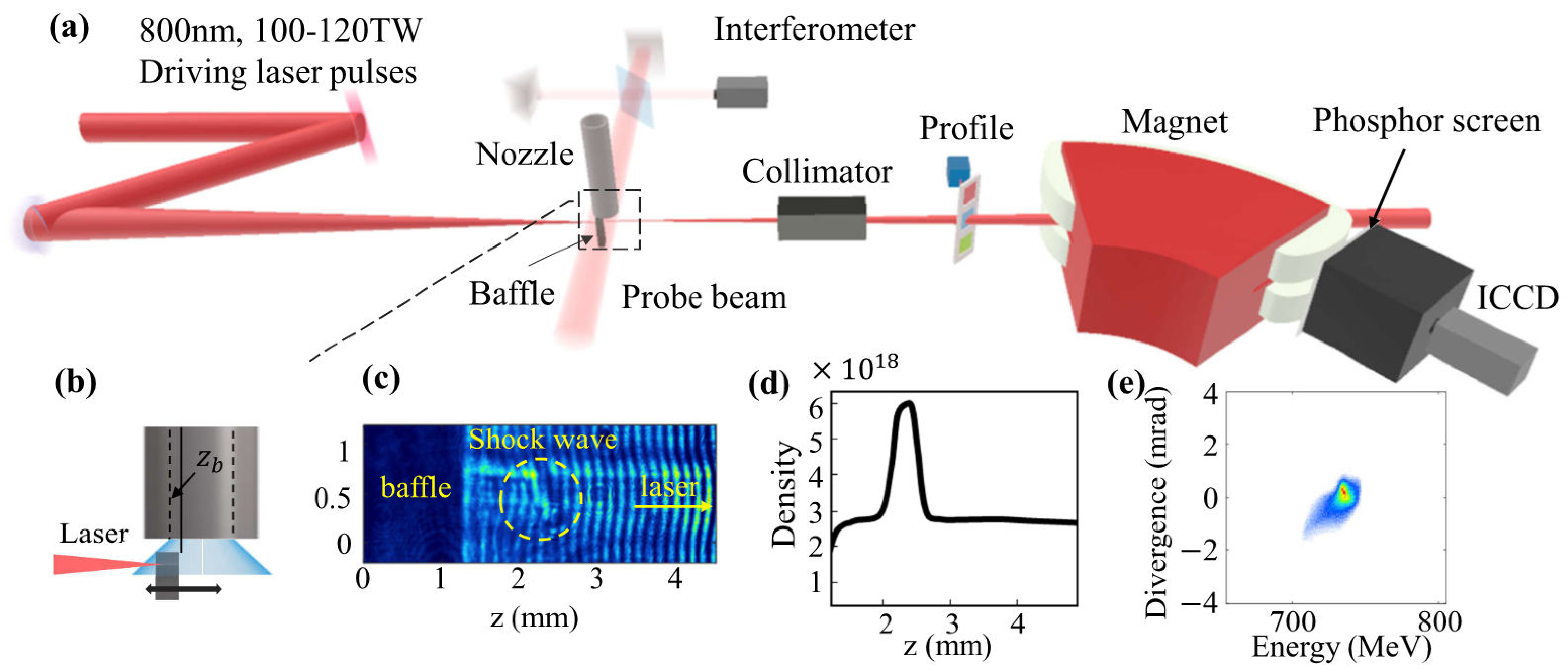
2. Experimental Setup and Experimental Results

The experiments were carried out with a newly built laser facility with a 25-fs pulse duration and 200 TW peak power at 5 Hz based on chirped pulse amplification using Ti:sapphire at SIOM. The energy fluctuation and the pointing stability of the driving laser pulses were optimized to be 0.55% and 1.5 μrad [38], which can be greatly beneficial for the stable and highly repeatable electron beam generation. As shown in Figure 1, the 800-nm laser pulses with an on-target power of 100–120 TW were focused by an f/30 off-axis parabolic mirror onto the gas target. The measured vacuum beam size w 0 was 34 μm at 1/e2. The fractional laser energy contained within the laser spot was measured to be ∼62.1% at 1/e2, and the peak intensity was estimated to be 2.9 3.6 × 10 18   W / cm 2 , corresponding to a normalized amplitude of a 0 1.2 1.3 . A probe beam split from the main laser beam was sent perpendicularly across the gas target, which covered the lower part of the nozzle and the upper part of the baffle, as shown in Figure 1a,b. An optical Michelson-type interferometer using a 4f optical imaging system was set up for measuring the plasma density, as shown in Figure 1c,d. The desired density shock front was manipulated with a perforated baffle and a pulsed gas valve connected to a nozzle with a 6-mm bore diameter. Different from the previous structures [32,39,40], a 2.5-mm-thick perforated copper baffle was inserted parallelly along the nozzle in the upstream of the supersonic flow, and could thus produce a slanted shock wave much farther away from the baffle compared with the previous thin blade (i.e., the right wall of the first segment gas cell). This specifically designed structure may also benefit the required evolution of the bubble and electron injections with a larger charge. It acts as a specially designed structure to form the required plasma density distribution with only one gas jet, resulting in less airflow disturbance and more stable abrupt density transitions. The distance between the exit of the baffle and the left inner wall of the nozzle is defined as zb, as shown in Figure 1b, and the structured gas profile with a stable shock wave is induced with different zb by adjusting the horizontal span along the optical axis. The generated e beams were deflected by a 90-cm-long tunable dipole electromagnet with a maximum magnetic field of 1.1 T and measured with a Lanex phosphor screen imaged with an intensified charge-coupled device (ICCD) camera in a single shot (Figure 1e), which was cross-calibrated by using a calibrated imaging plate and an integrating current transformer (ICT) to measure the charge of the e beams [41]. The collimator was used to shield the low-energy and large-divergence e beams and to minimize the irrelevant signal on the profile during the measurement [4,27,37]. The energy spectrometer had a resolution of 0.2% at 800 MeV and 0.1 mrad divergence, and the uncertainty of the measured peak energy was calculated as ±2% considering the e beam’s pointing stability of 1 mrad. The uncertainty of the measured e beam charge was estimated to be within ±6%.
In the experiment, a comprehensive tuning process for generating bright e beams was explored elaborately by presenting the baffle at different locations. Initially, the baffle was placed beneath the nozzle (zb > 2.5 mm) and the laser was focused at the exit of the baffle; no accelerated e beams were measured in this case when operating the plasma profile with an average density of 2.6 ± 0.5 × 10 18 cm 3 , which is lower than the plasma density for self-injection. By moving the baffle backward to the upstream of the gas jet, continuously injected e beams started to appear. When the coverage rate of the baffle over the nozzle was around 12%, which is much smaller than those in [39,40], a relatively large divergence of ~1.1 mrad and energy spread of 11.2% were measured for the continuously injected electrons, as shown for case 1 in Figure 2a. The following cases in Figure 2a show shadowgraphs and corresponding typical spectra of e beams while moving the baffle backward from zb = 750 μm to zb = 350 μm at a step size of 50 μm. It was observed that when moving the baffle backward, the shock wave approached the baffle and the tilt angle between the shock wave and the baffle decreased from 45° to 33°, but would not affect the electron injection due to the tilt angle, as in [4]. For zb = 450 μm, the generated e beams were already optimized to low-energy spreads of 0.5% and small divergences of 0.25 mrad. As the baffle moved to zb < 450 μm, no e beams were measured over the whole energy spectrum, which indicated that the electron injection did not occur.
The overall properties of the e beams with different plasma-density modulations were measured and are plotted in Figure 2b,c in terms of peak energy, charge, relative energy spread (RES), divergence, and reproducibility. As seen, the peak energy of e beams increased almost linearly from 400 to 800 MeV, and the RES accordingly decreased from 9.7% to 0.5%. The divergences of the e beams decreased from 1 to 0.25 mrad, and the reproducibility accordingly decreased from 100% to 85% for zb = 450 μm. It was also found that for zb = 500 μm, the reproducibility of the measured electron beams was measured to be 95% in a series of 100 continuous shots. The measured average peak energy, root-mean square(rms) energy spread, charge, and divergence were 730 MeV, 0.9%, 34 pC, and 0.3 mrad, respectively. Assuming reasonable values of the e beam size and the pulse duration at the exit of the LWFA as 2 μm and 2.5 fs (FWHM) [42,43,44], backed by the PIC simulations, the produced bright beams could be estimated to have a brightness of ~ 10 15   A / m 2 / 0.1 % [27].

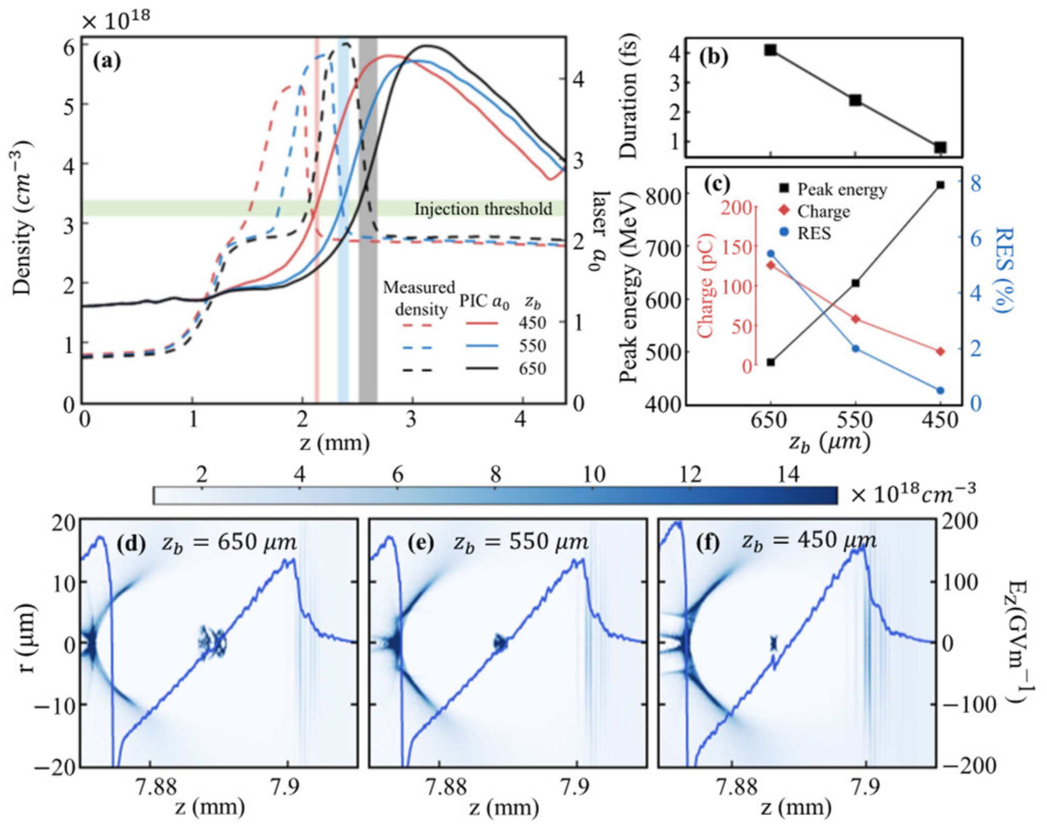
3. Simulation Results

In order to gain more insight into the underlying physics of the electron injection and acceleration process for the different plasma-density modulations, three-dimensional PIC simulations were performed with the FBPIC code [45,46]. The parameters used matched the experimental measurement results. The longitudinal and transverse window sizes were 50 and 120 μm, respectively. The grid cell size was as Δ z = 40 nm and Δ r = 120   nm. A linearly polarized laser pulse with a Gaussian function with a wavelength of λ 0 = 0.8   μ m , normalized amplitude of a0 = 1.24, pulse duration of τ = 25 fs, and spot size of ω0 = 40 μm was launched from the left boundary of the simulation box along the z axis and focused at 1.4 mm behind the entrance of the plasma.
For better understanding, we focus on three different cases of baffle positions: zb = 450, 550, and 650 μm, corresponding to the aforementioned cases 6, 4, and 2 in Figure 2a. The locally magnified density profiles in the measurements around the shock wave are plotted in Figure 3a, and the simulated plasma profile has beenchosen to fit the measured one. For these three cases, the abrupt density transitions induced by shock waves can all help injecting electrons into the wakes once the laser focuses to reach the injection threshold near a 0 = 2.4. In fact, the different plasma-density modulations, as well as the evolution of the self-focusing of the laser, contribute to the various durations of the injected e beams in the PIC simulations, which may actually be contributed by both the density transition and conventional wavebreaking. As the density bump moved forward, a stronger density singularity at the rear of the bubble took shape and more electrons were injected with a higher charge and a larger energy spread. A relatively earlier electron injection at the down-ramp will make the injected electrons move away from the rear of the bubble to the center part more quickly, and they will thus experience a shorter dephasing length and relatively smaller gradient field. Meanwhile, e beams with a larger charge of ~100 pC caused by the later injection at the subsequent down-ramp, which further reduces the local accelerating field for the non-negligible beam-loading effect [47,48], usually have a lower peak energy due to the lower energy gain, as shown in Figure 2a. For this term, the e beams can thus be well tuned and optimized according to the actual demands. As seen in Figure 3b,c, the trends of the duration, peak energy, RES, and charge for these cases demonstrated the robust optimization process and its own advantages in this scheme.
As shown in Figure 3, the e beams have different longitudinal characteristics and durations, as the injection periods vary among the cases, which are presented in the shaded areas at different injection positions. For the simulation case of zb = 450 μm, the bright e beam with a shorter duration of less than 1 fs can be produced with a brightness of ~ 3 × 10 15   A / m 2 / 0.1 % . Compared with our previous work [27,37] based on the cascaded acceleration, in which e beams were injected from the second bubble into the first bubble to realize further acceleration, these e beams were injected and accelerated in the first bubble in this scheme. Using this specific plasma-density profile, the density plateau and up-ramp before the peak of the density profile offer an appropriate evolution of the self-focusing of the laser to increase its intensity and the amplitude of the driven wake. In close proximity to the injection threshold, the transient decrease in the wake phase occurs, and the injection only occurs near the end of the density down-ramp, resulting in a very localized injection and, thus, formation of an e beam with an ultrashort length. For a certain point, this may be used to tune the injection and the duration length of the injected e beam, which may be approximated as the one in [36], indicating that the injection of ultrashort bunches with attosecond durations is possible here.
The overall evolution of the laser pulse is plotted in Figure 4a for the case of zb = 450 μm, where the laser’s evolution in the presented plasma density has played an important role in keeping the energy spread at the per-mille level. As shown in Figure 4b, the defocusing of the laser induced the contraction of the bubble and the transformation of the accelerating field from a highly nonlinear type to a sawtooth-like type. With a proper injection phase, the accelerated e beam could gradually slip back into the rear of the bubble from the positive-slope accelerating field to the negative one. The chirp of the e beam, which would be positive due to the highly nonlinear accelerating field, would be mitigated during this process, as shown in Figure 4c. The whole evolution of the relative and absolute energy spread is included in Figure 4d, which indicates that the dechirping process benefits the low energy spread in this scheme (the underlying physics will be explained in more detail in a separate publication in the future). As observed, the bright e beam with a peak energy of 821 MeV, a peak current of 8 kA, and an rms energy spread of 0.5% can be achieved, which is in good agreement with the measured one.

4. Conclusions

In conclusion, we have experimentally realized a feasible and effective scheme by adjusting the shock wave to control electron injection and acceleration, as well as to optimize e beams with a high reproducibility. In both the experiments and simulations, the e beam’s energy could be tuned by just moving the baffle, and it retained its high quality in terms of its energy spread, charge, and divergence. The resulting simulations repeated the experimental measurements and indicated that this scheme has the potential to produce bright attosecond electron beams. It is believed that these reproducible and tunable bright electron beams in an LWFA can facilitate practical applications for their advancement, especially as radiation sources, such as free-electron lasers and high-energy, bright X-ray sources.

Author Contributions

Conceptualization, L.K. and C.Y.; Methodology, L.K., C.Y., K.F., and W.W.; Validation, W.W. and J.L.; Investigation, L.K.; Software: L.K. and Z.Q.; Experiments—manipulation, L.K., K.F., K.J., H.W., C.Y., W.W., and S.L.; Experiments—laser source, X.Y., Y.X., and Y.L.; Funding acquisition, C.Y., W.W., J.L., and R.L.; Writing—original draft preparation, L.K.; Writing—review and editing, C.Y. and J.L. All authors have read and agreed to the published version of the manuscript.

Funding

This research was funded by the National Natural Science Foundation of China (Grant No. 11991072, 11904377, 11875065, 11974251, and 11127901), the National Key Laboratory of Shock Wave and Detonation Physics (No. 6142A03182011), the CAS Youth Innovation Promotion Association (Y201952), the Shanghai Sailing Program (Grant No. 18YF1426000), the Natural Science Foundation of Shanghai (No. 18JC1414800 and 18ZR1444500), and the Strategic Priority Research Program (B) (Grant No. XDB16).

Institutional Review Board Statement

Not applicable.

Informed Consent Statement

Not applicable.

Data Availability Statement

Not applicable.

Conflicts of Interest

The authors declare no conflict of interest.

References

  1. Feng, K.; Yu, C.; Liu, J.; Wang, W.; Tian, Y.; Zhang, Z.; Qi, R.; Fang, M.; Liu, J.; Qin, Z.; et al. Coherent X-ray source generation with off-resonance laser modulation. Opt. Express 2018, 26, 19067–19079. [Google Scholar] [CrossRef]
  2. Allaria, E.; Castronovo, D.; Cinquegrana, P.; Craievich, P.; Dal Forno, M.; Danailov, M.B.; D’Auria, G.; Demidovich, A.; De Ninno, G.; Di Mitri, S.; et al. Two-stage seeded soft-X-ray free-electron laser. Nat. Photonics 2013, 7, 913–918. [Google Scholar] [CrossRef]
  3. Corde, S.; Ta Phuoc, K.; Lambert, G.; Fitour, R.; Malka, V.; Rousse, A.; Beck, A.; Lefebvre, E. Femtosecond x rays from laser-plasma accelerators. Rev. Mod. Phys. 2013, 85, 1–48. [Google Scholar] [CrossRef]
  4. Yu, C.; Liu, J.; Wang, W.; Li, W.; Qi, R.; Zhang, Z.; Qin, Z.; Liu, J.; Fang, M.; Feng, K.; et al. Enhanced betatron radiation by steering a laser-driven plasma wakefield with a tilted shock front. Appl. Phys. Lett. 2018, 112, 133503. [Google Scholar] [CrossRef] [Green Version]
  5. Giulietti, A. Laser-Driven Particle Acceleration towards Radiobiology and Medicine; Springer: Berlin/Heidelberg, Germany, 2016. [Google Scholar]
  6. Cole, J.M.; Wood, J.C.; Lopes, N.C.; Poder, K.; Abel, R.L.; Alatabi, S.; Bryant, J.S.; Jin, A.; Kneip, S.; Mecseki, K.; et al. Laser-wakefield accelerators as hard x-ray sources for 3D medical imaging of human bone. Sci. Rep. 2015, 5, 13244. [Google Scholar] [CrossRef]
  7. Banerjee, S.; Kalmykov, S.Y.; Powers, N.D.; Golovin, G.; Ramanathan, V.; Cunningham, N.J.; Brown, K.J.; Chen, S.; Ghebregziabher, I.; Shadwick, B.A.; et al. Stable, tunable, quasimonoenergetic electron beams produced in a laser wakefield near the threshold for self-injection. Phys. Rev. ST Accel. Beams 2013, 16, 031302. [Google Scholar] [CrossRef] [Green Version]
  8. Kuschel, S.; Schwab, M.B.; Yeung, M.; Hollatz, D.; Seidel, A.; Ziegler, W.; Savert, A.; Kaluza, M.C.; Zepf, M. Controlling the Self-Injection Threshold in Laser Wakefield Accelerators. Phys. Rev. Lett. 2018, 121, 154801. [Google Scholar] [CrossRef] [Green Version]
  9. Martinez de la Ossa, A.; Grebenyuk, J.; Mehrling, T.; Schaper, L.; Osterhoff, J. High-quality electron beams from beam-driven plasma accelerators by wakefield-induced ionization injection. Phys. Rev. Lett. 2013, 111, 245003. [Google Scholar] [CrossRef] [Green Version]
  10. Li, F.; Hua, J.F.; Xu, X.L.; Zhang, C.J.; Yan, L.X.; Du, Y.C.; Huang, W.H.; Chen, H.B.; Tang, C.X.; Lu, W.; et al. Generating high-brightness electron beams via ionization injection by transverse colliding lasers in a plasma-wakefield accelerator. Phys. Rev. Lett. 2013, 111, 015003. [Google Scholar] [CrossRef] [PubMed] [Green Version]
  11. Mirzaie, M.; Li, S.; Zeng, M.; Hafz, N.A.; Chen, M.; Li, G.Y.; Zhu, Q.J.; Liao, H.; Sokollik, T.; Liu, F.; et al. Demonstration of self-truncated ionization injection for GeV electron beams. Sci. Rep. 2015, 5, 14659. [Google Scholar] [CrossRef] [PubMed] [Green Version]
  12. Irman, A.; Couperus, J.P.; Debus, A.; Köhler, A.; Krämer, J.M.; Pausch, R.; Zarini, O.; Schramm, U. Improved performance of laser wakefield acceleration by tailored self-truncated ionization injection. Plasma Phys. Control. Fusion 2018, 60, 044015. [Google Scholar] [CrossRef]
  13. Silva, T.; Helm, A.; Vieira, J.; Fonseca, R.; Silva, L.O. On the use of the envelope model for down-ramp injection in laser-plasma accelerators. Plasma Phys. Control. Fusion 2020, 62, 024001. [Google Scholar] [CrossRef]
  14. Ekerfelt, H.; Hansson, M.; Gallardo Gonzalez, I.; Davoine, X.; Lundh, O. A tunable electron beam source using trapping of electrons in a density down-ramp in laser wakefield acceleration. Sci. Rep. 2017, 7, 12229. [Google Scholar] [CrossRef] [PubMed] [Green Version]
  15. Chen, M.; Esarey, E.; Geddes, C.G.R.; Cormier-Michel, E.; Schroeder, C.B.; Bulanov, S.S.; Benedetti, C.; Yu, L.L.; Rykovanov, S.; Bruhwiler, D.L.; et al. Electron injection and emittance control by transverse colliding pulses in a laser-plasma accelerator. Phys. Rev. ST Accel. Beams 2014, 17. [Google Scholar] [CrossRef] [Green Version]
  16. Gonsalves, A.J.; Nakamura, K.; Daniels, J.; Benedetti, C.; Pieronek, C.; De Raadt, T.C.H.; Steinke, S.; Bin, J.H.; Bulanov, S.S.; Van Tilborg, J.; et al. Petawatt Laser Guiding and Electron Beam Acceleration to 8 GeV in a Laser-Heated Capillary Discharge Waveguide. Phys. Rev. Lett. 2019, 122, 084801. [Google Scholar] [CrossRef] [Green Version]
  17. Debus, A.; Pausch, R.; Huebl, A.; Steiniger, K.; Widera, R.; Cowan, T.E.; Schramm, U.; Bussmann, M. Circumventing the Dephasing and Depletion Limits of Laser-Wakefield Acceleration. Phys. Rev. X 2019, 9, 031044. [Google Scholar] [CrossRef] [Green Version]
  18. Palastro, J.P.; Shaw, J.L.; Franke, P.; Ramsey, D.; Simpson, T.T.; Froula, D.H. Dephasingless Laser Wakefield Acceleration. Phys. Rev. Lett. 2020, 124, 134802. [Google Scholar] [CrossRef]
  19. Caizergues, C.; Smartsev, S.; Malka, V.; Thaury, C. Phase-locked laser-wakefield electron acceleration. Nat. Photonics 2020, 14, 475–749. [Google Scholar] [CrossRef]
  20. Tomassini, P.; Terzani, D.; Baffigi, F.; Brandi, F.; Fulgentini, L.; Koester, P.; Labate, L.; Palla, D.; Gizzi, L.A. High-quality 5 GeV electron bunches with resonant multi-pulse ionization injection. Plasma Phys. Control. Fusion 2020, 62, 014010. [Google Scholar] [CrossRef]
  21. Zhang, Z.; Li, W.; Liu, J.; Wang, W.; Yu, C.; Tian, Y.; Nakajima, K.; Deng, A.; Qi, R.; Wang, C.; et al. Energy spread minimization in a cascaded laser wakefield accelerator via velocity bunching. Phys. Plasmas 2016, 23, 053106. [Google Scholar] [CrossRef]
  22. Brinkmann, R.; Delbos, N.; Dornmair, I.; Kirchen, M.; Assmann, R.; Behrens, C.; Floettmann, K.; Grebenyuk, J.; Gross, M.; Jalas, S.; et al. Chirp Mitigation of Plasma-Accelerated Beams by a Modulated Plasma Density. Phys. Rev. Lett. 2017, 118, 214801. [Google Scholar] [CrossRef] [PubMed] [Green Version]
  23. Wu, Y.P.; Hua, J.F.; Zhou, Z.; Zhang, J.; Liu, S.; Peng, B.; Fang, Y.; Nie, Z.; Ning, X.N.; Pai, C.H.; et al. Phase Space Dynamics of a Plasma Wakefield Dechirper for Energy Spread Reduction. Phys. Rev. Lett. 2019, 122, 204804. [Google Scholar] [CrossRef] [PubMed] [Green Version]
  24. Manahan, G.G.; Habib, A.F.; Scherkl, P.; Delinikolas, P.; Beaton, A.; Knetsch, A.; Karger, O.; Wittig, G.; Heinemann, T.; Sheng, Z.M.; et al. Single-stage plasma-based correlated energy spread compensation for ultrahigh 6D brightness electron beams. Nat. Commun. 2017, 8, 15705. [Google Scholar] [CrossRef] [PubMed]
  25. D’Arcy, R.; Wesch, S.; Aschikhin, A.; Bohlen, S.; Behrens, C.; Garland, M.J.; Goldberg, L.; Gonzalez, P.; Knetsch, A.; Libov, V.; et al. Tunable Plasma-Based Energy Dechirper. Phys. Rev. Lett. 2019, 122, 034801. [Google Scholar] [CrossRef] [Green Version]
  26. Dopp, A.; Thaury, C.; Guillaume, E.; Massimo, F.; Lifschitz, A.; Andriyash, I.; Goddet, J.P.; Tazfi, A.; Ta Phuoc, K.; Malka, V. Energy-Chirp Compensation in a Laser Wakefield Accelerator. Phys. Rev. Lett. 2018, 121, 074802. [Google Scholar] [CrossRef] [Green Version]
  27. Wang, W.T.; Li, W.T.; Liu, J.S.; Zhang, Z.J.; Qi, R.; Yu, C.H.; Liu, J.Q.; Fang, M.; Qin, Z.Y.; Wang, C.; et al. High-Brightness High-Energy Electron Beams from a Laser Wakefield Accelerator via Energy Chirp Control. Phys. Rev. Lett. 2016, 117, 124801. [Google Scholar] [CrossRef] [PubMed]
  28. Xu, X.L.; Li, F.; An, W.; Dalichaouch, T.N.; Yu, P.; Lu, W.; Joshi, C.; Mori, W.B. High quality electron bunch generation using a longitudinal density-tailored plasma-based accelerator in the three-dimensional blowout regime. Phys. Rev. ST Accel. Beams 2017, 20, 111303. [Google Scholar] [CrossRef] [Green Version]
  29. Guénot, D.; Gustas, D.; Vernier, A.; Beaurepaire, B.; Böhle, F.; Bocoum, M.; Lozano, M.; Jullien, A.; Lopez-Martens, R.; Lifschitz, A.; et al. Relativistic electron beams driven by kHz single-cycle light pulses. Nat. Photonics 2017, 11, 293–296. [Google Scholar] [CrossRef] [Green Version]
  30. He, Z.H.; Hou, B.; Nees, J.A.; Easter, J.H.; Faure, J.; Krushelnick, K.; Thomas, A.G.R. High repetition-rate wakefield electron source generated by few-millijoule, 30 fs laser pulses on a density downramp. New J. Phys. 2013, 15. [Google Scholar] [CrossRef]
  31. Maier, A.R.; Delbos, N.M.; Eichner, T.; Hübner, L.; Jalas, S.; Jeppe, L.; Jolly, S.W.; Kirchen, M.; Leroux, V.; Messner, P.; et al. Decoding Sources of Energy Variability in a Laser-Plasma Accelerator. Phys. Rev. X 2020, 10, 031039. [Google Scholar] [CrossRef]
  32. Buck, A.; Wenz, J.; Xu, J.; Khrennikov, K.; Schmid, K.; Heigoldt, M.; Mikhailova, J.M.; Geissler, M.; Shen, B.; Krausz, F.; et al. Shock-front injector for high-quality laser-plasma acceleration. Phys. Rev. Lett. 2013, 110, 185006. [Google Scholar] [CrossRef] [PubMed]
  33. Fang, M.; Zhang, Z.; Wang, W.; Liu, J.; Li, R. Sharp plasma pinnacle structure based on shockwave for an improved laser wakefield accelerator. Plasma Phys. Control. Fusion 2018, 60, 075008. [Google Scholar] [CrossRef]
  34. Bulanov, S.; Naumova, N.; Pegoraro, F.; Sakai, J. Particle injection into the wave acceleration phase due to nonlinear wake wave breaking. Phy. Rev. E 1998, 58, R5257. [Google Scholar] [CrossRef] [Green Version]
  35. Thompson, M.C.; Rosenzweig, J.B.; Suk, H. Plasma density transition trapping as a possible high-brightness electron beam source. Phys. Rev. ST Accel. Beams 2004, 7, 011301. [Google Scholar] [CrossRef] [Green Version]
  36. Tooley, M.P.; Ersfeld, B.; Yoffe, S.R.; Noble, A.; Brunetti, E.; Sheng, Z.M.; Islam, M.R.; Jaroszynski, D.A. Towards Attosecond High-Energy Electron Bunches: Controlling Self-Injection in Laser-Wakefield Accelerators Through Plasma-Density Modulation. Phys. Rev. Lett. 2017, 119, 044801. [Google Scholar] [CrossRef] [Green Version]
  37. Yu, C.; Qi, R.; Wang, W.; Liu, J.; Li, W.; Wang, C.; Zhang, Z.; Liu, J.; Qin, Z.; Fang, M.; et al. Ultrahigh brilliance quasi-monochromatic MeV gamma-rays based on self-synchronized all-optical Compton scattering. Sci. Rep. 2016, 6, 29518. [Google Scholar] [CrossRef] [PubMed] [Green Version]
  38. Wu, F.; Zhang, Z.; Yang, X.; Hu, J.; Ji, P.; Gui, J.; Wang, C.; Chen, J.; Peng, Y.; Liu, X.; et al. Performance improvement of a 200TW/1Hz Ti:sapphire laser for laser wakefield electron accelerator. Opt. Laser Technol. 2020, 131, 106453. [Google Scholar] [CrossRef]
  39. Swanson, K.K.; Tsai, H.E.; Barber, S.K.; Lehe, R.; Mao, H.S.; Steinke, S.; Van Tilborg, J.; Nakamura, K.; Geddes, C.G.R.; Schroeder, C.B.; et al. Control of tunable, monoenergetic laser-plasma-accelerated electron beams using a shock-induced density downramp injector. Phys. Rev. Accel. Beams 2017, 20, 051301. [Google Scholar] [CrossRef] [Green Version]
  40. Tsai, H.-E.; Swanson, K.K.; Barber, S.K.; Lehe, R.; Mao, H.-S.; Mittelberger, D.E.; Steinke, S.; Nakamura, K.; Van Tilborg, J.; Schroeder, C.; et al. Control of quasi-monoenergetic electron beams from laser-plasma accelerators with adjustable shock density profile. Phys. Plasmas 2018, 25, 043107. [Google Scholar] [CrossRef] [Green Version]
  41. Bonnet, T.; Comet, M.; Denis-Petit, D.; Gobet, F.; Hannachi, F.; Tarisien, M.; Versteegen, M.; Aleonard, M.M. Response functions of imaging plates to photons, electrons and 4He particles. Rev. Sci. Instrum. 2013, 84, 103510. [Google Scholar] [CrossRef]
  42. Lundh, O.; Lim, J.; Rechatin, C.; Ammoura, L.; Ben-Ismaïl, A.; Davoine, X.; Gallot, G.; Goddet, J.P.; Lefebvre, E.; Malka, V.; et al. Few femtosecond, few kiloampere electron bunch produced by a laser–plasma accelerator. Nat. Phys. 2011, 7, 219–222. [Google Scholar] [CrossRef] [Green Version]
  43. Ta Phuoc, K.; Corde, S.; Thaury, C.; Malka, V.; Tafzi, A.; Goddet, J.P.; Shah, R.C.; Sebban, S.; Rousse, A. All-optical Compton gamma-ray source. Nat. Photonics 2012, 6, 308–311. [Google Scholar] [CrossRef]
  44. Buck, A.; Nicolai, M.; Schmid, K.; Sears, C.M.S.; Sävert, A.; Mikhailova, J.M.; Krausz, F.; Kaluza, M.C.; Veisz, L. Real-time observation of laser-driven electron acceleration. Nat. Phys. 2011, 7, 543–548. [Google Scholar] [CrossRef] [Green Version]
  45. Lehe, R.; Kirchen, M.; Andriyash, I.A.; Godfrey, B.B.; Vay, J.-L. A spectral, quasi-cylindrical and dispersion-free Particle-In-Cell algorithm. Comput. Phys. Commun. 2016, 203, 66–82. [Google Scholar] [CrossRef] [Green Version]
  46. Jalas, S.; Dornmair, I.; Lehe, R.; Vincenti, H.; Vay, J.L.; Kirchen, M.; Maier, A.R. Accurate modeling of plasma acceleration with arbitrary order pseudo-spectral particle-in-cell methods. Phys. Plasma 2017, 24, 033115. [Google Scholar] [CrossRef] [Green Version]
  47. Katsouleas, T.; Wilks, S.; Chen, P.; Dawson, J.M.; Su, J.J. Beam loading in plasma accelerators. Part. Accel. 1987, 22, 81–99. [Google Scholar]
  48. Tzoufras, M.; Lu, W.; Tsung, F.S.; Huang, C.; Mori, W.B.; Katsouleas, T.; Vieira, J.; Fonseca, R.A.; Silva, L.O. Beam loading in the nonlinear regime of plasma-based acceleration. Phys. Rev. Lett. 2008, 101, 145002. [Google Scholar] [CrossRef] [PubMed] [Green Version]
Figure 1. (a) Schematic of the experimental setup. (b) The diagram of the magnified nozzle and baffle assembly. The driving laser pulse can pass through the hole of the baffle and interact with the gas target to form the plasma. The baffle can be moved forward (along the propagation direction of the laser, i.e., from left to right) or backward (against the propagation direction of the laser) along the optical axis at a minimal step size of 5 μm. (c) The fringe pattern retrieved from the interferometer. The shock wave is circled with a dashed line. (d) The density profile along the optical axis. (e) A typical and represented spectrum of an e beam that has an energy peak at 730 MeV.
Applsci 11 02560 g001
Figure 2. (a) The typical shadowgraphs of the baffle and the shock wave when the baffle moved backward (from right to left) at a step size of 50 μm. In each case, the shadowgraph ranged from the middle of the baffle. The position of the baffle at each case was marked aside. The right part shows the measured typical spectra of e beams that correspond to cases 1 to 8. (b,c) The characteristic properties of e beams at different zb; all the points are averages of values measured over 100 shots. The orange bar chart in (b) represents the reproducibility of the e beams.
Applsci 11 02560 g002
Figure 3. (a) The measured density distributions (dashed line) and the evolutions of the normalized laser intensity (solid line) in the PIC simulations for baffle positions of zb = 450 (red), 550 (blue), and 650 μm (black). As the baffle moved toward the nozzle, the shock wave also moved forward and had a higher peak. The electron injection process is shown by the shaded area, which occurred once the general injection threshold of a 0 ~2.4, marked by the green shaded area, was reached. (b,c) The corresponding pulse duration, peak energy, charge, and RES of e beams for different cases. (df) Snapshots of the laser-driven plasma electron distribution in the r-z plane for the three cases at the same time.
Applsci 11 02560 g003
Figure 4. (a) The evolution of the transverse beam intensity along the laser propagation for z b = 450   μ m. The self-focusing process of the laser can be identified. (b) Demonstration of a snapshot of electron density distribution in the r-z plane for z = 3.8 mm and the on-axis plasma field lineouts (blue line) in the PIC simulation. (c) The schematic of a dechirping process. The chirps of e beams at different propagation distances are marked with dashed lines. Shaped areas show the spectra of corresponding e beams at different z. (d) The evolution of the peak energy, the RES, and the absolute energy spread (AES) with respect to the propagation distance.
Applsci 11 02560 g004
Publisher’s Note: MDPI stays neutral with regard to jurisdictional claims in published maps and institutional affiliations.

