Article

Theoretical Investigation on Performance Characteristics of Aerostatic Journal Bearings with Active Displacement Compensator

Polytechnic Institute, Siberian Federal University, 660079 Krasnoyarsk, Russia
*
Author to whom correspondence should be addressed.
Appl. Sci. 2021, 11(6), 2623; https://doi.org/10.3390/app11062623
Submission received: 16 February 2021 / Revised: 4 March 2021 / Accepted: 9 March 2021 / Published: 16 March 2021

Abstract

:
Active aerostatic bearings are capable of providing negative compliance, which can be successfully used to automatically compensate for deformation of the machine tool system in order to reduce the time and improve the quality of metalworking. The article considers an aerostatic radial bearing with external combined throttling systems and an elastic displacement compensator, which is an alternative to aerostatic bearings with air flow rate compensators. The results of the mathematical modeling and theoretical research of stationary and nonstationary modes of operation of bearings with slotted and diaphragm throttling systems are presented. A counter-matrix sweep method has been developed for solving linear and nonlinear boundary value problems in partial derivatives with respect to the function of the square of the pressure in the bearing gap and inter-throttling bearing cavities for any values of the relative shaft eccentricity. A numerical method is proposed for calculating the dynamic quality criteria, and the transfer function of the dynamic compliance of a bearing with small displacements is considered as a linear automatic control system with distributed parameters. An experimental verification of the theoretical characteristics of the bearing was carried out, which showed a satisfactory correspondence among the compared data. It is shown that bearings with a throttle system have the best quantitative and qualitative load characteristics. The possibility of optimal determination of the values of a number of important parameters that provide the bearing with optimal performance and a high stability margin is established. It is shown that bearings with an elastic suspension of the movable sleeve allow one to compensate for significant movements, which can be larger than the size of the air gap by an order of magnitude or more. In these conditions, similar bearings with air flow compensators would be obviously inoperative.

1. Introduction

Aerostatic bearings are used in precision machine tool spindles. Their use is attractive, with minimal friction losses, high durability, and environmental friendliness. Unlike hydrostatic bearings, they minimize the difficulties associated with the supply and return of air lubricant [1,2,3,4].
A typical disadvantage of aerostatic bearings is their high compliance and low bearing capacity due to limited supply pressure [5,6]. To reduce compliance, improved designs are used, which, according to the principle of operation, can be divided into bearings with active compensation of air flow rate and active compensation of the moving element (shaft) displacement. These types of bearings allow for a decrease in compliance to zero and even negative values (in the latter case, the shaft is displaced in the direction opposite to the current load relative to the housing), which allows the structures to be used not only as supports but, also, as active deformation compensators of the machine tools’ technological system (TS) in order to reduce the time and improve the accuracy of metalworking.
In bearings with active flow rate compensation (AFC), variable resistance throttles are used, which include membrane compensators and elastic orifices that can change their resistance depending on the pressure drop [7,8,9,10,11,12,13,14,15]. These constructions have been studied in sufficient detail. Their disadvantage is a significant air flow rate, which is necessary to ensure negative compliance. In addition, they are able to compensate for the deformation of the vehicle only in a narrow range limited by the size of the working gap, which is 5–20 μm. This is often not enough to exclude the negative effect of a TS deformation.
In this respect, the relatively poorly studied aerostatic bearings with active displacement compensation (ADC) have the best prospects [16,17,18,19]. Their use makes it possible to compensate for significantly larger displacements, whose magnitude can exceed the AFC’s by an order or more, while, as studies show, bearings with ADC are less energy-intensive [16,18]. In theoretical terms, the operation of such bearings was investigated only for the mode of small shaft deviation from its central position [16,17]. This is due to the fact that the modes of arbitrary position of the moving elements of the bearing are described by nonlinear mathematical models containing one or more partial differential equations, which creates significant difficulties for the development of effective algorithms for calculating the performance of the structure. Currently, there are no studies on the operation of bearings at moderate, high and ultimate loads on bearings with ADC, as well as the influence of the configuration of the bearing gap and types of flow restrictors on their performance—in particular, on the possibility and prospects of increasing their load capacity.
In this paper, we consider the design of a radial aerostatic bearing with a displacement compensator and various feeder options—slots and diaphragms. The design is equipped with a system of external combined throttling (SECT), which allows the bearing to provide satisfactory dynamic properties when operating at low, zero and negative compliance modes. A mathematical model of the static state of the bearing is proposed, and methods and algorithms are developed for calculating the load capacity and compliance of a bearing with an arbitrary eccentricity of the shaft and support sleeve. A model of the dynamic state of the structure is formulated, and the criteria for its dynamic quality are calculated.

2. Bearing Design and Principle of its Operation

Consider a radial aerostatic bearing (Figure 1a), which consists of a shaft (1), a housing (2) and a movable inner sleeve (3), resting on an elastic suspension (6). In the housing (2), there are throttling feeders (4), and in the movable sleeve (3), there are damping feeders (5), whose resistance in a stable bearing should be about an order of magnitude lower than the resistance of feeders (4) [14]. The surfaces of the housing, bushing and elastic suspension form inter-throttle chambers (7), whose volume plays a significant role in ensuring an acceptable dynamic quality of the structure. The elastic suspension has the ability to resist deformation under the action of pressure forces on the surfaces of the sleeve (3). To reduce the negative effect of the circumferential air flow in the inter-throttle cavities for the load characteristics of the bearing, they are separated from each other by a sufficient number of longitudinal baffles, as shown in Figure 1b.
Compressed air under supply pressure ps = const (the pressure source is not shown in Figure 1), overcoming the resistance of throttling feeders (4), enters the inter-throttling cavities (7) of the volume vp under pressure pp < ps. Further, through damping feeders (5), air enters the bearing gap under pressure pk < pp and then flows out into the environment with pressure pa. An increase or decrease in the load f on the bearing, respectively, increases or decreases the pressures pk and pp in the loaded area and decreases or increases in the unloaded area of the bearing gap.
Figure 1. Design diagram of a radial aerostatic bearing with displacement compensator. (a) Longitudinal section, (b) suspension unfold drawing.
Applsci 11 02623 g001
Under the action of the force reactions of compressed air, elastic deformation of the suspension (6) occurs, causing displacement ep of the sleeve (3) in the direction opposite to f. In this case, the displacement of the shaft (1) relative to the body (2) will be of the total value es = ep + e, where e and ep are the eccentricities of the shaft (1) and the sleeve (3). At es = 0, the bearing will have zero compliance (infinite stiffness) and, at es < 0, negative. With the correct determination of the elasticity of the suspension (6) and other bearing parameters, it is possible to provide any necessary compliance of the bearing gas gap, as shown for the thrust bearings in references [16,20,21].

3. Linear Mathematical Model of the Bearing Stationary State

In a stationary mode, we consider small radial oscillations of the shaft (1), caused by the small effects of an external load f. The study of this state is necessary to determine the optimal stationary compliance modes of a lightly loaded bearing and to verify the characteristics of a nonlinear stationary model using specific examples.
When using diaphragms, we will assume that the number of feeders in each row is large enough to calculate the bearing using the method of continuous pressurization lines, which allows replacing discrete pressurization holes in each row with an equivalent continuous feeder of constant pressure while maintaining the nature of lubricant flow from simple or annular diaphragms [22]. This approach simplifies the mathematical modeling of the bearing without any noticeable deterioration in the accuracy of calculating its characteristics [23,24].
The study of the static and dynamic characteristics of the bearing was carried out in a dimensionless form. The following are taken as scales of values: shaft radius r0—for lengths, radii and longitudinal coordinate z; the thickness h0 of the lubricating gap at the coaxial arrangement of the shaft and the sleeve—for the current thickness h of the gap and eccentricities e, ep and es; ambient pressure pa—for pressures; 2πr02pa—for forces; h 0 3 p a 2 12 μ T —for mass air flow rates, where μ is the dynamic viscosity of air, is the gas constant and T is the absolute air temperature.

3.1. Boundary Value Problems for a Dimensionless Function of Pressure in the Bearing Gap

When the axes of the shaft (1) and the sleeve (3) are parallel, and the pressure function P(Z,φ) in the bearing gap satisfies the stationary Reynolds equation [25]:
φ ( H 3 P P φ ) + Z ( H 3 P P Z ) = 0 ,
where Z and φ are longitudinal and circumferential coordinates, and
H ( φ ) = 1 ε ( τ ) cos φ ,
is a function of the thickness of the bearing gap and ε—eccentricity.
To formulate the boundary conditions for (1), we introduced the local coordinate systems. We will consider the symmetrical right half of the bearing. In the inter-row part, 0 ≤ ZL1, and, in the end part, 0 ≤ ZL2; for both of these parts, 0 ≤ φ ≤ 2π, where L1 is half the length of the inter-row part, L2 = LL1 is the length of the end parts, L3 is half the length of the throttle chambers, L is half the length of the bearing and R1 is the outer radius of the sleeve (3).
The boundary conditions for half of the inter-row part are
P Z ( 0 , φ ) = 0 , P ( L 1 , φ ) = P k ( φ ) ,
for the end part:
P ( 0 , φ ) = P k ( φ ) , P ( L 2 , φ ) = 1 ,
and for both parts:
P ( Z , φ ) = P ( Z , φ + 2 π ) , P φ ( Z , φ ) = P φ ( Z , φ + 2 π ) ,
where P k ( φ ) is the function of pressure on the injection line at the air outlet from the damping feeders.
The initial condition for (1) is the pressure function P0(Z) with the coaxial position of the shaft and sleeve at ε = 0, no load and no shaft rotation. This function can be found by solving the boundary value problem:
{ d 2 P 0 2 d Z 2 = 0 , d P 0 d Z ( 0 ) = 0 , P 0 ( L 1 ) = P k 0 , P 0 ( 0 ) = P k 0 , P 0 ( L 2 ) = 1 ,
where Pk0 is a constant value equal to the value of the pressure function at the air outlet from the annular diaphragms.

3.2. System of Equations for the Balance of Forces and Air Flow Rates of SECT

The dimensionless system of equations describing the static equilibrium of the bearing includes one equation for forces and two equations for the balance of air flow rates in the SECT:
{ W = F , ε p = K e ( W W p ) , Q p Q k = 0 , Q k Q h = 0 ,
where W, F and Wp are the bearing capacity, external load on the bearing and force reaction of air in chambers (7); εp is dimensionless eccentricity of the housing (2) and sleeve (3); Qp, Qk and Qh are the mass flow rates of air through the main resistance, damping resistance and at the air inlet the bearing gap and Ke is the coefficient of the elasticity (compliance) of the suspension (6).
The bearing capacity is determined by the formula [25]
W = 1 π 0 2 π 0 L ( P 1 ) cos φ d Z d φ .
The components of the equations for the balance of air flow rates (7) are represented by the local functions of the lubricant outflow on arcs of infinitesimal length centered at the current point of the circular coordinate φ.
When modeling the flow of lubricant through the flow path of the bearing, a mathematical model of air movement in an aerostatic support with SECT was used. The dimensionless flow rate through the slot resistances of the SECT is expressed by the formulas [26]
{ Q k = A k ( P p 2 P k 2 ) , Q p = A p ( P s 2 P p 2 ) .
The dimensionless flow rate through the SECT throttles is determined by the formulas [26]
{ Q k = A k H Π ( P p , P k ) , Q p = A p Π ( P s , P p ) ,
where Ps is the dimensionless supply pressure, P p ( φ ) is the function of the dimensionless pressure in the throttle chambers, Π = Π ( P 1 , P 2 ) is the Prandtl function and Ak and Ap are the dimensionless criteria for the similarity of the feeders.
At the outlet of the pressurization line and the inlet into the carrier gap, the dimensionless gas flow rate Qh is distributed in two directions: Qh1 into the inter-row area and Qh2 into the end part:
Q h = Q h 1 Q h 2 ,
where
Q h 1 = H 3 ( P 2 Z ) Z 1 0 ,
Q h 2 = H 3 ( P 2 Z ) Z 1 + 0 .

3.3. Setting the Resistances of SECT

In the absence of load on the bearing with the coaxial arrangement of the shaft and sleeve, Problem (6) has a solution:
P 0 ( Z ) = { P k 0 , 0 Z L 1 , ( P k 0 2 1 ) L 2 Z L 2 + 1 , 0 Z L 2
Using Equations (11)–(13) for this mode at ε = 0, we obtain the local flow rate in the lubricant gap
Q h 0 = P k 0 2 1 L 2 .
It is convenient to calculate the constant static pressure Pk0 at the outlet of the damping feeders and the corresponding pressure Pp0 in the inter-throttling chambers using the normalized coefficients [26]:
χ = P k 0 2 1 P s 2 1 [ 0 , 1 ] , ς = P p 0 2 P k 0 2 P s 2 P k 0 2 [ 0 , 1 ] .
By setting the supply pressure Ps, χ and ς, we can find the dimensionless pressures of the unloaded bearing:
P k 0 = 1 + χ ( P s 2 1 ) , P p 0 = P k 0 2 + ς ( P s 2 P k 0 2 ) .
and flow rate (15).
Using system (7) at ε = 0, taking into account (9), we obtain the criteria for the similarity of the slotted feeders:
A k = Q h 0 P p 0 2 P k 0 2 , A p = Q h 0 P s 2 P p 0 2 ,
and taking into account (10), the similar criteria for the simple and damping throttling annular diaphragms:
A k = Q h 0 Π ( P k 0 , P p 0 ) , A p = Q h 0 Π ( P p 0 , P s ) .

3.4. Linearization of the Stationary Model by the Small Parameter Method

The response to small loads F will be the small changes in the clearance (2) and pressure at the outlet of the feeders:
P k ( φ ) = P k 0 + U k ε cos φ ,
P p ( φ ) = P p 0 + U p ε cos φ ,
where eccentricity ε is a small parameter.
Representing, by analogy, the pressure distributed in the lubricant gap in the form
P ( Z , φ ) = P 0 ( Z ) + U ( Z ) ε cos φ ,
substituting (25) into the boundary value of Problems (1)–(5) and performing its linearization, we obtain the boundary value problem
{ d 2 ( P 0 U ) d Z 2 P 0 U = 0 , d U d Z ( 0 ) = 0 , U ( L 1 ) = U k , 0 Z L 1 , U ( 0 ) = U k , U ( L 2 ) = 0 , 0 Z L 2 .
The solution to Problem (23) is the function
U ( Z ) = { U k ch Z ch L 1 , Z L 1 , P k 0 U k sh ( L 2 Z ) P 0 ( Z ) sh L 2 , Z L 2 .
The bearing capacity is calculated by the formula from [25]
W = 1 π 0 2 π 0 L ( P 1 ) cos φ d Z d φ = 1 π 0 2 π cos 2 φ d φ 0 L U d Z = ε 0 L U ( Z ) d Z .
Substituting (24) into (25), we find
W = A w k U k ε ,
where A w k = th L 1 + P k 0 sh L 1 0 L 2 sh ( L 2 Z ) P 0 ( Z ) d Z .
In the inter-throttle region, the pressure is determined by Formula (21), so the reaction of the pressure forces is
W p = R 1 π 0 2 π 0 L 3 ( P p 1 ) cos φ d Z d φ = A w p U p ε ,
where
A w p = L 3 R 1 .
The flow rate at the inlet to the carrier gap is determined by the formula
Q q = H 3 d P 2 d Z Z = L 1 H 3 d P 2 d Z Z = L 1 +
Performing linearization (28) and substituting (20) and (24) into the resulting expression, we found
Q q = ( A 0 U k A 1 ) ε ,
where
A 0 = 2 P k 0 ( th L 1 + cth L 2 ) , A 1 = 3 L 2 ( P k 0 2 1 ) .
For the slotted feeders, the flow rates determined by Expressions (9) after linearization take the form
{ Q k = ( A 2 U k + A 3 U p A 4 ) ε , Q p = A 5 U p ε ,
where
A 2 = 2 A k P k 0 , A 3 = 2 A k P p 0 , A 4 = 0 , A 5 = 2 A p P p 0 .
For the simple and annular diaphragms, taking into account (10), we obtain
A 2 = A k Π ( P p 0 , P k 0 ) P k 0 , A 3 = A k Π ( P p 0 , P k 0 ) P p 0 , A 4 = A k Π ( P p 0 , P k 0 ) , A 5 = A p Π ( P s , P p 0 ) P p 0 .
Substituting (29) and (30) into the last two Equations (7), we get a system of linear equations for the unknown coefficients Uk and Up:
[ ( A 2 A 0 ) A 3 A 2 ( A 3 A 5 ) ] [ U k U p ] = [ A 4 A 1 A 4 ] .
Solving (31), we find
U k = ( A 4 A 1 ) ( A 3 A 5 ) A 3 A 4 ( A 2 A 0 ) ( A 3 A 5 ) A 2 A 3 , U p = A 4 ( A 2 A 0 ) A 2 ( A 4 A 1 ) ( A 2 A 0 ) ( A 3 A 5 ) A 2 A 3 .
The bearing compliance is
K = ε s F = 1 + K e ( W W p ) W .
From (33), it follows that the bearing has zero compliance at
K e = 1 W p W .

3.5. Discussion of the Results of Static Characteristics Calculating

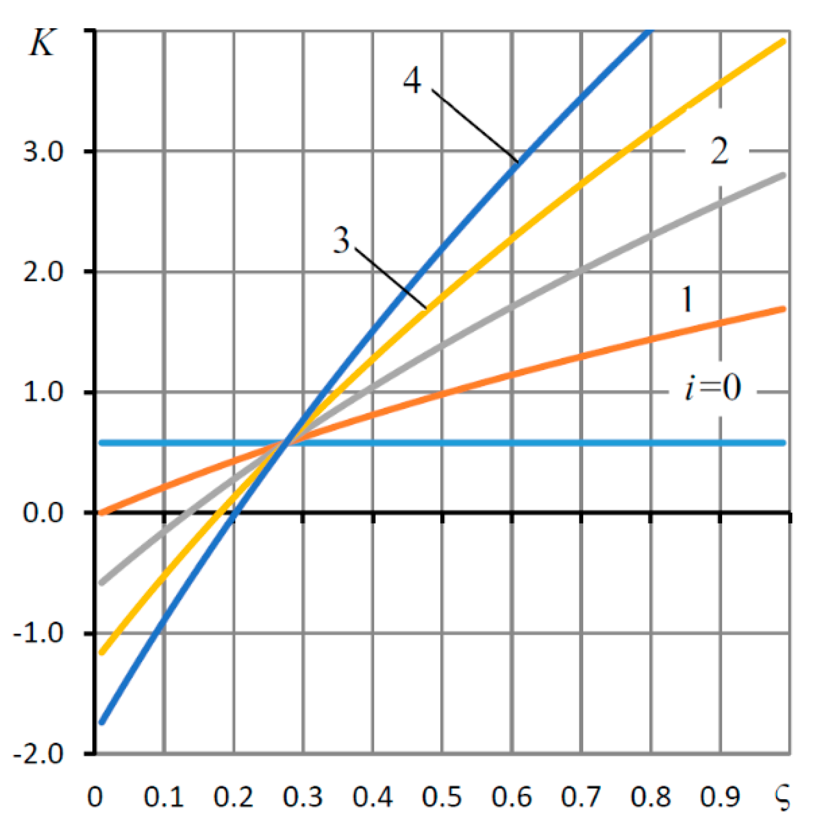
The following parameters are among the input quantities that affect the static compliance of the bearing: L, λ1, λ3, R1, Ps, χ, ς and Ke, where λ1 = L1/L and λ3 = L3/L. Figure 2 and Figure 3 show the dependences of the bearing compliance K on the adjustment coefficients of the resistance of the SECT at various values of the elasticity (compliance) Ke of the elastic suspension for the design point corresponding to the values of the parameters L = 1.5, λ1 = 0.8, λ3 = 0.95, χ = 0.5, R1 = 1.1 and Ps = 4. For the parameter ς, as the study of a number of aerostatic bearings shows, both from the point of view of statics and, especially, dynamics, the best values are 0.1 < ς < 0.25 [12,26,27]. When calculating the static characteristics, ς = 0.15 was taken.

3.5.1. Characteristics of Bearings with Slot Feeders of SECT

The graphs in Figure 2 show the curves of the dependence of the compliance K on the adjustment coefficient χ of the SECT with slotted feeders, where each curve corresponds to different values of Ke = iKe0 for i = 0, 1, 2, 3 and 4. Here, the value of the elastic coefficient Ke0 = 2.54, at which the bearing has zero compliance at the design point, and is calculated by Formula (34).
As can be seen from the figure, the curves are graphs of unimodal functions with a single extremum minimum. The curve for i = 0 corresponds to the compliance of a conventional bearing with SECT and the rigid suspension (6), for which Ke = 0. Such a bearing always has a positive compliance. For this mode, χ = 0.4 is optimal. With the increasing Ke, the compliance of the bearing decreases. Therefore, already at i = 1 (at Ke = Ke0), the bearing at the minimum point of the function K(χ) reaches zero compliance (infinite stiffness). In this case, the value of the optimal χ shifts towards its increase (χ ≈ 0.55). With a further increase in Ke, the bearing compliance becomes negative. Therefore, at Ke = 4Ke0 (i = 4), the optimal value of the negative compliance is approximately four times higher in absolute value than the positive compliance of a conventional bearing (Ke = 0). For this mode, χ = 0.68 is optimal.
The influence of the weight parameter ς of the resistance of the slotted SECT is shown in Figure 3. The value of the parameter is determined by the same formula: Ke = iKe0. With a rigid suspension, ς does not affect the compliance of the bearing. This is due to the fact that the flow principle for both feeders is the same; therefore, the total resistance of the feeders is equivalent to the presence of any of them with the same resistance.
With the increasing Ke, the curves become monotonically increased. In this case, the total eccentricity εs receives an addition to the eccentricity ε component εp, which is formed under the action of the aerostatic reaction force Wp in the inter-throttle chambers upon deformation of the elastic suspension (6), contributing to the change in the nature of the curves. Moreover, the larger the Ke, the steeper the K(ς) curve.
Noteworthy is the presence of a common point ς = ςc on the curves, where the compliance K does not depend on Ke. For those shown in Figure 3, ςc ≈ 0.275. From Formula (33), it follows that this regime takes place at W = Wp, when the aerostatic reactions on the surfaces of the sleeve (3) are equal to each other, and, therefore, the deformation of the elastic suspension is absent for any Ke. Taking this into account, Expressions (26) and (27) make it possible to derive an equation for calculating ςc for the design point mode:
A w k U k = A w p U p .
It follows from the graphs that a decrease in compliance is possible only if 0 ≤ ς < ςc. Moreover, the smaller the ς, the lower the bearing compliance. At the same time, as the study of the dynamics of other types of aerostatic bearings using SECT shows, a decrease in compliance is almost always accompanied by a deterioration in their dynamics up to a loss of stability [12,27]. Therefore, in order to ensure acceptable dynamics, it is recommended to calculate and design low-compliance bearings for the ς ∈ [0.1, 0.2].

3.5.2. Features of Diaphragm Feeder Bearing

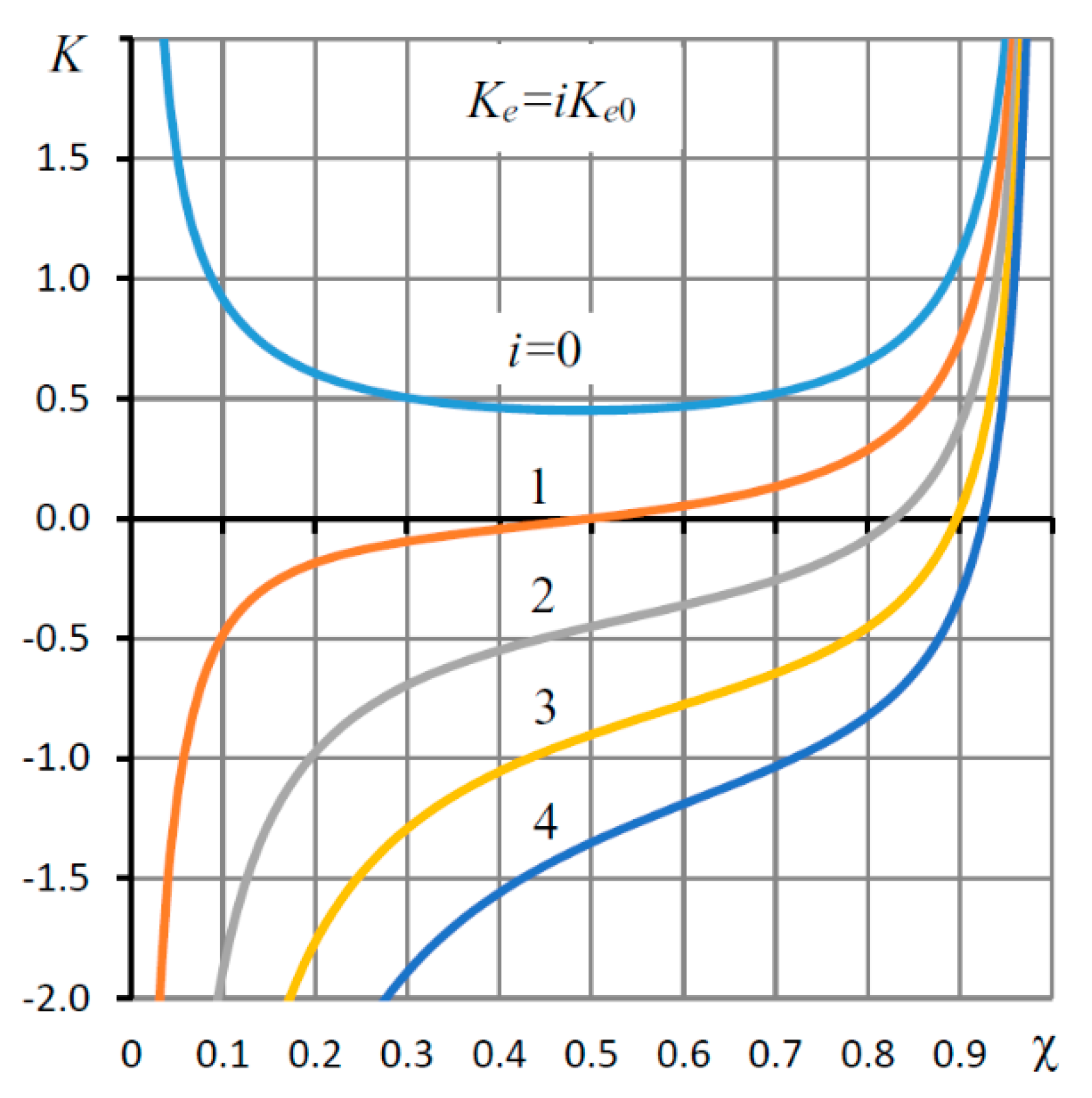
Figure 4 shows similar curves for the compliance function K(χ) versus the χ adjustment coefficient of the SECT with feeders in the form of diaphragms, where the main feeders are simple diaphragms, and the damping feeders are annular diaphragms. In the absence of displacement compensation (Ke = 0) with the rigid suspension (6), the dependence is similar to the analogous characteristic for the slotted SECT. It is also a unimodal function, the minimum of which falls on χ = 0.5. However, for KeKe0, the character of the curves changes, and they become monotonically increased. Therefore, for Ke = Ke0 at the design point χ = 0.5, the bearing has zero compliance (K = 0), which is the boundary between the modes of negative (K < 0) and positive (K > 0) compliance. At Ke > Ke0, the character of the curves remains the same, and the range of negative compliance becomes wider.
An explanation for this phenomenon can be found by analyzing the curves of the graph in Figure 5, which shows the dependences of the coefficients Uk(χ) and Up(χ), included in Formulas (20) and (21), on the coefficient χ. Solid lines correspond to Uk and dotted to Up.
Formulas (26) and (27) show that Uk and Up are, in fact, the amplification factors of the pressure reactions on the inner and outer surfaces of the sleeve (3), respectively. The lines 1 in Figure 5 show that the activity of the bearing capacity W of the slotted SECT determined by the coefficient Uk is higher than the reaction Wp; therefore, the unimodal nature of the dependence of compliance K(χ) is mainly determined by the nature of the inverse reaction function W, which, as can be seen from the graphs at K = 0, is also unimodal.
As can be seen from the graph in Figure 5 for the curves (2), the activity of the throttle SECT reactions for the moderate and large χ is approximately the same, and at the small χ, the activity of the Wp reaction is much higher. Therefore, in contrast to the slotted SECT, for which Uk > Up, for the throttling SECT, UkUp; hence, for the latter, the reaction activity Wp is higher, which explains the monotonic character of the K(χ) dependences.
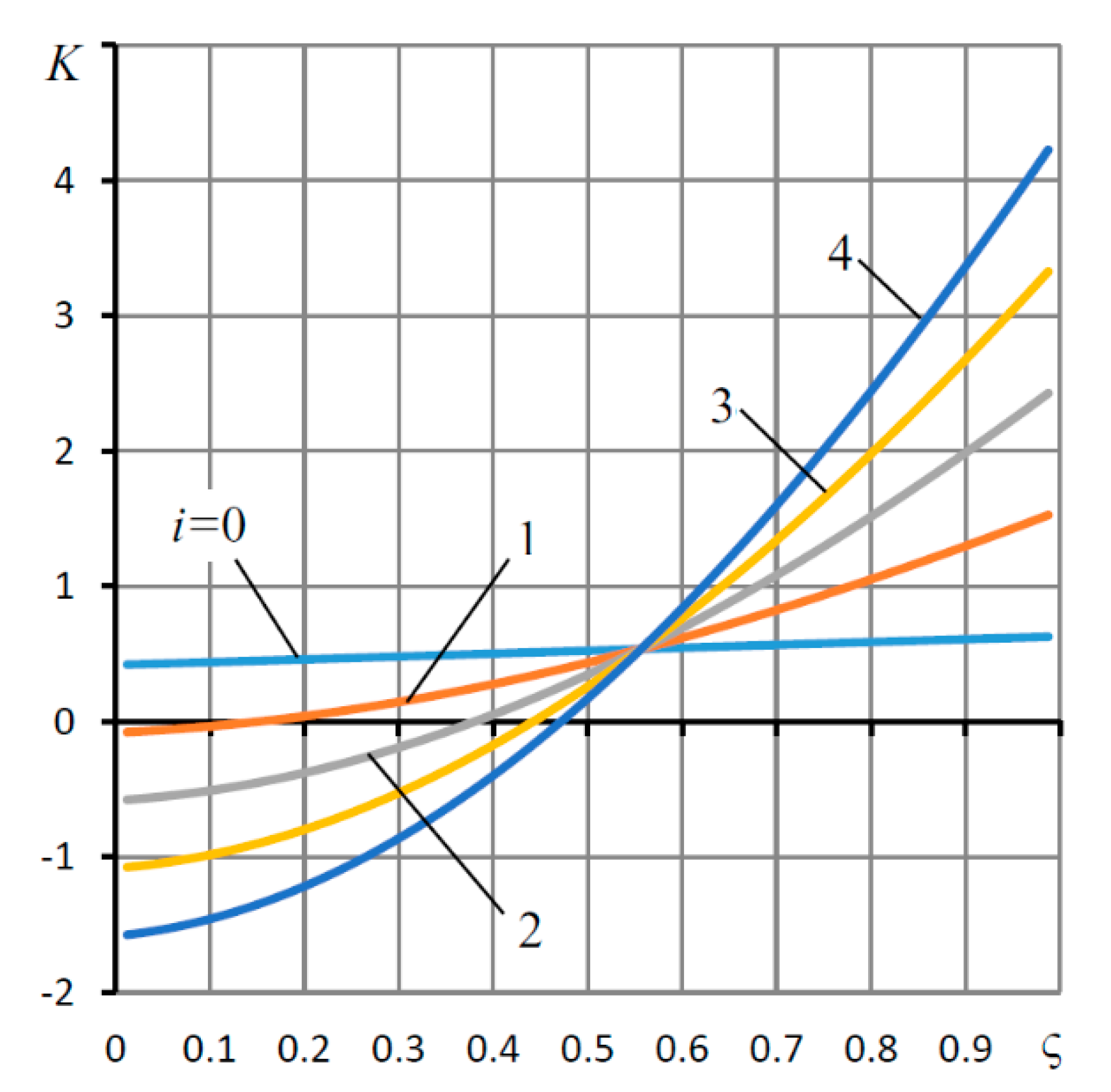
Similar to Figure 3, the dependences for the weight parameter ς of the resistances of the throttle SECT are shown in Figure 6.
At Ke = 0, which corresponds to the rigid suspension (6), in contrast to the slotted SECT, where ς does not affect the bearing compliance, for the throttle SECT, the function K(ς) is monotonically increased. This is explained by the fact that, at ς = 0, single throttling occurs with simple diaphragms, and at ς = 1, single throttling is carried out by annular diaphragms. Since the flexibility of supports with simple diaphragms is higher, then K(0) < K(ς) < K(1), which explains the monotonic nature of the function K(ς) at Ke = 0 (i = 0).
It is noteworthy that the common point of the curves of the bearing with the throttle SECT, as compared to the slotted system, is shifted to the right by a much greater distance: in this case, ςc ≈ 0.554.
In a bearing with a throttle SECT for Ke > 0, the dependences K(ς) have similar characters. However, there is one fundamental difference—if, for a bearing with a slotted SECT, the dependences K(ς) are convex ( 2 K ς 2 < 0 ) ; however, for a throttle SECT, they, on the contrary, are concave ( 2 K ς 2 > 0 ) .
Obviously, the fundamentally different nature of the curvature of these dependences is based on the same explanation—the difference in the activity of the force reactions W and Wp of the considered SECT systems.
Summing up the study of the static characteristics calculated by the small parameter method, we can conclude that, in comparison with slot feeders, the throttling SECT gives better characteristics of low compliance due to the greater activity of the force reaction of the compressed air in the inter-throttling chambers.
Since, in real conditions, the bearing usually operates with a significant radial displacement, it is of interest to characterize the compliance with arbitrary values of the eccentricity ε. This research is carried out in the next section of the paper.

4. Nonlinear Mathematical Model of the Bearing Stationary State

In this section, a stationary mathematical model of a bearing with a slotted and throttled SECT is considered for the arbitrary values of the eccentricity ε. The solution of the boundary value problems for the Reynolds differential equation is obtained by the finite-difference method.

4.1. Bearing Model with Slotted SECT

Consider the mathematical model (1)–(5) and divide a segment φ [ 0 , π ] into even number m parts and a segment Z [ 0 , L ] into even number n parts. We transform the Reynolds Equation (1) and write it in the form
U Ψ φ + 2 Ψ φ 2 + 2 Ψ Z 2 = 0 ,
where Ψ ( Z , φ ) = P 2 ( Z , φ ) , U ( φ ) = 3 H H = 3 sin φ 1 ε cos φ .
Let us write Equation (36) in a finite-difference form [28,29]:
U j Ψ i j + 1 Ψ i j 1 2 ν φ + Ψ i j + 1 2 Ψ i j + Ψ i j 1 ν φ 2 + Ψ i + 1 j 2 Ψ i j + Ψ i 1 j ν z 2 = 0 ,
where ν φ = π m , ν z = L n are the steps of integration over the variables φ and Z, and j = 1, 2,…, m − 1; i = 1, 2,…, k − 1, k + 1,…, n − 1 are the numbers of the nodal points for these variables (for the injection line i = k, a separate equation is shown below).
We write the first boundary condition (3) in the form [29]
Ψ 2 j + 4 Ψ 1 j 3 Ψ 0 j 2 ν z = 0 .
The second boundary condition (3) for j = 0, 2, ..., m is
Ψ k j = ( P k 2 ) j ,
where k = [ n L 1 L ] is the number of the point on the grid of the longitudinal axis, which corresponds to the location of the feed slot Z = L1.
The last condition (4) for j = 0, 1, ..., m is
Ψ n j = 1 .
The boundary conditions (5) for i = 0, 1, ..., n can be written as
Ψ i 1 = Ψ i 1 , Ψ i m + 1 = Ψ i m 1 .
We represent (37) in the form
( b 0 + a 0 U j ) Ψ i j + 1 + c 0 Ψ i j ( b 0 a 0 U j ) Ψ i j 1 + Ψ i + 1 j + Ψ i 1 j = 0 ,
where a 0 = ν z 2 2 ν φ , b 0 = ( ν z ν φ ) 2 , c 0 = ( 1 + b 0 ) .
We write (41) in vector form
Ψ ¯ i + 1 + A 1 Ψ ¯ i + Ψ ¯ i 1 = 0 ,
where
Ψ ¯ i = [ Ψ i 0 Ψ i 1 Ψ i m 1 Ψ i m ]
is a vector of the length m + 1, and
A 1 = [ c 0 2 b 0 0 0 0 0 ( b 0 a 0 U 1 ) c 0 ( b 0 + a 0 U 1 ) 0 0 0 0 0 0 ( b 0 a 0 U m 1 ) c 0 ( b 0 + a 0 U m 1 ) 0 0 0 0 2 b 0 c 0 ]
is a square tridiagonal matrix of size ( m + 1 ) × ( m + 1 ) .
Condition (38) can be written in vector form
Ψ ¯ 2 + 4 Ψ ¯ 1 3 Ψ ¯ 0 = 0 .
Let us write a vector equation similar to (37) corresponding to the line i = k of the air supply to the carrier gap. To do this, we use the equations for the balance of flow rates (9), (12) and (13).
Applying the well-known formulas of the quadratic order of accuracy to represent the first derivative of a function at the edges of the segment [29], we write the formulas for the flow rate in the carrier gap on the pressurization line
Q h , j = Q h 1 , j Q h 2 , j = = H j 3 2 ν z ( Ψ k + 2 j 4 Ψ k + 1 j + 6 Ψ k j 4 Ψ k 1 j + Ψ k 2 j ) .
For the flow rate Formulas (9), we obtain
{ Q k , j = A k ( P p , j 2 P k , j 2 ) , Q p , j = A p ( P s 2 P p , j 2 ) .
Using the third equation of System (7) and excluding P p , j 2 , we get
Q k , j = A k p ( P s 2 P k , j 2 ) ,
where A k p = A k A p A k + A k .
Using the last equation of system (7) and taking into account that P k , j 2 = Ψ k j , we write an analog of the last Equation (7) in the finite-difference form
Ψ k + 2 j 4 Ψ k + 1 j + b j Ψ k j 4 Ψ k 1 j + Ψ k 2 j = c j ,
where b j = 6 + a j , c j = a j P s 2 , a j = 2 ν z A k p H j 3 .
The vector form (49) is the equation
Ψ ¯ k + 2 4 Ψ ¯ k + 1 + A 2 Ψ ¯ k 4 Ψ ¯ k 1 + Ψ ¯ k + 1 = C ¯ 1 ,
where
C ¯ 1 = [ c 0 c 1 c m 1 c m ] ,     A 2 = [ b 0 0 0 0 0 0 0 b 1 0 0 0 0 b j 0 0 0 0 b m 1 0 0 0 0 0 0 b m ] .
Let us write Equations (42) for i = k − 1 and i = k + 1 in the form
{ Ψ ¯ k + 2 = A 1 Ψ ¯ k + 1 Ψ ¯ k , Ψ ¯ k 2 = A 1 Ψ ¯ k 1 Ψ ¯ k .
Substituting (51) into (50), we obtain the vector equation
( 4 E + A 1 ) Ψ ¯ k + 1 + A 2 Ψ ¯ k ( 4 E + A 1 ) Ψ ¯ k 1 = C 1 ¯ .
Let us reduce (52) to the form (42)
Ψ ¯ k + 1 + A 3 Ψ ¯ k + Ψ ¯ k 1 = C 2 ¯ ,
where A 3 = ( 4 E + A 1 ) 1 A 2 , C 2 ¯ = ( 4 E + A 1 ) 1 C 1 ¯ , E is the identity matrix.
We write the vector Equations (42) and (53) in the general form
Ψ ¯ i + 1 + A 4 Ψ ¯ i + Ψ ¯ i 1 = C 3 ¯ ,
where
A 4 = { A 1 , i = 1 , 2 , , k 1 , k + 1 , , n 1 A 3 , i = k , C 3 ¯ = { 0 , i = 1 , 2 , , k 1 , k + 1 , , n 1 C 2 ¯ , i = k
The solution of the finite-difference problems (37)–(40) is found by the matrix sweep method [30]. For this, we will use the recurrence formula
Ψ ¯ i 1 = X i Ψ ¯ i + y ¯ i ,
where X i , y ¯ i are matrices of size ( m + 1 ) × ( m + 1 ) and vectors of size m + 1, i = 1, 2,…, n.
Substituting (55) into (54), we obtain
Ψ ¯ i + 1 + ( A 4 + X i ) Ψ ¯ i + y ¯ i = C ¯ 3 .
Let us reduce (56) to form (55):
Ψ ¯ i = ( A 4 + X i ) 1 Ψ ¯ i + 1 ( A 1 + X i ) 1 ( y ¯ i C ¯ 3 ) .
Comparing (57) with (55), we find recurrent formulas for calculating the sweep matrices and vectors
X i + 1 = ( A 4 + X i ) 1 , y ¯ i + 1 = X i + 1 ( y ¯ i C ¯ 3 ) , i = 1 , 2 , , n 1 .
We find the initial matrix and vector X 1 , y ¯ 1 . To do this, write (42) for i = 1
Ψ ¯ 2 + A 1 Ψ ¯ 1 + Ψ ¯ 0 = 0 .
Adding Equations (45) and (59), we obtain the equation
( A 1 + 4 E ) Ψ ¯ 1 2 Ψ ¯ 0 = 0 .
Let us reduce (60) to the form (55):
Ψ ¯ 0 = ( 1 2 A 1 + 2 E ) Ψ ¯ 1 .
Comparing (61) with (55), we find the initial sweep matrix and vector:
X 1 = 1 2 A 1 + 2 E , y ¯ 1 = 0 .
Using (62), sweep matrices and vectors were found by a forward sweep with the formulas (55) for i = 1, 2, …, n − 1. The reverse sweep was performed using the vector (39) and formulas (55) for i = n, n − 1, …, 1. As a result, the field of the pressure square P2 in the carrier gap and the vector of the pressure square Pp2 in the throttle chambers were obtained.
The bearing capacity
W = 2 π 0 π 0 L ( P 1 ) cos φ d Z d φ
was determined by the Simpson cubature formula [31], and the reaction of the pressure forces (27) in the throttle chambers was found by the Simpson quadrature formula [32]
W p = 2 L 3 R 1 π 0 π ( P p 1 ) cos φ d φ .
The bearing compliance was calculated by differentiating a directional spline [33] made from the points of the load curve.

4.2. Analysis of the Static Characteristics of a Bearing with a Slotted SECT

The static characteristics calculated according to the formulas in Section 3.1 correspond to the values of the parameters used for plotting the graphs in Section 3.5.2. The characteristics were calculated point-by-point for different values of the eccentricity ε (0, 1) with a small step εh = 0.05. The dependences εs(F) were determined by calculating the parametric functions εs(ε) and W(ε), since F = W. The calculations showed that, sufficient for practice accuracy, | W n W 2 n | < 0.001 , | W m W 2 m | < 0.001 is achieved when dividing the above integration intervals into n = 40 and m = 16 parts.
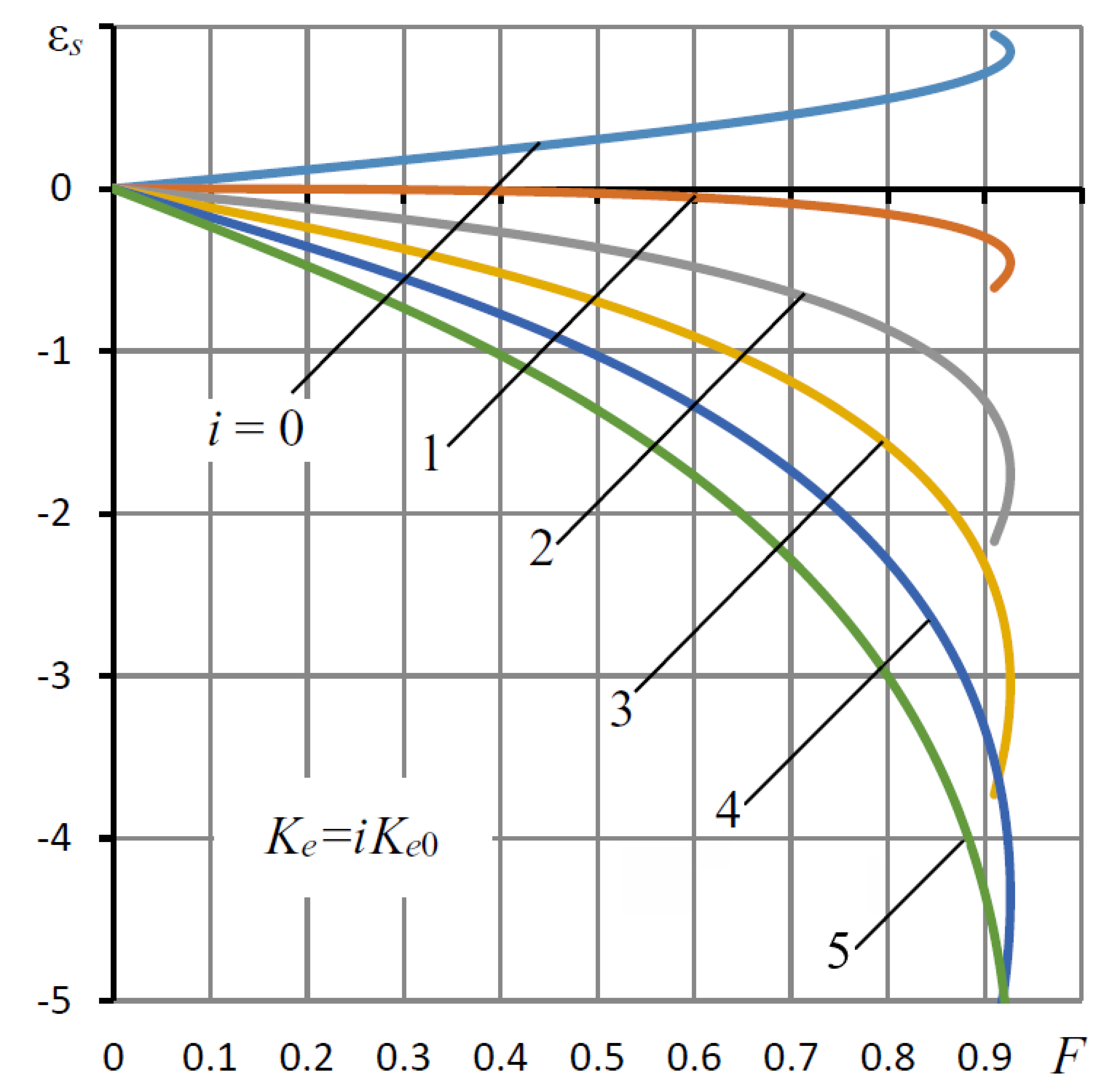
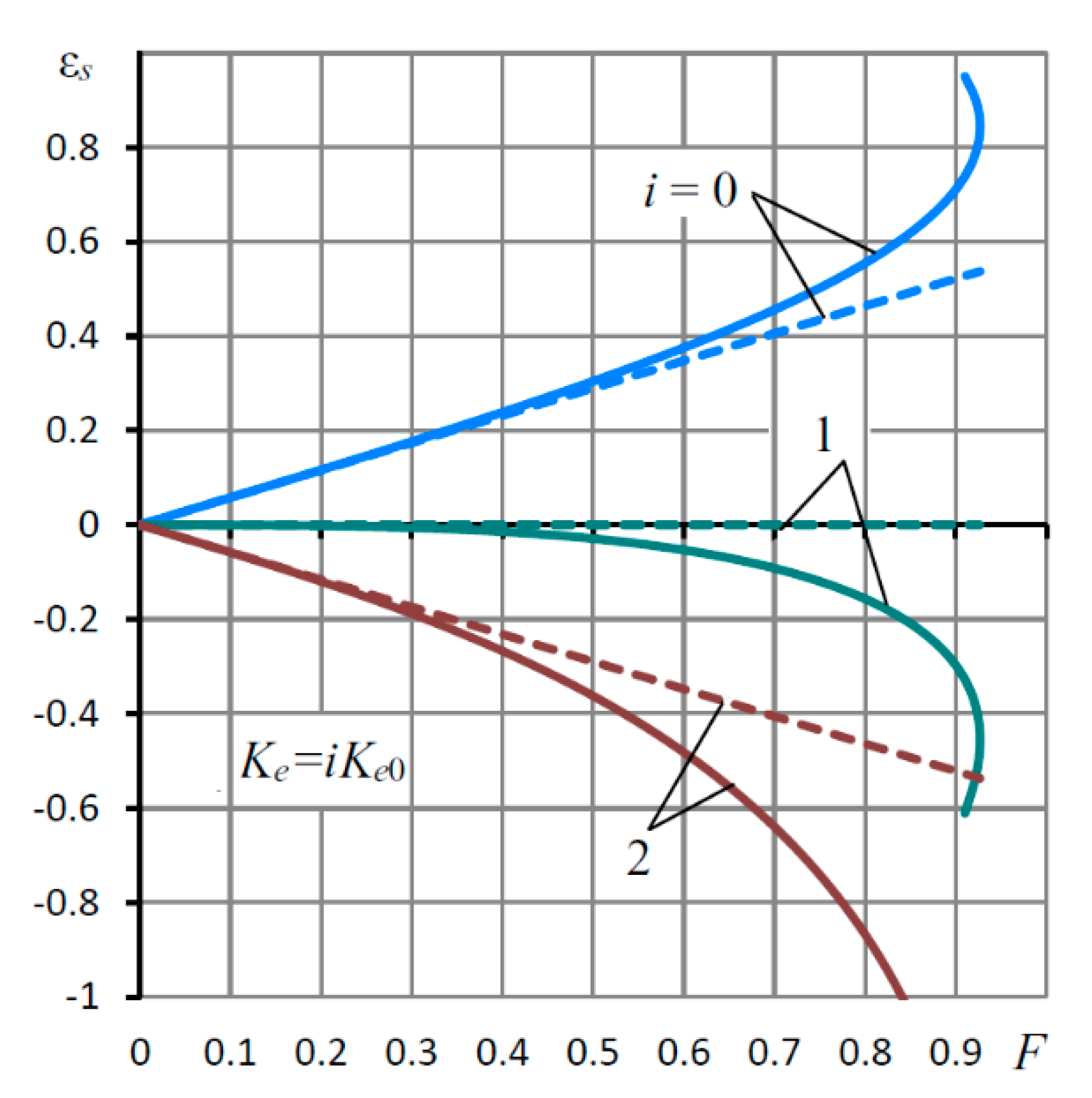
In Figure 7, the load curves εs(F) for different values of the coefficient of elasticity Ke are shown. The curve for i = 0 (Ke = 0) corresponds to a conventional bearing of positive compliance with a slotted SECT and rigid suspension (4) of the sleeve (3). It can be seen from the graphs that the positive compliance of the bearing remains in a fairly wide range of loads and eccentricity. However, in the area of extreme values of eccentricity at ε > 0.85, the bearing loses its rigidity and even acquires negative compliance. This area of theoretical performance is unrealizable in practice, since it corresponds to a statically unstable bearing.
At i = 1 (Ke = Ke0), the bearing at ε = 0 has zero compliance (K = 0). With an increase in load F, the curve deviates into the region of negative eccentricities, while the nature of the curve changes; now, the eccentricity does not increase but, on the contrary, decreases. The same applies to the regimes of negative compliance i > 1 (Ke > Ke0) at the initial point of the curves. As in a bearing with a rigid suspension in the area of loads at which a conventional bearing loses its static stability, this bearing also loses stability at zero and negative compliance. The difference is only in the sign of the curvature of the characteristics.
Figure 8 shows the characteristics of nonlinear and linear models.
The first (solid curves) are calculated by the formulas of Section 4.1, and the second (dashed lines) are calculated by the formula
e s = K 0 F ,
where K0 is the bearing compliance calculated by Formula (33).
In the region of low loads, the graphs show complete coincidence of the characteristics, which confirms the correctness of the formulas derived in Section 4.1 for calculating nonlinear dependencies.
At Ke = 0, the compliance is stable up to F = 0.4. With the increasing Ke, the stability of the characteristics deteriorates. Thus, at Ke = 2Ke0, with negative compliance, a noticeable divergence of lines is observed even at a load of F = 0.2. At F > 0.7, the discrepancy becomes significant.
The stability of compliance is important in the sense that the deformations of the technological system of the machine, as a rule, are linear functions of the load; therefore, those bearings of negative compliance are the most effective, the load characteristics of which are close to linear ones. As can be seen from the graph in Figure 8, bearings with slotted SECT meet this criterion only in the areas of low and moderate loads. Earlier, it was shown that bearings with throttle SECT have better characteristics. It should be expected that they will be the best under arbitrary loads and eccentricities.

4.3. Bearing Model with Throttle SECT

This model is based on a slotted bearing model. The only difference is that, instead of dependences (9) that are linear with respect to the square of the pressure, nonlinear dependences (10) are used. This difference is reflected in the entire system of equations, which also will be nonlinear for this model. From the total number of n (m + 1) equations with respect to the value of the squared pressure at the nodes of the finite-difference mesh, 2 (m + 1) equations will be nonlinear (these equations correspond to the injection line i = k), and the rest of the equations remain linear.
Using the fact that, for ik, the system (37) is linear, we apply the counter-sweep method, which will allow excluding (n − 2) (m + 1) linear equations from this system. In this case, only nonlinear equations will remain, to the solution of which, the Seidel iterative method will be applied.
To eliminate linear equations, we use the opposite methods of left and right sweep. For the left sweep, we will use the recurrent Formula (55) for i = 1, 2,…, k. For the right sweep, we use the recurrent formula
Ψ ¯ i + 1 = V i Ψ ¯ i + z ¯ i ,
where V i , z ¯ i are matrices of size ( m + 1 ) × ( m + 1 ) and vectors of size m + 1, i = n − 1, 2, …, k.
If the left straight sweep starts from the left edge of the segment Z [0, L], then the right straight sweep will start from the right edge of this segment, for which the initial value of the unknown function is determined by Formula (39). Writing (66) for i = n − 1, and comparing the formula with (39), we find the initial sweep coefficients of the right straight sweep
V n 1 = 0 , z ¯ n 1 = 1 ¯ .
Performing straight left and right sweeps with Formulas (55) and (67), we find sweep matrices and vectors X i , y ¯ i for i = 1, 2, …, k and for i = n − 1, 2, …, k.
For the flow rate of the bearing gap, we will use Formula (46). Similar to (47), the formulas (10) for the flow rates through the throttles take the form
{ Q k , j = A k H j Π ( P p , j , P k , j ) , Q p , j = A p Π ( P s , P p , j ) .
Substituting (46) and (68) into the balance equations for the flow rate (7), we obtain a nonlinear system of finite-difference equations
{ H j 3 2 ν z ( Ψ k + 2 j 4 Ψ k + 1 j + 6 Ψ k j 4 Ψ k 1 j + Ψ k 2 j ) = = A k H j Π ( P p , j , P k , j ) , A k H j Π ( P p , j , P k , j ) = A p Π ( P s , P p , j ) .
After performing the transformations, we write System (69) in a matrix form
{ Ψ ¯ k + 2 4 Ψ ¯ k + 1 + 6 Ψ ¯ k 4 Ψ ¯ k 1 + Ψ ¯ k 2 = d ¯ k , d ¯ k = d ¯ p ,
where d k , j = 2 ν z A k H j 2 Π ( P p , j , P k , j ) , d p , j = 2 ν z A p H j 3 Π ( P s , P p , j ) .
For i = k − 1 for the left sweep formula and i = k + 1 for the right sweep formula, we have a sweep system of matrix equations:
{ Ψ ¯ k 2 = X k 1 Ψ ¯ k 1 + y ¯ k 1 , Ψ ¯ k + 2 = V k + 1 Ψ ¯ k + 1 + z ¯ k + 1 .
Substituting (71) into the first equation of (70), we obtain
A 5 Ψ ¯ k + 1 + 6 Ψ ¯ k + A 6 Ψ ¯ k 1 = d ¯ k C ¯ 4 ,
where A 5 = ( V k + 1 4 E ) , A 6 = ( X k 1 4 E ) , C ¯ 4 = y ¯ k 1 + z ¯ k + 1 .
For i = k for the left and right sweep formulas, we have a system of matrix equations similar to (71):
{ Ψ ¯ k 1 = X k Ψ ¯ k + y ¯ k , Ψ ¯ k + 1 = V k Ψ ¯ k + z ¯ k .
Substituting (73) into (72), we transform System (70) into the form
{ Ψ ¯ k = A 8 d ¯ k C ¯ 6 , d ¯ k = d ¯ p ,
where
A 8 = A 7 1 , C ¯ 6 = A 8 C ¯ 5 , A 7 = A 5 V k + A 6 X k + 6 E , C ¯ 5 = C ¯ 4 + A 5 z ¯ k + 1 + A 6 y ¯ k 1 .
The nonlinear system (74) was solved by the Seidel iterative method [34]. The initial values of the pressure vectors P ¯ k , P ¯ p were taken to be the pressure values calculated by Formulas (17) in the absence of a bearing load. These values were substituted into the right-hand side of the first equation of (74), then Ψ ¯ k . were calculated. Since Ψ k j = ( P k 2 ) j , the new value of the pressure Pk at the grid nodes was found by the formula P k j = Ψ k j . New values of the pressure Pp were found by solving the second equation of System (74), which is also nonlinear. Taking into account the fact that P p j [ P k j , P s ] , the solution of this equation for each value j = 0, 1, ..., m was found by the bisection method. Further, the new pressure values were again substituted into the right side of the first equation of (74), and the process was continued until its convergence. The process was stopped after the conditions were met:
| ( P k j ) α + 1 ( P k j ) α | < δ , j = 0 , 1 , , m ,
where α is the iteration number, and δ is the calculation accuracy (in the calculations, δ = 10−4 was taken).
After finding Ψ ¯ k by Formulas (55) and (66), the reverse left and right sweeps were performed, as a result of which, the field of pressure squares P2 in the bearing gap were obtained, and then, the force reactions W and Wp were found.

4.4. Analysis of the Static Characteristics of a Bearing with a Throttle SECT

The calculations showed that the iterative process converges rapidly at small values of the eccentricity ε. At medium ε, the process slowed down, assumed an oscillatory character and diverged even at ε = 0.4. To improve the convergence, taking into account the oscillation of the process at each step, a new approximation for the vector was calculated by the formula
( P k j ) α = ( P k j ) α 1 + γ [ ( P k j ) α 1 + ( P k j ) α 2 ] , j = 0 , 1 , , m ,
where α is the iteration number, and γ is the coefficient.
In addition, for medium and large ε, a recursion was used, the meaning of which was that the pressure vector obtained after the end of the iterative process for the previous smaller ε was taken as the initial approximation for the new ε. Thus, to obtain a solution to the problem at ε = 0.7, the problems for ε = 0.1, 0.2, …, 0.6 were successively solved. In this case, for the limiting ε, it was necessary to decrease γ to 0.1. The maximum number of iterations recorded for the slowest process was α = 980. The average number of iterations was α = 20.
An increase in the rate of convergence of the iterative process was also facilitated by the fact that matrices X, V and A and vectors y ¯ , z ¯ , C ¯ do not depend on pressures P ¯ k , P ¯ p , ; therefore, for a single ε, they would be calculated once. In this case, the speed of the iterative process would be determined by the rate of multiplication of the matrix A7 by the vector d ¯ k and by the rate of solving m + 1 nonlinear equations when determining the vector P ¯ p by the bisection method. When solving the problem for a single ε on a regular PC, this required no more than 0.1 s of computation time.
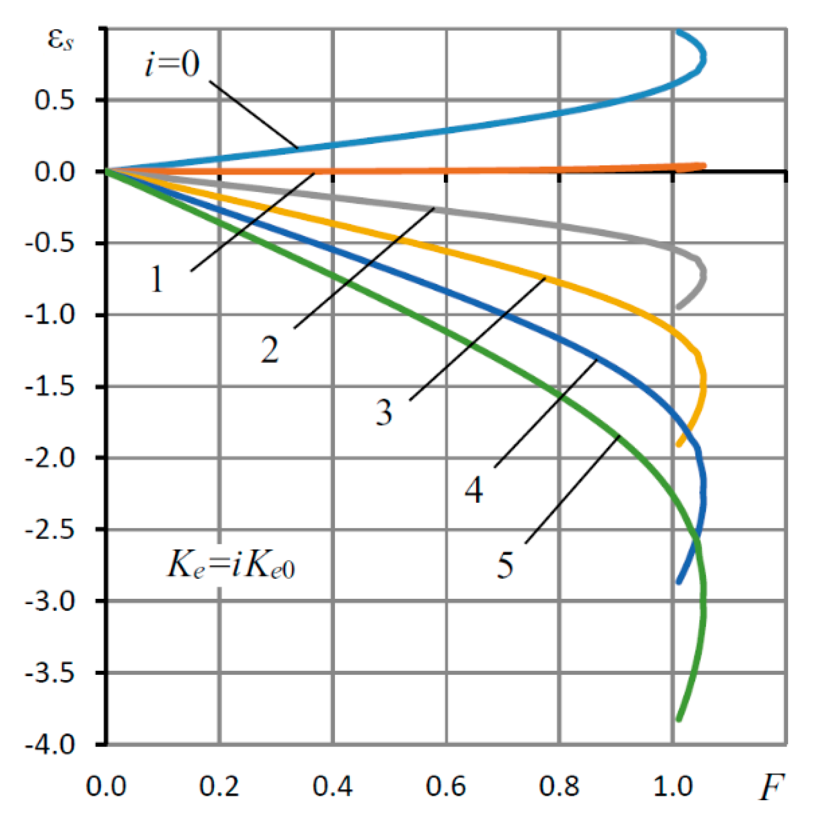
Figure 9 shows the load curves εs (F) of a bearing with a throttle SECT for different values of the elastic coefficient Ke.
The curve for i = 0 (Ke = 0) corresponds to a conventional bearing of positive compliance with a rigid suspension (4) of the sleeve (3). It can be seen from the graphs that, as in the case of the slotted SECT, the positive compliance of the bearing also remains in a rather wide range of loads and eccentricity. Similarly, in the range of eccentricity limit values at ε > 0.85, the bearing loses its rigidity and becomes statically unstable.
The graphs show that the maximum bearing capacity of a throttle-type bearing is greater than one of a slotted bearing. Therefore, if for the latter, the maximum bearing capacity is Wmax = 0.93, and then, for the first one, Wmax = 1.06, that is 14% more. It is also seen that the first bearing has a more stable load characteristic. In this respect, the graphs in Figure 10 are meaningful, where the curves calculated according to the nonlinear theory and the straight lines obtained by Formula (65) for the K0 of the bearing with the throttle SECT are shown. The best stability of the characteristics is observed for all K0. Moreover, if the first has a stable load characteristic for F ≤ 0.2, then the second has this characteristic four times wider: F ≤ 0.8.
The results obtained indicate that, even at arbitrary loads and eccentricities, a bearing with a throttling SECT is significantly better than a bearing with a slotted SECT.

5. Mathematical Model of the Unsteady State of the Bearing

It is known that, with a decrease in compliance, the dynamic characteristics of aerostatic bearings deteriorate [13]. Low dynamics are inherent in lightly loaded structures. As the load increases, the bearing dynamics usually improve. Thus, loading is a factor in improving the dynamic quality of the bearings.
In this section, nonstationary mathematical models of bearings with slotted and throttling SECT are considered for small values of eccentricity ε. The solution of the boundary value problems for the nonstationary differential Reynolds equation is obtained by the finite-difference method.

5.1. Method for Determining the Transfer Function of a Dynamic System

The pressure function P(Z,φ,τ) in the carrier gap satisfies the dimensionless nonstationary Reynolds equation [25]
φ ( H 3 P P φ ) + Z ( H 3 P P Z ) = σ ( P H ) τ ,
where Z and φ are dimensionless longitudinal and circumferential coordinates, τ is the dimensionless time, σ = 12 μ r 0 2 h 0 2 p a t 0 is the so-called squeezing number [27] and σ = 12 μ r 0 2 h 0 2 p a t 0 is the scale of the current time.
At low loads ΔF(τ), the changes in the gap and pressures on the injection line will be small:
H ( φ , τ ) = 1 Δ H = 1 Δ ε ( τ ) cos φ ,
P k ( φ , τ ) = P k 0 + Δ P k ( τ ) cos φ ,
P p ( φ , τ ) = P p 0 + Δ P p ( τ ) cos φ .
By an analogy with (77) and (78), we represent the pressure distributed in the lubricant gap in the form
P ( Z , φ , τ ) = P 0 ( Z ) + Δ P ( Z , τ ) cos φ .
Substituting (76) and (79) into (75), performing linearization and the subsequent Laplace transform [35], we obtain the problem
{ d 2 Δ Ψ ¯ d Z 2 Δ Ψ ¯ = σ s ( Δ Ψ ¯ P 0 P 0 Δ ε ¯ ) , d Δ Ψ ¯ d Z ( 0 , s ) = 0 , Δ Ψ ¯ ( L 1 , s ) = Δ Ψ ¯ k , Δ Ψ ¯ ( L , s ) = 0 , Δ Ψ ¯ = P 0 Δ P ¯ , Δ Ψ ¯ k = P k 0 Δ P ¯ k ,
where s is the Laplace transform variable, and Δ ε ¯ ( s ) , Δ P ¯ k ( s ) , Δ P ¯ ( s ) are the Laplace transformants of the deviations of pressures P and Pk and eccentricity ε from their equilibrium state.
Problem (80) has no analytical solution; therefore, we apply the superposition method to it and represent the required function as a linear combination:
Δ Ψ ¯ = U k ( Z , s ) Δ Ψ ¯ k + U ε ( Z , s ) Δ ε ¯ .
Substituting (81) into (80) and separating the transformants, we obtain two boundary value problems for the functions U, which can be represented in the following general form:
{ U G 1 U + G 2 = 0 , U ( 0 ) = 0 , U ( L 1 ) = ( 1 α ) , U ( L ) = 0 ,
where α = 0 corresponds to Uk, α = 1 − Uε, G 1 ( Z ) = 1 + σ s P 0 ( Z ) , G 2 ( Z ) = α σ s P 0 ( Z ) , and P 0 ( Z ) is the stationary pressure distribution function (14).
The solution to Problem (82) was obtained by the finite-difference sweep method [29]. To do this, we divided the integration segment [0, L] into an even quantity n of equal parts and replaced the differential equations with their algebraic analogs:
U i + 1 2 U i + U i 1 ν 2 G 1 , i U i + G 2 , i = 0 ,
where ν = L/n is the grid step, i = 1, 2,…, n − 1 is the number of its node and G 1 , i = 1 + σ s P 0 , i , G 2 , i = α σ s P 0 , i , P 0 , i = P 0 ( Z i ) , Z i = i ν .
After the transformations, (83) was represented in the form
U i + 1 G 3 , i U i + U i 1 + G 4 , i = 0 ,
where G 3 , i = 2 + ν 2 ( 1 + σ s P 0 , i ) , G 4 , i = α σ ν 2 P 0 , i s .
The boundary conditions for (84) have the form
U 2 + 4 U 1 3 U 0 2 ν , U k = 1 α , U n = 0 ,
where k = [ n L 1 L ] is the node number corresponding to the pressurization line Z = L1.
The solution was obtained in the form
U i 1 = X i U i + Y i ,
where Xj and Yj are the sweep coefficients.
A double run was performed: the first for i = 1, 2, ..., k − 1 and the second for i = k + 1, k + 2, ..., n − 1.
The initial coefficients for the first run were found by solving the system of equations derived from the first boundary condition (85) and Equation (84) for i = 1
{ U 2 + 4 U 1 + 3 U 0 = 0 , U 2 G 3 , 1 U 1 + U 0 + G 4 , 1 = 0 .
Eliminating U2, we found
U 0 = 4 G 3 , 1 2 U 1 + G 4 , 1 2 .
Comparing (88) with (86) for i = 1, we found the initial sweep coefficients for the first sweep:
X 1 = 4 G 3 , 1 2 , Y 1 = G 4 , 1 2 .
Using the boundary conditions (85), we obtained the initial sweep coefficients for the second sweep:
X k + 1 = 0 , Y k + 1 = 1 α .
The final values of the function for the first and second runs are the last two boundary conditions (85).
Substituting (86) into (84), we found recurrent formulas for the sweep coefficients
X i + 1 = 1 G 3 , i X i , Y j + 1 = X i + 1 ( Y i + G 4 , i ) .
Performing sweeps for α = 0 and α = 1 using the Simpson numerical quadrature the formula, we determined the coefficients
U w = ν P k 0 3 i = 0 n λ i U i
of the bearing capacity transformants
Δ W ¯ = U w , k Δ P ¯ k U w , e Δ ε ¯ ,
where λ i are the coefficients of the Simpson quadrature formula [32].
The transformant of the flow rate in the carrier gap on the pressurization line is determined by the formula
Δ Q ¯ h = Δ Q ¯ h + Δ Q ¯ h = U q k Δ P ¯ k U q e Δ ε ¯ ,
where Δ Q ¯ h + , Δ Q ¯ h are the components of the discharge in the direction of the end and center of the bearing gap, respectively,
Δ Q ¯ h ± = ( 2 d Δ Ψ ¯ d Z + 3 d P 0 2 d Z Δ ε ¯ ) Z = L 1
The flow rates at Δ P ¯ k , Δ ε ¯ were calculated using the numerical formulas of the first derivative for the quadratic order of accuracy [29]:
U q = P k 0 ν ( U k 2 4 U k 1 + 6 U k 4 U k + 1 + U k + 2 ) .

5.2. Derivation of the Formula for the Dynamic Compliance of the Bearing

The system of dynamic equations for the transformants has the form
{ Δ W ¯ + Δ F ¯ i n = Δ F ¯ , Δ Q ¯ p Δ Q ¯ k Δ Q ¯ v = 0 , Δ Q ¯ k Δ Q ¯ h = 0 , Δ ε ¯ p K e ( Δ W ¯ Δ W ¯ p ) = 0 , Δ ε ¯ s Δ ε ¯ p Δ ε ¯ ,
where Δ ε ¯ s , Δ ε ¯ p , Δ ε ¯ are the transformants of the corresponding eccentricities, the transformed shaft mass inertia
Δ F ¯ i n = M a s s 2 Δ ε ¯ ,
The transformed reaction of pressure forces in the throttle chambers
Δ W ¯ p = U p Δ P ¯ p ,
The transformant of the flow rate associated with the air compressibility in the throttle chambers
Δ Q ¯ v = A v s Δ P ¯ p ,
And the transformed flow rates
Δ Q k ¯ = A 2 Δ P ¯ k + A 3 Δ P ¯ p A 4 Δ ε ¯ ,
Δ Q p ¯ = A 5 Δ P p ¯ ,
where A v = σ V p , Vp is the volume of the inter-throttling chambers that is reduced to the volume of the carrier gap, U p = L 3 R 1 ,   M a s = m s h 0 2 π t 0 2 r 0 2 p a is dimensionless shaft mass, ms is the shaft mass and A2A5 are coefficients of Formulas (30) for the flow functions of the slotted or throttle SECT.
To obtain the formula for the dynamic compliance of the bearing, we exclude the transformants Δ P ¯ k , Δ P ¯ p from System (92). For this, we write the second and third equations in matrix form:
[ ( A q k A 2 ) A 3 A 2 A 3 A 5 + A v s ] [ Δ P ¯ k Δ P ¯ p ] = [ A q e A 4 A 4 ] Δ ε ¯ .
Having solved (98), we express Δ P ¯ k , Δ P ¯ p in terms of Δ ε ¯
{ Δ P ¯ k = A 6 Δ ε ¯ , Δ P ¯ p = A 7 Δ ε ¯ ,
where
A 6 = ( A q e A 4 ) ( A 3 A 5 + A v s ) + A 3 A 4 ( A q k A 2 ) ( A 3 A 5 + A v s ) + A 2 A 3 , A 7 = ( A q k A 2 ) A 4 A 2 ( A q e A 4 ) ( A q k A 2 ) ( A 3 A 5 + A v s ) + A 2 A 3 .
Substituting (99) into (90), (94) and the last two equations of (92), we obtain
{ Δ W ¯ + Δ F ¯ i n = Δ F ¯ = A 8 Δ ε ¯ , Δ W ¯ p = A 9 Δ ε ¯ , Δ ε ¯ s = A 10 Δ ε ¯ ,
where A 8 = A w k A 6 A w e + M a s s 2 , A 9 = U p A 7 ,   and A 10 = 1 + K e ( A 8 A 9 ) .
As a result, we obtain the formula for the dynamic compliance of the bearing
K ( s ) = Δ ε ¯ s Δ F ¯ = A 10 A 8 .
Formula (101) represents the transfer function of the bearing as an automatic control system.

5.3. Method for Calculating the Criteria for the Dynamic Quality of a Bearing

When calculating the dynamic characteristics of the bearing, the transfer function (TF) (101) of the dynamic compliance of the bearing was represented in the form
K ( s ) = Δ H ¯ Δ F ¯ = b 0 + b 1 s + b 2 s 2 + + b m s m 1 + a 1 s + a 2 s 2 + + a n s n ,
where n > 0, m > 0, n > m and ai and bi are coefficients.
The denominator of (102) is the characteristic polynomial (CP) of a linear dynamic system with distributed parameters, since its dynamics are described by differential equations. The speed and stability margin of the system were estimated by the roots of the characteristic equation [35].
To calculate the coefficients (102), a method was developed that provides the representation of the TF in the form (102) and allows the calculation of dynamic criteria with a predetermined accuracy. Since (101) was obtained by a numerical method, in order to represent the TF in the form (102), rational interpolation (101) was performed [25].
The existing methods of rational interpolation are based on the solution of a linear system of equations for the TF coefficients, which contains n + m equations for the unknown CP coefficients. The system is usually solved by the Gauss method, which has a cubic order of complexity (n + m)3, where the order of complexity of a computational method means the time complexity of the algorithm that implements it [26]. In order to speed up the calculations, a method for finding the coefficients has been developed, which has a quadratic order of complexity m (n + m). If necessary, the method allows us to find only the CP coefficients. Then, the order of complexity of the system is n2. In all cases, this method works an order of magnitude faster than the Gaussian method.
First, the difference in the degrees of the polynomials of the TF p = nm is determined by the formula
l i m p s p K ( s ) = b m a n 0 ,
where p = nm. Usually, p = 1 − 2, so we can find this limit and p rather quickly. The number of unknown coefficients (102) k = n + m.
Specifying m, we define n = m + p and find the coefficient
b 0 = K ( 0 ) .
Let us rewrite (102) in the form
a 1 + a 2 s + + a n s n 1 + Γ ( s ) ( b 1 + b 2 s + + b m s m 1 ) = Λ ( s ) / s ,
where Γ ( s ) = 1 K ( s ) , and Λ ( s ) = b 0 Γ ( s ) .
We calculate e = e x p ( 2 π i k ) , where i is the imaginary unit, and put s 1 = 1 ,   s j = e s j 1 , j = 2 , 3 , , k , Ψ j = K ( s j ) .
Substituting s = sj, (j = 1, 2, …, k) in (105), we obtain a system of linear equations for unknown coefficients (102), which can be written in matrix form:
Mx = y.
We write the matrix M in the form
M = ΦU,
where U is the matrix, and Φ is the matrix of the discrete Fourier transform [36], which has the previously known inverse matrix Φ−1.
Multiplying Φ−1 by (107), we transform System (35) into the form
Ux = z,
where, for m > 0, the matrix U has a cellular structure of the form
U = [ E C 0 D ] ,
E and 0 are the unit and zero size matrices and C and D are Toeplitz matrices [37].
Equation (108) splits into two independent systems, one of which is a system of equations for the coefficients bi of a TF with an asymmetric Toeplitz matrix of a special form [38]. Such a system can be solved by fast methods of complexity m2. The latter include the methods of Trench, Berlekamp-Massey and Euclid [38,39].
To assess the quality of the dynamics of the linear systems, the following root criteria were used [35]:
the degree of stability η = Max Re{si}, where si are the zeros of the characteristic polynomial of the dynamical system, which is the polynomial of the TF denominator.
damping of the oscillations for a period ξ = 100 [ 1 E x p ( | 2 π β η | ) ] % , where β is the imaginary part of the characteristic equation root with the largest real part.
The degree of stability η characterizes the speed of the system—that is, the speed of damping of its free oscillations.
The criterion ξ of the oscillations damping over a period can be applied to the assessment of the stability margin of the system. The smaller ξ, the higher the oscillation of the transient response and the lower the system stability margin. It is believed that a dynamic system is well-damped if ξ ≥ 90% [35].
After determining the difference p = nm, the dynamic criteria are calculated using an iterative process. First, m = 0 is specified, and the CP coefficients are found according to the described method; then, the CP zeros are determined, and the initial values of the criteria η0 and ξ0 are calculated. Then, m increases by one, and the CP coefficients and criteria ηj and ξj are determined again, where j is the iteration number. The process continues until the conditions are met:
| η j + 1 η j | ε η , | ξ j + 1 ξ j | ξ η ,
where εη and εξ are the accuracy of determining the degree of stability and damping of oscillations, respectively.

5.4. Bearing Dynamic Characteristics and Their Discussion

The calculation of the limit (103) showed that, for the TF (101), the difference in the degrees of its polynomials was p = 2. The criteria for the dynamic quality η and ξ were determined with an accuracy of εη = 0.001 and εξ = 0.1, respectively. In addition to the parameters affecting both the static and dynamic characteristics, three more quantities were added to the number of input parameters: the shaft mass Mas, the squeezing number σ and the volume Vp of the inter-throttle chambers, which affect only the dynamic characteristics. In the calculations, the dimensionless mass Mas = 1 was assumed to be constant, which made it possible to establish a certain scale of the current time t0.
After carrying out numerous calculations, it was found that the iterative process of determining the dynamic criteria usually converged with the specified accuracy at the degree of CP n = 4–7. An analysis of the calculated data showed that η and ξ do not depend on the elasticity coefficient Ke. That is, the speed and oscillation of a bearing with a rigid or one with an elastic suspension (6) are the same. Therefore, the calculations of the dynamic criteria were carried out for Ke = 0.
Thus, in contrast to the aerostatic bearings with flow compensators, where the dynamics of the structure also deteriorate as the compliance decreases, the dynamic characteristics of the free oscillations of an active bearing with a displacement compensator will be the same as those of a construction with SECT and a rigid suspension (6). It has also been established that the dynamic characteristics of slotted and throttling SECT are in full qualitative agreement, only slightly differing in quantitative terms. Therefore, below is an analysis and discussion of the dynamic characteristics of the most promising among the investigated designs of a bearing with a throttle SECT. The graphs show the dynamic characteristics in the space of changes in the three parameters ς, σ and Vp, of which the study of the influence on the bearing dynamics is of greatest interest. The graphs are plotted for L = 1.5, λ1 = 0.8, λ3 = 0.95, χ = 0.5, R1 = 1.1 and Ps = 4.
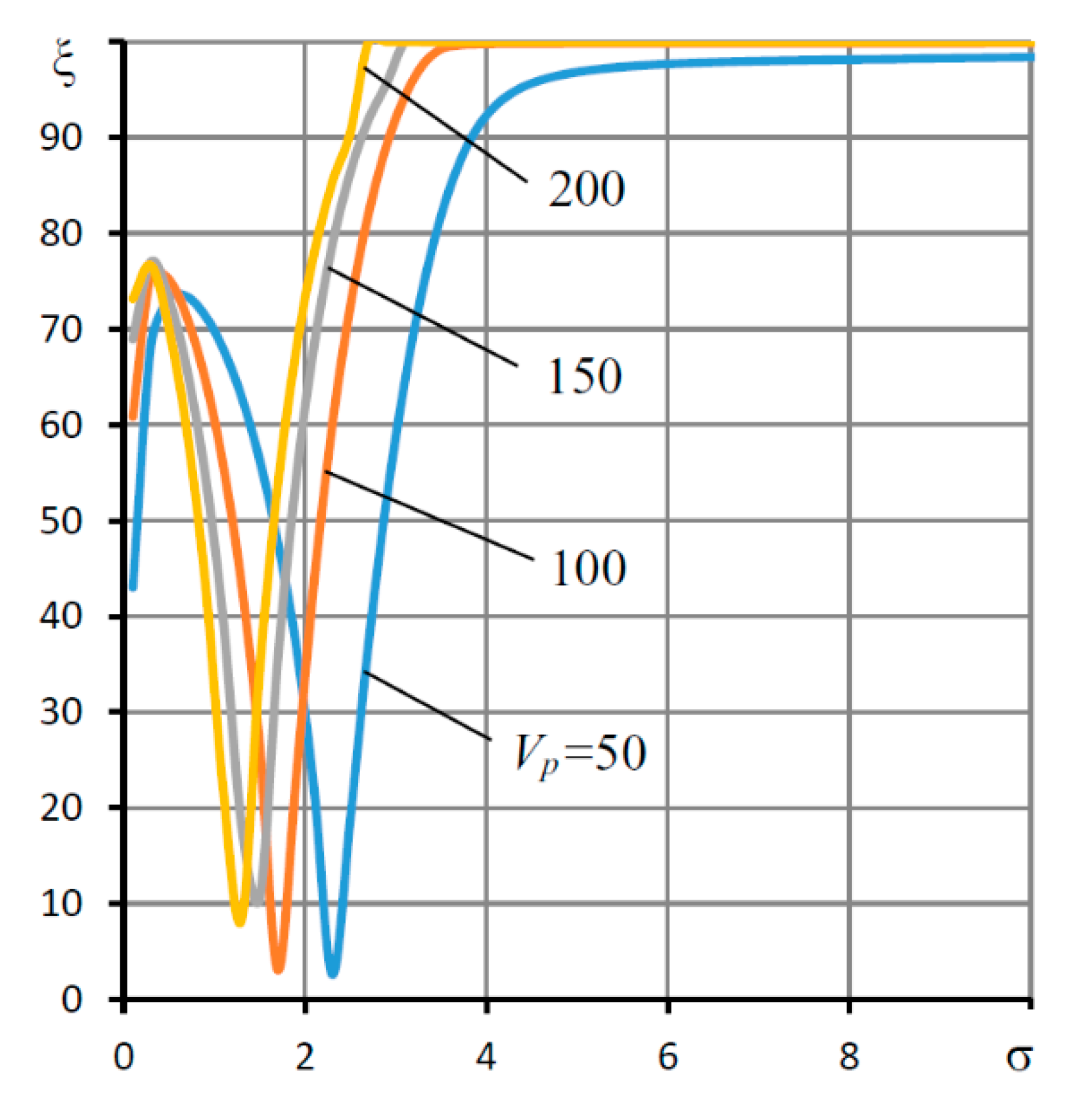
First of all, we studied the influence of the weight coefficient ς of the SECT on the bearing dynamics, because, as shown in the study of the static characteristics, its value should be small. To ensure negative compliance, the bearing must satisfy the condition ς < ςc, where, as follows from Figure 3, for this combination of parameters, ςc ≈ 0.554. Figure 11 shows the dependence of the speed criterion η on ς, and Figure 12—criterion of the fluctuations ξ.
As can be seen from the graph in Figure 11, the bearing has the best speed (maximum value of the criterion η) at different Vp in the range 0.1 < ς < 0.3, i.e., in the region ς < ςc, where a decrease in compliance to zero and negative values can be ensured. It is noteworthy that the speed of the bearing combined with external throttling is many times higher than in the bearing with single throttling by annular diaphragms (ς = 1). In this case, a single-throttle bearing with simple diaphragms (ς = 0) turned out to be expectedly unstable (η < 0), because such a bearing can be stable only for those values of the volume Vp that are comparable or less than the volume of the carrier air gap (Vp < 1) [32], which cannot be ensured in the design under study for design reasons. The graph shows that the best performance of a bearing with the SECT is observed when the volume of the inter-throttle chamber is one to two orders of magnitude greater than the volume of the supporting air gap. This is quite consistent with the recommendations regarding the values of this parameter for aerostatic bearings with passive and active double throttling [26,27].
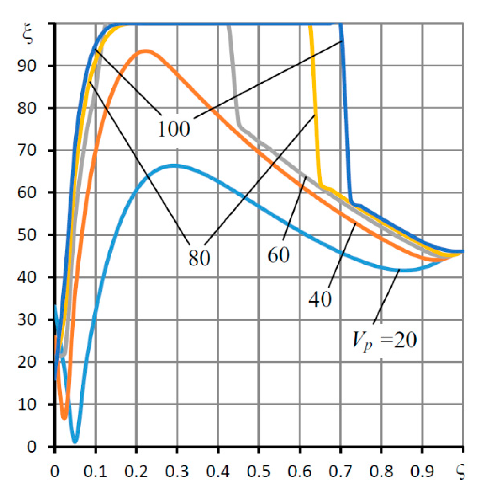
Figure 12 represents the dependences of the criterion of damping of the oscillations for the period ξ on ς and shows that, at small values of the volume Vp, the transient process has an oscillatory character (ξ < 100%).
However, with an increase in volume at Vp > 40, regions appear on the curves that correspond to the aperiodic nature of the transient processes (ξ = 100%), which indicates an increase in the bearing stability margin to an ideal level. A comparison of the graphs in Figure 11 and Figure 12 shows that the change in the character of the transient characteristic from oscillatory to aperiodic occurs at the point ς = ςopt of the maximum of the function η(ς). For ς < ςopt, the transient characteristic is oscillatory, and for ςopt ≤ ς ≤ ςlim, it is aperiodic, where ςlim is the limiting value of the coefficient ς; at which point, the transient characteristic again changes its character to the opposite—from aperiodic to oscillatory. Thus, the volume of the inter-throttle chambers is an important factor in improving the dynamic characteristics of the bearing with the SECT. This is the fundamental difference between the effect of the air volumes in the flow path of aerostatic bearings with the SECT from conventional bearings with single throttling, in which the volume of cavities should be minimized in order to improve the dynamics quality.
As can be seen from the graphs, the larger the volume Vp of the inter-throttle chambers, the wider the range of values of the parameter ς, in which the bearing has a high damping and the stability margin is sufficient to suppress the oscillation of the transient characteristics.
Of interest is the dynamic characteristics of the bearing in the space of the variations of the parameters Vp and σ, which only affect the dynamics of the bearing. The corresponding graphs are shown in Figure 13 and Figure 14.
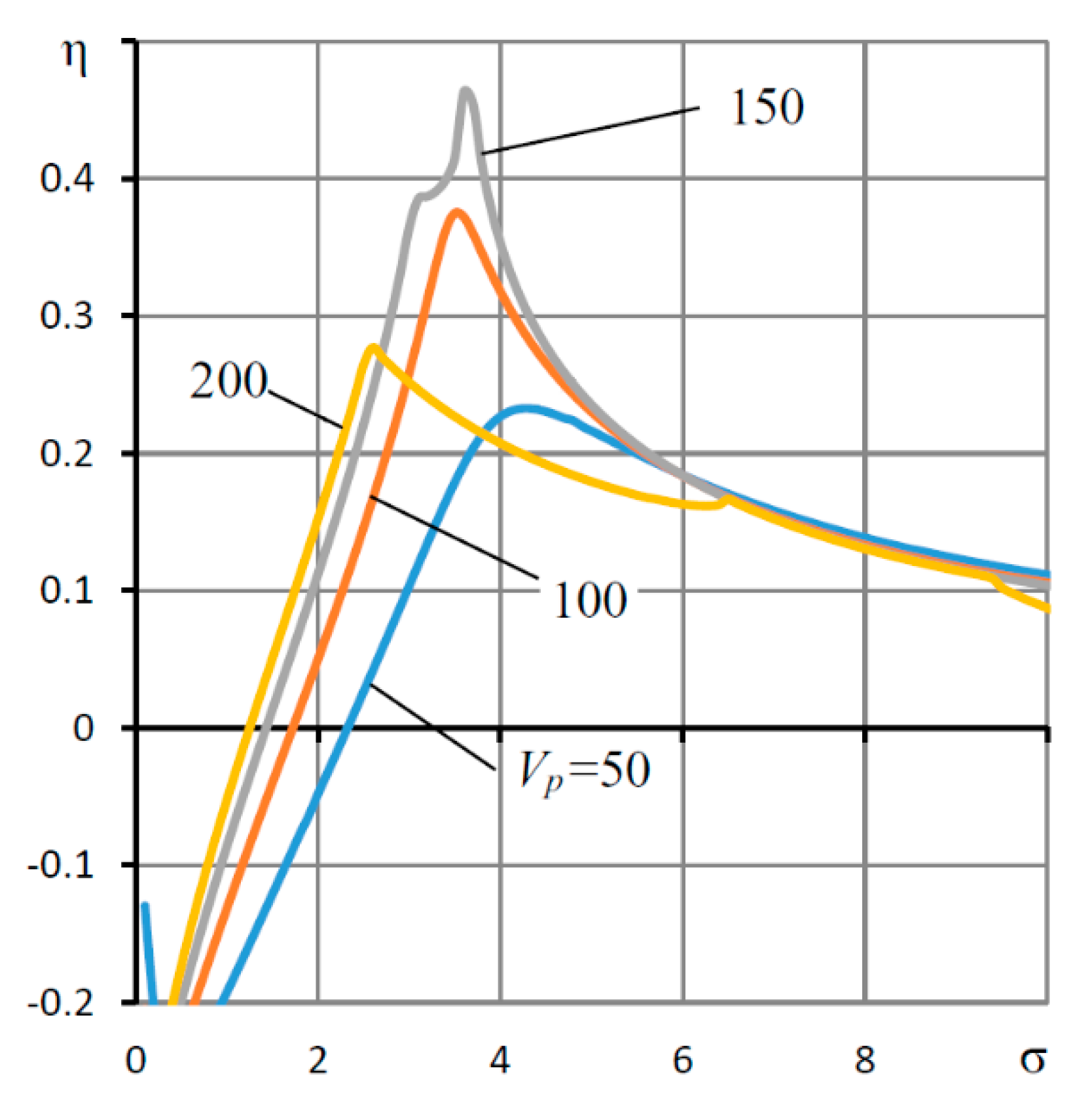
The graph in Figure 13 confirms the well-known conclusion that the dependences η(σ) for aerostatic bearings of any type are usually extreme [26,27]. This means, in particular, that, in the design mode, there is an optimal dimensional gap h0 from the point of view of stability and speed.
A comparison of the graphs in Figure 13 and Figure 14 shows that the best dynamic characteristics take place at σ ≥ σopt, where σopt is the value of the parameter σ, at which the system reaches its maximum performance. These values of the parameter near the optimum σ = σopt of the function η(σ) correspond to a high response rate and aperiodic character of transient processes (ξ = 100%).
As follows from the graphs in Figure 14, by analogy with ξ(ς), the dependences ξ(σ), starting from a certain volume Vp, reach the limiting value ξ = 100% at Vp > 60. The only difference is that the aperiodic character on such curves (ξ = 100%) takes place in the entire region σ ≥ σopt. In this case, the greater the Vp, the less the σopt. Therefore, the gap h0 is larger.
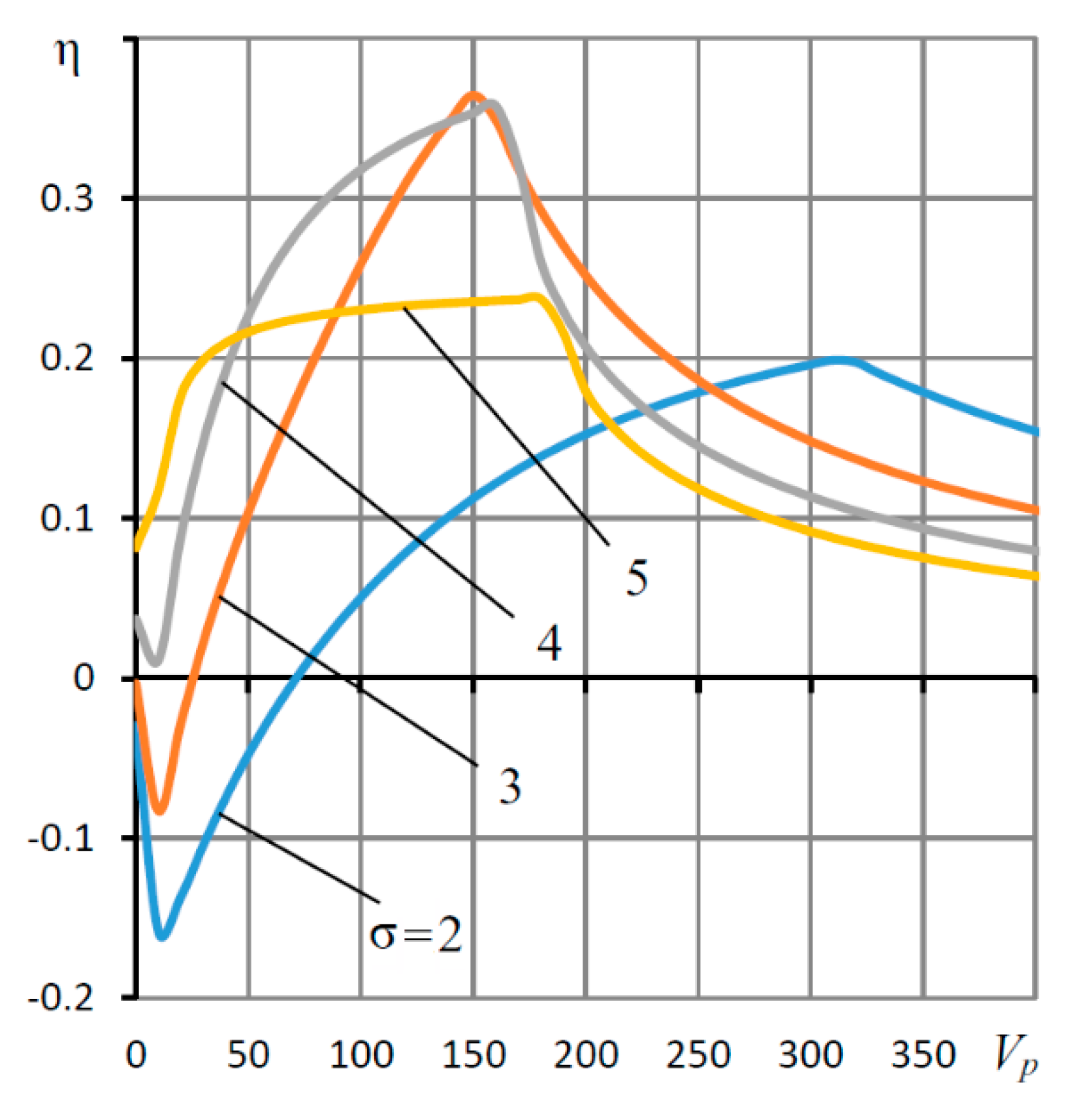
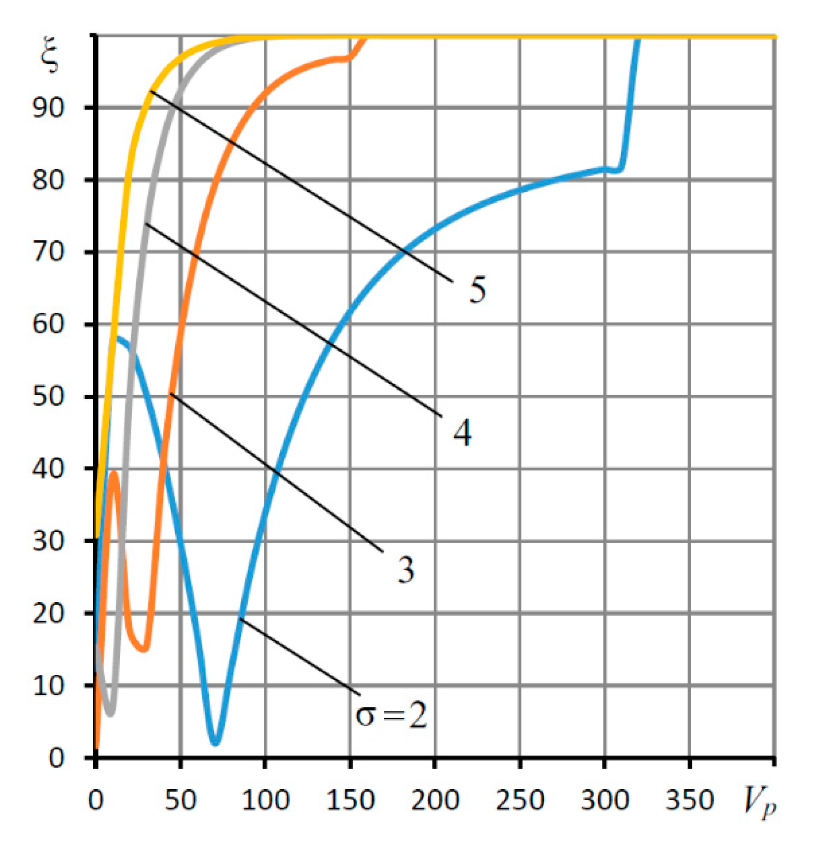
The curves for η(Vp) and ξ(Vp) shown in Figure 15 and Figure 16 are similar to η(σ) and ξ(σ). For them, there are also optimal values of the parameter Vp in terms of the speed Vp opt at which the function η(Vp) reaches its maximum. At Vp < Vp opt, the ξ criterion indicates the oscillatory nature of the transient processes (ξ < 100%), while, at Vp > Vp opt, the transients become aperiodic (ξ = 100%). It is also seen that, with an increase in Vp, the region of aperiodicity of the transient processes expands—that is, an increase in the volume Vp contributes to an increase in the stability margin of the bearing as a dynamic system.
The analysis of the dependences for the performance criteria η and the oscillation of transient processes ξ shows that, in the space of changes in the parameters ς, σ and Vp, for each of which, the criterion η has an optimal value, and the criterion ξ reaches its maximum ξ = 100%; with other fixed parameters, there is the global maximum of the speed function ηmax = η(ς,σ,Vp). The optimization of the η criterion showed that, for these parameters, ηmax = 0.71 at ςmax = 0.149, σmax = 3.48 and Vp max = 139. In practical terms, when designing a bearing, it is recommended to choose slightly larger values: ς = 0.15, σ = 3.5 and Vp = 140, since, at these values, the speed will be close to optimal, and the transient response will be aperiodic, providing a sufficient stability margin.
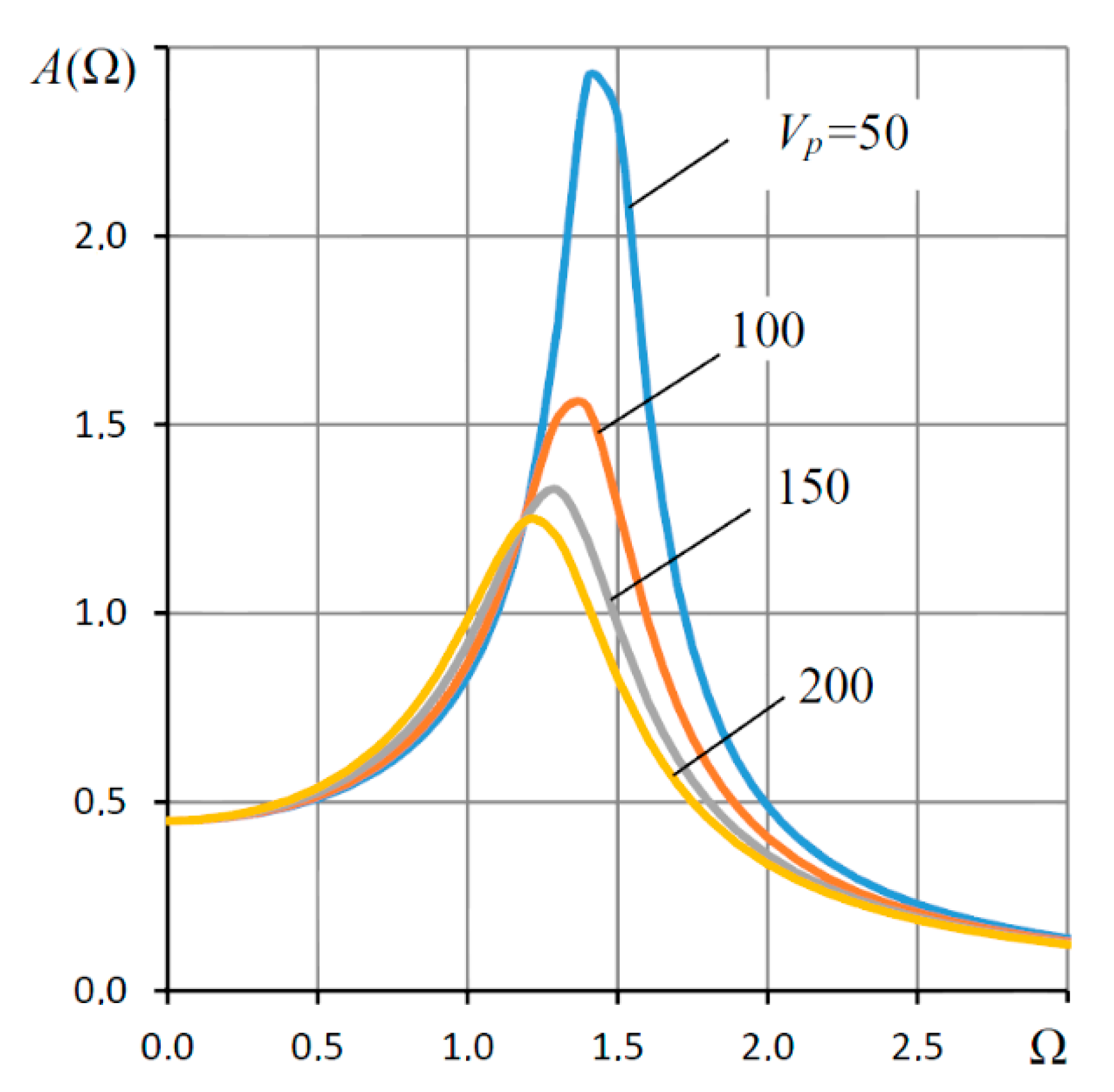
Figure 17 shows the amplitude-frequency characteristics of the bearing with the throttle SECT. As can be seen from the graph, an increase in Vp contributes to a noticeable decrease in the resonance peaks A(Ω), which also indicates that the Vp parameter is an important factor in increasing the stability margin of a bearing with a throttle SECT.
The parameter σ in the region of optimality of the criteria η and ξ barely affects the frequency characteristics of the bearing.

6. An Example of Calculating the Dimensional Characteristics of a Bearing and their Experimental Validation

Let us give an example of calculating the dimensional characteristics of a bearing with a throttle SECT for ς = 0.15, σ = 3.5 and Vp = 140.
For the calculation and subsequent experimental verification, we take the bearing radius r0 = 15·10−3 m and the ambient pressure pa = 0.1·106 Pa used in [40]. As seen from Figure 9, the maximum dimensionless support load Fmax = 1.05; therefore, the maximum load f m a x = 2 π r 0 2 p a F m a x = 148   N .
Using the expression for the dimensionless mass of the shaft at Mas = 1, we find the formula for calculating the scale of the current time:
t 0 = 1 r 0 m s h 0 2 π p a .
Substituting (109) into the expression for the squeezing number σ, we obtain the formula for calculating the gap at the design point:
h 0 = r 0 2 π r 0 m s p a ( 12 μ σ ) 2 5 .
Taking the mass of the shaft ms = 1 kg and the viscosity of the air μ = 17.2·10−6 Pa·s, using Formula (110), we calculate the gap h0 = 17·10−6 m. Using Formula (109), we find the scale of the current time t0 = 0.35·10−3 s. The well-known formula [33] for determining the duration tp of the decay of the transient response at η = 0.7 gives t p = 3 t 0 η = 1.5 10 3 s .
For experimental verification of the obtained formulas, the bearing capacity, compliance and rigidity were found and compared with the data of [40]. For a correct comparison, the parameter of the relative spreading of the pressurization lines λ1 = 0.5 was adopted. The comparative data are shown in Table 1.
As can be seen from the table, in general, the experimental and theoretical data are in satisfactory agreement. The theoretical bearing capacity is slightly higher than the experimental data. This is probably because the theoretical model is based on the assumption that discrete feeders can be replaced with a continuous pressurization line. As we can see, this assumption gives an error of no more than 10%, which can be recognized as a completely satisfactory agreement between the theory and experiment. This tendency is also observed when comparing the stiffness characteristics for L = 1.5. For L = 1.0, on the contrary, the theoretical rigidity turned out to be less than the experimental one. However, in general, the error turned out to be insignificant, and the coincidence of the data can also be considered satisfactory.

7. Conclusions

The paper considered an aerostatic radial bearing with an external combined throttling system and an elastic displacement compensator, which was an alternative to aerostatic bearings with air flow compensators. Bearings of both types represented a relatively new generation of aerostatic bearings of low, zero and negative compliance, which, along with the main function, had the ability to automatically compensate for the deformation of the technological system of the machine in order to reduce the time and improve the accuracy and quality of the metalworking.
The results of mathematical modeling and theoretical research of stationary and nonstationary operation modes of bearings with slotted and diaphragm SECT were presented. A counter-matrix sweep method was proposed for solving a linear boundary-value problem in partial derivatives with respect to the function of the pressure square in the bearing gap and inter-throttling cavities of a bearing with a slotted SECT for any values of the relative shaft eccentricity. The method was extended to the solution of a similar nonlinear boundary value problem for a bearing with a throttle SECT, which was obtained by the Seidel iterative method. The efficiency of the developed methods was shown in the examples of calculating the static characteristics of the bearings with the mentioned types of the SECT. A numerical method was proposed for calculating the dynamic quality criteria and the transfer function of the bearing’s dynamic compliance as a linear automatic control system with distributed parameters. An experimental verification of the theoretical characteristics of the bearing was carried out, which showed a satisfactory agreement between the compared data.
It was shown that, with comparable compliance, bearings with throttle SECT surpassed similar slot bearings in terms of load capacity. In addition, the load characteristics of throttle bearings were much more stable.
It was established that there was a possibility of the optimal determination of the SECT setting by weighting factor values, the squeezing number and the volume of the inter-throttle chambers, which provided the bearing with the optimal performance and a high stability margin. It was shown that bearings with an elastic suspension of the movable sleeve allowed to compensate for significant displacements, which can be larger than the size of the air gap by an order of magnitude or more, when similar bearings with air flow compensators were obviously inoperative.
Thus, the considered aerostatic radial bearing with active displacement compensation can find practical application as a better replacement for conventional aerostatic bearings and bearings with active air flow rate compensators.

Author Contributions

Conceptualization, V.K.; formal analysis, A.K.; investigation, S.S., I.P. and Y.P.; data curation, M.B. and L.S.; writing—original draft preparation, V.K.; writing—review and editing, A.K. and project administration, A.K. All authors have read and agreed to the published version of the manuscript.

Funding

This research received no external funding.

Institutional Review Board Statement

Not applicable.

Informed Consent Statement

Not applicable.

Data Availability Statement

The data presented in this study are available upon request from the corresponding author. The data are not publicly available due to privacy.

Conflicts of Interest

The authors declare no conflict of interest.

Nomenclature

dkdiameter of damping diaphragms
dpdiameter of throttling diaphragms of elastic orifices
H, h, h0dimensionless thickness, current thickness of the gap and its thickness for ε = 0
Kdimensionless compliance of bearing
Kedimensionless compliance of the suspension 6
l, Lhalf of the length and dimensionless length of bearing
l1, L1half of the length and dimensionless length of the inter-row part
l2, L2length and dimensionless length of end parts
mas, Masmass and dimensionless mass of the shaft
P(Z,φ,τ)dimensionless dynamic pressure in the carrier gap
P0(Z)dimensionless static pressure in the carrier gap for ε = 0
paambient pressure
pkpressure of air on damping diaphragms
pppressure of air in inter-throttle chambers
pssupply pressure
Qhdimensionless flow rate through the gap
Qkdimensionless flow rate through damping diaphragms
Qpdimensionless flow rate through elastic orifices
Qvdimensionless flow rate associated with compressibility of air in the inter-throttle chambers
r0the shaft radius
sthe Laplace transform variable
t0the scale of current time
vp, Vpvolume of inter-throttle chambers and their dimensionless volume
Wdimensionless bearing capacity
Zdimensionless longitudinal coordinate
εdimensionless eccentricity
φdimensionless circumferential coordinate
τdimensionless current time
μcoefficient of dynamic viscosity of the air
ηdegree of stability
ξcriterion of oscillations damping over a period
σthe “squeezing number”
χnormalized adjustment coefficient of the external throttling system
ςnormalized adjustment coefficient of annular damping diaphragms
Π ( P 1 , P 2 ) the Prandtl function

References

  1. Lian, H.; Wu, H.; Li, Y.; Rong, C. New Start-up Method for a Closed-Cycle Compression System with Gas Bearings and Its Characteristics. Chin. J. Mech. Eng. 2020, 33, 1–16. [Google Scholar] [CrossRef]
  2. Ishibashi, K.; Kondo, A.; Kawada, S.; Miyatake, M.; Yoshimoto, S.; Stolarski, T. Static and dynamic characteristics of a downsized aerostatic circular thrust bearing with a single feed hole. Precis. Eng. 2019, 60, 448–457. [Google Scholar] [CrossRef]
  3. Gao, Q.; Chen, W.; Lu, L.; Huo, D.; Cheng, K. Aerostatic bearings design and analysis with the application to precision engineering: State-of-the-art and future perspectives. Tribol. Int. 2019, 135, 1–17. [Google Scholar] [CrossRef]
  4. Huang, M.; Xu, Q.; Li, M.; Wang, B.; Wang, J. A calculation method on the performance analysis of the thrust aerostatic bearing with vacuum pre-load. Tribol. Int. 2017, 110, 125–130. [Google Scholar] [CrossRef]
  5. Nishio, U.; Somaya, K.; Yoshimoto, S. Numerical calculation and experimental verification of static and dynamic characteristics of aerostatic thrust bearings with small feedholes. Tribol. Int. 2011, 44, 1790–1795. [Google Scholar] [CrossRef]
  6. Viktorov, V.; Belforte, G.; Raparelli, T. Modeling and Identification of Gas Journal Bearings: Externally Pressurized Gas Bearing Results. J. Tribol. 2005, 127, 548–556. [Google Scholar] [CrossRef]
  7. Blondeel, E.; Snoeys, R. Externally Pressurised Bearing with Pressure Dependent Restrictors. In Proceedings of the 6th International Gas Bearing Symposium, Southampton, UK, 1 December 1974; BHRA Fluid Engineering: Cranfield, UK, 1974; pp. D2-19–D2-41. [Google Scholar]
  8. Lai, T.-H.; Chang, T.-Y.; Yang, Y.-L.; Lin, S.-C. Parameters design of a membrane-type restrictor with single-pad hydrostatic bearing to achieve high static stiffness. Tribol. Int. 2017, 107, 206–212. [Google Scholar] [CrossRef]
  9. Kang, Y.; Shen, P.-C.; Chang, Y.-P.; Lee, H.-H.; Chiang, C.-P. Modified predictions of restriction coefficient and flow resistance for membrane-type restrictors in hydrostatic bearing by using regression. Tribol. Int. 2007, 40, 1369–1380. [Google Scholar] [CrossRef]
  10. Kodnyanko, V.; Shatokhin, S.; Kurzakov, A.; Pikalov, Y. Theoretical analysis of compliance and dynamics quality of a lightly loaded aerostatic journal bearing with elastic orifices. Precis. Eng. 2021, 68, 72–81. [Google Scholar] [CrossRef]
  11. Newgard, P.M.; Kiang, R.L. Elastic Orifices for Pressurized Gas Bearings. ASLE Trans. 1966, 9, 311–317. [Google Scholar] [CrossRef]
  12. Shatokhin, S.N.; Kodnyanko, V.A. Load and flow rate characteristics of an axial pressurized gas bearing with an active compensation of gas flow. In Mechanical Sciences; Springer Nature: Berlin/Heidelberg, Germany, 2017; pp. 110–115. [Google Scholar]
  13. Kodnyanko, V.A.; Pikalov, Y.A.; Shatokhin, S.N. Investigation of the characteristics of a gas-static bearing with active flow rate compensation. Bull. Mech. Eng. 1979, 4, 9–12. [Google Scholar]
  14. Singh, N.; Sharma, S.C.; Jain, C.; Reddy, S.S. Performance of membrane compensated multirecess hydrostatic/hybrid flexible journal bearing system considering various recess shapes. Tribol. Int. 2004, 37, 11–24. [Google Scholar] [CrossRef]
  15. Shatokhin, S.N.; Kodnyanko, V.A. Radial gasostatic bearing-seal with opposite internal gas flow compensation. Sov. J. Frict. Wear 1984, 5, 118–123. [Google Scholar]
  16. Kodnyanko, V.A. Characteristics of a gas-static thrust bearing with an active displacement controller. Mosc. J. Metal Cut. Mach. Tools 2005, 9, 32–34. [Google Scholar]
  17. Dambrauskas, A.P.; Shatokhin, S.S.; Shatokhina, L.P. Research and optimization of dynamic characteristics of a radial hydrostatic bearing with a movable sleeve. Probl. Mech. Eng. Reliab. Mach. 1993, 1, 12–18. [Google Scholar]
  18. Kurzakov, A.S.; Shatokhin, S.N. Analysis of Methods of Theoretical Research and Calculation of Adaptive Aerostatic Spindle Bearings. Stanki Instrum. 2003, 5, 7–11. (In Russian) [Google Scholar]
  19. Shatokhin, S.N.; Skvortsov, A.G.; Shatokhina, L.V. Closed hydrostatic guides with built-in floating regulators of adaptive grease injection. Technol. Mech. Eng. 2010, 3, 31–35. [Google Scholar]
  20. Kodnyanko, V.A.; Kurzakov, A.S. Static characteristics of hydrostatic thrust support with a membrane displacement compensator. Russ. Bull. Mech. Eng. 2017, 8, 66–70. [Google Scholar]
  21. Kodnyanko, V.A. Characteristics of a gas-static thrust bearing with an active displacement regulator. Russ. J. STIN 2005, 9, 32–34. [Google Scholar]
  22. Stepanyants, L.G.; Zablotsky, N.D.; Sipenhov, I.E. Method of Theoretical Investigation of Externally Pressurized Gas-Lubricated Bearings. J. Lubr. Technol. 1969, 91, 166–170. [Google Scholar] [CrossRef]
  23. Zablotskii, N.D.; Karpov, V.S. Characteristics of pressurization devices of gas bearings. Izv. Akad. Nauk SSSR Mekh. Zhid. Gasa 1973, 2, 143–149. (In Russian) [Google Scholar]
  24. Pinegin, S.V.; Tabachnikov, Y.B.; Sipenkov, I.E. Statistical and Dynamic Characteristics of Gas-Static Supports; Science: Moscow, Russia, 1982; p. 264. [Google Scholar]
  25. Constantinescu, V.N. Gas Lubrication; The American Society of Mechanical Engineers: New York, NY, USA, 1969; 709p. [Google Scholar]
  26. Kodnyanko, V.A.; Shatokhin, S.N. Theoretical study on dynamics quality of aerostatic thrust bearing with external combined throttling. FME Trans. 2020, 48, 342–350. [Google Scholar] [CrossRef]
  27. Kodnyanko, V.; Shatokhin, S.; Kurzakov, A.; Pikalov, Y. Mathematical Modeling on Statics and Dynamics of Aerostatic Thrust Bearing with External Combined Throttling and Elastic Orifice Fluid Flow Regulation. Lubricants 2020, 8, 57. [Google Scholar] [CrossRef]
  28. Samarsky, A.A. Introduction to the Theory of Difference Schemes; Science: Moscow, Russia, 1971; p. 553. (In Russian) [Google Scholar]
  29. Demidovich, B.P.; Maron, I.L.; Shuvalova, E.Z. Numerical Methods for Analysis: Approximation of Functions, Differential and Integral Equations; Lan: Moscow, Russia, 2010. (In Russian) [Google Scholar]
  30. Samarskiy, A.A.; Nikolaev, E.S. Methods for Solving Grid Equations; Nauka: Moscow, Russia, 1978. (In Russian) [Google Scholar]
  31. Stroud, A.H. Approximate Calculation of Multiple Integrals; Prentice-Hall: Englewood Cliffs, NJ, USA, 1971. [Google Scholar]
  32. Dwight, H. Tables of Integrals and Other Mathematical Data; The Macmillan Company: New York, NY, USA, 1961. [Google Scholar]
  33. Kodnyanko, V. Directional Splines for Economic Analytics. Econ. Comput. Econ. Cybern. Stud. Res. 2020, 54, 129–144. [Google Scholar] [CrossRef]
  34. Anita, H.M. Numerical Methods for Scientists and Engineers; Hindustan Book Agency: New Delhi, India, 2012; 855p. [Google Scholar] [CrossRef] [Green Version]
  35. Besekersky, V.A.; Popov, E.P. Theory of Automatic Control Systems; Springer Professional: St. Petersburg, Russia, 2003; p. 752. [Google Scholar]
  36. Smith, S.W. The Discrete Fourier Transform. In The Scientist and Engineer’s Guide to Digital Signal Processing, 2nd ed.; California Technical Publishing: San Diego, CA, USA, 1999. [Google Scholar]
  37. Press, W.H.; Teukolsky, S.A.; Vetterling, W.T.; Flannery, B.P. Numerical Recipes: The Art of Scientific Computing, 3rd ed.; Cambridge University Press: Cambridge, UK, 2007. [Google Scholar]
  38. Golub, G.H.; Van Loan, C.F. Matrix Computations. In John Hopkins Studies in the Mathematical Sciences; Johns Hopkins University Press: Baltimore, MD, USA, 1996. [Google Scholar]
  39. Blahut, R.E. Fast Algorithms for Signal Processing; Cambridge University Press: Cambridge, UK, 2010; p. 469. [Google Scholar] [CrossRef]
  40. Šimek, J.; Kozanek, J.; Steinbauer, P. Dynamic Properties of Aerostatic Journal Bearings, Colloquium Dynamics of Machines; Institute of Thermomechanics: Prague, Czech Republic, 2007. [Google Scholar]
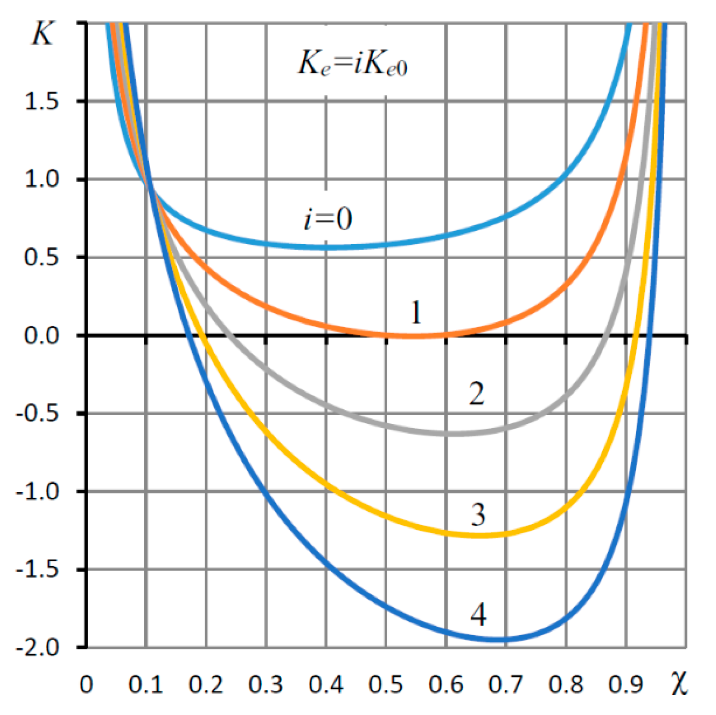
Figure 2. Dependences of the compliance K of the slotted feeder bearing on the coefficient χ of the system of external combined throttling (SECT) for different values of the elasticity coefficient Ke.
Applsci 11 02623 g002
Figure 3. Dependences of the compliance K of the slotted feeder bearing on the weight coefficient ς SECT for different values of the elasticity coefficient Ke.
Applsci 11 02623 g003
Figure 4. Dependences of the compliance K of the slotted feeder bearing on the coefficient χ of the SECT for various values of the elasticity coefficient Ke.
Applsci 11 02623 g004
Figure 5. Dependencies of the functions Uk(χ) and Up(χ) for the bearing with the slot (1) and diaphragm (2) feeders of the SECT.
Applsci 11 02623 g005
Figure 6. Dependences of the compliance K of the bearing with throttling feeders on the weight coefficient ς SECT for different values of the coefficient of elasticity Ke.
Applsci 11 02623 g006
Figure 7. Dependences of the total eccentricity εs of the slotted SECT on the external load F for different values of the elasticity coefficient Ke.
Applsci 11 02623 g007
Figure 8. Comparative nonlinear (solid curves) and linear (dashed straight lines) dependences of the total eccentricity εs of the slotted SECT on load F for different values of the elasticity Ke.
Applsci 11 02623 g008
Figure 9. Dependences of the total eccentricity εs of the throttle SECT on the external load F for different values of the coefficient of elasticity Ke.
Applsci 11 02623 g009
Figure 10. Comparative nonlinear (solid curves) and linear (dashed straight lines) dependences of the total eccentricity εs of the throttle SECT on the external load F for different values of the elasticity coefficient Ke.
Applsci 11 02623 g010
Figure 11. Dependences of the degree of stability η of the bearing with the throttle SECT on the coefficient ς and volume Vp, σ = 4.
Applsci 11 02623 g011
Figure 12. Dependences of the criterion for the damping oscillations for the period ξ of the bearing with the throttle SECT on the coefficient ς and volume Vp, where σ = 4.
Applsci 11 02623 g012
Figure 13. Dependences of the degree of stability η of a bearing with a throttle SECT on the squeezing number σ.
Applsci 11 02623 g013
Figure 14. Dependences of the criterion of damping of the oscillations for the period ξ of the bearing with the throttle SECT on the squeezing number σ and volume Vp, where ς = 0.15.
Applsci 11 02623 g014
Figure 15. Dependences of the degree of stability η of a bearing with a throttle SECT on the volume Vp and the squeezing number σ, where ς = 0.15.
Applsci 11 02623 g015
Figure 16. Dependences of the criterion of damping of oscillations for the period ξ of the bearing with a throttle SECT on the volume Vp and squeezing number σ, where ς = 0.15.
Applsci 11 02623 g016
Figure 17. Amplitude–frequency characteristics of a bearing with a throttle SECT for different values of the volume Vp, ς = 0.15, where σ = 4.5.
Applsci 11 02623 g017
Table 1. Comparative bearing characteristics at the relative eccentricity ε = 0.5.
L = l/r0,
h0 (mm)
Supply Pressure ps (MPa)Load Capacity
(N)
Stiffness ( N m 1 )
ExperimentTheoryExperimentTheory
1.5,
0.0225
0.364691.0·1071.2·107
0.51051121.5·1071.6·107
1.0,
0.015
0.328311.5·1071.4·107
0.572762.0·1071.8·107
Publisher’s Note: MDPI stays neutral with regard to jurisdictional claims in published maps and institutional affiliations.