Abstract
In this study, an experiment on compressive strength of the hybrid concrete-filled fiber-reinforced polymer (FRP) tube (CFFT) confined by filament winding was conducted to improve the longitudinal strength while considering the thickness of filament winding as a variable. A maximum error of 17% was observed when the results of performing the finite element analysis (FEA) by applying the mechanical properties of the fiber-reinforced polymer (FRP) materials suggested in previous studies were compared to those of the compressive strength experiment on the hybrid-CFFT. Moreover, a maximum error of 15% was exhibited when the results derived from the strength equation proposed by analyzing the compressive strength experiment were compared. Furthermore, the compressive strength of the hybrid-CFFT increased by up to 14% when the longitudinal compressive strength of the pre-tensioned spun high strength concrete (PHC) pile and concrete-filled tube (CFT) were compared.
1. Introduction
Structural steel and concrete are used as major construction materials owing to their excellent economic feasibility and durability. However, over time, concrete becomes neutralized, and the structural steel corrodes due to exposure to various harmful environments. Thus, structural durability is significantly reduced, causing significant economic losses in terms of repair and reinforcement of piles. When structural steel or concrete piles are exposed to high-humidity and high-salinity environments, such as in harbors, enormous economic losses from maintenance are incurred for improving the durability. In a study conducted in the United States, Lampo et al. [1] reported that more than USD 1 billion is spent annually on repair and reinforcement of piles [2].
Fiber-reinforced polymer (FRP), which is a type of construction material, has been manufactured and used as a repair and reinforcement material since the 1970s in the United States, Canada, Japan, and Europe; bridges have been constructed with FRP since the 1990s. In Korea, the FRP manufacturing technology has also rapidly advanced along with an increased utilization of FRP in the construction industry since the 1990s. However, the application of FRP members in these areas is limited due to the lack of design standards as well as structural behavior prediction and analytical methods. Certain design formulas for the FRP members devised under specific loads and boundary conditions have not undergone sufficient experimental verification due to many different variables of design and analysis. Thus, FRP members are subjected to independent experiments for verifying the performance before applying to structures with limitations.
FRP piles developed by protecting the exterior of concrete with FRP have recently been studied extensively to improve the durability and axial load performance. A concrete-filled tube (CFT) in which a circular or angular steel pipe is filled with concrete has outstanding properties in terms of rigidity, strength, fire resistance, and constructability of the entire member because the concrete is confined by the steel pipe. The first application of the CFT in the construction industry was the pier of the Severn Railway Bridge in England, which was completed in 1879. Later in 1901, Sewell verified that the rigidity increases if steel pipes are filled with concrete for preventing internal corrosion [3]. Richart et al. developed an equation for predicting the increase in axial compressive strength of concrete confined by a cylinder through an experiment using a concrete test piece [4]. Morales et al. conducted an experiment on the compressive strength of concrete confined by spiral reinforcements per concrete strength, and confirmed that the ratio of longitudinal to axial strain decreases as the confinement effect increases [5]. Iyengar et al. conducted an experiment on compressive strength by adjusting the distance among spiral reinforcements, which is a concrete reinforcement material, from 30 to 118 mm [6]. The confinement effectiveness coefficient, which signifies the confinement characteristics, was obtained from experimental results. It was confirmed that the increase in compressive strength is due to the confinement of the spiral reinforcements. Wei et al. [7] examined 491 previous studies on the compressive strength of CFT and proposed a hoop stress model of CFT.
Moreover, extensive research is being conducted on concrete-filled FRP tubes (CFFTs) in which FRP is used as a material for confining concrete by expanding the CFT structure.
In this regard, Nanni et al. [8] and Toutanji [9] verified the increase in the strength of FRP by conducting experiments on the compression of CFFT. Picher et al. [10] conducted an experiment on the compression of short concrete columns confined by CFRP sheets to predict the behavior of concrete under multi-axial loads and verified that the compressive strength varies when the thickness of the CFRP sheet and fiber orientation are adjusted. Chan et al. [11] conducted an experiment on a concrete compression member confined by spiral reinforcements and verified that the axial strength and ultimate strain of the confined concrete member increased by approximately 50% and 70%, respectively, compared to those of unconfined concrete. Zhu et al. investigated the effect of column parameters on the axial compression behavior of CFFT [12]. Tian et al. investigated the axial compressive behavior of a glass FRP tube filled with ultra-high performance concrete [13]. Gao et al. [14] presented a new concrete-filled FRP tube (CFFT) with an inner steel wire mesh (WM). By conducting a compression test of the CFFT-WM, it was confirmed that the predicted values for compressive strength and strain were consistent with the experimental results.
The compressive strength of CFFT can be expected to increase due to confinement because filament winding is used in which the reinforcing fiber is arranged in a circumferential direction. However, the member can also be vulnerable to bending and shear stresses due to an eccentric compressive load. To secure the stability against flexural and shear behavior, a reinforcement material, such as a rebar, is required in the FRP-concrete composite member. In this study, therefore, the compressive strength of the hybrid−CFFT, a dual-structured composite material, was tested by manufacturing a modular pultrusion FRP member in which the reinforcing fiber was arranged in the axial and circumferential directions, and the exterior was reinforced with filament winding FRP (FFRP). An experiment on the compressive strength of the hybrid−CFFT was conducted and, based on the thickness of FFRP, a strength equation was proposed by analyzing the experimental results.
2. Theoretical Background
The compressive strength ratio of confined concrete to unconfined concrete derived from the experiment on concrete confined using structural steel and proposed by Richart et al. is presented in Equation (1) [15]. Based on the experimental research by several researchers [9,16,17,18,19], Equation (1) has been proven to be applicable for predicting the strength of concrete confined by FRP.
where, fcc is compressive strength of confined concrete, fco is that of unconfined concrete, k1 is the confinement effective coefficient, and fl is the confining pressure.
According to Richart et al. [15], the confinement effectiveness coefficient k1 is 4.1 if concrete is sufficiently reinforced by the structural steel or when a tie bar is used. However, k1 varies according to the experimental results of different studies when concrete is confined by FRP. The confinement effectiveness coefficients proposed by various studies are summarized in Table 1.

Table 1.
Confinement effective coefficient of concrete-filled fiber-reinforced polymer tube (CFFT), k1.
From Equation (1), k1 presented in Table 1 signifies that the correlation between the strength ratio and the confinement ratio becomes linear if expressed as constants and nonlinear if expressed as a function of the confining pressure and concrete strength. In Table 1, the coefficients proposed by Samaan et al. and Saafi et al. [17,19] are based on the experimental results when a cylindrical FRP tube is filled with concrete, while those proposed by other researchers are based on the experimental results when a concrete column is wrapped with FRP.
The axial confinement of a CFFT tube refers to the pressure generated by the confined material when a transformation occurs in the radial direction as the material expands in the direction orthogonal to the circumferential direction (radial direction) owing to a compressive load. The mechanical behavior of CFFT confinement is determined by the degree of concrete expansion and the strength and rigidity of the confining member suppressing the expansion. When the CFFT tube is under a compressive load, the stress in the radial direction and the confining stress due to the reinforcement become parallel in the ultimate state, as shown in Figure 1, thus establishing the relationship defined in Equation (2).
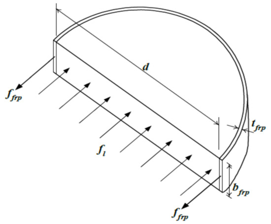
Figure 1.
Confinement effect of fiber-reinforced polymer (FRP).
Here, fl is the confining pressure, fp is the tensile strength in the circumferential direction of the external reinforcement constituting the exterior, t is the reinforcement thickness, and ρp is the volume ratio of the inner concrete to external reinforcement, and d is diameter defined in Equation (3).
The confining pressure (Equation (1)) is expressed as a function of the strength and thickness of the confining material, while the confining effect is influenced by the mechanical properties of the confined and confining materials. The compressive behavior of CFFT is shown in Figure 2. The solid line shows the load–strain correlation of unconfined plain concrete, dotted line the load–strain curve for the axial compressive load of an FRP tube, and dashed line the combined effect of the FRP tube and plain concrete. However, CFFT in which FRP tubes are filled with concrete exhibits the compressive behavior shown by the dashed dotted line owing to the confinement effect in addition to the algebraic sum of the load curves of two materials.
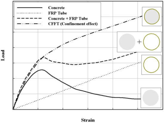
Figure 2.
Compressive behavior of CFFT [21].
3. Compressive Behavior Evaluation of the Hybrid−CFFT
3.1. Mechanical Properties of FRP Materials
A hybrid-CFFT member consists of pultruded FRP (PFRP), filament winding FRP (FFRP), and core concrete. To investigate the structural behavior of the hybrid−CFFT member, experiments were performed to obtain the mechanical properties of the materials prior to the structural behavior study.
- (a)
- Tension Test of PFRP
The tests were performed based on the ASTM D3039/D3039M [22] standard to determine the tensile strength and elastic modulus of the PFRP, and the test specimens were taken from the whole cross-section (i.e., inner arc, outer arc, and rib) of the PFRP member. Test specimens taken from different locations had different layer thicknesses. All specimens were tested with a loading speed of 3 mm/mm; the loads and strains were measured and recorded automatically by the computerized data acquisition system. The test setup is shown in Figure 3.
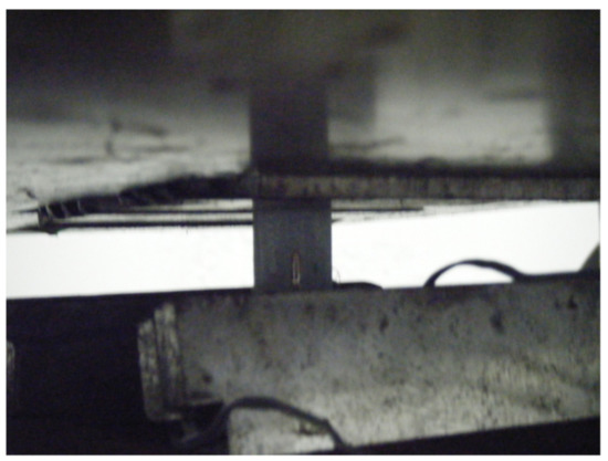
Figure 3.
Tension test setup of pultruded FRP (PFRP).
The test results are shown in Table 2, and they demonstrate that all test specimens failed within a gauge length along the fiber direction. In Table 2, elastic modulus is determined in strain rage of 1000 με to 3000 με, and the average ultimate strength is calculated by eliminating the maximum and minimum values.
Table 2.
Test results of PFRP tensile test.
- (b)
- Tensile Test of FFRP
Tensile tests were also conducted on FFRP. The test specimens were taken from the whole cross-section of the FFRP cylinder, and the test setup is shown in Figure 4.
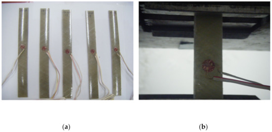
Figure 4.
Setup of the filament winding FRP (FFRP) tensile test: (a) specimen, (b) attachment of strain gauge.
The test results are shown in Table 3, and they show that all the specimens failed within the gauge length along the fiber direction.
Table 3.
Test results of FFRP tensile test.
- (c)
- Split Disk Test of FFRP
The split disk test of FFRP was also conducted according to ASTM D2290 [23]. The split disk test was conducted by using the steel test fixture as shown in Figure 5. The test results are shown in Table 4, and they demonstrate that all the specimens failed in the direction of the fiber distribution.
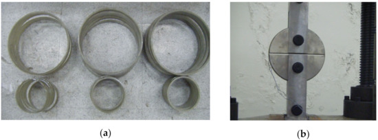
Figure 5.
Setup for the split disk test: (a) specimens, and (b) test setup.
Table 4.
Results of FFRP split disk test.
3.2. Composition and Characteristics of the Hybrid-CFFT
The hybrid-CFFT proposed in this study is a dual-structure composite material in which a modular pultruded FRP (PFRP) member is manufactured wherein reinforcing fibers are arranged in axial and circumferential directions. Then, the exterior of the member is reinforced with FFRP. Figure 6 shows the cross−section of this structure.
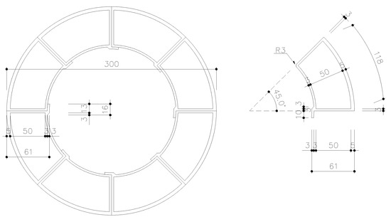
Figure 6.
Cross-section of the hybrid-FRP.
Furthermore, the hybrid-FRP can be produced continuously as there is no limitation in length. Once the exterior is reinforced with FFRP, PFRP resists against bending and shear stress, while the FFRP confines the concrete for improving the axial strength.
As shown in Figure 7a, PFRP modules are manufactured with a pultrusion process and then combined to form a tube. Then, the FRP pile is manufactured by wrapping the tube surface with FFRP using a mandrel, as shown in Figure 7b, which is then transported to the site where concrete is placed.
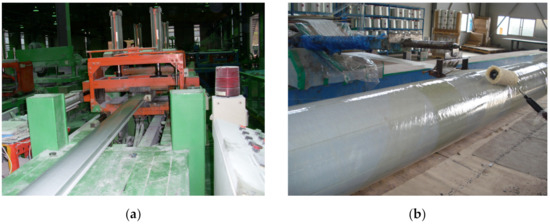
Figure 7.
Manufacturing process of the hybrid−FRP member: (a) pultrusion process; (b) filament winding process.
3.3. Compressive Strength Testing of PFRP-FFRP
To examine the compressive strength of PFRP-FFRP, which affects the compressive strength of the hybrid−CFFT in addition to concrete, the experimental variables of PFRP−FFRP in terms of thickness of FFRP are shown in Table 5. A testing machine that evaluates fatigue durability and can be loaded up to 30,000 kN vertically and 5000 kN horizontally was used. A vertical load of 30,000 kN was applied for the compressive test. A strain gauge was attached to each specimen center in the longitudinal and orthogonal directions, and a displacement gauge with a capacity of 100 mm was installed to measure the compressive displacement in the longitudinal direction. A compression tester with a capacity of 30,000 kN was used to apply the load. The compressive strength test, as shown in Figure 8, was performed according to KS F 2405 [24]. The load was applied at 150 kN/min using a load-controlled method.
Table 5.
Experimental variables of the PFRP−FFRP specimen.
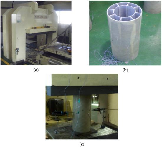
Figure 8.
Compressive strength experiment of PFRP−FFRP. (a) Compression tester with a capacity of 30,000 kN. (b) Experimental PFRP-FFRP specimen of φ300 × 600. (c) Experimental test setup.
The experimental results showed that PFPR−FFPR exhibited three types of fractures: local fracture of the protrusion that connects the PFRP material, interfacial fracture between each FRP member, and simultaneous fractures of PFRP and FFRP. The PFRP-FFRP fractures are presented in Figure 9; the results of compressive strength testing of PFRP−FFRP are also presented in Table 6. Furthermore, the load–displacement and stress–strain relationships obtained from the data measured by the linear variable differential transformer (LVDT) and strain gauge, respectively, are shown in Figure 10 and Figure 11, respectively.
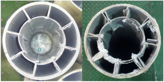
Figure 9.
Fracture mode of PFRP−FFRP.
Table 6.
Compressive strength testing result of PFRP−FFRP.
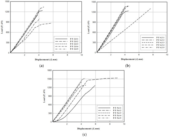
Figure 10.
Load–displacement relationship of PFRP−FFRP. (a) P−F−2.8. (b) P−F−4.2. (c) P−F−5.6.
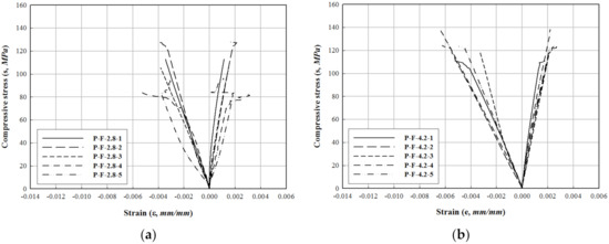
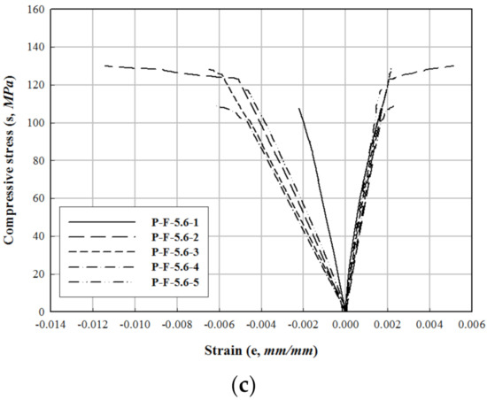
Figure 11.
Stress–strain relationship of PFRP−FFRP. (a) P−F−2.8. (b) P−F−4.2. (c) P−F−5.6.
3.4. Specimen Type and Variables in Compressive Strength Testing of the Hybrid−CFFT
The specimen was manufactured by considering the thickness of the FFRP and the design strength of the inner concrete as variables. Specifically, different thicknesses of FFRP as 2.8 mm (4 ply), 4.2 mm (6 ply), and 5.6 mm (8 ply) were used, with diameter of 300 mm and length of 600 mm. The inner concrete was manufactured with standard design strengths of 21, 30, and 40 MPa based on the mixing ratio in Table 7, thus producing a total of nine specimens. In Table 7, W/b represents the water-binder, S/a the sand-to-aggregate ratio, W the unit weight, b is the amount of additive, C the amount of cement, F/A the amount of admixture per aggregate used, A.D the air entraining and high-range water reducing agent, and S and G the amounts of fine and coarse aggregates, respectively. Table 8 shows the variables of the hybrid−CFFT specimen. The purpose of using additives is to prevent concrete from agglomerating because water-reducing agents or fluidizing agents are added to concrete when filling in pile.
Table 7.
Concrete specific mixing table.
Table 8.
Type and quantity of the hybrid-CFFT specimens.
3.5. Compressive Strength Testing of the Hybrid-CFFT
The specimen for compressive strength testing of the hybrid-CFFT was manufactured as shown in Figure 12. A compression tester with a capacity of 30,000 kN was used to apply the load, as shown in Figure 13. It measured the compressive strength of hybrid-CFFT by applying a load in the vertical direction of the cylindrical pile. The reason is that the strain gauge was attached in the horizontal and vertical directions due to the directionality of the FRP. A guard was manufactured and installed around the specimen to prevent the scattering of the inner concrete during the specimen destruction, and the load was applied at 300 kN/min only to the concrete under a load-controlled condition.
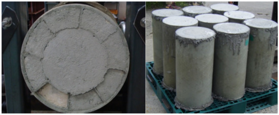
Figure 12.
Specimen for compressive strength testing of the hybrid-CFFT.
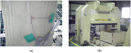
Figure 13.
Compressive strength testing of the hybrid-CFFT: (a) gauge installation and (b) testing equipment.
Testing results (Table 9) showed that the fracture mode was FFRP delamination at the center and upper part of the specimen, as shown in Figure 14a, and strand separation, as shown in Figure 14b. Furthermore, after the specimen was fractured, a portion of the FFRP was removed to inspect the resistance of PFRP against the compressive force. The final fracture mode of each specimen was brittle fracture due to the tensile force of FFRP in the circumferential direction.
Table 9.
Results of compressive strength testing of the hybrid-CFFT.
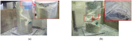
Figure 14.
Compressive fracture types in the hybrid-CFFT. (a) FFRP delamination and (b) strand separation.
The load–displacement and stress–strain relationships obtained from the data measured through the LVDT and strain gauge are shown in Figure 15 and Figure 16, respectively.
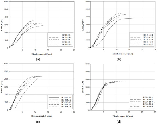
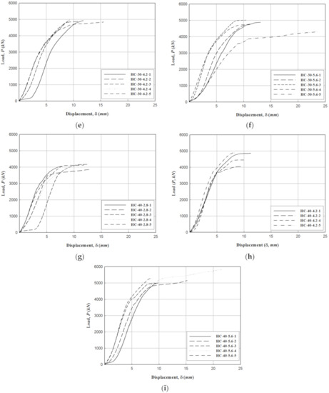
Figure 15.
Load–displacement relationship of the hybrid-CFFT: (a) HC-21-2.8, (b) HC-21-4.2, (c) HC-21-5.6, (d) HC-30-2.8, (e) HC-30-4.2, (f) HC-30-5.6, (g) HC-40-2.8, (h) HC-40-4.2, and (i) HC-40-5.6.
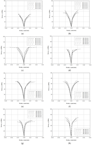
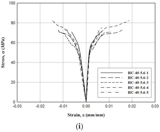
Figure 16.
Stress–strain relationship of the hybrid−CFFT: (a) HC−21−2.8, (b) HC−21−4.2, (c) HC−21−5.6, (d) HC−30−2.8, (e) HC−30−4.2, (f) HC−30−5.6, (g) HC−40−2.8, (h) HC−40−4.2, and (i) HC−40−5.6.
4. Analysis of Experimental Results
Test results of the hybrid-CFFT showed that the compressive strength increased as the compressive pressure increased according to the FFRP thickness and standard design strength of concrete, while the increase range was lower when the compressive pressure exceeded 3.5 MPa and the standard design strength of concrete exceeded 30 MPa. Figure 17 and Figure 18 show the average compressive strength of CFFT according to the standard design strength of concrete and the confining pressure of the hybrid-CFFT specimen.
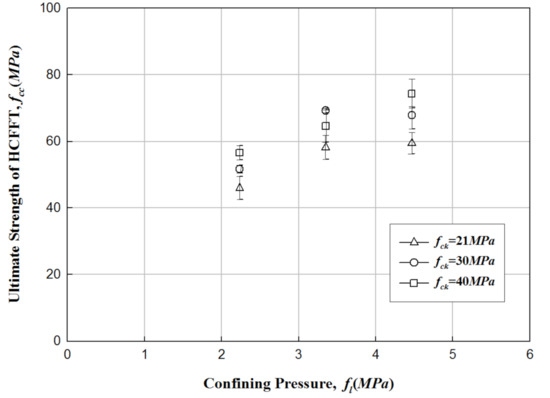
Figure 17.
Average compressive strength of hybrid−CFFT with respect to the increase in the confinement ratio.
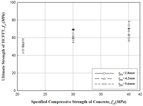
Figure 18.
Average compressive strength of hybrid−CFFT with respect to the increase in the design strength of concrete.
The relationship between the strength ratio and confinement ratio (45 experimental data) of the hybrid−CFFT specimen is plotted in Figure 19. The confinement ratio of the hybrid−CFFT compressed specimen had the same strength ratio as that of the CFT section proposed in the previous study [3,4,5,6,7,8,9]. The experimental data showed a linear distribution from which a regression analysis was performed to obtain the linear relationship. As explained above, the confinement ratio and strength ratio are defined from the slope of this straight line, as expressed in Equation (4).
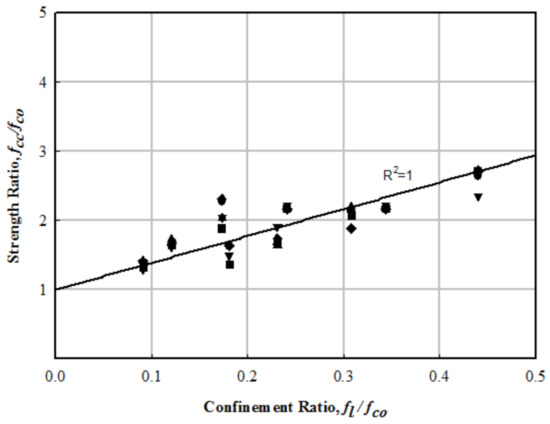
Figure 19.
Relationship between strength ratio and confinement ratio of the hybrid−CFFT.
The compressive strength of the hybrid−CFFT with respect to the rate of increase is computed using Equation (5). The first term represents the compressive strength of the concrete confined by the FFRP, while the second term is that of PFRP. The displacements of confined concrete and PFRP are identical, and the increase in compressive strength is 10.3% of the PFRP compressive strength with respect to the parallel relationship that is distributed to be applied [21].
Here, PHybrid-CFFT is the maximum compressive load of the hybrid−CFFT, ACo is the cross-sectional area of the confined concrete, fp is the fracture stress of PFRP, and Apfrp is the cross-sectional area of PFRP.
5. Finite Element Analysis
To compare the results of compressive strength testing of the hybrid−CFFT, ANSYS workbench [25], which is a universal finite element analysis (FEA) software, was used to perform the structural analysis. FEA was performed by reflecting the size of the experimental member, standard design strength of concrete, and FRP thickness. The mechanical properties of the hybrid-CFFT obtained from a previous study [26] were applied, which are shown in Table 10. For the boundary conditions, all the lower surfaces of the analysis model were fixed. For the load, the maximum load obtained by the experiment was applied by placing a loading plate on the top of the analysis model similar to the experimental conditions. Furthermore, the analytical results were examined for the central part, which is the farthest from the loading point and the boundary conditions. Figure 20 shows the FEA model for the hybrid-CFFT. The overall stress distributions of the hybrid-CFFT specimens are shown in Figure 21, while the stress distributions at the central part are shown in Figure 22 [27]. Table 11 and Figure 23 summarize the comparison of the results of compressive strength testing of hybrid-CFFT via experiments, FEA, and the compressive strength equation according to each variable. When compared to the experimental results, the FEA and the compressive strength equation results were found to have 0.13–17.96% and −5.97–15.44% errors, respectively. Dividing the load obtained using the maximum load estimation equation (Equation (5)) by the cross-sectional area showed a linear behavior of the compressive strength according to the thickness of FFRP; the linearity was consistent with the FEA and experimental results. This observation is considered to be due to the use of a simple design equation in the regression analysis. The design equation and FEA obtained errors that indicate the applicability of the design, and the errors were confirmed to be within a safe range, compared with the experimental value.
Table 10.
Mechanical properties of the hybrid−CFFT.
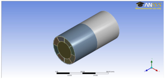
Figure 20.
Finite element analysis (FEA) model for compressive behavior of the hybrid−CFFT.
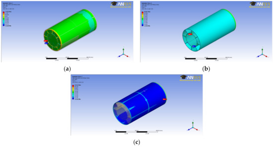
Figure 21.
FEA of the hybrid−CFFT: (a) Concrete, (b) PFRP, and (c) FFRP.
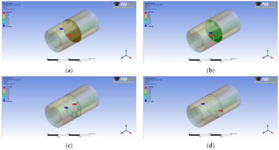
Figure 22.
FEA of the center of the hybrid−CFFT: (a) overall, (b) concrete, (c) PFRP, and (d) FFRP.
Table 11.
Comparative results of the hybrid−CFFT.
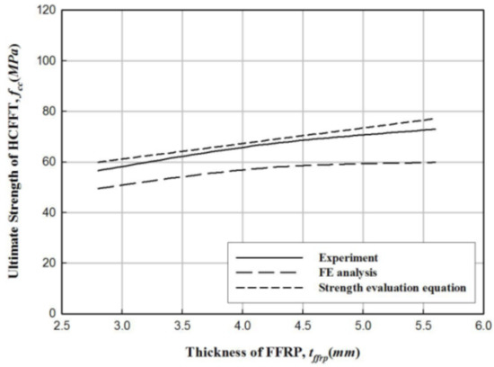
Figure 23.
Hybrid−CFFT analysis results comparison (fco = 40 MPa).
6. Strength Comparison of Hybrid−CFFT, CFT, and PHC Piles
The reason for the comparison of the compressive performance of the hybrid−CFFT with other members (Table 12) is to ensure its possible use as a structural member.
Table 12.
Compressive strength comparison of hybrid−CFFT, CFT, and PHC piles.
Based on previous studies on the structural performance of the concrete-filled tube (CFT) and pre-tensioned spun high strength concrete (PHC) piles widely used in Korea, the compressive strength of the piles with similar member sizes and design strength of concrete to the hybrid−CFFT was compared [28,29]. As shown in Table 12, the hybrid-CFFT pile exhibited 14.32% and 3.8% better compressive strength than those of the CFT and PHC piles, respectively.
7. Conclusions
In this study, we comparatively analyzed the compressive strength of the hybrid-CFFT to evaluate its load-bearing performance. The compressive strength testing results of PFRP-FFRP indicated that the compression performance improved as the thickness of FFRP increased. Further, the confining pressure increased as the thickness of FFRP increased within the experimental section of the hybrid−CFFT. The compressive strength increased with an increase in the confining pressure and the standard design strength of concrete. When the confining pressure was 3.5 MPa, the strength decreased when the concrete standard design strength was 30 MPa or more. In addition, a greater increase in strength was observed when the confining pressure was increased, rather than the strength of concrete. Results of the experiment indicate that the thickness of FFRP decreases over a definite dimension. The compressive strength of the hybrid−CFFT is determined by the confining pressure according to the thickness of the FFRP and the design strength of the concrete. The core concrete is more responsible for delivering the load than for increasing the compressive strength of the member, which is more affected by the thickness of the FFRP than the design strength of concrete. In terms of the fracture of the hybrid-CFFT, the strength does not decrease even when the inner concrete is fractured, and, thus, the slope of the stress–strain curve is reduced, and the material can continuously resist the load until the FRP is fractured.
Author Contributions
Conceptualization, S.-H.K.; formal analysis, S.-H.K.; resources, I.-K.K.; data curation, S.-H.K. and I.-K.K.; writing—original draft preparation, I.-K.K. and S.-H.K.; writing—review and editing, S.-H.K.; project administration, I.-K.K. All authors have read and agreed to the published version of the manuscript.
Funding
This research received no external funding.
Institutional Review Board Statement
Not applicable.
Informed Consent Statement
Informed consent was obtained from all subjects involved in the study.
Data Availability Statement
Data sharing is not applicable to this article.
Acknowledgments
This study was supported by the Construction Technology Innovation Program (CTIP) of the Korea Institute of Construction & Technology Evaluation and Planning (KICTEP). (No. 10CCTI-C053530-02-000000).
Conflicts of Interest
The authors declare no conflict of interest.
References
- Lampo, R.; Noskèr, T.; Barno, D.; Busel, J.; Maher, A.; Dutta, P.; Odello, R. Development and Demonstration of FRP Composite Fender. Loadbearing and Sheet Piling System; Technical Report; Construction Engineering Research Lab. (Army): Champaign IL, USA, 1998. [Google Scholar]
- The Federal Highway Administration (FHWA). A Laboratory and Field Study of Composite Piles for Bridge Substractures; Report No. FHWA-HRT-04-043; The Federal Highway Administration: Washington, DC, USA, 2006. [Google Scholar]
- Kim, H.T.; Lee, M.J.; Park, J.W.; Yoon, S.J.; Han, Y.J. Verification of Applicability of Hybrid CFFT Pile for Numerical Analysis. J. Korean Geo-Environ. Soc. 2011, 12, 59–67. [Google Scholar]
- Richart, F.E.; Brandtzaeg, A.; Brown, R.L. The Failure of Plain and Spiral Reinforced Concrete in Compression; Engineering Experiment Station Bullentin, 190; University of Illinois: Urban, IL, USA, 1929. [Google Scholar]
- Morales, S.M. Spirally-Reinforced High Strength Concrete Columns; Report No. 82-10; Cornell University: Ithaca, NY, USA, 1982. [Google Scholar]
- Lyenger, K.T.; Mie, M.; Nagi Reddy, K. Stress-Strain Characteristics of Concrete Confined in Steel Binders. Mag. Concr. Res. 1970, 22, 173–184. [Google Scholar]
- Wei, Y.; Jiang, C.; Wu, Y.-F. Confinement effectiveness of circular concrete-filled steel tubular columns under axial compression. J. Constr. Steel Res. 2019, 158, 15–27. [Google Scholar] [CrossRef]
- Nanni, A.; Bradford, N.M. FRP jacketed concrete under uniaxial compression. Constr. Build. Mater. 1995, 9, 115–124. [Google Scholar] [CrossRef]
- Toutanji, H. Stress-Strain Relationship of Concrete Cylinders Confined with FRP Composites. ACI Mater. J. 1999, 96, 397–404. [Google Scholar]
- Picher, F.; Rochette, P.; Labossiere, P. Confinement of Concrete Cylinders with CFRP. In Proceedings of the first International Conference on Composites in Infrastructure, Tuscon, AZ, USA, 15–17 January 1996; pp. 829–841. [Google Scholar]
- Chan, C.-M.; Grierson, D.E.; Sherbourne, A.N. Automatic Optimal Design of Tall Steel Building Frameworks. J. Struct. Eng. 1995, 121, 838–847. [Google Scholar] [CrossRef]
- Zhu, Z.; Ahmad, I.; Mirmiran, A. Effect of Column Parameters on Axial Compression Behavior of Concrete-Filled FRP Tubes. Adv. Struct. Eng. 2005, 8, 443–449. [Google Scholar] [CrossRef]
- Tian, H.; Zhou, Z.; Wei, Y.; Wang, Y.; Lu, J. Experimental investigation on axial compressive behavior of ultra-high performance concrete (UHPC) filled glass FRP tubes. Constr. Build. Mater. 2019, 225, 678–691. [Google Scholar] [CrossRef]
- Gao, C.; Huang, L.; Yan, L.; Ma, G.; Xu, L. Compressive behavior of CFFT with inner steel wire mesh. Compos. Struct. 2015, 133, 322–330. [Google Scholar] [CrossRef]
- Richart, F.E.; Brandtzaeg, A.; Brown, R.L. A Study of the Failure of Concrete under Combined Compressive Stresses; Engineering Experiment Station Bull, 185; University of Illinois: Urbana, IL, USA, 1928. [Google Scholar]
- Karbhari, V.M.; Gao, Y. Composite Jacketed Concrete under Uniaxial Compression—Verification of Simple Design Equations. J. Mater. Civ. Eng. 1997, 9, 185–193. [Google Scholar] [CrossRef]
- Samaan, M. Analytical and Experimental Investigation of FRP Concrete Composite Columns. Ph.D. Thesis, University of Central Florida, Orlando, FL, USA, 1998. [Google Scholar]
- Miyauchi, K.; Inoue, S.; Kuroda, T.; Kobayashi, A. Strengthening Effects of Concrete Columns with Carbon Fiber Sheet. Trans. Jpn. Concr. Inst. 1999, 21, 143–150. [Google Scholar]
- Saafi, M.; Toutanji, H.; Li, Z. Behavior of Concrete Columns Confined with Fiber Reinforced Polymer Tubes. ACI Mater. J. 1999, 96, 500–509. [Google Scholar]
- Lam, J.G.; Teng, L. Design-Oriented Stress-Strain Model for FRP-Confined Concrete. Constr. Build. Mater. 2003, 17, 471–489. [Google Scholar] [CrossRef]
- An, D.J. Structural Characteristics of Hybrid FRP-Concrete Composite Pile. Ph.D. Thesis, Hongik University, Seoul, Korea, 2011. [Google Scholar]
- ASTM D3039/3039M. Standard Test Method for Tensile Properties of Polymer Matrix Composite Materials; ASTM International D3039/3039M-17; ASTM International: West Conshohochen, PA, USA, 2017. [Google Scholar]
- ASTM D2290. Standard Test Method for Apparent Hoop Tensile Strength of Plastic or Reinforced Plastic Pipe; ASTM International D2290-19a; ASTM International: West Conshohochen, PA, USA, 2019. [Google Scholar]
- KS F 2405. Standard Test Method for Compressive Strength of Concrete; Korean Standards Association: Seoul, Korea, 2017. [Google Scholar]
- ANSYS. Release 11.0 Documentation for ANSYS; ANSYS: Canonsburg, PA, USA, 2008. [Google Scholar]
- Choi, J.-W.; Park, J.-S.; Nam, J.-H.; An, D.-J.; Kang, I.-K.; Yoon, S.-J. An Experimental Study for the Compression Strength of Hybrid CFFT Pile. J. Korean Soc. Adv. Compos. Struct. 2011, 2, 30–39. [Google Scholar] [CrossRef]
- Lee, Y.-G.; Choi, J.-W.; Park, J.-S.; Yoon, S.-J. Compression Strength Test of FRP Reinforced Concrete Composite Pile. J. Korean Soc. Adv. Compos. Struct. 2011, 2, 19–27. [Google Scholar] [CrossRef][Green Version]
- Choi, Y.; Kim, D.C.; Kim, S.S.; Nam, M.S. Development and Test Construction Plan of a Noise & Vibration-Free PHC Screw Pile. In Proceedings of the 2009 Workshop of Korea Geotechnical Society of Foundation Technical Committee, Seoul, Korea, 25 June 2009; pp. 18–33. [Google Scholar]
- Jung, S.-K.; Kim, S.-H.; Choi, S.-M.; Won, Y.-A.; Kim, H.Y. Evaluation of the Residual Strength of Square CFT Columns After a Fire Through Structural Performance Evaluation Test. In Urban Habitat Constructions under Catastrophic Events, Proceedings of the Final Conference, Naples, Italy, 16–18 September 2010; Mazzolani, Ed.; Taylor & Francis Group: London, UK, 2010; pp. 283–288. [Google Scholar]


Publisher’s Note: MDPI stays neutral with regard to jurisdictional claims in published maps and institutional affiliations. |
© 2021 by the authors. Licensee MDPI, Basel, Switzerland. This article is an open access article distributed under the terms and conditions of the Creative Commons Attribution (CC BY) license (http://creativecommons.org/licenses/by/4.0/).