Review

Conventional Selection of Mechanical Fasteners for Flat Belts

1
Calisia University, Nowy Świat 4, 62-800 Kalisz, Poland
2
Institute of Machine Design, Poznan University of Technology, Piotrowo 3, 60-965 Poznań, Poland
3
Faculty of Mechatronics, Kazimierz Wielki University, Chodkiewicza 30, 85-062 Bydgoszcz, Poland
*
Author to whom correspondence should be addressed.
Appl. Sci. 2021, 11(7), 2916; https://doi.org/10.3390/app11072916
Submission received: 23 February 2021 / Revised: 17 March 2021 / Accepted: 18 March 2021 / Published: 24 March 2021
(This article belongs to the Section Mechanical Engineering)

Abstract

:
Due to the variety of materials used for flat belts of belt conveyors and the further development of material engineering in relation to these belts, the methods of their connection become an increasingly problematic issue. The belts can be connected mainly in three ways: vulcanized (weldable or heat-weldable), glued or mechanically. The latter method is one of the simplest and most universal in terms of the material variety of belts; however, there are many design variations of mechanical fasteners, and each of them has a certain advantage in a narrow group of properties, e.g., the thickness spectrum of a conveyor belt, the minimum diameter of a drive roller or the range of transferable longitudinal loads. The objective of this paper is to analyze the design solutions of commercial mechanical fasteners used mainly for flat rubber-fabric, composite or plastic belts. To fulfill this goal, a preliminary analysis of the stress distribution for an exemplary solid mechanical fastener was carried out in two cases: during ramp-up and during circulating around the roll, followed by a detailed review of commercial solutions available on the market. In addition to determining the current state of knowledge and technology and determining the state of ignorance, special algorithm and design maps have been created, thanks to which the process of selecting the right mechanical fastening will be easier. The overview includes several tables with detailed information on individual connection properties. Additionally, several design aspects were derived, within which individual mechanical connections may differ. This is to enable the generation of customized solutions in the future by proposing an appropriate mathematical model, on the basis of which it will be possible to generate optimal design properties for a given application.

1. Introduction

The rapid increase in production, which characterizes the development of modern industry, requires systematic improvement on the level of organization and mechanization of production processes. This also applies to the state of organization and the development of in-plant systems and means of transport, which must ensure the continuous circulation of raw materials, semi-finished products and finished products by all production, control and storage stocks, as well as guarantee an uninterrupted production process of auxiliary materials [1].
There are two basic systems of internal transport solutions: intermittent transport and continuous transport. The first one is carried out by palletization and concretization, and it is moved with the help of mechanized equipment operated by an operator. The latter, in turn, concerns materials that are continuously moved without the operator’s participation. Continuous transport includes, among others, conveyors.
Conveyors can be categorized, among other things, on the basis of the element transporting the transported material, the design, and operational features. In addition to beltless conveyors and conveyors with an intermediate medium, it is important to distinguish belt conveyors, which move the transported material using a belt, the main driving element of the conveyor. In addition to belt conveyors, there are also member conveyors, bucket conveyors, claw conveyors and pull-carrying conveyors. It should be mentioned here that, in general, belt conveyors are part of the group of devices using a belt drive, whose main feature is the transmission of torque over long distances. Belts are used because they are light and prevent the drive from emitting excessive noise [2]. Belt conveyors are also suitable for building modular systems of belt conveyors, which can be used in a transport automation system [3]. Belt conveyor transportation systems are also considered to be the most effective for handling large volumes of bulk material [4]. The disadvantages include the occurrence of transverse vibrations of the conveyor belts. These vibrations are caused by the eccentricity of the rollers, which results from production errors or from sticking of the transported material to the support rollers of the lower branch of the conveyor [5]. The properties of the conveyor belt itself are also very dependent on thermal and humidity conditions [6].
In the general design of belt conveyors, one can primarily distinguish a drive roller, a tension roller, a belt, carry idlers and return idlers [7]. The drive roller is coupled to the shaft of the motor or geared motor and transmits the torque to the belt system. The tension roller acts as a reversing roller, thanks to which the conveyor belt returns, and as a tensioning function, it is usually mounted on a movable guide that moves linearly thanks to the screw mechanism. In such a system, the conveyor belt forms a closed system, and therefore it is necessary to connect the conveyor belts. The above-mentioned structural elements are shown in Figure 1. There are also other types of structures, such as suspended belt conveyors, in which the conveyor belt is fastened in special brackets. These, in turn, are guided in tubular guides arranged on both sides of the belt along the length of the conveyor. It is, therefore, a hybrid of a traditional belt conveyor and a rail transport [8]. Belt conveyors, or rather tracks of their conveyor belts, can form both straight and curved tracks. There is also the option of curving the track of the conveyor belt through a special turning frame [9].
Among the conveyor belts, there are mainly elastic belts that transfer longitudinal and transverse forces resulting from loading with the transported material and own weight, as well as tensile forces arising during belt tensioning. Tensioning the belt is necessary to create on the surface of the driving roller the tractive force needed to overcome the resistance to movement of the conveyor and move the transported material to the desired level and distance. A rubber-fabric belt consists of several layers of rubber and fabric, i.e., spacers forming the core of the belt and transmitting mainly longitudinal and transverse tensile forces, running and bearing covers and side edges. Spacers can be made of cotton, cellulose fiber, viscose silk, polyamide (generally polyamide fibers are nylon, perlon, stylon, capron), polyester (generally polyester fibers are diolene, dacron, terylene), aromatic polyamide (Aramid, the name comes from ARomatische PolyAMID), or glass fiber—usually made of cross-weave fabrics. Covers, on the other hand, are most often made of rubber materials based on CR, NBR and PVC polymers in flame-retardant tapes, or SBR or NR/BR in flame retardant tapes. In addition to elastic fabric-rubber belts, you can also find belts made of the so-called TPU, i.e., thermoplastic polyurethane, most often reinforced with aramid. Thermoplastic polyurethane is a thermoplastic elastomer, which is characterized above all by extraordinary flexibility while maintaining high abrasion and weather resistance. It is not damaged by various solvents and lubricants. It exhibits good toughness resistance, good shock, vibration and shock damping properties, which are of great importance in the field of conveyors. This material is also suitable for mixing with other polymers, such as ABS or PMMA. Increasingly often, you can also come across new material solutions for elastic bands. This primarily includes composite belts. Such conveyor belts are widely used in industry for transporting products using negative pressure [1,10,11,12,13,14,15]. The material diversity of the elastic belts themselves indicates the resulting problem of fastening belts. Due to the fact that each conveyor belt has different mechanical properties, the method of connecting them is a very important aspect.
Conveyor belts can be connected in three main ways: vulcanized (weldable or heat-weldable), glued or mechanically. The latter are used because of the ease of assembly and the possibility of detaching the ends of the belt, e.g., for cleaning the belt. Mechanical fasteners have different durability, depending on many factors. The reason for the reduction of strength or destruction of the mechanical fastener may be excessive loads, fatigue phenomena of the ends of the joined belts or mechanical elements, abrasive wear of metal elements, corrosion or improper execution of the connection. The strength of mechanical connections of conveyor belts is a complex issue due to the variety of materials (materials and structure of the belt and the metal part of the connection) and the load states in the joints. The aforementioned forces that transmit the elastic bands are related in a specific way to the mechanical connections and their properties, or rather to the load-bearing capacity. The relative strength of the mechanical connection of the belt must be at least 50% of the belt’s nominal breaking strength during transport of spoil. The presented connections are especially suitable for elastic fabric-rubber bands without a core made of steel ropes, but also other ones, such as, for example, made of TPU. The connections are designed to be compatible with the standard widths of the manufactured conveyor belts.
Based on the literature [16,17,18,19,20], an initial analysis of the distribution of stresses propagating in the belt conveyor system was performed (Figure 1). It shows a general scheme of the structure of a belt conveyor with the use of a elastic belt and a mechanical fastener, in which the following can be distinguished: 1—mechanical fastener, 2—drive roller, 3—return idler, 4—elastic belt, and 5—tensioning roller (return roller).
A condition of the operation mode of the conveyor without belt slippage is (1). The µ is the coefficient of friction between the conveyor belt and the roller.
S 1 S 2 = e μ α
From the calculus of vectors, it follows that (2).
P = S 1 S 2
After transforming (2) and inserting it into Formula (1), the following result was obtained.
S 2 = P e μ α 1
The force in the upper bend can be calculated from the dependence (2). The value of the resultant force Q loading the shaft was calculated using the famous cosine law (4).
Q = S 1 2 + S 2 2 + 2 S 1 S 2 cos δ
Figure 2 shows detail B in Figure 1, thanks to which it is possible to calculate the inclination angle θ of the resultant force vector Q, which is needed to decompose this force into a vertical and a horizontal component Qx and Qy.
Two auxiliary parameters x and y were introduced, and the angle θ was calculated using trigonometric functions (5) and (6).
x = S 2 sin δ ;   y = S 2 cos δ
tan θ = x S 1 + y = S 2 sin δ S 1 + S 2 cos δ
θ = tan 1 S 2 sin δ S 1 + S 2 cos δ
The calculation of the resultant force loading the main shaft is important in the context of this work, because, as it will turn out in a moment, the mechanical connection generates additional forces that also load the shaft.
Figure 3 shows detail A from Figure 1. This detail is presented in two specific phases of the conveyor’s work cycle—on the left: at the moment of contact of the contact edge, the mechanical connection with the cylindrical surface of the roller (during the run-up on the roller); on the right: when the face of the mechanical connection is tangent to the cylindrical surface of the roller (while circling the roller). This shows in a simplified way the distribution of stresses resulting from the application of a mechanical connection.
When the joint is pushed onto the roller (at the moment of contact), the mechanical fastener acts with a force S1 on the cylindrical surface of the driving roller. By distributing this force into two components, a radial force FR was obtained, which additionally (apart from the Q force) loads the main shaft, and the tangential force FT. This phase is a kind of impulse/shock impact of the joint against the roller, and it is during this phase that the radial load is the greatest. As the joint circulates around the drive roller, the distribution of forces is similar, except that now the tangential force FT is at its greatest value. Some dependencies can be noticed (7).
F T   =   F L ;   F R   =   F L
Figure 4 also shows detail A from Figure 1, but this time in cross-section. It shows an example of a mechanical joint and the forces acting on it. The connecting element can be, for example, either a screw or a rivet. The previously derived forces that load the joint are: FTR—transverse force, which generates tensile of the core of the link (bolt/rivet, etc.) and bending of the plate of the mechanical joint; and FL—longitudinal force, which generates a shear cross section of the link.
An article was found [21] in the available scientific databases that was helpful in the process of choosing the right mechanical connection of flat conveyor belts; however, the development of their design and the use of more and more complex materials for the belts determine the need for a deeper study of this issue. In the second part of this work, a detailed review of existing commercial mechanical joint solutions was carried out to establish the state of knowledge and technology and the state of ignorance. In the summary, an algorithm and special design maps were generated to facilitate the process of selecting the right connection. Several design aspects were also derived to provide the basis to analyze differences between individual mechanical connections as they have different properties and are suitable for different applications. Each of these aspects will be considered individually in the context of further research in the search for a customized design solution.
One of the key parameters in the selection of a mechanical connection is the minimum roller diameter. However, it is not obvious why this is so important. The argument below shows that it is indirectly related to the forces that arise, but the source is only the geometric values. On the basis of conversations with industrialists, information was obtained suggesting that often, even when the required minimum diameter of the connection roll is used, the belts—e.g., staples—become detached. The two arrangements of the roller with the belt and staple fastener are compared below.
The starting point is the assumption of common and identical output parameters. As a conveyor constructor, I want to check what the model of the roller-belt-connection system looks like using two extremely different roller diameters. In this case, the linear speed of the belt must remain the same in both systems, because we want the load to move at a given speed.
v 1 = v 2 = v
The length of the conveyor was set the same.
L 1 = L 2 = L
The width of the belt also remains the same.
B 1 = B 2 = B
The arrangement of the driving roller and the return roller of the same diameter and the horizontal arrangement were adopted. Therefore, the angle of contact in both systems will be the same and equal to 180 degrees.
α 1 = α 2 = α
Then, the same friction lining was applied to the rollers in both systems and the same belt. Therefore, the friction coefficient will be the same.
μ 1 = μ 2 = μ
Therefore, it was concluded that the force ratio in the upper and lower strand must remain the same in both systems. However, does that mean the forces will be the same? This cannot be clearly stated yet.
S 1 I S 2 I = e μ α ;   S 1 I I S 2 I I = e μ α
consequently
S 1 I S 2 I = S 1 I I S 2 I I
As the two rollers will have different diameters, they will also have different rotational speeds. For a larger roller:
n I = 60,000 · v π · D
For a smaller roller:
n I I = 60,000 · v π · d
In this connection, where
D > d
the following is true
n I < n I I
In the so-called basic method for calculating belt conveyors [1,22,23], the circumferential force on the roller in steady motion is equal to the total motion resistance.
P = W C
Total resistance to motion WC consists of several parts
W C = W G + W S + W D
The main resistances WG are calculated from the formula
W G = μ · L · m k + 2 · m t + m l · g
The parameter m k is the mass of the rotating parts of idlers per one meter of the conveyor length. Due to the fact that in both systems the belt length will be the same and the number of upper and lower idlers will be the same, the weight of the rotating elements will also be the same.
m k I = m k I I = m k
The parameter mt is the weight of the belt per one meter of the conveyor length, which is related to the weight of the belt support covers. Due to the use of the same belt in terms of thickness, width and material, this parameter will be the same in both systems
m t I = m t I I = m t
The parameter m l is the mass of spoil loading one meter of the conveyor belt, which is related to the efficiency and linear speed of the belt. We have the same speed in both systems, and we want to achieve the same efficiency; therefore, this parameter also remains the same.
m l I = m l I I = m l
The parameter g is the acceleration of gravity; therefore, it was finally found that the main resistances of motion in both systems are the same in terms of their value.
W G I = W G I I = W G
Concentrated resistances WS are determined using the formula below
W S =   C 1 · W G
Concentrated resistances are caused primarily by inertial forces and frictional forces occurring in the area of the loading point. The C factor in this case depends on the length of the conveyor, which is the same in both systems. Therefore, concentrated resistances have the same value.
W S I = W S I I = W S
Additional resistances WD are caused by the use of a special device in the conveyor (e.g., scraper, rollers ahead, etc.). Therefore, it can also be assumed that in both systems these resistances have the same value.
Ultimately, therefore, it can be concluded that the total resistance to movement in both systems, despite the use of a different roll diameter, are the same in terms of value.
W C I = W C I I = W C
Consequently, the circumferential force in both systems remains the same, and thus the forces in the tendons are also the same.
P I = W C ;   P I I = W C
and so
P I = P I I = P
in that case
S 2 I = P e μ α 1 ;   S 2 I I = P e μ α 1
and so
S 2 I = S 2 I I = S 2
and
S 1 I = S 1 I I = S 1
In connection with the above argumentation, the question arises: why is a minimum diameter of a roller required, if the forces in the tendon remain the same? The answer is shown in Figure 5. Due to the use of a smaller roller, the opening angle between the two hinge plates is greater. As a consequence, the vector of the perpendicular force acting on the plate is larger. Therefore, the essence is only the geometry.
Based on a diligent review of the literature, both academic, didactic and research-oriented, contained in the various available scientific databases, no activities have been found to date that study the presented mechanical connections. These issues are dealt with by producers; however, the results of their research activities are secret and not available for inspection. Therefore, the subject matter discussed in this article represents an area of ignorance, and this work is to fill the empty space in this field.
The above preliminary analysis of the stress distribution in the exemplary connection was performed. Of course, this distribution will be presented in further detail in the research process of connections, also with the use of systems operating with the finite element method. There will also be more variants of the distribution of forces, as each connection is characterized by a different structure. A mathematical proof was also drawn because of the necessity of taking into account the minimum diameter of the roller, which is one of the three key parameters when choosing the right joint. A cross-sectional overview of most of the possible alternatives in flat belt connection is provided below. Mainly—for the sake of this work—in the context of creating an algorithm and special design maps to assist in choosing the right joining, but also—for future work—in relation to the various design aspects listed in the summary. This was to lay the groundwork for future detailed research. It is expected that the final stage of activities in the field of this topic will be the development of a mathematical model that will allow to design an optimal mechanical connection for the given output parameters in terms of construction.

2. Solution Overview

Existing commercial mechanical connection solutions are presented in this section. Several similar solutions have been implemented by several suppliers simultaneously. If such a situation applies to a given mechanical connection, the paper presents only one proposal from the leading manufacturer. The review is based on catalogs, brochures and information from manufacturers’ websites [24,25,26]. Each time, the most important properties of the connection are presented here in tabular form, such as the thickness of the belts to be used, the minimum diameter of the drive roller, mechanical strength (ability to transmit longitudinal loads), operating temperature spectrum, types of resistance, connection material, material of the belts used, and many more. Then the installation method and the general construction of the fastener are briefly described. Each fastener is also presented graphically.

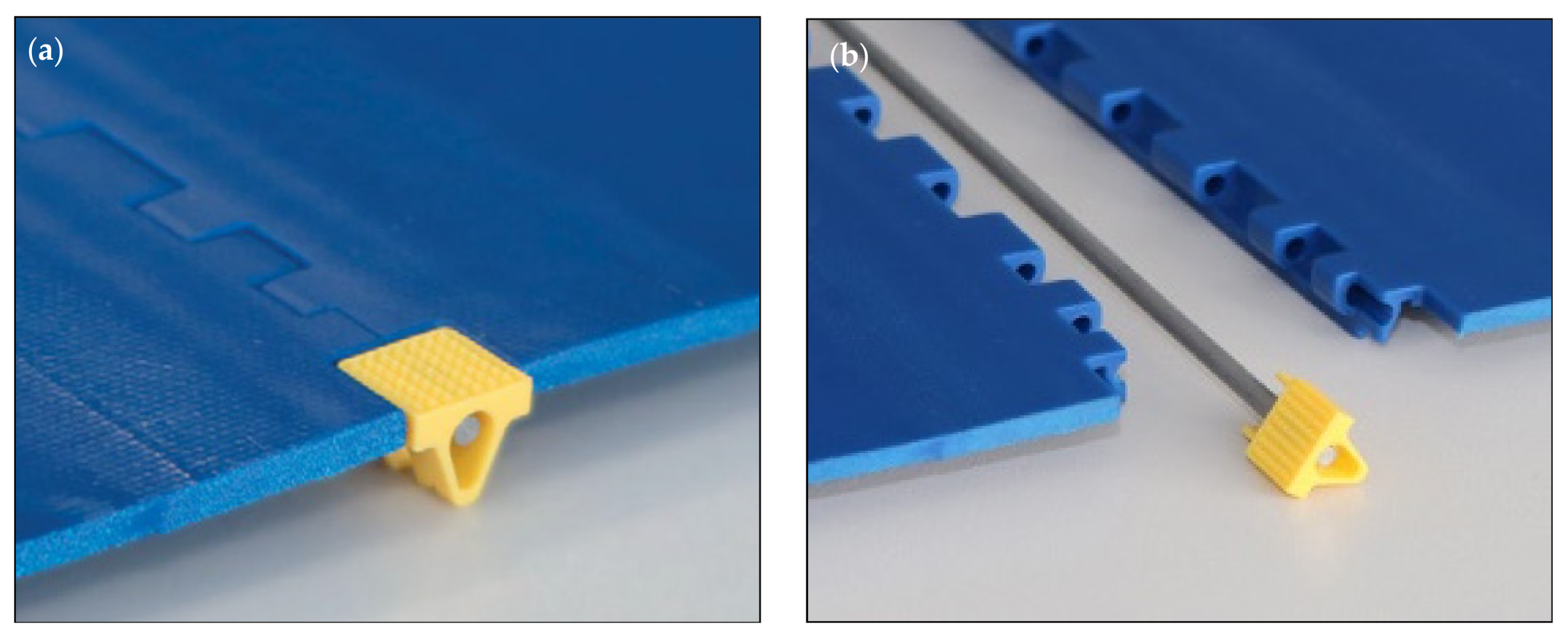
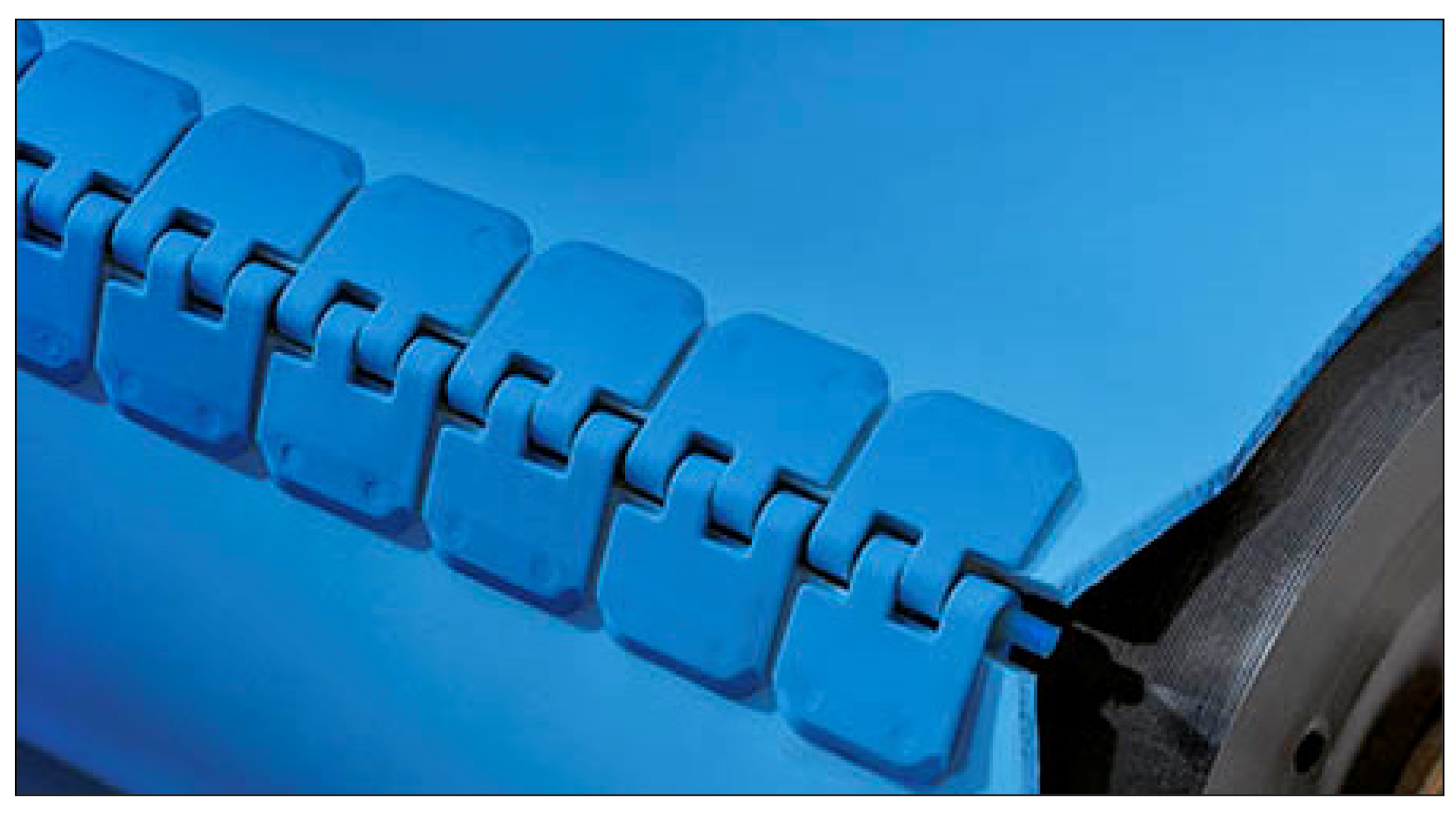
2.1. Hinge Fastener with a Patch Welded to a Monolithic Belt

Many manufacturers offer monolithic conveyor belts made entirely of one material—flexible plastic. In this variant, special mechanical lace with patches is used. These patches—made of identical material to the material of the conveyor belt—are welded together with the belt. An example of such a connection is shown in Figure 6. Mechanical lace is a fastener in the form of patches with holes through which the hinge pin passes. By removing this pin, the connection can be easily detached. The pin can be plastic or metal. The patches are made of the same material as the belt—aramid-reinforced thermoplastic polyurethane (TPU). There is no combination of elements in this type that penetrate the belt material, which would weaken the belt structure. The solution is not very universal, and it is difficult to compare it with other solutions due to the possibility of application only in the monolithic series belts. A special series heat press with control unit is required for installation. It does not need water for cooling and there are no exposed hot parts. The size of the press depends on the width of the belt. Joining cycle of the heat press make the thermoplastic joining is performed automatically. The manufacturer ensures that the weld itself is stronger than the hinge mechanical joint. In the context of future research related to the optimal design features for mechanical connections of flat belts, the hybrid method of connection deserves attention. There are no elements penetrating the belt material, and the joint itself is applied by welding. Of course, this is only possible due to the specificity of TPU. However, the problem may be the difficulty of removing the hinge pin and—as the manufacturer himself points out—the possibility of dirt accumulating in the connection holes. It is anticipated that when a plastic hinge pin is used, the first element that will fail will be that pin (unless the material of the pin is stronger than that of the fastener).
There is one more solution—the same, but with a special stick. An example is shown in Figure 7. This solution—just like the previous one—is a fastener in the form of patches with holes through which the hinge pin passes. The difference is that this has special sticks with a non-slip surface. These sticks are coupled with hinge pins and make it easy to detach the tapes. Disconnecting is so simple that when using the fastener, the belt can be cleaned after it is removed from the conveyor. The stick is made of monolithically small dowel pins that go into the holes in the fitting. In this way, the spontaneous disconnection of the mechanical connection is ensured. The construction is also—compared to the Mechanical Lace—more compact, so there is no risk of dirt getting into the connection holes. This effect was achieved by reducing the clearances to a minimum between individual connection elements. A special heat press is also required for installation. In the context of future research, the hybrid connection system used here will also be considered. Summarizing both proposals briefly, in the future the authors will try to extend the applicability of such a hybrid combination also to other belts, not only those from the CleandriveTM series. The problem—also in the case of Mechanical Lace—is the shape of the corner that creates the fastener. This will have a negative impact on belt deflection during operation, as pulleys are not compatible with this connection. This also generates another problem—the impossibility of using a relatively small diameter pulley (compared to other solutions for mechanical joining of flat belts, which are presented later in this work).

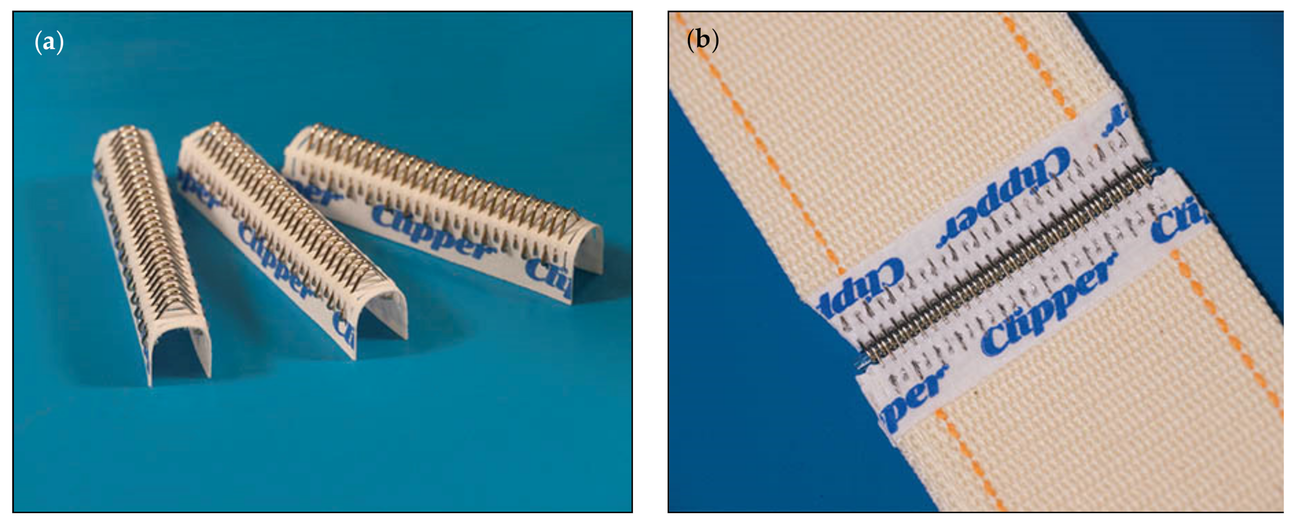
2.2. Hinge Plate Fastener with Staples Attachment Method

An example is shown in Figure 8. Intended for joining light and medium-duty synthetic carcass belting. The applications that this fastener can be used in include package and parts conveying, food and sanitary contact, agricultural harvesting and handling, recycling and scrap handling, and wood products. The fastener in this case is a bent plate in which the hinge pin is finally mounted. Two large and thick staples are also pre-embedded here. Single fasteners are available as continuous strips consisting of several fasteners. Extended plate design separates the point of fastener penetration from the line of belt flexing to eliminate splice fatigue at the point of belt attachment. Table 1, below, shows what the fasteners are resistant to, depending on the material made.
Hinge pins made of various materials and designed for different applications—Table 2.
Staples are hammer driven through the fastener and belt, working between the carcass fibers without severing them. The staples are then clinched cross-wise to the belt, so that belt tension does not pull against the staples to unclinch them. This is how the fastener is installed manually. Special installation tools are needed. For even better mounting, a system with a pneumatic rammer can be used. To ensure a low-profile connection—compatible with the thickness of the belt—unfortunately, the belt needs to be pre-cut so that the chamfered connection plates can be flush with the belt surface.
Another design solution is the connection shown in Figure 9. Made of high-tensile plated carbon steel (HLE). This connection is distinguished in the study due to the arrangement of staples—in this design variant, the staples are pre-applied in the holes arranged in a V-shape. The geometric aspect is interesting from a research point of view (with respect to the influence of the arrangement on the stress distribution inside the belt during the conveyor operation).
The above two solutions are plate connections, i.e., those in which the hinge elements are in the form of bent plates.
There is also a variation in which, instead of tiles, there are bent wires with flats at the ends. There are gaps in these flats for the staples to pass through. See example in Figure 10. Hinge pins are available in most materials and lagging, as in the previous designs from the same manufacturer. However, for the reinforced series, there are special pins with increased diameter. Their use increases the life of the connection by up to 33%.

2.3. Hinge Fastener with Rivets Attachment Method

An example is shown in Figure 11. For belts made of PVC, used for food and sanitary contact, and in the electronics industry. The system of fastening, which is made of plastic plates, is also joined with plastic rivets. Available in three different plastic materials—Table 3.
To install the above-mentioned fastener, you need a special portable device. The rivets are spin set through heat and friction to provide a long-lasting splice.
Another example, this time with metal plates and rivets, is shown in Figure 12. Intended for abusive round hay baling and underground mining. It is a fastener composed of stainless-steel plates with rivets. The assembly uses a handheld device called a portable hand applicator tool kit or a special multiple rivet device installation tool kit with pneumatic mounting.
Finally, the strongest of these types of connections is shown in Figure 13. The solution is similar to the previous one, not only in terms of construction (rivets, plates, chamfered), but also in terms of the method of installation and the tools used. This is the most durable combination of all, for really heavy industry: cement, underground and surface mining, crushed stone, coal and hard rock, salt, wood processing, asphalt plants. Table 4 below shows what the fasteners are resistant to, depending on the material made.
Hinge pins can be made of various materials. Details are presented in Table 5, where the middle column shows the application for a given hinge pin.

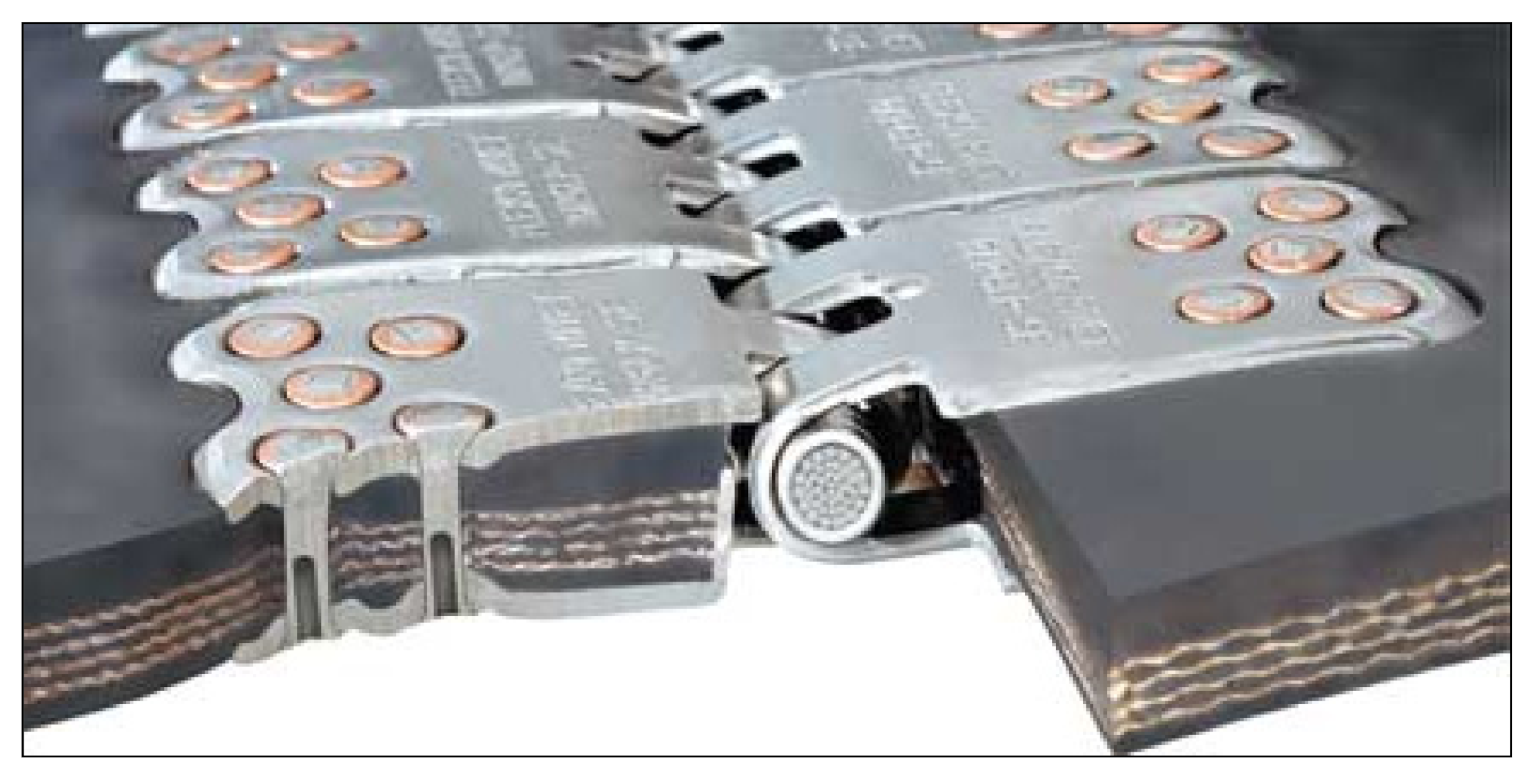
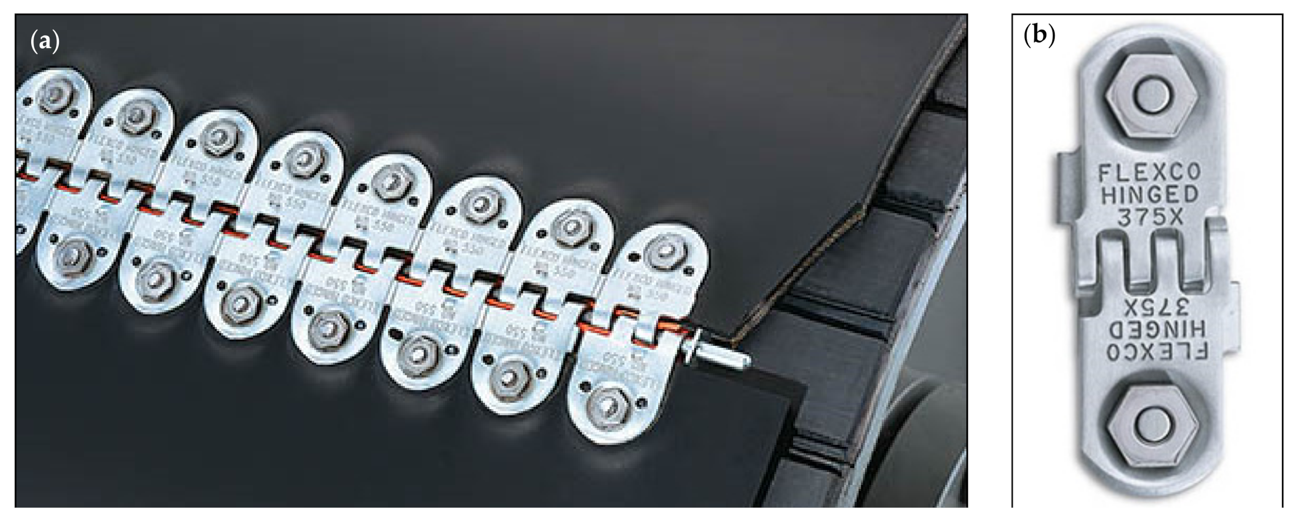
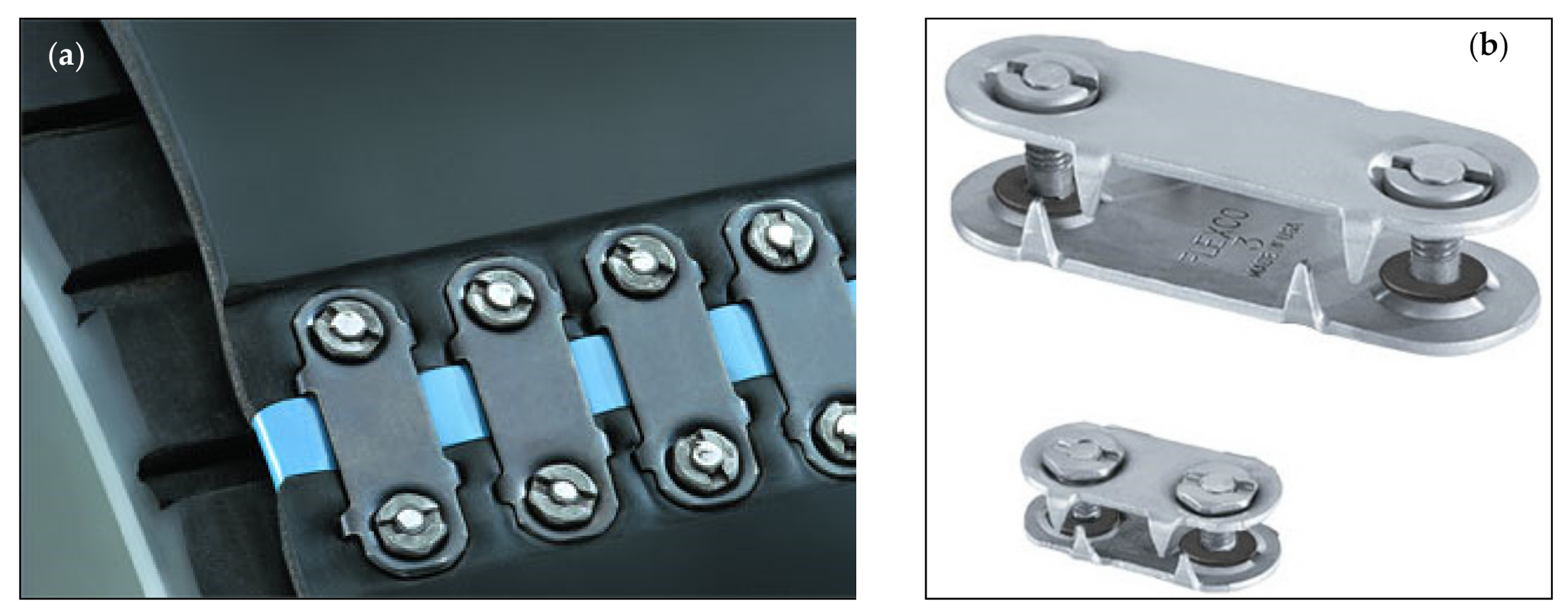
2.4. Fastener with Bolts/Screws Attachment Method

An example is shown in Figure 14. For construction and road equipment, coal, salt, potash, grain, wood products, recycling applications. Hinge pins can be made of various materials and designed for different applications. Details are presented in Table 6.
Table 7, below, shows what the fasteners are resistant to, depending on the material made.
A special plastic filler tubing (Figure 14a—orange tube) is also used for the connection and keeps sifting of fine materials through the hinged joint to a minimum.

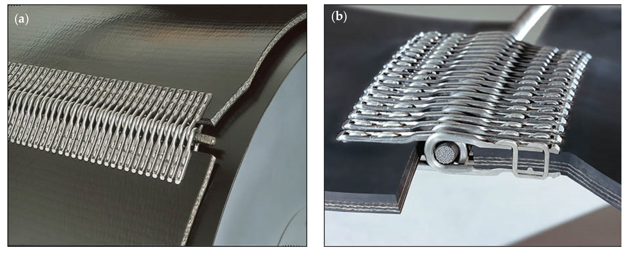
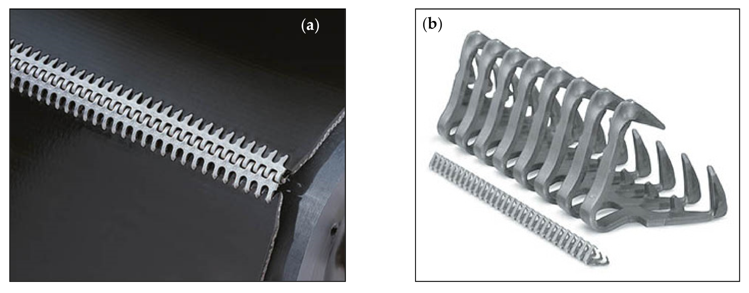
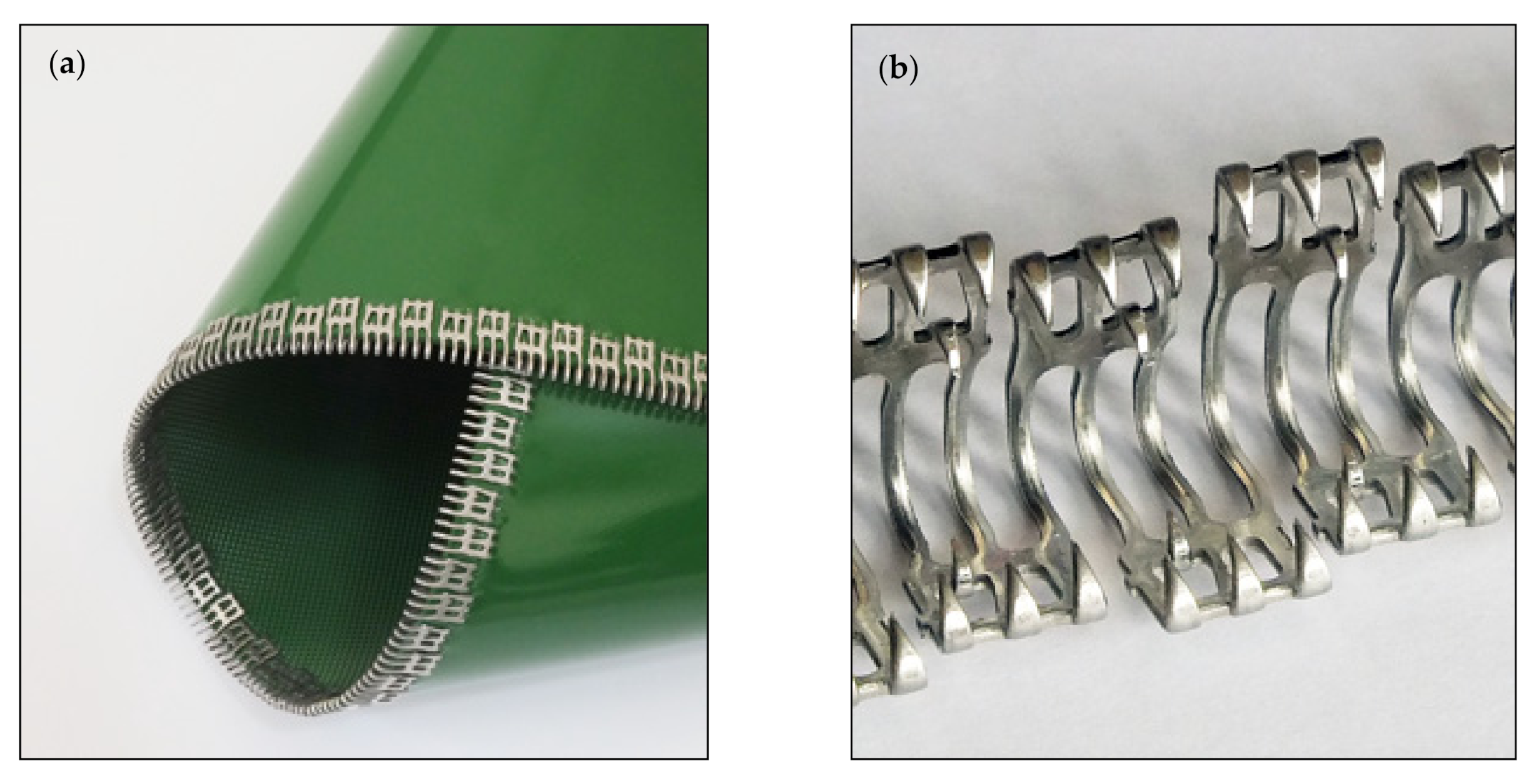
2.5. Wire Hook Fastener

An example of such a connection is shown in Figure 15. For belts made of solid woven PVC and can be applied in package and parts handling, general manufacturing, commercial laundry, food processing, agriculture, filter media. Table 8 shows what the fasteners are resistant to, depending on the material made.
It is a hook system using different wire diameters and leg lengths. Available with two types of hooks: welded to a common rod (Figure 15a) to increase installation safety and facilitate interlocking of the ends of the straps—and carded fasteners—and single hooks secured on carding paper (Figure 15b) for safe handling. Hinge pins are available in different variants, as shown in Table 9. Installation requires a special tool, which gently and precisely rolls the hooks around the belt.
A smaller variation of such a solution with corrugated Perlon hinge pin—mainly for the laundry industry—is shown in Figure 16. For PVC, PU, cotton and cotton mix tape, and filter belts. This is a double fastening system: by hooks and by adhesive bonding. The individual fasteners are secured in the material of a special patch. During quick assembly, the adhesive is activated by heated jaws. The attachment points are covered with a patch during assembly to prevent hooks from becoming snagged and damage to the belt material. The hooks are integrated into the polyester patch material. The hinge pin that connects both ends of the belt is made of a so-called Perlon. It is anti-corrosive and provides lubrication of the lap joint. Mounting is performed by hand or using a hydraulic mounting tool.

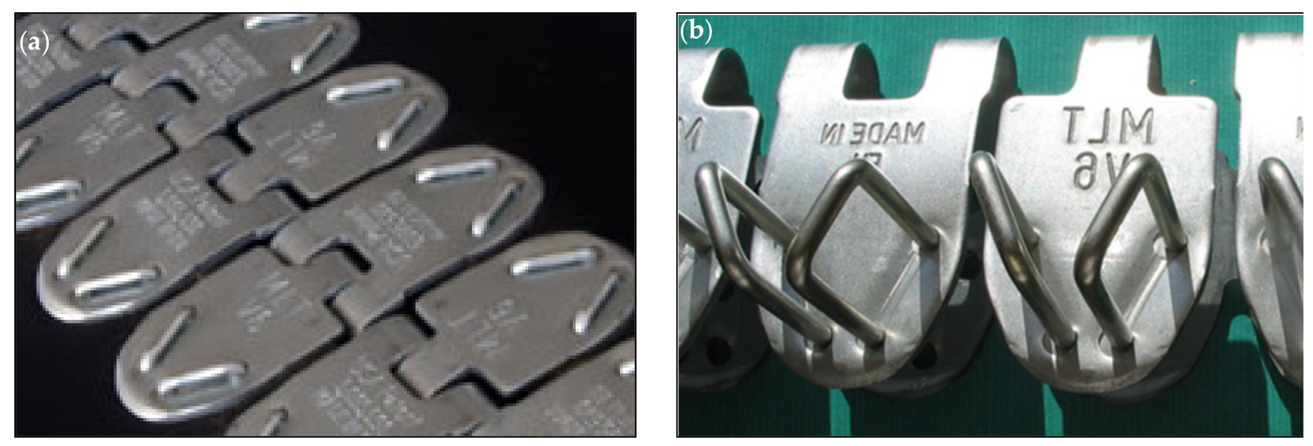
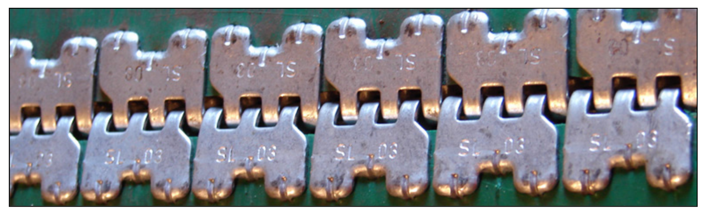
2.6. Metal Fastener with Legs or Clamp

A first example is shown in Figure 17. For PVC, PU and PES belts. Application: food manufacturing, filter media, package and parts handling. It is a system with an alternating leg structure with four different leg lengths. It ensures constant compression, and as a result, a flat and uniform connection. The finished lacing is very durable. Made of AISI 316 stainless steel. The flat, continuous top bar design eliminates belt ripple and reduces the risk of fasteners falling out. There is also a double lacing pattern which provides good holding strength without compromising the integrity of the belt structure. Assembly, as in the case of the previous type of fastening, is also performed using a special installation tool.
Another example is shown in Figure 18. This is for rubber-fabric belting. Application: agricultural harvesting and handling, package and parts conveying, food and sanitary contact, recycling and scrap handling, wood products.
The example in Figure 19 is an even more clever and sophisticated solution. It has double rows of teeth, which has a positive effect on durability. Suitable for work in a trough arrangement. Made of non-magnetic 316L stainless steel. Application for light belts with a thickness of 1 mm to 5 mm. The minimum diameter of the pulley is from 20 mm to 75 mm (depending on the size of the mechanical fastener). A special multitool can be used for installation. The teeth are arranged in a meander pattern. This meander design eliminates risk of losing claws.
Another design solution is the example shown in Figure 20. Clamping system that only requires a hard surface and a hammer. The upper part of the fastener has special hooks which, during assembly, stop on the lower part of the coupler, catching on convex bridges.

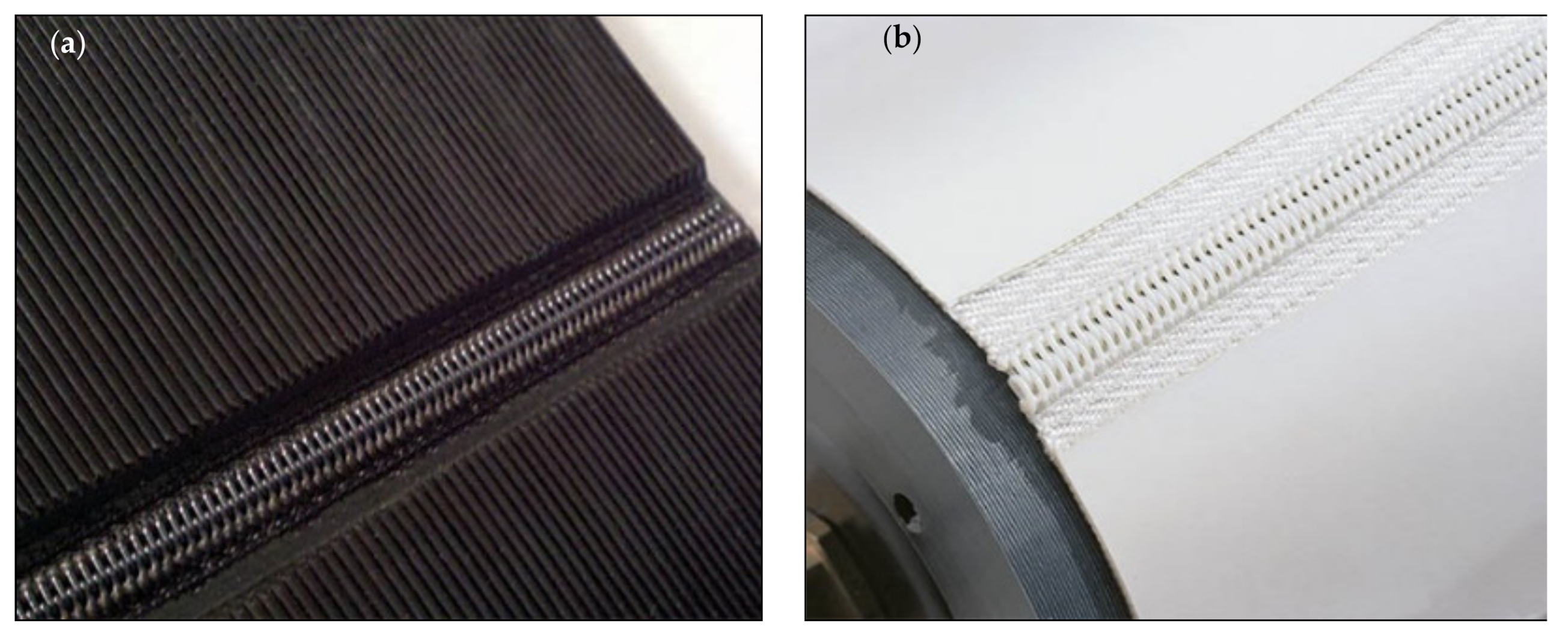
2.7. Detachable Sewn Fastener

An example is shown in Figure 21. For polyester belts. Application: with metal detectors, food or pharmaceutical processing (e.g., dough transport), X-ray equipment, baggage inspection, with delicate products. For belt applications with small pulleys that require non-metal and low-profile fasteners. Detachable connection thanks to a removable pin. Available with white or blue polyester (materials compliant with FDA—US Food Contact Materials Regulation), black polyester and PEEK (Polieteroeteroketon) for high temperature applications. It is recommended that the installation of the couplings be performed by a qualified workshop experienced in splicing the belt into a spiral lace.

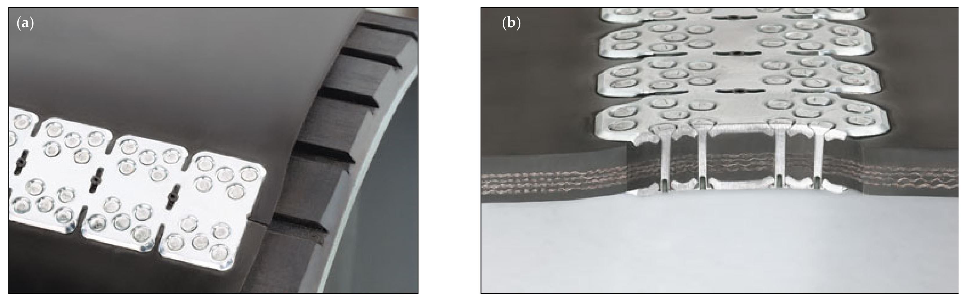
2.8. Solid Fastener with Rivets Attachment Method

An example that uses plates is shown in Figure 22. Application: sand, gravel, cement, in mining, crushed stone, coal, salt, grain transport (if plates are made of Everdur). Table 10, below, shows what the fasteners are resistant to, depending on the material with which it is made.
The plates can be non-sparking and non-magnetic when made from a material called Everdur. Installation is carried out using a special portable tool. Can be installed manually, but also using a pneumatic driver.

2.9. Solid Fastener with Bolts/Screws Attachment Method

An example is shown in Figure 23. Available in five material variants—Table 11.
The bolt solid plate connection is the solution to the toughest requirements of conveyor belts. Designed in the form of plates compressed on both sides by screws. The plates have special hooks (shown in Figure 23b) that are shaped so that they penetrate the belt without damaging the cover.
It is possible that the upper part is covered with rubber. This system can also be used in the arrangement of the so-called WEDLOK® for high tension splice. It uses standard connection plates, but additional special plates are supplied that allow a characteristic seam at a specific angle. Individual fasteners of this system can also serve as repair kits for broken conveyor belts.
The next example uses a rubber joint instead of metal plates—shown in Figure 24. Application: quarries, cement plants, and mines, if the fastener is made out of steel and gold mines, phosphate mines, sorting center, fertilizer plant, recycling facilities and salt handling if the fastener is made out of stainless steel. This fastener is available in several qualities of rubber, shown below in Table 12. Depending on this material, the fastener shows different resistance properties.
Structurally, it is a flexible rubber connector in which threaded screws are applied. Two rubber sheets are pre-connected with screws and spaced apart with plastic sleeves. A skived end of the belt is placed in the gap between the rubber panels. Special cutting and skiving tools are available for the installation.
An even better variation of the previous solution is the example in Figure 25. This is sort of a step forward from the standard solution. The difference is the use of inserts that act as washers for screws, whose number has been reduced, making installation easier and faster. The fastener integrates better with the belt, the strength has been improved, the abrasion resistance has been increased, and the lacing has been made more flexible. The is the possibility to use smaller pulley diameters.

3. Summary

The most important aspect in choosing the right fastener is the type of application—where and for which industry the conveyor will be used. The application can be for light, medium and heavy industry. This is related to the magnitude of the tensile stresses of the conveyor belt under the working load, and this in turn with the possibility of transferring given stresses through individual types of connections. An important aspect resulting from the above is also the type of transported goods and its relationship with the material of the conveyor belt and the material of the mechanical joint itself. If you are transporting food, your focus should be on FDA-approved conveyor belt materials such as TPU, PVC, PU, PES. These types of belts are more suitable for hook connections or one that is compatible with the conveyor belt material—a patch of identical material. If you are transporting metal parts that cannot react with other metal surfaces, choose a non-metallic connection material, e.g., plastic, Evedur, or non-magnetic stainless steel. If the transport area must be protected against fire, a non-sparking connection must be selected. An important geometric aspect on which the selection of the connection depends is the diameter of the pulley. For each fastener, the minimum pulley diameter at which the fastener can be used is given. However, the most important thing is that detachable connections can be applied to relatively smaller diameters than permanent connections.
The next aspect is how to install. This includes considerations such as whether it is an easy or difficult method, whether it requires special or simple equipment, whether it can be assembled manually or with the use of pneumatic/hydraulic/electric support, whether the connection must be made by yourself, whether it is possible at the manufacturer’s site, whether you need a small number of tools or a large number, whether commonly used or specialized tools.
You also need to consider what degree of cleanliness you want to maintain when using the conveyor. Some connections are unfortunate in this respect, as they have numerous cavities and openings in which dirt can enter. Belts with a detachable connection are better for cleaning. The belt can then be removed from the conveyor and cleaned outside the conveyor system.
If significant abrasive forces occur during use, then either choose a material for the fastener (e.g., MegAlloy) that is extremely abrasion resistant or use a rubber protection for the fasteners.
It is also worth paying attention to the thickness of the connection—whether it creates a low-profile system or not. This is very important, especially in the context of the relationship with additional devices mounted on the conveyor and having direct contact with the conveyor belt, such as a scraper.
Figure 26 shows the first design map, thanks to which it is possible to select a mechanical connection for a conveyor belt with a thickness of 0 to 18 mm and a fastener strength of 0 to 60 kN/m. The areas of application of individual connections are presented in the form of triangles, in which the hypotenuse is a curve approximating (as a linear function) the actual gradation of the relationship between the thickness of the belt and the strength of the connector in a given size. Some connections, on the other hand, are presented in the form of straight lines (as a constant function)—such as 3 and 7. This means that all connection sizes from a given group have the same strength, but are designed for different thicknesses of the belt.
Figure 27 shows the second design map, thanks to which it is possible to select a mechanical connection for a conveyor belt with a thickness of 0 to even 54 mm and a fastener strength of 0 to even 360 kN/m. These are for more demanding applications.
Figure 28 shows the third design map, thanks to which it is possible to select a mechanical connection for a conveyor belt with a MIN. Pulley diameter of 0 to 360 mm and a fastener strength of 0 to 60 kN/m. Some connections are not shown as triangular areas like 3 and 7. They are only indicated by the reference line. This means that they are only available in a size that has a certain constant strength and one value for the minimum drive roller diameter.
Figure 29 shows the fourth design map, thanks to which it is possible to select a mechanical connection for a conveyor belt with a MIN. Pulley diameter of 0 to 1350 mm and a fastener strength of 0 to 360 kN/m.
By reviewing the mechanical fasteners, it was possible to notice an extensive variety of design solutions. In summary, the following types of construction nodes are worth paying attention to when determining the optimal geometric and material properties of connections for further research, mainly in the context of interference with the internal structure of the belt:
  • Material: metal (mainly steel, but also light metals, such as titanium), non-metal (plastic, rubber).
  • Separable and non-separable.
  • Complexity: monolithic (uniform), several partial, with intermediate elements.
  • The method of integration with the belt (clamp form): teeth, legs, claws, spikes, hooks, screws, bolts, rivets, weld, pins, staples, nails, spiral lacing
  • Clamp pattern (selected): staples in a horizontal pattern, staples in a diagonal pattern, staples in a V-pattern, meander pattern, multi-row pattern, etc.
  • Belt preparation: with a one-sided initial skiving (material loss in the thickness of the belt), with a double-sided initial skiving, cutting the belt widthwise, cutting the belt diagonally (at a specific angle), form cut, pre-drilling, preliminary puncturing, etc.
  • Number of fasteners: number of bolts, number of rivets, number of staples, etc.
  • Effect of joint height on roll integrity and with e.g., scraper: low profile joints, normal joints, high profile joints, joints compatible with the belt thickness.
  • Complexity of connection techniques: only mechanical, hybrid (mechanical connection with any other, e.g., glued).
  • Surface contact with the belt (contact area of the contact surfaces of the joints with the top and bottom layers of the belt).
  • Type of belt penetration: material damage (puncture e.g., when riveting or screwing in screws), elastic/plastic deformation (e.g., by clamping the belt from shaped hooks).

Author Contributions

Conceptualization, K.K., D.W. and K.T.; methodology, K.K., D.W. and K.T.; software, K.K.; validation, K.K., D.W. and G.D.; formal analysis, K.K.; investigation K.K. and D.W.; resources, K.K., G.D.; data curation, K.K.; writing—original draft preparation K.K.; writing—review and editing, K.K., D.W., K.T., A.K. and G.D.; visualization, K.K.; supervision, K.T. and A.K.; project administration, K.K. All authors have read and agreed to the published version of the manuscript.

Funding

This research received no external funding.

Institutional Review Board Statement

Not applicable.

Informed Consent Statement

Not applicable.

Data Availability Statement

Data sharing not applicable.

Conflicts of Interest

The authors declare no conflict of interest.

References

  1. Goździecki, M.; Świątkiewicz, H. Przenośniki; Wydawnictwa Naukowo-Techniczne: Warszawa, Poland, 1979; ISBN 83-204-0081-3. [Google Scholar]
  2. Domek, G.; Wilczyński, M.; Woźniak, T. Application of flat belts in advanced machine constructions. Mechanik 2017, 90, 1048–1050. [Google Scholar] [CrossRef] [Green Version]
  3. Guzha, E.D.; Romanenko, V.A.; Skorokhod, M.A. Simulation and histogram modeling of conveyor systems. In IOP Conference Series: Materials Science and Engineering, Mechanical and Automation Engineering for Industry 2020; MIP: Engineering-2020; IOP Publishing: Bristol, UK, 2020; Volume 862, p. 032008. [Google Scholar] [CrossRef]
  4. Kawalec, W.; Suchorab, N.; Konieczna-Fuławska, M.; Król, R. Specific Energy Consumption of a Belt Conveyor System in a Continuous Surface Mine. Energies 2020, 13, 5214. [Google Scholar] [CrossRef]
  5. Kozhushko, G.G.; Yampolsky, D.A.; Lukashuk, M.D. Analysis of forced vibrations of conveyor belts. In IOP Conference Series: Materials Science and Engineering, International Conference on Modern Trends in Manufacturing Technologies and Equipment 2020; ICMTMTE; IOP Publishing: Bristol, UK, 2020; Volume 709, p. 033022. [Google Scholar] [CrossRef]
  6. Rudawska, A.; Madlenák, R.; Madlenáková, L.; Droździel, P. Investigation of the Effect of Operational Factors on Conveyor Belt Mechanical Properties. Appl. Sci. 2020, 10, 4201. [Google Scholar] [CrossRef]
  7. Pihnastyi, O.; Khodusov, V. Neural model of conveyor type transport system. In CEUR Workshop Proceedings; 2020; Available online: https://www.researchgate.net/publication/342667146_Neural_model_of_conveyor_type_transport_system (accessed on 12 December 2020).
  8. Boslovyak, P.V.; Lagerev, A. Optimization of the conveyor transport cost. IFAC-PapersOnLine 2019, 52, 397–402. [Google Scholar] [CrossRef]
  9. Wheatley, G. Design of a Conveyor Belt Turning Frame. In Industrial Engineering & Management; 2018; Volume 7, ISSN 2169-0316. Available online: https://www.researchgate.net/publication/339615559_design-of-a-conveyor-belt-turning-frame (accessed on 12 December 2020). [CrossRef]
  10. Wojtkowiak, D.; Talaśka, K.; Malujda, I.; Domek, G. Estimation of the perforation force for polymer composite conveyor belts taking into consideration the shape of the piercing punch. Int. J. Adv. Manuf. Technol. 2018, 98, 2539–2561. [Google Scholar] [CrossRef] [Green Version]
  11. Wojtkowiak, D.; Talaśka, K. Determination of the effective geometrical features of the piercing punch for polymer composite belts. Int. J. Adv. Manuf. Technol. 2019, 104, 315–332. [Google Scholar] [CrossRef] [Green Version]
  12. Wojtkowiak, D.; Talaśka, K.; Wilczyński, D. Evaluation of the belt punching process efficiency based on the resistance force of the compressed material. Int. J. Adv. Manuf. Technol. 2020, 110, 717–727. [Google Scholar] [CrossRef]
  13. Ahad, N.A. A Recent blend of thermoplastic polyurethane (TPU), Conference Paper in IOP Conference Series Materials Science and Engineering. In Proceedings of the IOP Conference Series: Materials Science and Engineering, International Conference on Sustainable Materials (ICoSM 2020), Pahang, Malaysia, 30 March 2020. [Google Scholar] [CrossRef]
  14. Xu, T.; Shen, W.; Lin, X.; Xie, Y.M. Mechanical Properties of Additively Manufactured Thermoplastic Polyurethane (TPU) Material Affected by Various Processing Parameters. Polymers 2020, 12, 3010. [Google Scholar] [CrossRef] [PubMed]
  15. Wojtkowiak, D.; Talaśka, K.; Malujda, I.; Domek, G. Vacuum conveyor belts perforation—methods, materials and problems. Mechanik 2017, 90, 1138–1142. [Google Scholar] [CrossRef] [Green Version]
  16. Romanchev, I.O. The mathematical model of the belt conveyor. In Proceedings of the IOP Conference Series: Materials Science and Engineering, International Conference on Mechanical Engineering, Automation and Control Systems 2018, Novosibirsk, Russia, 12–14 December 2018; Volume 560, p. 012035, MEACS2018. [Google Scholar] [CrossRef]
  17. Li, J.; Pang, X. Belt Conveyor Dynamic Characteristics and Influential Factors, Hindawi. Shock. Vib. 2018, 2018, 8106879. [Google Scholar] [CrossRef] [Green Version]
  18. Ibishi, I.; Latifi, A.; Ibishi, G.; Sejdiu, K.; Shala-Galica, M.; Latifi, B. Calculation of tension force of belt conveyor. Int. J. Eng. Sci. Technol. 2012, 4, 4886–4892. [Google Scholar]
  19. Trufanova, I.S.; Avksentiev, S.Y. Mathematical model of belt conveyor intermediate drive with baffles. In Proceedings of the IOP Conference Series: Earth and Environmental Science, International Conference on Innovations and Prospects of Development of Mining Machinery and Electrical Engineering 2019, Saint-Petersburg Mining University, Saint-Petersburg, Russia, 24–27 April 2019; Volume 378, p. 012033, IPDME 2019. [Google Scholar] [CrossRef]
  20. Hussein, E.K. Belts Systems, Types of Belts Systems (Flat Belt Drives), ATU, TCM. In Theory of Machines—Belts Drives; 2016; Available online: https://www.researchgate.net/publication/307431645_BELTS_SYSTEMS_TYPES_OF_BELTS_SYSTEMS_FLAT_BELT_DRIVES (accessed on 12 December 2020).
  21. Finnegan, K. Selecting Plate-Type Belt Fastener systems for Heavy-Duty conveyor-Belt Operations, Bulk Solids Handling. Sel. Belt Fasten. Syst. 2001, 21, 315–319. [Google Scholar]
  22. Markowski, M. Przenośniki cz. 1; Wydawnictwo Politechniki Łódzkiej: Łódź, Poland, 1995; ISBN 8386453443. [Google Scholar]
  23. Group Work. Katalog Przenośników Taśmowych KPT-3; Wydawnictwo Centralnego Biura Konstrukcji Maszynowych: Bytom, Poland, 1962. [Google Scholar]
  24. Website of the HABASIT AG, Manufacturer of Conveyor Belts. Available online: www.habasit.com (accessed on 12 December 2020).
  25. Website of the FLEXCO, Manufacturer of Fastening System for Conveyor Belts. Available online: www.flexco.com (accessed on 12 December 2020).
  26. Website of the MLT, Manufacturer of Fastening System for Conveyor Belts. Available online: www.mlt-lacing.com (accessed on 12 December 2020).
Figure 1. Structural diagram of a belt conveyor with the use of a mechanical connector. Structural description in the text of the article. Other markings: α—angle of contact the roller by the conveyor belt, δ—the lower belt deflection angle, which is the same as the angle between the force vectors in the upper and lower conveyor belt, S1—force in the upper band, S2—force in the lower band, P—driving force, d—diameter of the roller, θ—angle of deviation of the vector of the resultant force loading the shaft. (Detail A and Detail B are shown in the following drawings).
Applsci 11 02916 g001
Figure 2. Scheme for calculating the inclination angle θ of the resultant force vector Q.
Applsci 11 02916 g002
Figure 3. Stress distribution in the roller-belt-mechanical fastener configuration during: (left) ramp-up, (right) circulating around the roll. Explanations: FR—radial force during the run-up, F′R—radial force while going around the roller, FT—tangential force during the run-up, F′T—tangential force while going around the roller (which is the same as the friction force on the bottom surface of the joint), FTR—transverse force, FL—longitudinal force.
Applsci 11 02916 g003
Figure 4. Cross-section of the fastener showing the forces loading the components of the mechanical fastener itself. Explanations: 1—connector/link, 2—upper joint plate, 3—lower joint plate, 4—one end of the conveyor belt, 5—the other end of the belt.
Applsci 11 02916 g004
Figure 5. Drawing summarizing the analytical evidence that the minimum roll diameter requirement in the context of two conveyor systems with the same loading parameters is in fact a geometric problem: (a) a larger diameter roll, (b) a smaller diameter roll. Explanation: ζ—opening angle of the hinge connection plates in the arrangement with the larger roller, κ—opening angle of the hinge connection plates in the arrangement with the larger roller, D—larger diameter, d—smaller diameter, S—force in the tendon (green), FT—tangential force (blue), FR—radial force (red), R—the force of reaction (yellow) that actually causes the staples to detach from the joint.
Applsci 11 02916 g005
Figure 6. Mechanical Lace: (a) fastener in cobalt blue, size 1”; (b) fastener in white, size 2” [24].
Applsci 11 02916 g006
Figure 7. SaniClip: (a) general view, (b) hinge pin connected to a yellow stick [24].
Applsci 11 02916 g007
Figure 8. Staple fastening: (a) general view; (b) single fastener [25].
Applsci 11 02916 g008
Figure 9. Staple fastening: (a) general view; (b) top view of the fastener [26].
Applsci 11 02916 g009
Figure 10. Staple fastening: (a) general view; (b) side view [25].
Applsci 11 02916 g010
Figure 11. Plastic rivet fastening: general view [25].
Applsci 11 02916 g011
Figure 12. Rivet fastening: (a) general view; (b) individual items [25].
Applsci 11 02916 g012
Figure 13. Rivet fastening: cross section view [25].
Applsci 11 02916 g013
Figure 14. Bolt fastening: (a) general view, (b) single fastener [25].
Applsci 11 02916 g014
Figure 15. Wire hook fastening: (a) welded to a common rod; (b) carded [25].
Applsci 11 02916 g015
Figure 16. Laundry patch hooks fastening: (a) single fastener, (b) after mounting [25].
Applsci 11 02916 g016
Figure 17. Metal legs fastening: (a) general view; (b) fastener installed on the belt [25].
Applsci 11 02916 g017
Figure 18. Metal legs fastening: (a) general view on the belt; (b) single string of fasteners [25].
Applsci 11 02916 g018
Figure 19. Metal teeth fastening: (a) general view; (b) single string of mechanical fasteners [26].
Applsci 11 02916 g019
Figure 20. Metal clamps fastening: general view [26].
Applsci 11 02916 g020
Figure 21. Sewn fastening: (a) black lacing; (b) white lacing [25].
Applsci 11 02916 g021
Figure 22. Rivet solid plate fastening: (a) general view using five contact points at each end of the belt; (b) cross section view using seven contact points at each end of belt [25].
Applsci 11 02916 g022
Figure 23. Bolt solid plate fastening: (a) general view, (b) single fastener [25].
Applsci 11 02916 g023
Figure 24. Screws rubber splice fastening: (a) one end of the belt attached, (b) suitable for trough systems of rollers of a belt conveyor [26].
Applsci 11 02916 g024
Figure 25. Screws rubber splice fastening: (a) general view; (b) view of the screw embedded in a insert with hooks [26].
Applsci 11 02916 g025
Figure 26. Design map for the selection of a mechanical connection in the range of conveyor belt thickness from 0 to approximately 18 mm and in the range of fastener strength from 0 to approximately 60 kN/m.
Applsci 11 02916 g026
Figure 27. Design map for the selection of a mechanical connection in the range of conveyor belt thickness from 0 to approximately 54 mm and in the range of fastener strength from 0 to approximately 360 kN/m.
Applsci 11 02916 g027
Figure 28. Design map for the selection of a mechanical connection in the range of MIN. Pulley diameter from 0 to approximately 360 mm and in the range of fastener strength from 0 to approximately 60 kN/m.
Applsci 11 02916 g028
Figure 29. Design map for the selection of a mechanical connection in the range of MIN. Pulley diameter from 0 to approximately 1350 mm and in the range of fastener strength from 0 to approximately 360 kN/m.
Applsci 11 02916 g029
Table 1. Fasteners resistant ranging from one plus sign (+) to four plus signs (+ + + +) [25].
Material of Fastener.MagneticAbrasion
Resistant
Chemical
Resistant
Rust
Resistant
Galvanized SteelNo+ + +++ +
316 Stainless SteelYes+ + ++ + ++ + + +
430 Stainless SteelNo+ + ++ ++ + +
MegAlloy®No+ + + +++
Table 2. Hinge pins various materials and different applications [25].
Material of PinType of FastenerRecommended forPicture
NC—Nylon Covered Steel Cablesteelfor troughing or flat belt conveyors Applsci 11 02916 i001
NCS—Nylon Covered Stainless Steel Cablestainless steel, MegAlloy®for extra abrasion and chemical resistance Applsci 11 02916 i002
SS—Stainless Steel Spring Wirestainless steelflat belts only Applsci 11 02916 i003
SP—Steel Spring Wiresteelin abrasive or gritty
material applications
Applsci 11 02916 i004
Table 3. Material variants of the plastic rivets fastening [25].
ColorPropertiesPicture
BlackUV—resistant for extended life in outdoor applications Applsci 11 02916 i005
WhiteFDA-accepted material resists weak acids, alkali, hydrocarbons, ester solvents, and alcohols Applsci 11 02916 i006
BlueFDA-accepted material with the same resistance as the white offering but colored blue to match blue belts used in many food applications Applsci 11 02916 i007
Table 4. Fasteners resistant ranging from one plus sign (+) to four plus signs (+ + + +) [25].
Material of FastenerMagneticAbrasion ResistantChemical ResistantRust Resistant
Galvanized SteelYes+ + +++ +
300 Stainless SteelSlightly+ + ++ + ++ + + +
MegAlloy®Yes+ + + +++
RustAlloy®Yes+ + ++ + ++ + +
Table 5. Hinge pins various materials and different applications [25].
Material of PinApplicationsPicture
AC—Bar Armored CableHeavy-duty, longwearing pin popular in underground mining applications. Armor wrapping protects interior wires. Applsci 11 02916 i008
ACS—Bar Armored Stainless CableThe same advantages as bare armored cable plus corrosion resistance Applsci 11 02916 i009
NAC—Nylon Covered Armored CableCombines a durable armored steel wrap with a nylon covering for smooth operation and long service life. Nylon covering prevents pin migration. Not recommended in wet, abrasive applications. Applsci 11 02916 i010
NC—Nylon Covered Steel CableNylon covering prevents pin migration. Not recommended in wet, abrasive applications. Applsci 11 02916 i011
NCS—Nylon Covered Stainless CableFor greater corrosion resistance. Not recommended in wet, abrasive applications. Applsci 11 02916 i012
SC—Bar Steel CableRecommended for abrasive or gritty material conveyance. Applsci 11 02916 i013
SSC—Bar Stainless Steel CableFor conditions where corrosion attacks steel pins. Applsci 11 02916 i014
Table 6. Hinge pin types with regard to the application [25].
Material of PinRecommended for
NC—Nylon Covered Steel Cablereduces corrosion and simplifies hinge pin insertion
NCS—Nylon Covered Stainless Steel Cablegreater corrosion resistance
SC—Bare Steel Cablerecommended for abrasive or gritty material conveyance
SSC—Bare 300 Series Stainless Steel Cableconditions where corrosion attacks ordinary steel pins
Table 7. Fastener Material Characteristics ranging from one plus sign (+) to four plus signs (+ + + +) [25].
Material of FastenerMagneticAbrasion ResistantChemical ResistantRust Resistant
Galvanized SteelYes+ + +++ +
300 Stainless SteelSlightly+ + ++ + ++ + + +
MegAlloy®Yes+ + + +++
EverdurNo+++
Table 8. Fastener Material Characteristics ranging from one plus sign (+) to four plus signs (+ + + +) [25].
Material of FastenerMagnetic
Resistance
Abrasion
Resistant
Chemical
Resistant
Rust
Resistant
Galvanized SteelYes+ + +++ + +
Coated SteelTM/SteelYes+ + +++ + +
High Tensile SteelYes+ + + ++ ++ + +
Rectangular High Tensile SteelYes+ + + ++ ++ + +
430 Stainless SteelYes+ + ++ + ++ + +
316L Stainless SteelSlightly+ + ++ + + ++ + + +
Monel® 400Slightly+ ++ + + ++ + + +
Inconel® 600No+ ++ + + ++ + + +
Phosphor BronzeNo+ + +++ + +
Hastelloy C-22No+ + ++ + + ++ + + +
Black Oxide SteelYes+ + +++ +
Table 9. Connecting pin types for the wire hook fastening [25].
Material of PinDiameter of Pin [mm] (inch)Picture
DuraStainlessTM—DSS1.7 (0.065)
2.4 (0.093)
2.8 (0.109)
3.2 (0.125)
4.0 (0.156)
Applsci 11 02916 i015
DuralinkTM—DL Applsci 11 02916 i016
Nylosteel—NY Applsci 11 02916 i017
Nylostainless—NYS Applsci 11 02916 i018
Nylon-Covered-Cable—NCS Applsci 11 02916 i019
Nylon Plus—NP Applsci 11 02916 i020
Table 10. Fastener Material Characteristics ranging from one plus sign (+) to four plus signs (+ + + +) [25].
Material of FastenerMagneticAbrasion ResistantChemical ResistantRust Resistant
Galvanized SteelYes+ + +++ +
400 Stainless SteelYes+ + ++ ++ + +
300 Stainless SteelSlightly+ + ++ + ++ + + +
MegAlloy®Yes+ + + +++
EverdurNo+++
Table 11. Fastener Material Characteristics ranging from one plus sign (+) to four plus signs (+ + + +) [25].
Material of
Fastener
MagneticAbrasion
Resistant
Chemical
Resistant
Rust
Resistant
Picture
SteelYes+ + +++ Applsci 11 02916 i021
300 Stainless SteelSlightly+ + ++ + ++ + + + Applsci 11 02916 i022
MegAlloy®Yes+ + + +++ Applsci 11 02916 i023
EvedurNo+++ Applsci 11 02916 i024
Rubber-Covered SteelYes+ + + +++ Applsci 11 02916 i025
Table 12. Several qualities of rubber splice [26].
Variant NameParameter Description
Abrasion Resistantwith a high resistance of rubber abrasion to 50 mm3
Heat Resistantin systems with temperatures up to 150 °C (302 °F) continuous and 170 °C (338 °F) flash
Heat Retardantwill withstand from 170 °C continuous (338 °F) to 200 °C (392 °F) flash
Oil Retardantfor surfaces which require oil and solvent resistance
Fire Resistantfabricated in accordance with ISO 340 and ISO 284, ensures security of silos and underground mines in fire-resistant and antistatic environments
Very low temperatureresists even at low temperatures until −30 °C (−22 °F) −50 °C (−58 °F) on demand
Publisher’s Note: MDPI stays neutral with regard to jurisdictional claims in published maps and institutional affiliations.

