1. Introduction
In recent years, backfilling mining techniques have developed rapidly in China. Backfilling mining works well to control strata movement and is capable of reducing overburden subsidence, increasing the extraction rate of coal resources, and alleviating the environmental disruption caused by mining. Focusing on issues such as environmental protection and coal mining under buildings, railways, and water bodies, scientific researchers both in China and other countries have conducted numerous experimental studies on backfilling mining and made a series of progress [
1,
2,
3,
4]. Coarse-grained wastes (from both mining and processing) are used as backfilling material in Poland [
5]. The need for backfilling is a major issue in Australia, where 10 million cubic meters of underground voids are generated annually as a result of mining [
6]. Mukhopadhyay and Sinha attempt to provide a mathematical model while ensuring maximization of backfilled land area at minimum direct and economic costs in India [
7]. A method is described that allows for a prospective evaluation of these backfilling materials [
8]. A novel short-wall caving zone backfilling technique for controlling mining subsidence has been proposed [
9]. At present, there are paste backfilling [
10,
11], solid backfilling [
12,
13], high water material backfilling [
14,
15], slurry backfilling [
16,
17], and many other backfilling mining techniques.
However, backfilling technology in a goaf also presents a series of problems, such as large consumption of backfilling material, slow advance speed, low production efficiency, and high comprehensive backfilling cost. A suitable partial backfilling method to achieve lower backfilling cost and higher backfilling efficiency is urgently needed. On the basis of the longwall strip filling method and spaced strip filling mining method proposed by Xu et al. [
18,
19], a longwall pier-column backfilling method has been creatively developed by the Wangzhuang coal mine in Zibo, China. The schematic diagram is shown in
Figure 1. In the goaf, the piers are filled at certain intervals, and each independent pier supports the overlying strata to control the overburden subsidence. In this method, the single hydraulic props are firstly used to support the roof of the goaf after mining (
Figure 2a), and then the slurry material is used to fill the pier-column bags. The single hydraulic props are withdrawn when the pier-columns reach a certain solidification strength (
Figure 2b), and then the backfilling process is carried out in turn.
With the passage of time, the Wangzhuang coal mine is about to shift to a new mining area. The mining height and width of the backfilling working face in the new mining area are both larger than those of the previous backfilling working faces. For this reason, it is necessary to analyze how changes in the geometric dimensions of the working face influence the control effect of overburden subsidence in pier-column backfilling, laying a scientific foundation for evaluating the backfilling effect in the future.
2. Numerical Simulation
According to the field working face conditions [
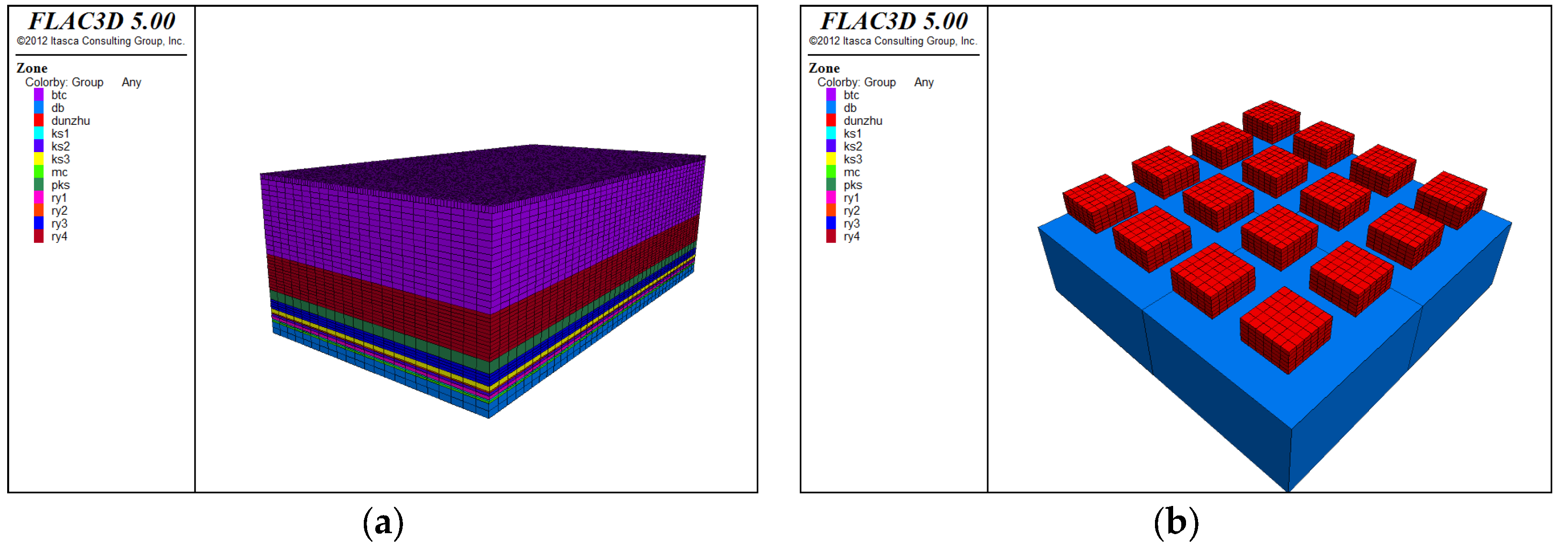
20], the coal seam in the mining area of the Wangzhuang coal mine had a very small dip angle of less than 5 degrees; hence, the coal seam, as well as the overburden, were set as horizontal in the numerical model. In this FLAC3D model, the plane of the pier-column was a square with a side length of 6 m. The interval of the pier-columns was equal in row and column directions, both of which were 4 m.
Parameter settings of the numerical simulation: geometric similarity ratio: 1:1; model length: 800 m; model width: 440 m; model height: 263 m; coal seam floor elevation: z = 0 (
Figure 3). The model was composed of about 915,560 block elements and 1,083,742 grid nodes.
This model was primarily used to study the reduction effect of overburden subsidence in longwall pier-column backfilling, simplify the overlying strata and floor where necessary, and assigning rock mechanics parameters according to corresponding strata.
Table 1 shows the mechanical parameters of the numerical model.
The control variable method was used to qualitatively investigate the influence of mining height and width on the control effect of overburden subsidence. We performed simulations using 25 condition combinations (five different mining heights (1 m, 1.5 m, 2 m, 2.5 m, and 3 m) × five different mining widths (80 m, 120 m, 160 m, 200 m, and 240 m)). See the numerical simulation schemes in
Table 2.
According to the numerical simulation of strata movement, we explored the qualitative relationships of overburden subsidence with different mining heights and widths in longwall pier-column backfilling.
In
Figure 4, the first number in the legend denotes the mining width of the working face, and the second number in the legend denotes its mining height. Taking a mining width of 80 m as an example, when mining height changed from 1 m to 1.5 m, the maximum overburden subsidence increased by a factor of 1.9 times from 65.61 mm to 121.63 mm; when mining height changed from 1.5 m to 2 m, the maximum overburden subsidence increased by a factor of 1.1 times to 130.38 mm; when mining height changed from 2 m to 2.5 m, the maximum overburden subsidence increased by a factor of 1.02 times to 133.07 mm; when mining height changed from 2.5 m to 3 m, the maximum overburden subsidence increased by a factor of 1.02 times to 135.28 mm.
As can be observed from the above discussion, given the mining width of the working face, a mining height less than 1.5 m had a significant influence on the overburden subsidence. Each time the mining height increased, the overburden subsidence increased markedly. When the mining height exceeded 1.5 m, the overburden subsidence increased only slightly with increasing mining height. This suggests that, at a mining height of above 1.5 m, the influence of mining height on overburden subsidence tends to be stable.
In
Figure 5, the first number in the legend denotes the mining width of the working face, and the second number in the legend denotes its mining height. Taking a mining height of 2 m as an example, when mining width changed from 80 m to 120 m, the maximum overburden subsidence increased by a factor of 2.3 times from 130.28 mm to 298.48 mm; when mining width changed from 120 m to 160 m, the maximum overburden subsidence increased by a factor of 1.8 times to 539.31 mm; when mining width changed from 160 m to 200 m, the maximum overburden subsidence increased by a factor of 1.5 times to 832.88 mm; when mining width changed from 200 m to 240 m, the maximum overburden subsidence increased by a factor of 1.4 times to 1191.56 mm.
According to the above discussion, given the mining height of the working face, each time the mining width of the working face increased, the overburden subsidence increased significantly. This reveals that mining width has a significant negative influence on the overburden subsidence.
3. Physical Simulation
To further study and demonstrate the influence of the working face mining dimensions on the reduction effect of overburden subsidence, according to the rock structure of 8–15 borehole histogram in No.7 mining area of Wangzhuang coal mine [
20], we used a plane stress model 2500 × 200 × 2000 mm (length × width × height) in size to make a physical similarity simulation, in order to simulate the process of pier-column backfilling after mining and monitor the overburden subsidence rules for pier-column backfilling.
The similarity ratios of the physical model were referred to by Xie et al., 2016 [
20]. The simulation model was only paved to the position of the primary key stratum (PKS). There is a key stratum when it breaks all of the strata above will subside simultaneously, and then it will be defined as primary key stratum (PKS) [
21]. The unpaved overlying strata above PKS was replaced by external hydraulic cylinder loading. The load required to apply can be calculated from Equation (1):
where
F is the hydraulic cylinder pressure, KN;
is the density of rock strata, generally set as 2500 kg/m3;
H is the height of unpaved rock strata, m;
L is the length of the model, m;
W is the width of the model, m.
After setting the model parameters (L = 2.5 m, W = 0.2 m, h = 188.63 m), the load required to apply hydraulic cylinder loading was calculated to be F = 30.23 KN. To ensure model stability during pressurization, two steel channels were mounted before and after the model for protection.
Two physical experiment schemes with the same working face conditions (except mining height) were developed. In
Figure 6a, the coal seam had a mining height of 2 cm as similar in-site size 1 m; in
Figure 6b, it had a mining height of 4 cm as similar in-site size 2 m.
The schematic diagram of pier-columns backfilling in the physical model is shown in
Figure 7. A 21.5 cm coal pillar was reserved on both sides of the model to ensure the similarity of boundary conditions. The size of the backfilling pier-columns was 7.5 × 7.5 cm (length × width), different heights were 2 and 4 cm, respectively, and a row of backfilling pier-columns was arranged in the advancing direction. The row and column spaces were both set as 12 cm. See the mining and backfilling process in the physical simulation in
Figure 8.
To study the control effect of overburden subsidence in pier-column backfilling, it is necessary to observe strata movement. In this experiment, a DigiMetric 3D photogrammetric system (with a precision of less than 0.1 mm/4 m) was adopted to measure the strata movement in the model. Measuring points were horizontally laid out in the middle of four key strata (KS) (from the bottom up are KS1, KS2, KS3, and PKS) with a horizontal spacing of 5 cm, creating four measuring lines from down to up (namely L1 to L4, each line with 49 points). See the measuring points layout in
Figure 9.
As can be seen from the overburden subsidence curves, in the excavation and backfilling of the coal seam, the subsidence of key strata gradually decreased from the bottom up, and the maximum subsidence point moved forward along with mining. The majority of subsidence was caused by the initial space between the backfilling body and the roof. To observe the overburden subsidence control effect after stabilization, strata movement was measured once on the day after the model was finished, and the subsidence curves are shown in
Figure 10 and
Figure 11.
It can be seen from
Figure 10 that in the 2 cm mining height model, the curves of strata movement at the mining widths of 102 cm and 204 cm (the similar in-site size are 51 m and 102 m) were compared. As can be known from
Figure 10b that when the mining width of the working face was 102 cm, KS1, KS2, KS3, and PKS subsided by 1.8, 1.1, 0.8, and 0.7 mm, respectively. According to
Figure 10d, when the mining width of the working face reached 204 cm, KS1, KS2, KS3, and PKS subsided by 4, 3.4, 3, and 2.3 mm, respectively. In the 2 cm mining height model, due to an increase of the mining width, the subsidence of each stratum increased to some extent, but various overlying stratum had good integrity and uniformly showed slight bending subsidence.
The subsidence trend of overlying strata in the 4 cm mining height model was the same as that of the model with 2 cm mining height. The subsidence curves are in
Figure 11.
Similarly, in the 4 cm mining height model, the curves of strata movement with mining widths of 102 cm and 204 cm were compared. As can be known from
Figure 11c, when the mining width of the working face was 102 cm, KS1, KS2, KS3, and PKS subsided by 2.7, 1.7, 1.3, and 1.1 mm, respectively. According to
Figure 11d, when the mining width of the working face reached 204 cm, KS1, KS2, KS3, and PKS subsided by 6.3, 4.6, 4.3, and 3.8 mm, respectively. In the 4 cm mining height model, due to an increase in the mining width, the subsidence of each overlying stratum increased to some extent. It is thus clear that mining width has an obvious influence on overburden subsidence control in longwall pier-column backfilling.
As can be known from a comparison of
Figure 10 and
Figure 11 that when strata movement stabilized, the subsidence values of various key strata in the 4 cm mining height model were uniformly greater than those in the 2 cm mining height model. To be specific, the maximum subsidence values of KS1, KS2, and KS3 increased by 2.3, 1.2, and 1.3 mm, respectively. The maximum subsidence value of PKS increased by 1.5 mm. Furthermore, in the 4 cm mining height model, when strata movement stabilized, KS1 contained a vertical crack (
Figure 12); in contrast, in the 2 cm mining height model, various strata had good integrity. It can be concluded that mining height has a significant influence on the overburden subsidence control effect in longwall pier-column backfilling and that the larger the mining height, the weaker the control effect of overburden subsidence.
4. Conclusions
(1) As can be discovered from numerical simulation and physical experiments, given the mining width of the working face and the parameters of pier-columns in longwall pier-column backfilling, a mining height within a certain range has a significant influence on and is negatively correlated with the control effect of overburden subsidence. After mining height exceeds a certain value, its influence on overburden subsidence declines. In comparison, mining width has a significant influence, and each time mining width increases, the overburden subsidence increase markedly.
(2) When the mining height is 1 m and the mining width is 80 m, the size of the pier-column is 6 × 6 m and the spacing is 4 m, it will have a good reduction effect of overburden subsidence in pier-column backfilling.
(3) When the mining dimensions of the backfilling working face change, it is necessary to design more reasonable parameters for pier-column backfilling so as to ensure that pier-columns can achieve a better reduction effect of overburden subsidence. This part of the work needs to be further studied.


