1. Introduction
The concept of transformation electromagnetics/optics (TE/TO), introduced by Pendry et al. [
1] and Leonhardt [
2], refers to the manipulation of electromagnetic fields through a complex electromagnetic medium whose constitutive parameters are distinctly determined by the transformation. The transformation-based approach has led to numerous electromagnetic passive device designs [
3,
4,
5,
6,
7,
8,
9,
10,
11] that exhibit unconventional and unusual propagation characteristics. This technique is based on the key assumption of form-invariance of Maxwell’s equations under coordinate transformations [
12].
The same coordinate transformation technique can also be applied to a region with sources (e.g., current and charge distributions), where the sources will be transformed along with the material and behave exactly the same way as the original untransformed source [
13,
14,
15]. The use of source transformations yields fascinating opportunities for the design of complex radiation structures by enabling the fabrication of unique structures with engineered material properties, allowing the transformed geometries to mimic the performance of original ones, which is especially useful when physical constraints require spatial changes to be made to the source. One of the first applications of this technique was suggested by Luo et al. [
13], who transformed a dipole current source into a completely new distribution while preserving its properties as a dipole antenna. Kundtz et al. [
14] took this concept further and introduced an optical source transformation using a “pinwheel” transformation, where they approximated the sheet current of a simple dipole as a volume current and transformed it to a new current distribution using a “pinwheel” coordinate transformation. Based on these pioneering works, several conformal arrays have been proposed [
16,
17,
18]. Popa et al. [
16] proposed a conformal array design, where a nonuniform circular array radiates as a uniformly spaced linear array. Kwon [
17] proposed a TO-based circular array design, which performs as a series of line sources embedded in a rectangular metamaterial media. However, these designs used “point” charges or electric line sources as the radiating sources in their numerical solution to validate their proposed concept. A more practical antenna source was not considered in these TO-based phased array designs.
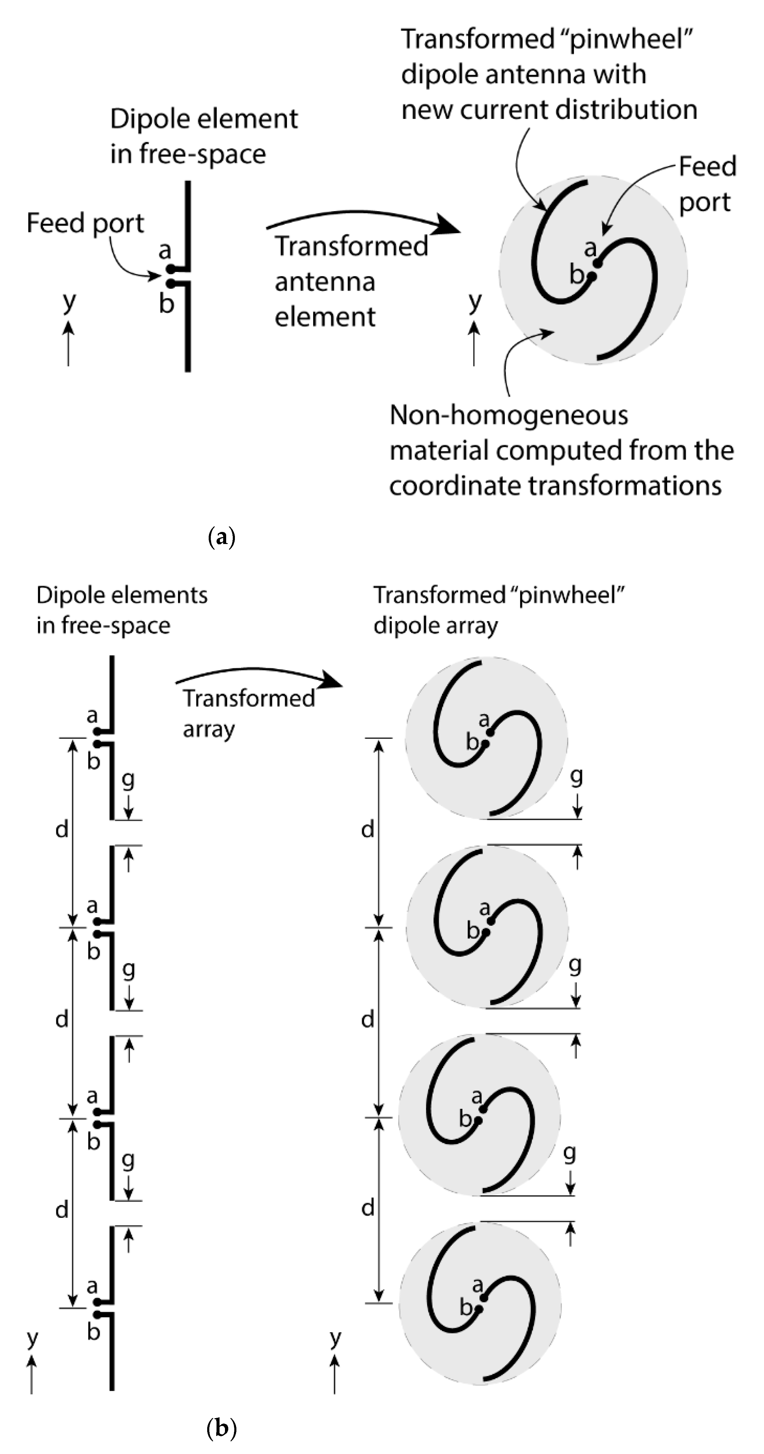
In this paper, the source transformation approach is used to design a new linear array, where each individual antenna element is transformed from a single dipole element in free-space (as shown in
Figure 1a). The result is an antenna array that radiates the same field as the linear dipole array depicted in
Figure 1b. As shown in
Figure 1a, the individual antenna element of the transformed linear array is a relatively extreme demonstration of a “pinwheel” shaped antenna which is transformed from a dipole antenna element similar to the transformation introduced in [
14]. Furthermore, the transformed antenna element in the array is surrounded by a complex electromagnetic media as prescribed by the transformation (shown as dotted grey circle in
Figure 1). Specifically, through numerical simulations, it is shown that a linear array of complex “pinwheel” antenna elements can perform as an array of linear dipole antennas in free-space for potential applications in structurally integrated and conformal phased arrays, where the antenna performance is a function of structural and mechanical restraints. The finite element analysis (FEA)-based full-wave simulations via COMSOL Multiphysics
® are used to numerically analyze and demonstrate the performance of the proposed TO-based antenna array for phased array scanning. The proposed “pinwheel” antenna array has potential applications in structurally integrated and conformal phased array antennas where the antenna performance is a function of structural and mechanical restraints. The “pinwheel” transformation shows that with the approach of the transformation electromagnetics/optics, it is possible to design electromagnetic structures and devices of many different complex and arbitrary geometries. Antennas designed in this way have many advantages compared to standard dipole antennas. A “pinwheel”-shaped antenna can be embedded into transformed regions to avoid interference, such as the cloak. The “pinwheel”-shaped antenna may also make use of the inherent properties of metamaterials to meet unique design parameters. For instance, a transformation designed antenna such as a “pinwheel”-shaped antenna may have less overall metal than a standard dipole antenna. The natural dispersion of metamaterials may then result in an antenna that interferes only very weakly at frequencies away from its frequency of operation. Under certain circumstances, the overall weight of the antenna may also be reduced compared to standard dipole antennas.
2. Theoretical Model of “Pinwheel” Antenna Array
Next, consider the N-element dipole phased array along the y-axis represented in
Figure 1b (left) and positioned in free-space, denoted as the “reference array”. Each of the elements in the “reference array” are equally spaced with the edge-to-edge distance between the elements of
where
is the free-space wavelength at which the phased array is designed to operate. A two dimensional (2D) space is considered to illustrate the proposed “pinwheel” array.
The current distribution of each of the elements from the “reference array” is defined by , where is used to approximate the current distribution on a thin wire at and , and is the phase between the adjacent antenna elements. In this case, an array of four elements is chosen to validate the proposed method.
Figure 1.
Proposed material-embedded antenna array using TO technique: (a) “pinwheel” transformation of a single dipole antenna element with TO-embedded media; (b) transformation of linear dipole array (reference array) (left) into a linear array of “pinwheel” antenna elements (right).
Figure 1.
Proposed material-embedded antenna array using TO technique: (a) “pinwheel” transformation of a single dipole antenna element with TO-embedded media; (b) transformation of linear dipole array (reference array) (left) into a linear array of “pinwheel” antenna elements (right).
Each of the dipoles in the “reference array” is of
length spanning over a distance of
. We intend to transform the reference array into a linear array of equidistant complex geometry antennas, where each antenna element of the “reference array” will be transformed into a “pinwheel”-shaped antenna, as shown in
Figure 1b. The first task is to transform the individual dipole elements of the “reference array” into a “pinwheel”-shaped antenna element. The current distribution of a dipole in
Figure 1a along
was chosen to be [
14]:
where the limit
can be taken to arrive at a sheet current density [
8] and is set to be infinitesimally small relative to the length of the dipole. The half-wave dipole is initially defined by its current distribution in Cartesian coordinates and is converted into cylindrical coordinates to facilitate the transformation. The material parameters for the space under transformation is given by [
19]:
where
is the Jacobian matrix and
is transpose of the Jacobian matrix. The transformed current density,
, under coordinate transformation is given by [
12]:
The current density was transformed into “pinwheel” coordinates from cylindrical coordinates using (3) and by adopting the “pinwheel” coordinate transformation introduced in [
14] as:
In the “pinwheel” transformation, the coordinates were rotated by an angle,
, between the origin and
Current sources in the region
were chosen (i.e.,
is radius of the material shell). To retrieve the current distribution in the Cartesian (original) coordinate system, we perform the inverse of the cylindrical transformation. By using the inverse relations of cylindrical and Cartesian coordinates, Equation (3) yields the final transformed current distribution as:
where
,
and
. The current distribution for the “pinwheel” antennas in the transformed array is
, where
and
is the phase between the adjacent “pinwheel” antenna elements. It is important to note that the transformations do not affect the fundamental antenna quantities such as complex power and impedance [
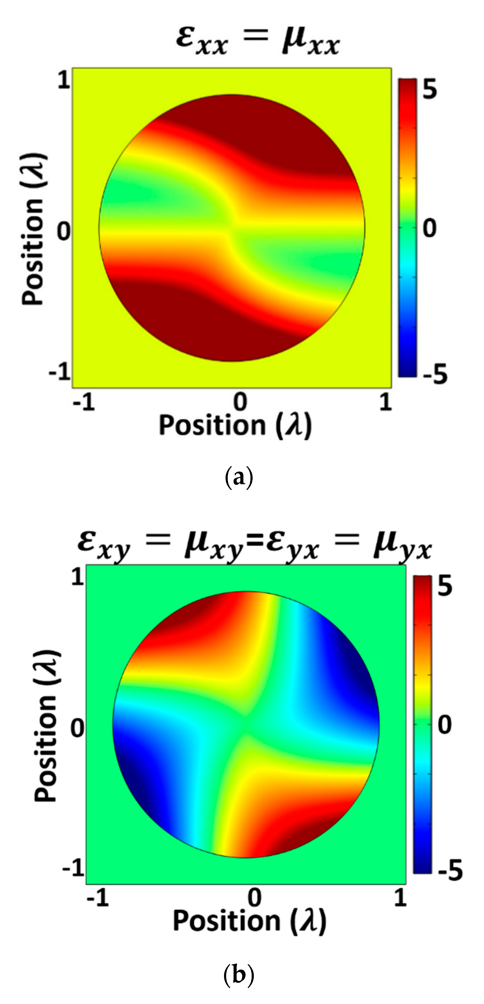
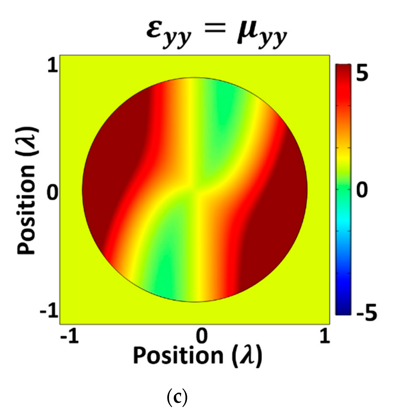
20]. It is desired that the “pinwheel” shape antenna has a radiation field pattern similar to the dipole antenna, but its impedance and complex power will be preserved under the “pinwheel” transformations. Similarly, the material parameters can be obtained using (2), (4), and (5) as:
Equation (7) results in anisotropic and inhomogeneous permittivity and permeability tensors. Both electromagnetic parameters
and
have the same behavior, as shown in
Figure 2. It is also worth noting that the results lead to a perfect impedance matching with no reflection at the boundaries of the material region and free space. Such an anisotropic and inhomogeneous transformation medium can be realized by discrete metamaterials and structures such as periodic split ring resonators (SRRs) [
21].
Now, the material parameters from (7) and the transformed current from (6) were used to transform each element of the “reference array” into a “pinwheel” antenna element and realize the linearly transformed “pinwheel” antenna array, as shown in
Figure 1b. The dimensions and edge-to-edge distance between the array elements were kept the same in the transformed “pinwheel” antenna array as in the “reference” linear dipole array. It is worth noting that while designing the “pinwheel” antenna elements of the transformed array, the current distribution from (5) and the material parameters from (7) were translated as the coordinates were no longer at the origin. The coordinates of the “pinwheel” elements changed along the y-direction, and the coordinates remained constant in the x-direction (
).
3. Full-Wave Simulation Results and Discussion
To demonstrate the accuracy of the proposed theoretical model of the linear “pinwheel” antenna array, numerical simulations were performed in the commercially available finite-element analysis (FEA) software COMSOL Multi- physics
®. The transformation electromagnetics/optics (TE/TO) approach often results in anisotropic, non-homogeneous, and complex material parameters in matrix form. COMSOL Multiphysics has the capability to validate works related to transformation electromagnetics/optics, as it allows the specification of material anisotropy and continuous inhomogeneity, as found in [
13,
14,
15,
16,
17,
18]. The work presented here adopts the validation process presented in [
13,
14,
15,
16,
17,
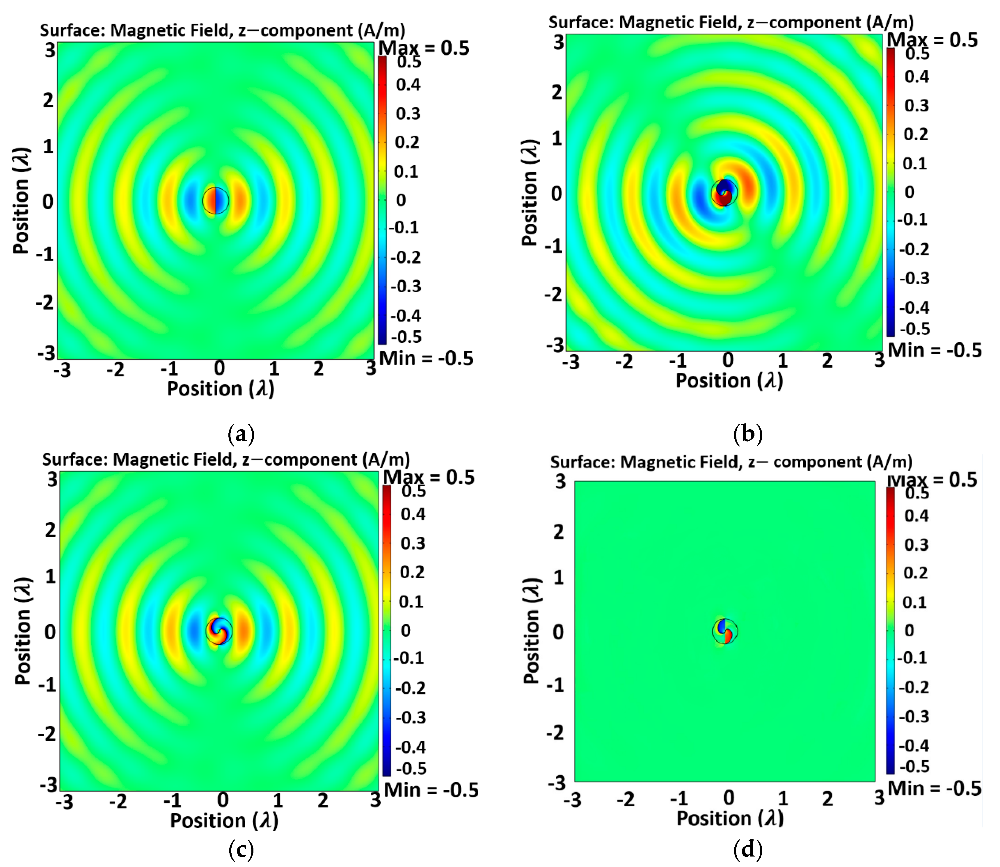
18] by comparing theory with COMSOL results. In the “pinwheel” transformation, along with the transformed current source from Equation (6) and transformed material parameters from Equation (7), the “pinwheel” shaped antenna geometry is also a function of the proposed transformation. COMSOL Multiphysics has a unique functionality, which allows the definition of the complex “pinwheel” shaped geometry and material, as opposed to other commercially available full-wave tools. First, the single element, as shown in
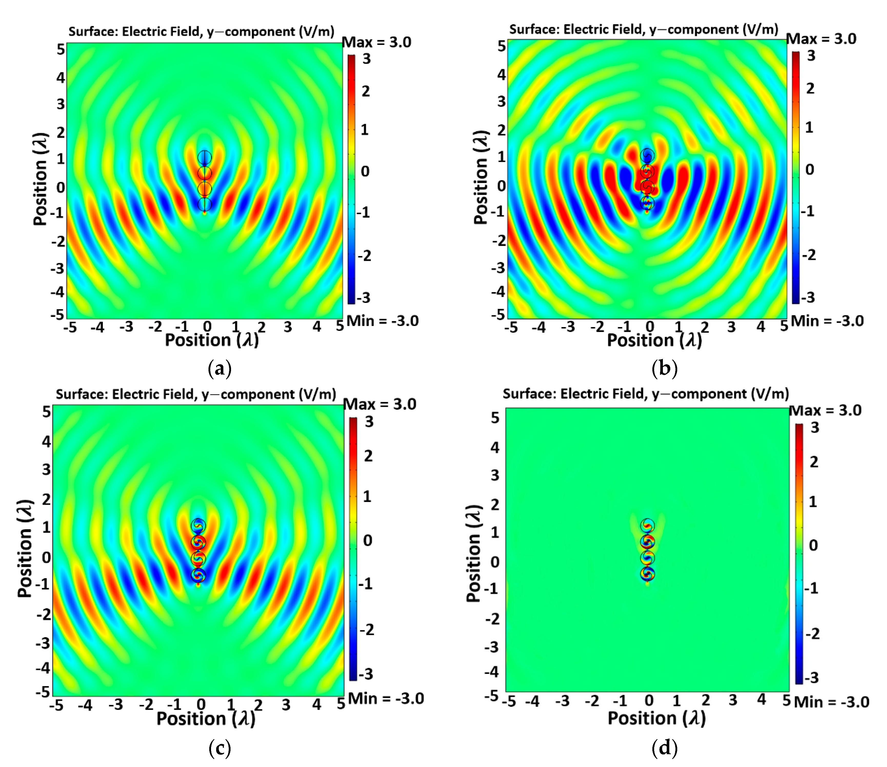
Figure 1a, was simulated to verify the transformed current from (6) and the transformed media from (7). Simulation results from a half-wave (
dipole antenna in free-space are shown in
Figure 3a. A frequency of 10 GHz was chosen. If the dipole is twisted by an angle of 180° without proper material compensation from (7), the field pattern changes significantly, which is demonstrated in
Figure 3b. The field pattern is recovered outside the transformation media once the correct material is used from (7), which is illustrated in
Figure 3c. The fields from the dipole in
Figure 3a and the transformed “pinwheel” antenna in
Figure 3c outside the material shell are the same. This is emphasized in
Figure 3d, which shows almost no field distribution outside the transformation media when the difference between the two fields is taken. This also confirms that the current distribution in (1) is conserved under the “pinwheel” coordinate transformation in (6).
It is also important to note that the meshing method used for the simulation is free-triangular. The mesh used in the simulation has over 45,000 elements to ensure convergence and accurate results and also to effectively approximate the continuous profiles given by Equation (7). The minimum meshing element quality is 0.2694, the average element quality is 0.9154, and the element area ratio is 0.001049. The total mesh vertices are 22,555.
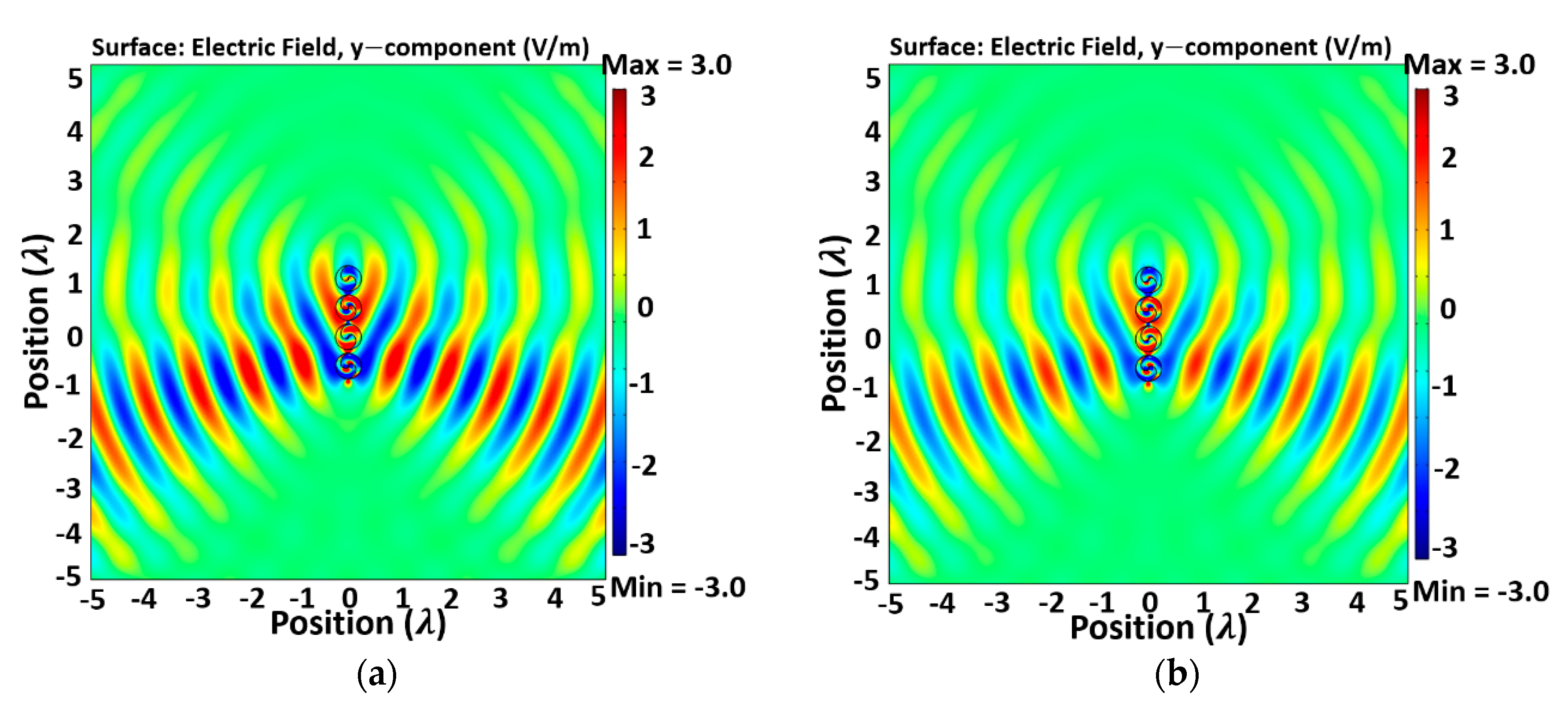
Figure 4 demonstrates the verification of the proposed transformed antenna array design.
Figure 4a represents the electric field of the reference dipole antenna array as described in
Figure 1b. The phase difference between any two adjacent elements is set to 90° to scan the beam at an angle
22.5°. For a fair comparison,
Figure 4b demonstrates the electric field distribution radiated by the transformed “pinwheel” linear array, where the “pinwheel” antenna elements are not enclosed by the material parameters defined by (7). The fields in
Figure 4b are significantly different from that radiated by the original linear dipole array in
Figure 4a.
Figure 4c shows the electric field distribution radiated by the proposed “pinwheel” antenna array, where each antenna element is enclosed by the transformation medium from (7) and the current distribution is given by (6). The phase difference between any two adjacent “pinwheel” elements is kept the same as the “reference array”. The simulation results show that the radiated fields by the transformed “pinwheel” linear array (
Figure 4c) and the reference dipole array (
Figure 4a) are virtually identical. To further verify the design, the difference between the two fields is shown in
Figure 4d, which clearly shows that there is almost zero field distribution around the array after subtraction of field in
Figure 4c from the field in
Figure 4a.
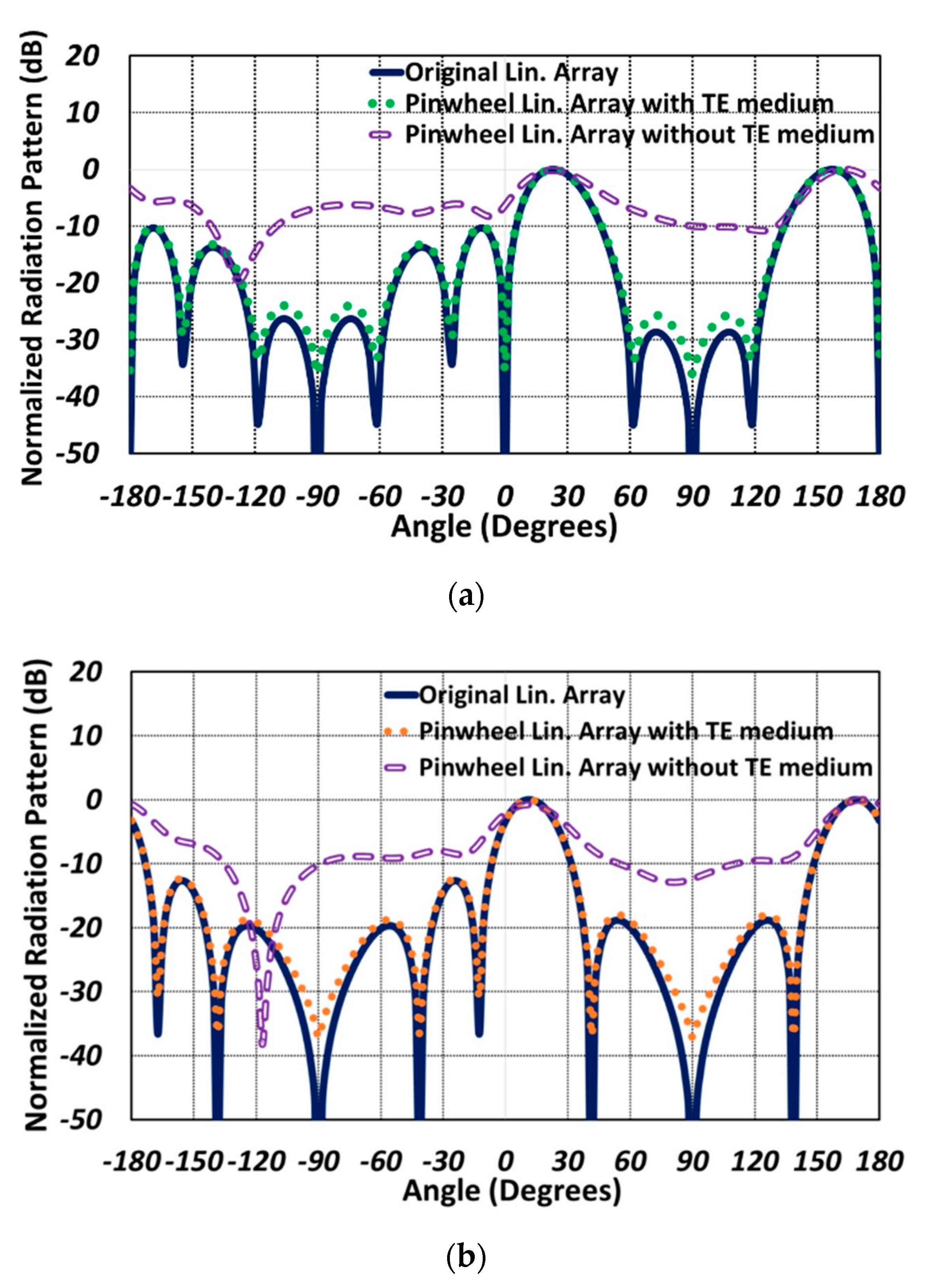
Furthermore, the far-fields of the “reference dipole array” and the transformed “pinwheel” array are simulated and illustrated in
Figure 5. As shown in
Figure 5, the normalized radiation patterns of the reference array and the transformed “pinwheel” array are almost the same when each element of the “pinwheel” array is enclosed by the transformed medium, but are different when the elements are not compensated with proper material parameters.
Figure 5b shows the normalized radiation pattern at a scan angle
11.25°. The phase difference between any two adjacent elements is set to 45°, as set in the original dipole array.
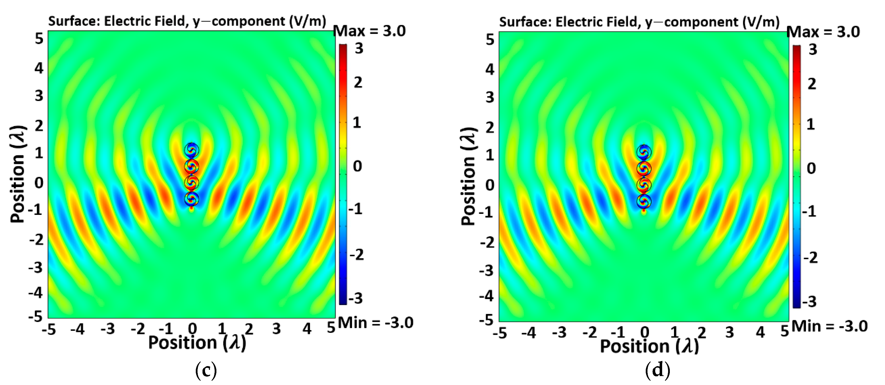
Metamaterials are foremost candidates for realizing the non-homogeneous and anisotropic material parameters from (7) to implement the proposed “pinwheel’ array. In metamaterial realizations, losses may be a restraining factor in practical implementation [
16,
17,
18]. Considering the losses in practical materials, numerical simulations were performed introducing different values of loss tangents (
) for a scan angle
22.5°, as shown in
Figure 6. Loss was incorporated in the simulations by replacing
with
[
17,
18,
22]. Similar modifications were made to other material tensor parameters.
Figure 6 shows that the antenna performance degrades with the increase of loss factor. With the loss tangent reduced to only 0.1, the effect of loss is almost unnoticeable. No significant differences were observed in the range
. With loss tangents of 0.1, 03, and 0.5, the lossy material is still effective, excepting for the reduction of the electric field magnitude.


 ,
, 