Article

Adaptive Deterministic Vibration Control of a Piezo-Actuated Active–Passive Isolation Structure

School of Mechatronic Engineering and Automation, Shanghai University, Shanghai 200444, China
*
Authors to whom correspondence should be addressed.
Appl. Sci. 2021, 11(8), 3338; https://doi.org/10.3390/app11083338
Submission received: 8 March 2021 / Revised: 1 April 2021 / Accepted: 5 April 2021 / Published: 8 April 2021

Abstract

:
With the improvement of the performance of optical equipment carried by on-orbit spacecraft, the requirements of vibration isolation are increasing. Passive isolation platforms are widely used, but the ability to suppress the low-frequency deterministic vibration disturbance is limited, especially near the system’s natural frequency. Therefore, an active vibration control strategy is proposed to improve passive isolation performance. In this paper, a Youla parameterized adaptive active vibration control system is introduced to improve the isolation performance of a piezo-actuated active–passive isolation structure. A linear quadratic Gaussian (LQG) central controller is first designed to shape the band-limited local loop of the closed-loop system. Then, the central controller is augmented into a Youla parameterized adaptive regulator with the recursive least square adaptive algorithm, and the Youla parameters (Q parameters) can be adjusted online to the desired value to suppress the unknown and time-varying multifrequency deterministic vibration disturbance. In the experiment, the residual vibration with respect to the combination of multiple frequencies is effectively suppressed by more than 20 dB on average, and a quick response time of less than 0.3 s is achieved when the deterministic residual vibration changes suddenly over time. The experimental results illustrate that the proposed adaptive active vibration control system can effectively suppress the low-frequency deterministic residual vibration.

1. Introduction

With the improvement of the performance of optical equipment carried by on-orbit spacecraft, the requirement of vibration isolation on the space instrument platform is increasing in the space microgravity environment. For example, the vibration caused by the mass imbalance of the momentum wheels should be suppressed to a micrometers level to ensure the image quality of satellites [1]. The main vibration disturbance of on-orbit spacecraft is often caused by reaction/momentum wheel assemblies [2]. Additionally, with the introduction of the large flexible appendage systems of spacecraft with a cantilever structure, such as solar panel, communication antenna, and space robotic arm, the resonant mode may be excited during the operation of the flexible system, and the deterministic vibration disturbance will be formed [3]. Particularly, the static imbalance, dynamic imbalance, and bearing imperfection of assemblies will excite a large amplitude deterministic vibration disturbance [4]. These deterministic vibration disturbances will have multifrequency and time-varying characteristics, mainly distributed in the low-frequency range below 150 Hz [5], and even ultralight and large size flexible structures may produce vibration around 10 Hz [6].
To suppress the vibration disturbance from the base of the optical equipment placement platform, the passive isolation platform is widely used to carry the precision optical equipment on spacecraft [2]. With the higher performance requirement of vibration isolation, the limitations of the passive isolation platform have made the active vibration control system more attractive [7]. One of the limitations that cannot be ignored is that the low-frequency deterministic vibration disturbance is not sufficiently isolated, and especially near the system natural frequency of the isolation system, the disturbance may be amplified [8]. Moreover, there is an unavoidable design contradiction between the structural bearing capability and low-frequency vibration isolation. Therefore, some active vibration control strategies are proposed to improve the low-frequency vibration isolation performance.
Among many vibration isolation platforms on spacecraft, the Stewart-like parallel kinematic platform not only has advantages of stability, high precision, and high payload-bearing capability, but also can provide support for different active control methods, and the related vibration isolation systems have been discussed in reference [9]. The key to the isolation performance of the Stewart-like platform is the design of the single support axis vibration isolation system [10]. Therefore, this paper will focus on the design of an adaptive active control system for the single-axis isolation structure, which can be used to suppress the low-frequency unknown deterministic residual vibration with multifrequency and time-varying characteristics. Generally, the main methods of active vibration control (AVC) are feedforward and feedback control.
Feedforward control directly uses the reference signal of the vibration source to eliminate the residual vibration. Elliott et al. discussed the characteristics of feedforward and feedback systems for the active vibration control, and pointed out that the feedforward system relies on the existence of some prior knowledge of the vibration disturbance to be controlled, and the prior knowledge is contained in a reference signal that drives the secondary source through the controller [11]. Liu et al. present a novel feedforward control algorithm with the orthogonal pair-wise reference frequency regulator, and the multiple-frequency vibration was dramatically suppressed with an improved convergence rate [12]. An adaptive feedforward vibration control system with variable step size is developed in Reference [13], which was successfully implemented to suppress the vibration of a kind of thin-walled structure. As long as the frequency of the reference signal obtained through the sensor is accurate enough, the feedforward control can realize the effective compensation of residual vibration. However, in some cases, the reference signal of the vibration source is difficult to obtain accurately, which will degrade the feedforward control performance. Feedback control only needs to detect the residual vibration of the controlled object, without paying attention to the source of vibration. Reference [14] presented an investigation on the performance of active vibration control of the rib-stiffened plate by using only residual velocity feedback signal. An adaptive feedback control system is designed for the unknown vibration disturbance suppression of a lathe system in Reference [15], in which an adaptive algorithm is introduced to adjust the feedback controller in real time according to the unknown residual acceleration feedback signal. Besides, compared with feedback control, feedforward control will use more sensors that will not be conducive to the light weight and reliability of the vibration isolation system. Therefore, feedback control should be considered.
The control approaches of lead/lag, H, and linear quadratic Gaussian (LQG) are common feedback controls for AVC systems. Thenozhi and Yu applied the proportion integral differential(PID) control approach to active vibration control of building structures and analyzed the system stability [16]. Montazeri et al. designed an optimal robust minimax LQG controller by the proper choice of the weight parameters and applied it to the vibration control of flexible beams [17]. Song et al. developed an H controller to suppress frequency-varying vibration disturbances of the floating raft isolation system [18]. Wu studied a simultaneous mixed LQR/H control approach based on the vibration suppression of quarter-car active suspension systems [19]. The feedback controller mentioned above reduces the sensitivity function of the desired frequency range by obtaining a high open-loop gain, and then realizes the vibration suppression in the corresponding frequency range. However, Bode’s sensitivity integral theorem indicates that the sensitivity function S ( j w ) should satisfy 0 ln | S ( j w ) |   d w = 0 for the stable plant, and the area of sensitivity reduction ( ln | S | negative) should equal the area of sensitivity increase ( ln | S | positive) [20]. For the active vibration control system, the concrete manifestation is that the vibration will be inevitably amplified outside the frequency range where the vibration is expected to be suppressed, which is also known as the “waterbed effect”. In addition to this important limitation, if the open-loop gain is too high, it will also reduce the phase margin and decrease the robustness. Therefore, these controllers cannot completely suppress the deterministic vibration disturbance, especially with multifrequency and time-varying characteristics.
The feedback control based on the disturbance observer (DOB) [21] and the internal model principle (IMP) [22] is an effective solution for the suppression of deterministic vibration disturbances. The related feedback control methods based on the DOB were compared and summarized in Reference [23], and the design of the DOB was comprehensively analyzed. The reference indicated that the key to the design of the feedback control system based on the DOB is the selection of its low-pass filter with a proper cutoff frequency, which is related to the external disturbance’s property. When the disturbance changes in a wide range due to time-varying, the disturbance suppression effect is limited. Cai et al. designed a zero-phase odd repetitive controller that was used for the suppression of deterministic vibration in a magnetically suspended centrifugal compressor based on IMP [24]. The repetitive control system is to implant the dynamic model of external interference signal into the closed-loop system to realize the suppression of known deterministic vibration disturbance. It can be seen that when the disturbance is time-varying, the dynamic model of disturbance will also change, and it will be difficult for the original repetitive control system to suppress the new disturbance. Recently, a novel compensator capable of minimum-time performance of an in-plane maneuver with zero residual vibration and zero residual vibration-derivative at the end of the maneuver is proposed in Reference [6]. The novel compensator has a whiplash nature of first commanding maneuver states in the opposite direction of the desired end state to achieve the minimum-time performance of the robot manipulation. However, the control performance subjected to the external unknown vibration disturbances needs to be further evaluated.
Reference [25] summarized the latest development and application of the Youla parameterization method, in which the parameterization process of the control system is analyzed in detail. The direct or indirect adaptive disturbance suppression algorithm based on Youla parameterization was compared and analyzed in Reference [26], which indicated that the parameterization of the controller is beneficial to the combination of adaptive algorithm. It can be seen that the model of vibration disturbances can be inserted in the controller by the Youla parameterization method; by augmenting the free parameter Q ∈ RH, the parameterized controller is designed as a global stable controller that can fit almost any dimension internal model of the multifrequency vibration disturbance. The adaptive algorithm can be introduced to adjust the free parameter Q of the resulting parameterized controller online according to the vibration disturbance, so the unknown or time-varying deterministic vibration disturbance will be gradually eliminated. Ben Amara et al. designed a Youla parameterized adaptive controller to realize the elimination of the sinusoidal noise disturbance in an acoustic duct [27]. Wu et al. modified the Youla parameterized controller with an adaptive notch filter to compensate for the airflow disturbance and vibration of the disk in the data storage system [28]. However, in this paper, the suppression of the low-frequency deterministic vibration and the band-limited local loop shaping of the closed-loop system near the system’s natural frequency will be considered simultaneously. Therefore, an observer-based state feedback central controller with an augmented Q parameter will be introduced. The central controller will be designed to shape the band-limited local loop of the closed-loop system, and the augmented Youla (Q) parameterized controller will be adjusted online to eliminate the low-frequency deterministic vibration.
The Youla (Q) parameterized adaptive active vibration controller is designed in two steps. The inner-loop central controller is a linear quadratic Gaussian (LQG) controller that is used to shape the band-limited local loop of the closed-loop system near the system’s natural frequency. Then, by augmenting the LQG controller, the Youla parameterized adaptive controller with the recursive least square (RLS) adaptive algorithm is formulated to completely suppress the deterministic residual vibration. The proposed adaptive active vibration control method is applied to the piezo-actuated active–passive isolation structure. The experimental results illustrate that the proposed adaptive active vibration control method can effectively optimize the vibration transmissibility curve near the system’s natural frequency and suppress the unknown and time-varying low-frequency deterministic residual vibration.
This paper is organized as follows. The piezo-actuated active–passive isolation structure is analyzed in Section 2. Section 3 is devoted to the design of the active vibration controller which is an adaptive regulator with the central controller and adjustable free Q parameter. The proposed active vibration controller is applied to eliminate the vibration of the piezo-actuated active–passive isolation structure and the experiment results are evaluated in Section 4. Section 5 concludes the paper with a summary.

2. Analysis of a Piezo-Actuated Active–Passive Isolation Structure

2.1. Piezo-Actuated Active–Passive Isolation Structure Layout

As shown in Figure 1, the piezo-actuated active–passive isolation structure is an improvement based on the stiff active damping structure [29], which can be applied as the support axes of the multi-DOF Stewart platform with a cubic hexapod configuration [30]. The payload plate and base plate of the Stewart platform are connected with the isolation structures via flexible joints which are used to avoid the influence of backlash and friction caused by the conventional joints. The piezoelectric actuator is used to execute the control output and the force sensor is adopted for the detection of residual vibration signal e, which consists of a local force feedback system for active vibration control. The actuator and sensor are connected through a passive unit which is designed by a metal spring with a special structure to isolate the vibration source disturbance. The disturbance generated by the vibration source is transmitted to the force sensor through the passive unit, which leads to the residual vibration, and the primary path is formed from the vibration source to the force sensor. Then, the piezoelectric actuator actively compensates for the residual vibration feedback from the force sensor to form the secondary path.
The piezo-actuated active–passive isolation structure can be equivalent to a single degree of freedom (DOF) dynamic model, then the dynamic model of the multi-DOF Stewart platform with the cubic hexapod configuration can be derived via the topological transformation of the Jacobi matrix. The cubic hexapod configuration is that six single supporting axes form a cube, and the two adjacent axes are orthogonal in space. Since the displacement of each active strut caused by microvibration is very small and the coupling between two adjacent axes is also small, the Jacobi matrix can be assumed to be invariant [10]. Meanwhile, the cubic hexapod configuration can realize the decoupling of geometric configuration and minimize the cross-coupling force effect of each axis. It can be seen that when the vibration isolation system is subjected to microvibration, the dynamics of the multi-DOF Stewart platform can be decoupled into six approximately identical independent single-DOF systems. Therefore, in order to control the vibration of the multi-DOF Stewart platform, in this paper, an adaptive active vibration controller is proposed for the single-DOF piezo-actuated active–passive isolation structure.
The piezo-actuated active–passive isolation structure occupies little space, which is beneficial to the vibration isolation of the aerospace field. However, the structure consists of the flexible rod, the special-shaping spring, and the piezoelectric actuator in series; the dynamic behavior of each part is superimposed, which will make the isolation structure form a complex high-order dynamic system with multiple zeros and poles. Moreover, the deterministic vibration disturbance of on-orbit spacecraft has a time-varying characteristic. Therefore, an adaptive active vibration control system will be introduced based on the Youla parameterization approach.

2.2. Adaptive Active Vibration Control System Formulation

As shown in Figure 2, an adaptive active vibration control system is designed and applied to the piezo-actuated active–passive isolation structure. The deterministic residual vibration signal wd of the primary path causes the error signal e which characterizes the vibration of the payload, and the control signal u of the adaptive regulator drives the actuator to act on the second path to compensate the wd actively.
The proposed adaptive active vibration control method does not require the model of the vibration source signal and the primary path so that the above system is simplified as shown in Figure 3. The K(Q) represents the controller corresponding to the shadow region in Figure 2 and the P represents the second path. The error signal e is used as the feedback signal, and the control signal u acts directly on the P, then the system can be further simplified.
The discrete-time system model G represented in state space can be written as:
G   :   { x ( k + 1 ) = A x ( k ) + B u ( k ) , x ( 0 ) = x 0 e ( k ) = C e x ( k ) + w d ( k ) + v ( k )
where v ( k ) is the measurement noise, and the unknown multifrequency or time-varying deterministic residual vibration signal wd can be described as:
w d ( k )   =   = 1 n A ( k ) cos ( ω ( k ) k   +   ϕ ( k ) )
with unknown or time-varying amplitude A , frequency ω and phase ϕ , and = 1 n .

3. Design of Adaptive Active Vibration Controller

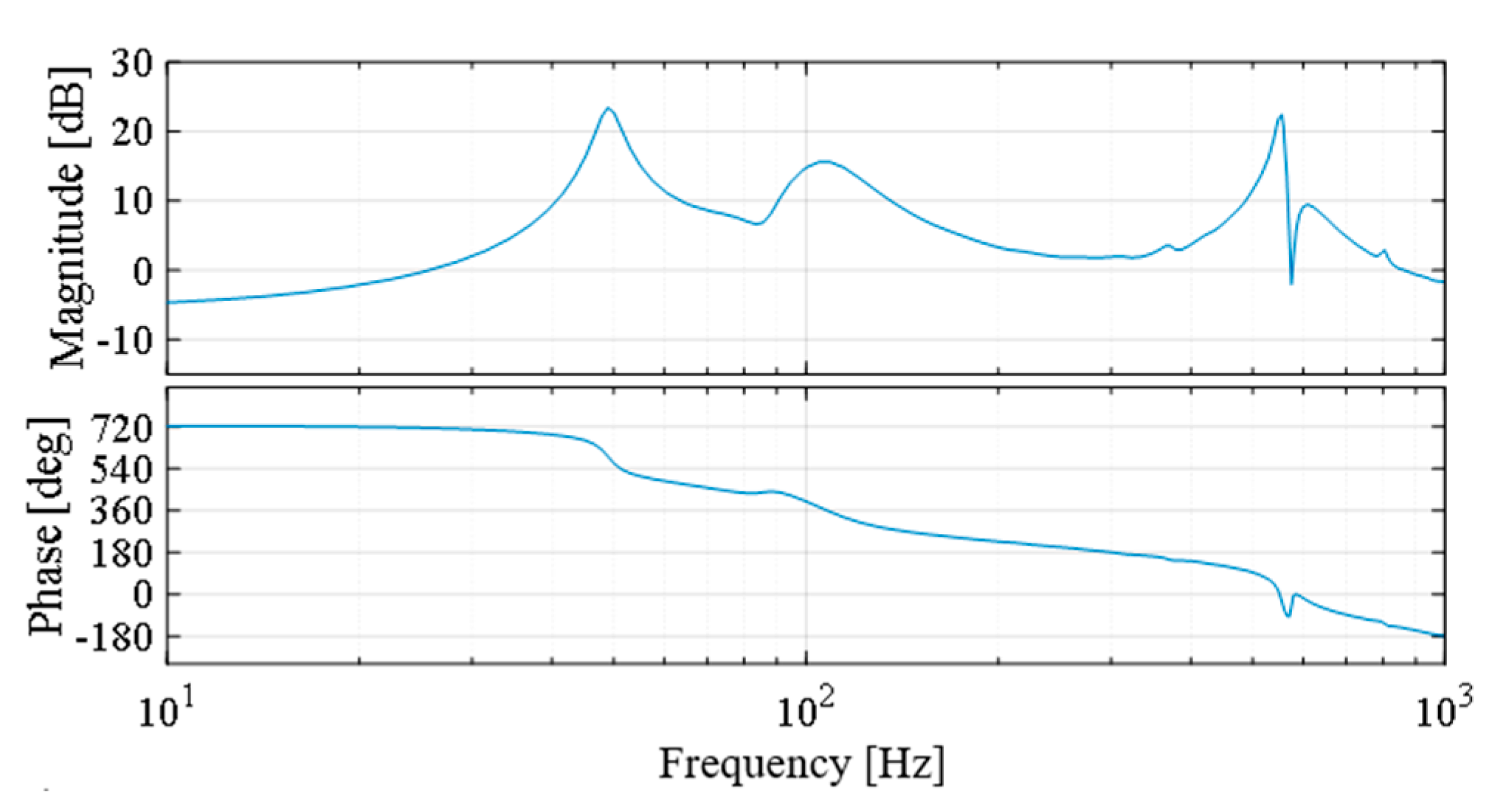
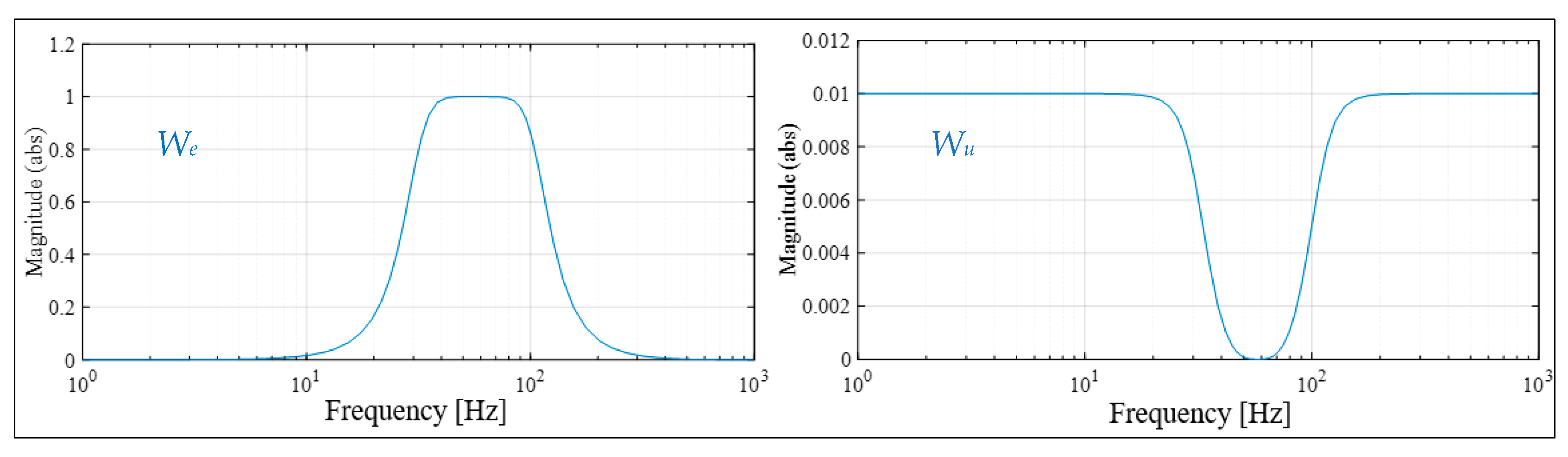
3.1. Design of the Inner-Loop Central Controller

As shown in Figure 3, the feedback controller K without the Q parameter is the inner-loop central controller. The controller K is designed as an LQG controller to shape the band-limited local loop of the closed-loop system. Let w b ( k ) represent the band-limited signal near the system natural frequency, thus the reference model can be expressed under the white noise signal w n ( k ) as:
Σ b   :   { x b ( k   +   1 )   =   A b x b ( k )   +   B b w n ( k ) , x b ( 0 )   =   x b , 0 w b ( k )   =   C b x b ( k )
Correspondingly, system (1) can be extended to
Σ   :   { x ˜ ( k   +   1 )   =   A ˜ x ˜ ( k )   +   B ˜ u ( k )   +   E ˜ x w ( k ) , x ˜ ( 0 )   =   x ˜ 0 e ( k )   =   C ˜ e x ˜ ( k )   +   E ˜ e w ( k )   +   v ( k )
where x ˜ ( k )   =   [ x ( k ) x b ( k ) ] , A ˜   =   [ A 0 0 A b ] , B ˜   =   [ B 0 ] , E ˜ x   =   [ 0 0 0 B b ] , C ˜ e   =   [ C e C b ] , E ˜ e   =   [ 1 0 ] , w   =   [ w d ( k ) w n ( k ) ] T .
The observer-based state feedback controller for the system (4) can be given as:
K : { x ^ ( k + 1 ) = A ˜ x ^ ( k ) + B ˜ u ( k ) + L ( y ^ ( k ) y ( k ) ) , x ^ ( 0 ) = x ^ 0 u ( k ) = F x ^ ( k ) ,
where x ^ ( k ) is an estimate of the state vector x ˜ ( k ) , F represents the state feedback gain, and L represents the observer gain.
The optimal state feedback gain F is obtained according to the quadratic optimal control method, and the observer gain L is determined by the Kalman filter method. Then the band-limited local loop of the closed-loop system will be shaped by selecting the appropriate weight parameters of the LQG controller.

3.2. Youla Parameterization of the Inner-Loop Central Controller

The central controller cannot completely suppress the low-frequency deterministic residual vibration, especially with multifrequency and time-varying characteristics. Then, the Youla parameterized controller is formulated by augmenting the central controller with the Q parameter based on the internal model principle (IMP), and the adaptive algorithm is developed to online tune the free Q parameter according to the variable residual vibration.
The Youla parameterization of the controller consists of the interconnection of two blocks: a fixed block J and a stable system Q that can be chosen as desired [31].
The J block can be written as:
J : { x ^ ( k + 1 ) = ( A ˜ + B ˜ F + L C ˜ y ) x ^ ( k ) L y ( k ) + B ˜ y Q ( k ) x ^ ( 0 ) = x ^ 0 u ( k ) = F x ^ ( k ) + y Q ( k ) y ( k ) y ^ ( k ) = y ( k ) C ˜ y x ^ ( k ) ,
The Q block can be written as:
Q : { x Q ( k + 1 ) = A Q x Q ( k ) + B Q ( y ( k ) y ^ ( k ) ) , x Q ( 0 ) = x Q , 0 y Q ( k ) = C Q x Q ( k )
Then, the Youla parameterized controller K(Q) consists of two interconnected blocks J and Q as shown in Figure 4.
To realize the design of the adaptive regulator, the augmented plant G and the controller J are integrated into T as shown in Figure 5.
Therefore, T can be represented as follows:
[ e ( k ) y ( k ) y ^ ( k ) ] = T [ w ( k ) y Q ( k ) ]
where
T   = [ T 11 T 12 T 21 T 22 ]
T 11 : [ A ˜ + B ˜ 1 F B ˜ F E ˜ x 0 A ˜ + L C ˜ e E ˜ x L E ˜ e C ˜ e 0 E ˜ e ]
T 12 : [ A ˜ + B ˜ F B ˜ C ˜ e 0 ]
T 21 : [ A ˜ + L C ˜ e E ˜ x L E ˜ e C ˜ e E ˜ e ]
T 22 : [ A ˜ + L C ˜ e 0 C ˜ e 0 ]
Let W ( z ) and E ( z ) denote the Z transform of the disturbance input w and the system error e. The closed-loop transfer function from w to e can be obtained by linear fractional transformation as follows:
E ( z ) = [ T 11 ( z ) + T 12 ( z ) Q ( z ) T 21 ( z ) ] W ( z )
To adjust the adaptive regulator for multifrequency deterministic residual vibration and take into account the stability requirement of the closed-loop system, the Q parameter is considered as:
Q ( z ) = q = 1 n q θ q z 1 q F ( z )
where F ( z ) = b 1 z m 1 + b m z m + a 1 z m 1 + a m is a stable weighting function used to adjust the dynamic properties of Q ( z ) . By properly choosing F ( z ) , the robustness of the closed-loop system can be improved.
According to the internal model principle, let θ = [ θ 1 θ 2 θ n q 1 θ n q ] T be the free parameter, then the attenuation conditions of the deterministic residual vibration can be written as follows [32]:
A θ θ + B θ = 0
where
A θ = [ V 1 , r e ( p 1 ) V n q , r e ( p 1 ) V 1 , i m ( p 1 ) V n q , i m ( p 1 ) V 1 , r e ( p k 0 ) V n q , r e ( p k 0 ) V 1 , i m ( p k 0 ) V n q , i m ( p k 0 ) ]
B θ = [ V 0 , r e ( p 1 ) V 0 , i m ( p 1 ) V 0 , r e ( p k 0 ) V 0 , i m ( p k 0 ) ]
where A θ R n p × n q , B θ R n p × 1 , n p = 2 k 0 , k 0 is the number of pairs of complex conjugate poles of the multifrequency deterministic disturbances. V 1 , r e ( p j ) and V 1 , i m ( p j ) denote the real and imaginary parts of the functions V 1 ( p j ) , respectively. V 0 , r e ( p j ) and V 0 , i m ( p j ) denote the real and imaginary parts of the functions V 0 ( p j ) , respectively, j = 1 , , k 0 . p j denote the poles of disturbance W ( z ) , and n q k 0 . V 1 ( z ) and V 0 ( z ) are given by V 1 ( z ) = T 12 ( z ) z 1 q F ( z ) T 21 ( z ) and V 0 ( z ) = T 11 ( z ) .
According to the condition (16), the corresponding θ can be found to eliminate multifrequency deterministic residual vibration. However, it cannot ignore the fact that the deterministic residual vibration also has unknown or time-varying characteristics, so that the adaptive algorithm is developed to tune θ online and converges to the target parameter, then the system achieves the elimination of the unknown multifrequency or time-varying deterministic residual vibration.

3.3. Adaptation Algorithm

Let z l denote the l time step delay operator, based on (14), then the system error e ( k ) is given by
e ( k ) = [ T 11 ( z 1 ) + T 12 ( z 1 ) Q k T 21 ( z 1 ) ] w ( k )
where Q k = Q ¯ k F ( z 1 ) and Q ¯ k = q = 1 n q θ q ( k 1 ) z 1 q .
According to (8), let
r ( k ) = T 21 ( z 1 ) w ( k )
Then, (19) can be represented as follows:
e ( k ) = T 11 ( z 1 ) w ( k ) + T 12 ( z 1 ) Q ¯ k F ( z 1 ) r ( k )
Let θ * be a constant parameter satisfying the interpolation condition (16) and Q * be the Q parameter that results from θ * . The corresponding system error can be then written as:
e * ( k ) = T 11 ( z 1 ) w ( k ) + Q ¯ * T 12 ( z 1 ) F ( z 1 ) r ( k )
at the same time lim k e * ( k ) = 0 .
Define a nominal system error:
e ˜ ( k ) = T 11 ( z 1 ) w ( k ) + Q ¯ k T 12 ( z 1 ) F ( z 1 ) r ( k )
Then, combined with (22), we have that:
e ˜ ( k ) = ϕ T ( k ) θ ˜ ( k 1 ) + e * ( k )
where
ϕ ( k ) = [ υ ( k ) υ ( k n q + 1 ) ] T
θ ˜ ( k ) = [ ( θ , 1 θ 1 ( k ) ) ( θ , n q θ n q ( k ) ) ] T
υ ( k ) = T 12 ( z 1 ) F ( z 1 ) r ( k )
Based on (24) and lim k e * ( k ) = 0 , it is not difficult to find that the e ˜ ( k ) can be obtained by r(k), which can be calculated at each step through the J block based on the measurement value of system output y(k), therefore, the e ˜ ( k ) is no longer restricted by the unknown w ( k ) .
According to (24), the estimated θ ^ of θ can be performed using the recursive least squares algorithm (RLS) with a forgetting factor λ ( k ) as the following expressions:
θ ^ ( k ) = θ ^ ( k 1 ) + P ( k 1 ) ϕ ( k ) 1 + ϕ T ( k ) P ( k 1 ) ϕ ( k ) e ˜ ( k )
P ( k ) = 1 λ ( k ) [ P ( k 1 ) P ( k 1 ) ϕ ( k ) ϕ T ( k ) P ( k 1 ) 1 + ϕ T ( k ) P ( k 1 ) ϕ ( k ) ]
with the initial values of θ ^ ( 0 ) = 0 , P ( 0 ) > 0 , and λ ( k ) which can be valued in 0.95~1 for the linear time-invariant system.
Based on lim k e * ( k ) = 0 , it should be noted that the e * ( k ) does not influence the convergence result of (28) and (29). At the same time, consider F ( z 1 ) and T 12 ( z 1 ) are all stable, we can have that the ϕ ( k ) is bounded under the persistent excitation of the bounded vibration signal w ( k ) based on (20), (25), and (27). Therefore, the sufficient condition of the stability of the algorithm (28) and (29) is satisfied according to the strictly positive real condition [33], and we can have lim k θ ^ ( k ) = θ * . The θ * corresponding to the w ( k ) satisfies the interpolation condition (16), then the closed-loop system achieves the elimination of the unknown multifrequency or time-varying deterministic residual vibration.

4. Experiment

4.1. Description of the Experimental System

As shown in Figure 6, a suspension installation is adopted such that the base platform and payload platform are connected to a hanging rope to simulate the space microgravity environment, and the vibration generator is connected to the base platform. The vibration disturbance signal is generated by PC-based MATLAB/Simulink Real-Time Windows Target and drives the vibration generator through the port AO-2 of the NI PXI6363 AD/DA card, and the system primary path is formed from the vibration generator to the force sensor. According to the force sensor feedback signal of the port AI-1, the active control signal of the adaptive regulator is implemented through the port AO-1 to drive the piezoelectric actuator, and the second path is formed from the piezoelectric actuator to the force sensor.
A real-time active vibration control experimental system is established as shown in Figure 7. A charge amplifier (model BZ2105) is responsible for charge amplification of the force sensor (model KF24), and a drive power (model E00.A6) is used to drive the piezoelectric actuator (model P06.X60AK). A vibration generator (model JZ-2) is driven by a power amplifier (model GF-50) and performs the excitation signal which is generated from the port AO-2.
The vibration characteristics and stability of the flexible structure can be analyzed by establishing the dynamic differential equation and the corresponding boundary conditions [34]. For example, a new way to develop the stability model for the straight turning of a cylindrical flexible workpiece using the Chebyshev collocation method is presented recently, in which the model is described by delay differential equations [35]. Considering that the piezo-actuated active–passive vibration isolation system in this paper is a dynamic problem of multibody flexible system, the system identification method is used to obtain the high-order dynamic model with multiple zeros and poles.
The transfer function of the system’s secondary path will be obtained by the system identification method; it is used to design the adaptive active vibration controller. The sampling frequency is selected as 2000 Hz and the excitation signal of the piezoelectric actuator is the chirp signal with a frequency from 1 to 1000 Hz. Then, according to the input and output signal of the secondary path, the transfer function is identified as a fifty-order model. The Bode diagram of the system’s secondary path is shown in Figure 8.

4.2. Test Results of H Control

In the following, the well-known H optimal feedback control approach is first designed and evaluated. The H control algorithm for the suppression of external disturbance can be realized by selecting the appropriate weighting functions [18]. In this paper, the H controller is designed using the augw and hinfsyn functions in MATLAB based on the identified model. Considering the deterministic vibration disturbance with frequencies [35-70-105] Hz, the weighting functions We on the output e and Wu on the control input u are selected as:
W e = 0.001567 z 6 0.004701 z 4 + 0.004701 z 2 0.001567 z 6 5.409 z 5 + 12.28 z 4 15 z 3 + 10.38 z 2 3.863 z + 0.6041
W u = 0.007772 z 6 0.04587 z 5 + 0.1136 z 4 0.1509 z 3 + 0.1136 z 2 0.04587 z + 0.007772 z 6 5.409 z 5 + 12.28 z 4 15 z 3 + 10.38 z 2 3.863 z + 0.6041
The corresponding Bode plots of the two weight functions are shown in Figure 9.
Figure 10 illustrates the system time-domain response of the deterministic vibration disturbance with frequencies [35-70-105] Hz, and Figure 11 illustrates the corresponding power spectral density(PSD) estimate. It can be seen that the H active vibration control system cannot effectively suppress the deterministic vibration disturbance at the frequencies [35-70-105] Hz and only a vibration suppression around 10 dB on average is achieved. Although the smaller H norm can be obtained by decreasing the gain of the weight function Wu, the space for the control performance enhancement is limited. This is mainly due to the fact that the smaller gain of the weight function Wu will decrease the robustness of the closed-loop system and amplify the out-band noise, which has shown the instability of the closed-loop system in the actual physical conditions.

4.3. Analysis of Experimental Results

  • Vibration transmissibility of the piezo-actuated active–passive isolation structure
The experimental analysis of the frequency response of the system’s primary path is shown in Figure 12. The solid line represents the vibration transmissibility curve of the open-loop (passive) state. Although under the action of the passive unit, the isolation structure has an obvious suppression effect on the high-frequency vibration disturbance; it can be seen that the isolation structure has a limited isolation effect on the low-frequency vibration disturbance, and even the vibration will be suddenly amplified near the system natural frequency.
The dashed line represents the vibration transmissibility curve of the closed-loop system with only the inner-loop LQG controller when the adaptive algorithm is turned off. The state feedback gain F and the observer gain L are obtained using the dlqr and Kalman function in MATLAB, respectively. Compared with the open-loop state, under the action of the inner-loop LQG controller, the band-limited local loop shaping of the closed system has successfully attenuated the vibration transmissibility curve around the system’s natural frequency.
As mentioned in the introduction, the reaction and momentum wheel assemblies of the on-orbit spacecraft will generate variable low-frequency deterministic disturbances. Then, the Youla parameterized controller which is formulated by augmenting the LQG controller will be further used to perfectly suppress the unknown deterministic residual vibration.
In the following cases of the experiment, the Q parameter in the controller is chosen as Q ( z ) = ( q = 1 6 θ q z 1 q ) F ( z ) , where the F ( z ) is a low-pass filter with the corner frequency at 150 Hz. In the adaption algorithm, the U-D factorization algorithm is used to improve the numerical properties of the algorithm in (28)–(29), and the initial conditions are P ( 0 ) = 1000 I 6 × 6 and λ ( k ) = 0 . 99 .
2.
Deterministic residual vibration suppression
Two experiment cases are carried out to verify the effectiveness of the adaptive active vibration controller. For case one, a deterministic disturbance at three different frequencies is suppressed to verify the effectiveness of the regulator to multifrequency deterministic residual vibration. The attenuation performance for the deterministic disturbance with step changes in frequencies is evaluated in case two.
Case one: deterministic disturbance at three different frequencies
 
According to the adaptive regulator already designed, n q = 6 indicates that three different frequencies of deterministic vibration disturbances can be suppressed. Then a deterministic residual vibration is excited by 35 Hz, 70 Hz, and 105 Hz sinusoidal signals with frequency doubling property which is widely found in spacecraft. Figure 13 illustrates the system time-domain response for the case of a residual vibration with frequency [35-70-105] Hz, and Figure 14 illustrates the corresponding PSD estimate. The residual vibration with three frequencies is suppressed by more than 20 dB on average, and the relevant quantitative results can be found in Table 1. The parameter θ ^ of the experimental results of the adaptive closed-loop control system is shown in Figure 15. The results in these three figures clearly illustrate the capability of the regulator in dealing with multifrequency deterministic residual vibration.
Case two: deterministic disturbance of step changes in frequencies
 
The time-domain result of the adaptive active vibration control system for the deterministic residual vibration of step changes in frequencies is shown in Figure 16. The sequence of frequencies is as follows: [60–65] Hz [40–55] Hz [55–60] Hz, and each pair of disturbances is applied for a period of 5 s. The parameter θ ^ of the experimental results of the adaptive closed-loop control system is shown in Figure 17. When the deterministic vibration disturbance changes at 5 s and 10 s, the parameter θ ^ is tuned online and converges to the new target parameter according to the new deterministic residual vibration model. The results in Figure 16 and Figure 17 indicate that the adaptive algorithm can suppress unknown or time-varying deterministic residual vibration, even if the properties of the residual vibration change suddenly over time. The corresponding quantitative results of Figure 16 can be found in Table 1.

5. Conclusions

An adaptive active deterministic vibration control approach is applied to a piezo-actuated active–passive isolation structure as part of the Stewart platform. Experimental results illustrate that the piezo-actuated active–passive isolation system with the proposed adaptive controller can effectively suppress the deterministic vibration disturbance. The main contributions of this paper are:
A piezo-actuated active–passive vibration isolation system with active adaptive vibration control and passive vibration isolation is proposed, which integrally combines the advantages of active and passive vibration suppression.
A Youla (Q) parameterized adaptive vibration control approach is developed. Firstly, an optimal LQG central controller is designed to shape the band-limited local loop of the closed-loop system. Then the central controller is further augmented to formulate a Youla parameterized outer-loop controller that can be designed to satisfy the internal model principle for the external deterministic disturbances.
An online adjustable adaptive algorithm is developed to tune the Q parameter to the desired values so that the interpolation condition for the internal model principle can be satisfied when the external disturbances are unknown and time varying.
The proposed vibration control method is experimentally evaluated in a piezo-actuated active–passive isolation structure. The experimental results illustrate that the proposed adaptive vibration controller can effectively attenuate the unknown and time-varying deterministic vibrations with a more than 20 dB suppression on average.
In the future, the proposed control approach will be further tested on the Stewart platform with the multi-DOF piezo-actuated active–passive isolation structure and applied in the satellite vibration isolation platform.

Author Contributions

Conceptualization, Z.W., H.P., F.L. and Y.S.; methodology, F.L., Y.S., F.Q., M.W., J.D. and Y.S.; software, F.L., Y.S. and F.Q.; validation, F.L. and Y.S.; formal analysis, F.L. and Y.S.; investigation, Z.W., H.P., F.L. and Y.S.; resources, Z.W. and H.P.; data curation, F.L. and Y.S.; writing—original draft preparation, F.L.; writing—review and editing, Z.W., H.P. and Y.S.; visualization, F.L., S.Y. and F.Q.; supervision, Z.W. and H.P.; project administration, Z.W. and H.P.; funding acquisition, Z.W. and H.P. All authors have read and agreed to the published version of the manuscript.

Funding

This research was funded by the National Natural Science Foundation of China (grant numbers 52075315, 51675321, 91748116, 61922053).

Institutional Review Board Statement

Not applicable.

Informed Consent Statement

Not applicable.

Data Availability Statement

The data presented in this study are available on request from the corresponding author.

Conflicts of Interest

The authors declare no conflict of interest.

References

  1. Inamori, T.; Wang, J.; Saisutjarit, P.; Nakasuka, S. Jitter reduction of a reaction wheel by management of angular momentum using magnetic torquers in nano-and micro-satellites. Adv. Space Res. 2013, 52, 222–231. [Google Scholar] [CrossRef]
  2. Liu, C.; Jing, X.; Daley, S.; Li, F. Recent advances in micro-vibration isolation. Mech. Syst. Signal. Pr. 2015, 56–57, 55–80. [Google Scholar] [CrossRef]
  3. Pisculli, A.; Gasbarri, P. A minimum state multibody/FEM approach for modeling flexible orbiting space systems. Acta Astronaut. 2015, 110, 324–340. [Google Scholar] [CrossRef]
  4. Zhou, W.-Y.; Aglietti, G.S.; Zhang, Z. Modelling and testing of a soft suspension design for a reaction/momentum wheel assembly. J. Sound Vib. 2011, 330, 4596–4610. [Google Scholar] [CrossRef] [Green Version]
  5. Zhang, Z.; Aglietti, G.S.; Zhou, W. Microvibrations induced by a cantilevered wheel assembly with a soft-suspension system. AIAA J. 2011, 49, 1067–1079. [Google Scholar] [CrossRef] [Green Version]
  6. Sands, T. Optimization provenance of whiplash compensation for flexible space robotics. Aerospace 2019, 6, 93. [Google Scholar] [CrossRef] [Green Version]
  7. Kamesh, D.; Pandiyan, R.; Ghosal, A. Modeling, design and analysis of low frequency platform for attenuating micro-vibration in spacecraft. J. Sound Vib. 2010, 329, 3431–3450. [Google Scholar] [CrossRef] [Green Version]
  8. Rivin, E. Passive Vibration Isolation; ASME Press: New York, NY, USA, 2003. [Google Scholar]
  9. Wang, C.; Xie, X.; Chen, Y.; Zhang, Z. Investigation on active vibration isolation of a Stewart platform with piezoelectric actuators. J. Sound Vib. 2016, 383, 1–19. [Google Scholar] [CrossRef]
  10. Geng, Z.J.; Haynes, L.S. Six degree-of-freedom active vibration control using the Stewart platforms. IEEE Trans. Control Syst. Technol. 1994, 2, 45–53. [Google Scholar] [CrossRef]
  11. Elliott, S.J.; Sutton, T.J. Performance of feedforward and feedback systems for active control. IEEE Trans. Speech Audio Process. 1996, 4, 214–223. [Google Scholar] [CrossRef]
  12. Liu, J.X.; Chen, X.F.; Yang, L.D.; Gao, J.W.; Zhang, X.W. Analysis and compensation of reference frequency mismatch in multiple-frequency feedforward active noise and vibration control system. J. Sound Vib. 2017, 409, 145–164. [Google Scholar] [CrossRef]
  13. Xie, L.; Qiu, Z.; Zhang, X. Analysis and experiments of adaptive feedforward and combined vibration control system with variable step size and reference filter. Aerosp. Sci. Technol. 2017, 61, 109–120. [Google Scholar] [CrossRef] [Green Version]
  14. Ma, X.; Wang, L.; Xu, J. Active vibration control of rib stiffened plate by using decentralized velocity feedback controllers with inertial actuators. Appl. Sci. 2019, 9, 3188. [Google Scholar] [CrossRef] [Green Version]
  15. Qian, F.; Wu, Z.; Zhang, M.; Wang, T.; Wang, Y.; Yue, T. Youla parameterized adaptive vibration control against deterministic and band-limited random signals. Mech. Syst. Signal. Pr. 2019, 134, 106359. [Google Scholar] [CrossRef]
  16. Thenozhi, S.; Yu, W. Stability analysis of active vibration control of building structures using PD/PID control. Eng. Struct. 2014, 81, 208–218. [Google Scholar] [CrossRef]
  17. Montazeri, A.; Poshtan, J.; Yousefikoma, A. Design and analysis of robust minimax LQG controller for an experimental beam considering spill-over effect. IEEE Trans. Control Syst. Technol. 2011, 19, 1251–1259. [Google Scholar] [CrossRef]
  18. Song, C.S.; Xiao, Y.; Yu, C.C.; Xu, W.; Zhang, J.G. H-infinity active control of frequency-varying disturbances in a main engine on the floating raft vibration isolation system. J. Low Freq. Noise Vib. Act. Control 2018, 37, 199–215. [Google Scholar] [CrossRef] [Green Version]
  19. Wu, J.L. A simultaneous mixed LQR/H-infinity control approach to the design of reliable active suspension controllers. Asian J. Control 2017, 19, 415–427. [Google Scholar] [CrossRef]
  20. Skogestad, S.; Postlethwaite, I. Multivariable Feedback Control.: Analysis and Design; John Wiley & Sons, Inc.: Hoboken, NJ, USA, 2005. [Google Scholar]
  21. Ohishi, K. A new servo method in mechatronics. Trans. Jpn. Soc. Electr. Eng. 1987, 107, 83–86. [Google Scholar]
  22. Francis, B.A.; Sebakhy, O.A.; Wonham, W.M. Synthesis of multivariable regulators: The internal model principle. Appl. Math. Opt. 1974, 1, 64–86. [Google Scholar] [CrossRef]
  23. Chen, W.H.; Yang, J.; Guo, L.; Li, S.H. Disturbance-observer-based control and related methods-an overview. IEEE Trans. Ind. Electron. 2016, 63, 1083–1095. [Google Scholar] [CrossRef] [Green Version]
  24. Cai, K.W.; Deng, Z.Q.; Peng, C.; Li, K.X. Suppression of harmonic vibration in magnetically suspended centrifugal compressor using zero-phase odd-harmonic repetitive controller. IEEE Trans. Ind. Electron. 2019, 67, 7789–7797. [Google Scholar] [CrossRef]
  25. Mahtout, I.; Navas, F.; Milanes, V.; Nashashibi, F. Advances in Youla-Kucera parametrization: A review. Annu. Rev. Control. 2020, 49, 81–94. [Google Scholar] [CrossRef]
  26. Landau, I.D. On the use of Youla–Kucera parametrisation in adaptive active noise and vibration control—A review. Int. J. Control 2020, 93, 204–216. [Google Scholar] [CrossRef]
  27. Amara, F.B.; Kabamba, P.T.; Ulsoy, A.G. Adaptive sinusoidal disturbance rejection in linear discrete-time systems—Part II: Experiments. J. Dyn. Syst. Meas. Control 1999, 121, 655–659. [Google Scholar] [CrossRef]
  28. Wu, Z.; Zhang, M.; Chen, Z.; Wang, P. Youla parameterized adaptive vibration suppression with adaptive notch filter for unknown multiple narrow band disturbances. J. Vib. Control 2019, 25, 685–694. [Google Scholar] [CrossRef]
  29. Preumont, A.; Dufour, J.; Malekian, C. Active damping by a local force feedback with piezoelectric actuators. J. Guid. Control Dynam. 1992, 15, 390–395. [Google Scholar] [CrossRef]
  30. Hanieh, A.A.; Preumont, A.; Loix, N. Piezoelectric Stewart platform for general purpose active damping interface and precision control. In Proceedings of the European Space Mechanisms and Tribology Symposium, Liège, Belgium, 19–21 September 2001. [Google Scholar]
  31. Chen, T.; Francis, B.A. Optimal Sampled-Data Control. Systems; Springer: London, UK, 1995. [Google Scholar]
  32. Wu, Z.; Amara, F.B. Adaptive regulation in bimodal linear systems. Int. J. Robust Nonlinear Control 2010, 20, 59–83. [Google Scholar] [CrossRef]
  33. Landau, I.D.; Lozano, R.; Msaad, M.; Karimi, A. Adaptive Control: Algorithms, Analysis and Applications; Springer: London, UK, 2011. [Google Scholar]
  34. Rad, H.K.; Salarieh, H.; Alasty, A.; Vatankhah, R. Boundary control of flexible satellite vibration in planar motion. J. Sound Vib. 2018, 432, 549–568. [Google Scholar] [CrossRef]
  35. Urbikain, G.; Lopez de Lacalle, L.N.; Campa, F.J.; Fernandez, A.; Elias, A. Stability prediction in straight turning of a flexible workpiece by collocation method. Int. J. Mach. Tools Manuf. 2012, 54–55, 73–81. [Google Scholar] [CrossRef]
Figure 1. Structural diagram of a piezo-actuated active–passive isolation structure.
Applsci 11 03338 g001
Figure 2. The adaptive active vibration control system.
Applsci 11 03338 g002
Figure 3. Simplified block diagram of the adaptive active vibration control system.
Applsci 11 03338 g003
Figure 4. The closed-loop system with Q parameterized controller.
Applsci 11 03338 g004
Figure 5. The closed-loop system with the integration of G and J blocks.
Applsci 11 03338 g005
Figure 6. Schematic block diagram of the experimental setup configuration.
Applsci 11 03338 g006
Figure 7. Experimental setup system (a) overall distribution of the system, (b) local amplification of the piezo-actuated active–passive isolation structure.
Applsci 11 03338 g007
Figure 8. The Bode diagram of the identified model.
Applsci 11 03338 g008
Figure 9. Magnitude plots of We and Wu.
Applsci 11 03338 g009
Figure 10. Time-domain residual vibration with frequencies [35-70-105] Hz in open loop (black) and closed loop (red) of the H active vibration control system.
Applsci 11 03338 g010
Figure 11. Frequency-domain residual vibration with frequencies [35-70-105] Hz in open loop (black) and closed loop (red) of the H active vibration control system.
Applsci 11 03338 g011
Figure 12. The frequency response of the primary path with (dashed line) and without (solid line) inner-loop LQG controller.
Applsci 11 03338 g012
Figure 13. Time-domain residual vibration with frequencies [35-70-105] Hz in open loop (black) and closed loop (red) of the adaptive active vibration control system.
Applsci 11 03338 g013
Figure 14. Frequency-domain residual vibration with frequencies [35-70-105] Hz in open loop (black) and closed loop (red) of the adaptive active vibration control system.
Applsci 11 03338 g014
Figure 15. Time-domain θ ^ of the residual vibration with frequency [35-70-105] Hz in closed loop of the adaptive active vibration control system.
Applsci 11 03338 g015
Figure 16. Time-domain residual vibration with step changes at frequencies [60–65] Hz [40–55] Hz [55–60] Hz in open loop (black) and closed loop (red) of the adaptive active vibration control system.
Applsci 11 03338 g016
Figure 17. Time-domain θ ^ of the residual vibration with step changes at frequencies [60–65] Hz [40–55] Hz [55–60] Hz in open loop of the adaptive active vibration control system.
Applsci 11 03338 g017
Table 1. Steady-state standard deviations ( σ ) of residual vibration for different experimental cases.
Controller StateCase OneCase Two
[35-70-105] Hz[60–65] Hz[40–55] Hz[55–60] Hz
On ( σ )0.0077 V0.0061 V0.0081 V0.0089 V
Off ( σ )0.1000 V0.0860 V0.0690 V0.1014 V
20lg(On/ Off)–22.27 dB–22.98 dB–18.61 dB–21.13 dB
Publisher’s Note: MDPI stays neutral with regard to jurisdictional claims in published maps and institutional affiliations.

