Article

Design and Demonstration of a Flying-Squirrel-Inspired Jumping Robot with Two Modes

1
Laboratory of Biologically Inspired Mobile Robots, Beihang University, Beijing 100191, China
2
School of Mechanical Engineering & Automation, Beihang University, Beijing 100191, China
*
Author to whom correspondence should be addressed.
Appl. Sci. 2021, 11(8), 3362; https://doi.org/10.3390/app11083362
Submission received: 26 February 2021 / Revised: 1 April 2021 / Accepted: 6 April 2021 / Published: 8 April 2021
(This article belongs to the Section Robotics and Automation)

Abstract

:
The jumping–gliding robot is a kind of locomotion platform with the capabilities to jump on the ground and glide through the air. The jumping of this robot has to juggle the requirements of initial velocity and posture for entry to gliding and progressing on the ground. Inspired by flying squirrels, we proposed the concept of flexible wing-limb blending platform and designed a robot with two jumping modes. The robot can takeoff with different speeds and stances, and adjust aerial posture using the swing of forelimbs. To the best of our knowledge, this is the first miniature and bio-inspired jumping robot that can autonomically change the speeds and stances when takeoff. Experimental results show that the robot can takeoff at about 3 m/s and pitch angle of 0° in the mode of jumping for gliding and adjust the pitch angle at the top to 0°~10° by actuating the forelimbs swing according to the requirement of gliding. In the mode of jumping for progress, the robot can takeoff at about 2 m/s with a pitch angle of 20° and then intermittently jump with a distance of 0.37 m of once jump and an average progress speed of 0.2 m/s. The robot presented in this paper lays the foundation for the development of flexible wing-limb blending platform, which is capable of jumping and gliding.

1. Introduction

The combination of jumping and gliding have the advantages of high efficiency and low energy consumption. Gliding in the air with the speed generated by the jump can overcome relatively large terrain obstacles at a lower energy cost. After gliding to land, it is possible to reach a specific location quickly and accurately by jumping over the ground in small strides. Robots with this jumping-gliding capability are ideal for long-term search and rescue missions in unstructured terrain, such as battlefields and disaster zones [1,2].
Armour et al. [3,4] designed a heavy 700 gr jumping robot of 50 cm size called “Glumper”. It jumps and deploys membranous wings to glide. Desbiens et al. [5,6] implemented a robot that can gliding by jumping. The robot is mainly composed of a glider and elastic rods and use the cam mechanism to realize energy storage and release of elastic rod. Inspired by the mechanism of insect movement, Kovac et al. [7,8] integrated foldable and rigid wings with the jumping mechanism [9] allowing for jumping–gliding locomotion. This robot, with a mass of 16.5 gr and a size of 50 cm, is able to jump from a height of 2 m and glide 4.5 m at a speed of 3 m/s. Once on level ground, it can jump 0.12 m high and 0.3 m far. Woodward et al. [10] presented a jumping–gliding system weighing 115 gr, which adopted the design of coupled locomotion resulting in a jump height of 3 m and a glide distance of only 2 m. Foldable wings and tails were added to the jumping robot by Beck et al. [11,12,13] inspired by locusts, which enabled the robot to spread the wings at the top and glide. A series of experiments showed the folding wing made of membranes has less effect on the jumping height and is more conducive to lengthening the glide distance.
The unchangeability of the takeoff speeds and stances of existing jumping–gliding robots has seriously restricted the improvement of the overall performance. As a matter of fact, most of the miniature jumping robots cannot realize autonomous control of takeoff velocity and posture as well [14,15]. Energy storage and release mechanisms of most robots that use elastic elements to achieve intermittent jumps have definite limits on the initial position of the elastic elements, so they cannot control the takeoff speed. The special case is the jumping robot with two critical states of energy storage proposed by Jung et al. [16]. Although the jumping robots driven by chemical energy or other energy [17,18,19] can adjust the takeoff velocity, their application scenarios are very limited on account of a complicated theoretical model and control method. The jumping robots developed by Kovac et al. [7] and Chai et al. [20] can fulfilled the adjustment of takeoff posture by changing the linking bar length and gear transmission ratio respectively, but they must be reassembled. Zhang et al. [21] designed a jumping robot with the capability of changing the takeoff stance slightly by adjusting counterweight. At present, jumping robots that can achieve wide-range adjustment of takeoff posture include those developed by Fiorini et al. [22] and Miao et al. [23]. They all actively change the body posture before takeoff using the support structure. Some studies indicate that the aerial pitching posture of the robot can be adjusted effectively by the swing of the rod with large moment of inertia. Libby et al. [24] added a rod that could swing up and down for the wheeled robot and realized the attitude adjustment of the robot when crossing obstacles, falling, and swooping. Zhao et al. [25,26] used a single-DOF tail to adjust aerial pitching posture of a jumping robot. Liu et al. [27] improved the aerial pitch stability of their kangaroo-like jumping robot by controlling a rod capable of swinging.
Different from the locust, which is frequently considered as the bionic object of the jumping–gliding robots, flying squirrels do not rely on extra wings to glide through the air, but rather use their expansive patagium composed of the skin that spans from the squirrel’s neck to its forelimbs and back to its hind limbs [28,29,30]. With the adjustment of limbs and tail, they can generally glide 50 m, the longest record of 150 m [31,32,33,34,35,36]. Because of the flexibility and scalability of the patagium, flying squirrels also can jump on the ground like ordinary squirrels without restraints on limbs [37,38,39]. These features of flying squirrels provide a lot of bionics inspiration for the design of jump–gliding robots.
This paper presents the biomimetic design and development of a prototype of flying squirrel inspired jumping robot. The robot has two modes of jumping for gliding and jumping for progress, which lays a foundation for the design and development of subsequent jumping-gliding robots. The major contributions of this research can be summarized into two aspects. First, we observed different jumping modes and analyzed the movement characteristics of flying squirrels, especially the change of hind limbs joint angles, which have not been mentioned in the literature of flying squirrels before. Second, we designed a new spring charging and releasing mechanism using a single drive to achieve controllable energy storage and release. Furthermore, we developed a jumping robot with two jumping modes by adopting the mechanism. To the best of our knowledge, it is the first miniature bionic jumping robot that has the capabilities of changing the speeds and stances autonomically at takeoff.
The rest of this paper is organized as follows. First, the design goal of the robot is defined in Section 2. Then, we collect and analysis jumping information of the flying squirrel in Section 3. Based on the information, a jumping robot is designed in Section 4. The requirement for aerial posture of the robot after taking off is analyzed, and the dynamic model of adjusting the pitching by the swing of the forelimbs is established and simulated in Section 5. Finally, we present the prototype and experimental results for pitching adjustment and demonstrate the two different jumping modes abilities of the robot in Section 6.

2. Design Goal

Inspired by the special body shape and movement pattern of flying squirrel, we proposed a conceptual design of flexible wing-limb blending platform, whose structural form is shown in Figure 1, including body, forelimbs, hind limbs, and wing membranes. The wing membranes can be divided into main membrane and tail membrane. The forelimbs and hind limbs are located on the sides of the body, on the one hand, as a source of power in the jumping movement, and on the other hand, they are able to unfold and support the wing membranes. The main membrane is attached to the limbs. It does not hinder the stretch of limbs much when jumping because of its scalability, and it can be unfolded to generate aerodynamic lift when gliding. The tail membrane is behind the body and plays a role in adjusting posture during gliding.
Figure 2 shows the locomotion conceiving of flexible wing-limb blending platform. Jumping into the air as fast as possible at the edge of the hathpace, unfolding the main membrane at the top, entering steady-state gliding after a while, folding the main membrane after landing, and subsequently progressing on ground by jumping. According to this assumption, the flexible wing-limb blending platform needs to have two different jumping modes, namely the mode of jumping for gliding and the mode of jumping for progress. The mode of jumping for gliding should provide sufficient initial velocity and suitable aerial posture for subsequent gliding. The mode of jumping for progress should satisfy the needs of small step forward on the ground. Therefore, the research objective of this paper is to design a flying squirrel like jumping robot with two jumping modes, which can realize jumping for gliding and jumping for progress with different takeoff speeds and stances and lays a foundation for the design and development of flexible wing–limb blending platform.

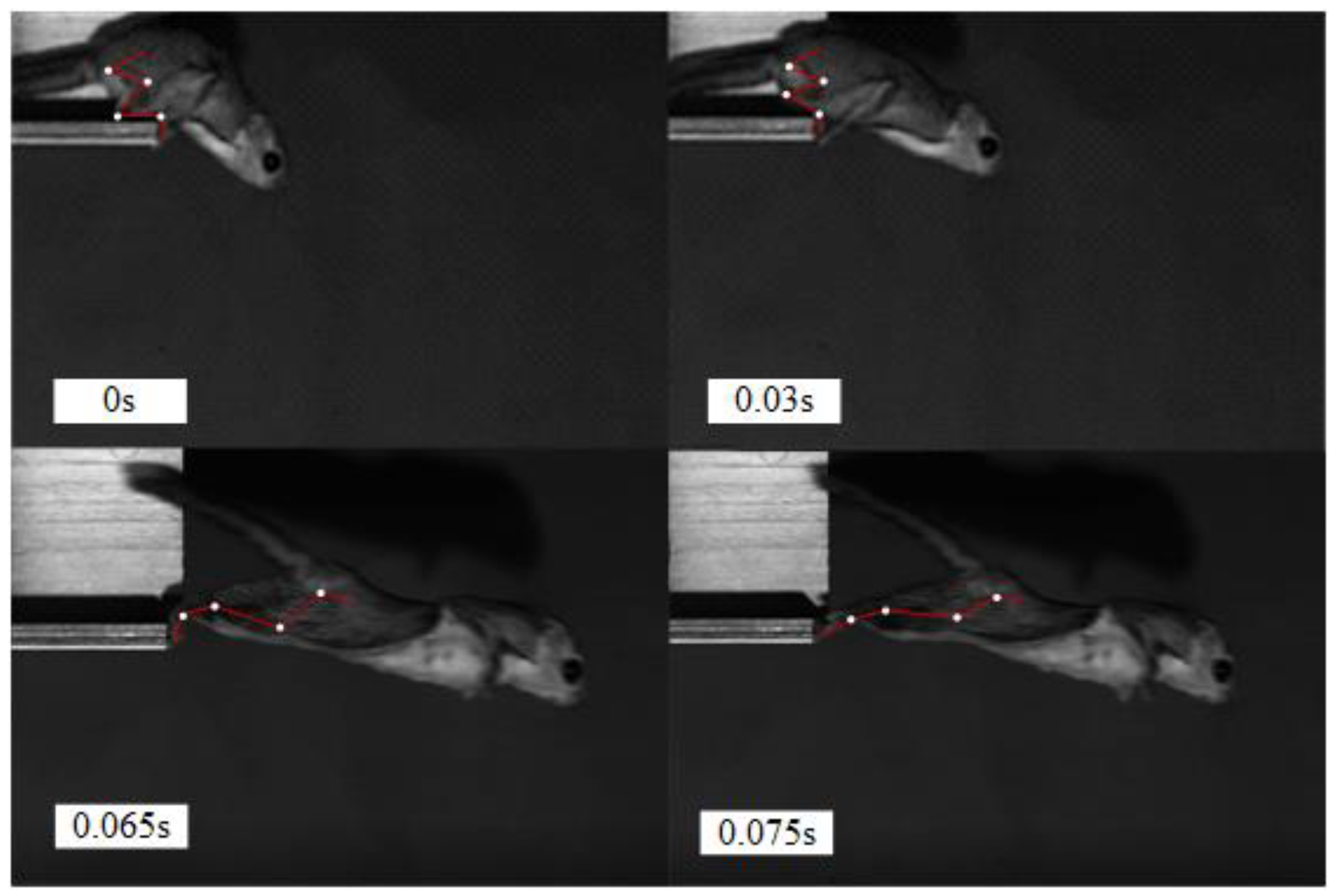
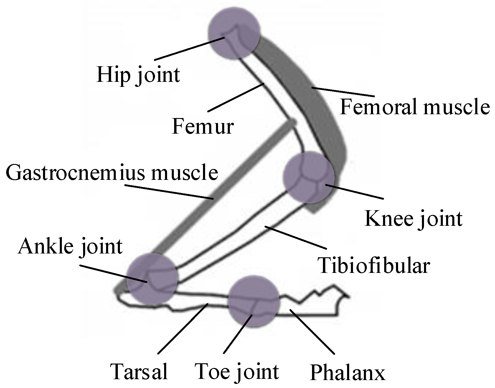
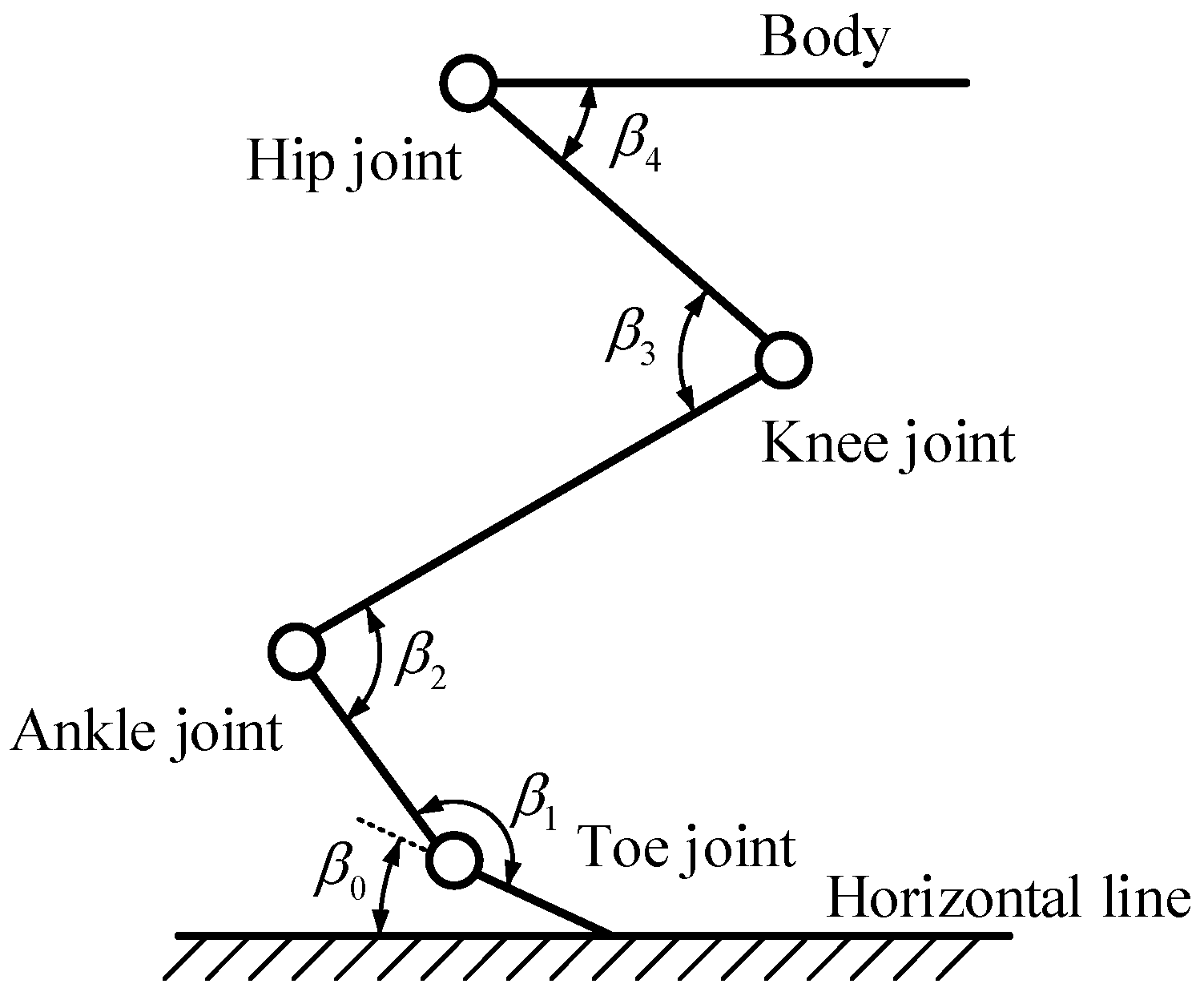
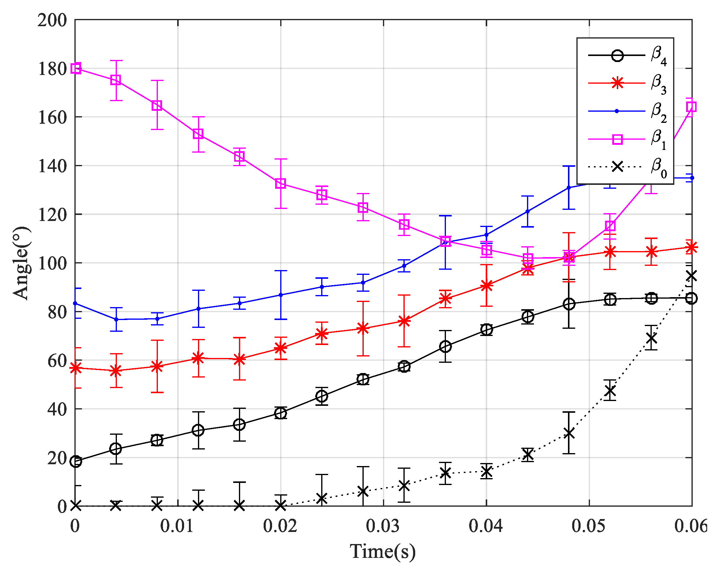
3. Analysis of Jumping Mechanism of Flying Squirrel

The free activity inside confined spaces of an adult male southern flying squirrel (Glaucomys volans) was recorded using a Photron Fastcom Mini UX100 high-speed camera. Sequential images of the flying squirrel during jumping were captured at 2000 frames per second. Figure 3 and Figure 4 exhibit the motional sequence of jumping for gliding and jumping for progress of the flying squirrel, respectively. As shown in Figure 3, the flying squirrel first curls up its hind limbs and supports the body with its forelimbs, then leans forward at the angle of approximately 0° between the body and the horizontal line. Next, it gradually stretches its hind limbs until leaving the hathpace. As shown in Figure 4, when jumping for progress, the flying squirrel likewise uses the stretching of hind limbs to takeoff, but the stance is markedly different: The angle between the body and the horizontal line is approximately 20°.
Similar to most jumping animals, the hind limbs of flying squirrels are the main source of power in jumping movement [40]. As shown in Figure 5, they are made up of femur, tibiofibular, tarsal, and phalanx, including hip joint, knee joint, ankle joint and toe joint. The bones are attached to muscles that can drive the legs for movement. The femoral muscle can drive the knee joint rotation, which provides the main power for the legs. The gastrocnemius muscle can drive the ankle joint rotation, which gives part of the power. The hip joint is connected to the body and can transfer the force generated by stretching the hind limbs to the body. The toe joint acts as a takeoff steering and landing buffer. In addition, the femur and the tibiofibular are connected with the patagium and are able to deploy the patagium along with abduction of the hip joint in the gliding phase.
In order to facilitate the analysis of the movement characteristics of the animal’s hind limbs in the two jumping modes, the joints of hind limbs are simplified into revolute pairs with only one degree of freedom, as shown in Figure 6, where β 0 represents the angle between the phalanx and the horizontal line, β 1 represents the angle of toe joint, β 2 represents the angle of ankle joint, β 3 represents the angle of knee joint, and β 4 represents the angle of hip joint. Reflective paint was used to mark each joint of the hind limbs of the flying squirrel. Then, under the same conditions, we made the flying squirrel repeat the jumping for gliding from a hathpace with a height of 2 m and the jumping for progress on the ground for times, respectively. In addition, the motion process was recorded with the high-speed camera. MATLAB software was used to extract the joint coordinates of the hind limbs on the motion images according to the markers, calculate the angle of each joint, and take the average of the five repetitions. Finally, the change curves of the angle of each joint in the whole motional sequence were plotted, as shown in Figure 7 and Figure 8.
Combined with the motional sequence of jumping for gliding of the flying squirrel, it can be seen from Figure 7 that: β 0 , β 2 , and β 3 are nearly unchanged in the preparation stage of 0~0.03 s; β 0 remains the same while β 2 and β 3 increase quickly with the identical rate of change 54 rad/s in the takeoff stage of 0.03~0.065 s; β 0 increase quickly while β 2 and β 3 grow with slower rate in the launch stage of 0.065~0.075 s; β 2 and β 3 reach the maximum at 0.075 s. Throughout the stage, in addition, β 4 keeps increasing and β 1 almost keeps decreasing with the angle of change of about 85°, which signify the flying squirrel’s body leans forward considerably when it jumps for gliding. Combined with the motional sequence of jumping for progress of the flying squirrel, it can be seen from Figure 8 that: β 2 and β 3 increase quickly with the identical rate of change 28 rad/s in the takeoff stage of 0.02~0.045 s; β 4 and β 1 increase and decrease by about 40°, respectively. The comparison between Figure 7 and Figure 8 indicate that the change trends of angle of hind limbs joints when the animal jump for progress are similar to that when jumping for gliding, but the initial value and the range are obviously different.
The above analysis shows that: Whether jumping for gliding or progress, the flying squirrel both rapidly extend the knee and ankle joint to generate takeoff force, and the change trends of angle of knee and ankle joints are almost synchronized; the rate and range of change of angle of knee and ankle joints are greater when it jumps for gliding, which can produce greater force and speed for takeoff; the angle between body and the horizontal line is smaller when it jumps for gliding, which gives it greater horizontal speed to glide.

4. Design of Jumping Robot
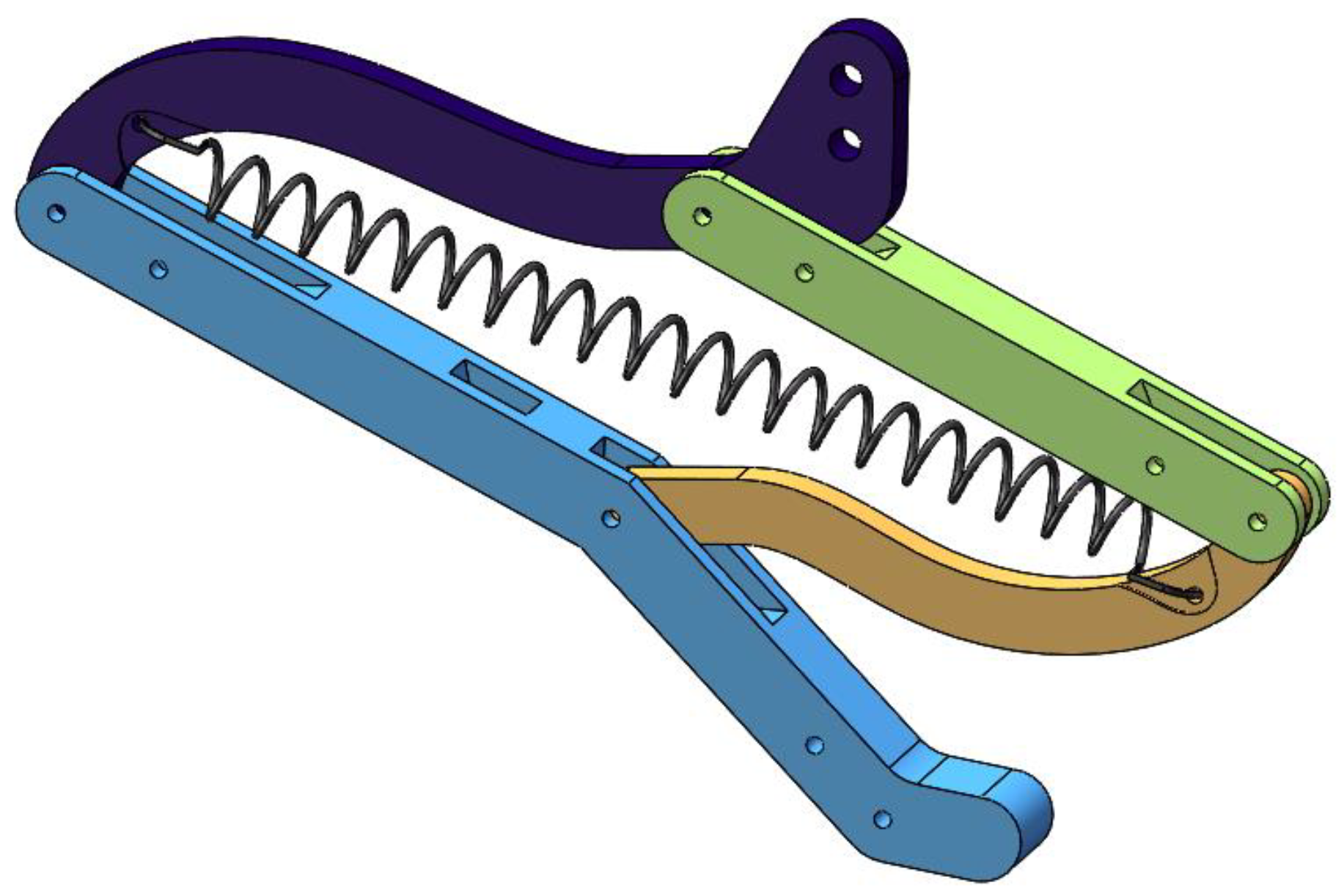
4.1. Hind Limbs

According to the above analysis of the movement characteristics of flying squirrels’ hind limbs, a parallel four-bar linkage mechanism with springs is used to mimic the leg structure of flying squirrels. As shown in Figure 9, the linkage rod a c , b d , d e , a e are connected by hinges successively, where the length l a b and l d e are equal; the length l a e and l b d are equal; the ratio of the length l d e , l b d , and l b c is designed according to the length ratio of the flying squirrel’s femur, tibiofibular and tarsal, approximately l d e : l b d : l b c = 1 : 1 : 1 . The angles β 2 (corresponding to the angle of ankle joint) and β 3 (corresponding to the angle of knee joint) are set to have a constant difference, namely β 2 = β 3 + 20 . Using the linkage rod a e as a frame, the parallel four-bar linkage mechanism a b d e can ensure the angles β 2 and β 3 have the same rate of change.
A spring with a stiffness coefficient of k is connected between points a and d , whose initial length and stretched length are x 0 and x a d , respectively. Ignoring the mass of each rod and spring, we can assume that the takeoff force F T passes through the center of mass (point O ) of the entire robot. In order to determine the structural parameters of the hind limbs, we assume that the elastic potential energy is all converted into kinetic energy without dissipative losses during the takeoff process [13]. Although this assumption does not reflect real-life conditions, it allows for a simple and clear view of the relationship between structural parameters and energy, which is convenient for the initial design. The energy equation is thus
1 2 k n ( x a d x 0 ) 2 = 1 2 m V 0 2
where n represents the number of springs connected in parallel, m represents the mass of entire robot, and V 0 represents the initial velocity after takeoff. According to the geometric relationship, x a d can be acquired as
x a d = 2 l d e cos β 3 2
where β 3 is set to minimum value 30° and maximum value 120°, referring to the variation range of angle of the flying squirrel’s knee joint. When β 3 is 30°, the spring is stretched to its maximum length. In this case, the corresponding V 0 is the initial velocity in the mode of jumping for gliding. According to the average initial velocity of flying squirrels as they glide [35], the corresponding V 0 is set to 3 m/s, and then the length of linkages can be obtained from (1) and (2). The resulting structure of hind limbs is shown in Figure 10.
Takeoff angle θ T (see Figure 9) is defined as the angle between the takeoff force F T and the horizontal line. In order to ensure that the hind limbs do not skid during takeoff, the horizontal component of the takeoff force F T should be less than or equal to the maximum static sliding friction between hind limbs and the ground, namely
F T cos θ T μ 0 F T sin θ T
where μ 0 is coefficient of static friction. Equation (3) is further organized to obtain
μ 0 1 tan θ T
Equation (4) shows that the coefficient of static friction between hind limbs and the ground and the takeoff angle will affect whether the robot can successfully jump. Note that the direction of the takeoff force is perpendicular to the linkage rod a c , and according to the geometric relationship, the takeoff angle can be acquired as
θ T = 260 β 3 γ
where γ (see Figure 9) is the angle between the linkage rod a e and the horizontal line. It can be seen from (5) that the takeoff angle θ T is related to β 3 and γ . For different jumping modes, β 3 and γ have different values. Appropriate materials should be selected at the contact surface between the hind limbs and the ground to avoid skidding according to (4), after the takeoff angle is determined.

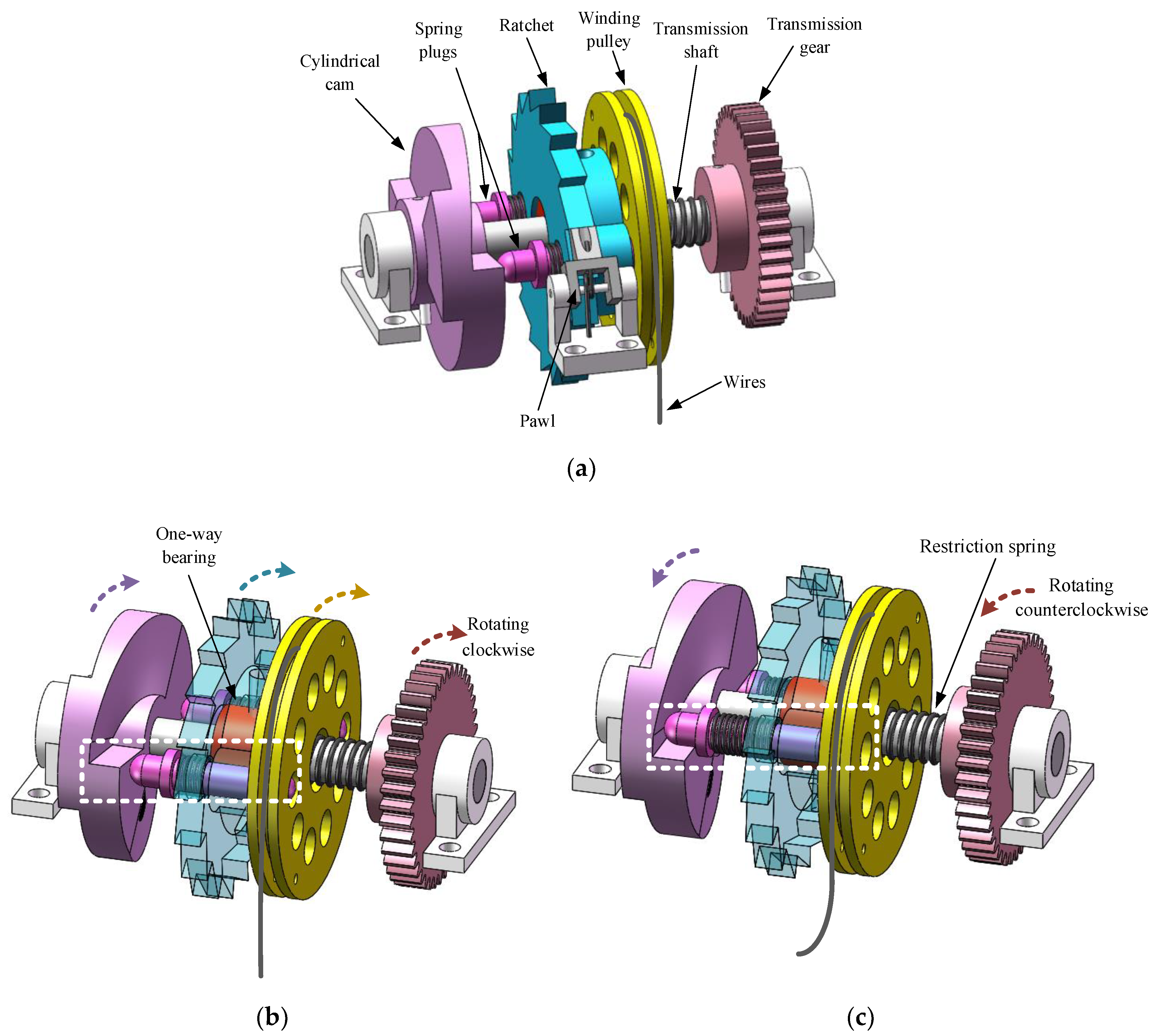
4.2. The Mechanism of Loading and Releasing of Spring

During takeoff, the movement of the hind limbs are driven by the spring, and the energy storage and releasing of the spring are controlled by the loading and releasing mechanism. In order to meet the different requirements of the takeoff speed of the different jumping modes and considering the influence of the overall mass on the jumping performance, the loading and releasing mechanism of the spring should have the following three characteristics besides being able to completely release the stored energy in an instant: 1. The loading degree is controllable; 2. releasing time is controllable; and 3. loading and releasing are driven by the same actuator. Therefore, we designed a mechanism that can realize controllable loading and releasing of the spring, as shown in Figure 11. It is composed of the transmission gear, transmission shaft, cylindrical cam, spring plugs, one-way bearing, ratchet, pawl, winding pulley, restriction spring, and wires. The transmission gear and cylindrical cam are fixed on the transmission shaft. One end of the plugs is in contact with the curved profile of the cylindrical cam, and the other end is inserted into the through hole of the ratchet. The ratchet is mounted on the transmission shaft by the one-way bearing. The winding pulley can rotate freely around the transmission shaft, and its axial movement is constrained by the restriction spring. The wires are wound around the winding pulley and connected to the end of the hind limbs. The overall structure is shown in Figure 11a.
It is assumed that the plugs are inserted into the circumferential distribution holes of the winding pulley under the extrusion of the cylindrical cam at the initial moment. When the transmission gear drives the cylindrical cam to rotate clockwise through the transmission shaft, the ratchet rotates in the same direction and at the same speed with the cylindrical cam under the action of the one-way bearing. Furthermore, the winding pulley also rotates clockwise driven by the plugs, thus winding the wires to compress the structure of the hind limbs, which realizes the loading of springs and storage of energy, as shown in Figure 11b. When the transmission gear drives the cylindrical cam to rotate counterclockwise through the transmission shaft, the ratchet stays still due to the pawl, which causes the plugs to quickly withdraw from the hole in the pulley. In this case, the pulley loses its rotational constraint and instantly loosens the wires to release springs of hind limbs, as shown in Figure 11c. Under the constraint of the restriction spring, continuing counterclockwise rotation of the cylindrical cam causes the plugs to be reinserted into the pulley, ready for the next loading and releasing.
Different from the triggering mechanism of most miniature jumping robots, this completely independent design of loading and releasing allows the springs to be released in an arbitrary state of energy storage, which realizes the active control of takeoff speed. In addition, the combination of one-way bearing and cylindrical cam makes it possible to meet the driving requirements of the mechanism only using a single motor.
The transmission system is shown in Figure 12. The output shaft of the motor transfers the torque to the transmission gear through the two-stage reduction gears, which drives the transmission shaft to rotate clockwise or counterclockwise. The main parameters of each piece of gear are shown in Table A1 (see Appendix A). The transmission ratio of the gears system is
i = ω m ω d = z 1 z m z d z 2 = 4
where ω m and ω d represent the speed of motor and transmission gear, respectively; z m , z 1 , z 2 , and z d represent the number of teeth of the motor gear, gear 1, gear 2, and transmission gear, respectively.
It is assumed that, during loading, the tension on the wires is F r , and its direction is the same as that of the takeoff force F T (see Figure 9); the spring force of hind limbs is F s . Ignoring the mass of each rod and spring, and according to the torque balance equation, the relation between F r and F s is expressed as
F r [ l a c l a e sin ( θ T + γ 180 ) ] = F s l d e sin β 3 2
where F s = k ( x a d x 0 ) . Combined with (2) and (5), (7) can be further arranged as
F r = k ( l d e sin β 3 x 0 sin β 3 2 ) 2 sin 80 sin ( 80 β 3 )
Thus, the torque that the motor needs to provide is
T m = n F r d r 2 i
where n represents the number of springs connected in parallel, and d r represents the diameter of the winding pulley. According to (8) and (9), when the structural parameters and springs are determined, the torque that the motor needs to provide is related to the angle β 3 . The known conditions are l d e = 38 mm , k = 0.52 N / mm , x 0 = 35 mm , n = 2 and d r = 26 mm . Then, the relation between the motor’s torque and the angle β 3 is presented in Figure 13. The maximal available torque of the selected motor is 0.16 Nm when operated by the 4.8 V Li-Po battery. It can be seen that the maximal torque in the curve is roughly 0.033 Nm, indicating that there is much more available potential power using this transmission system.

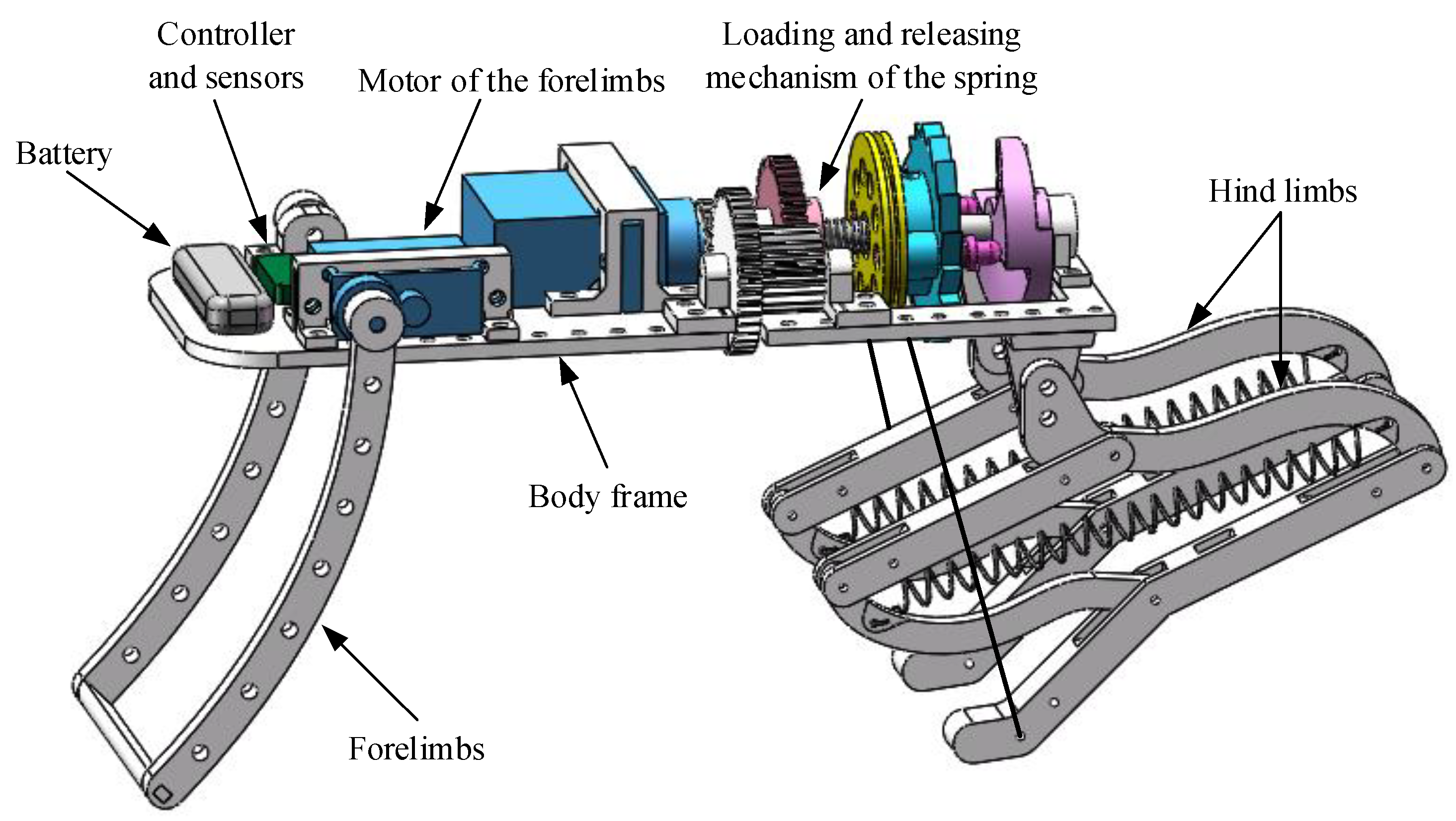
4.3. Forelimbs and Overall Structure

In order to meet the different requirements of the takeoff stances of the different jumping modes, the forelimbs should not only support the body during takeoff, but also adjust the body posture. Thus, the forelimbs are connected to a motor fixed to the body frame and are driven by the motor to swing relative to the body frame.
The 3D model of the overall structure is presented in Figure 14. The hind limbs are fixedly connected with the body frame. The loading and releasing mechanism of the spring can realize controllable compression of hind limbs. The forelimbs can adjust the angle between the body frame and the horizontal line to change the body stance. The controller is used to control the rotation of the motors, and the sensor is used to detect the number of turns of the pulley and the body posture. The battery powers the whole system.

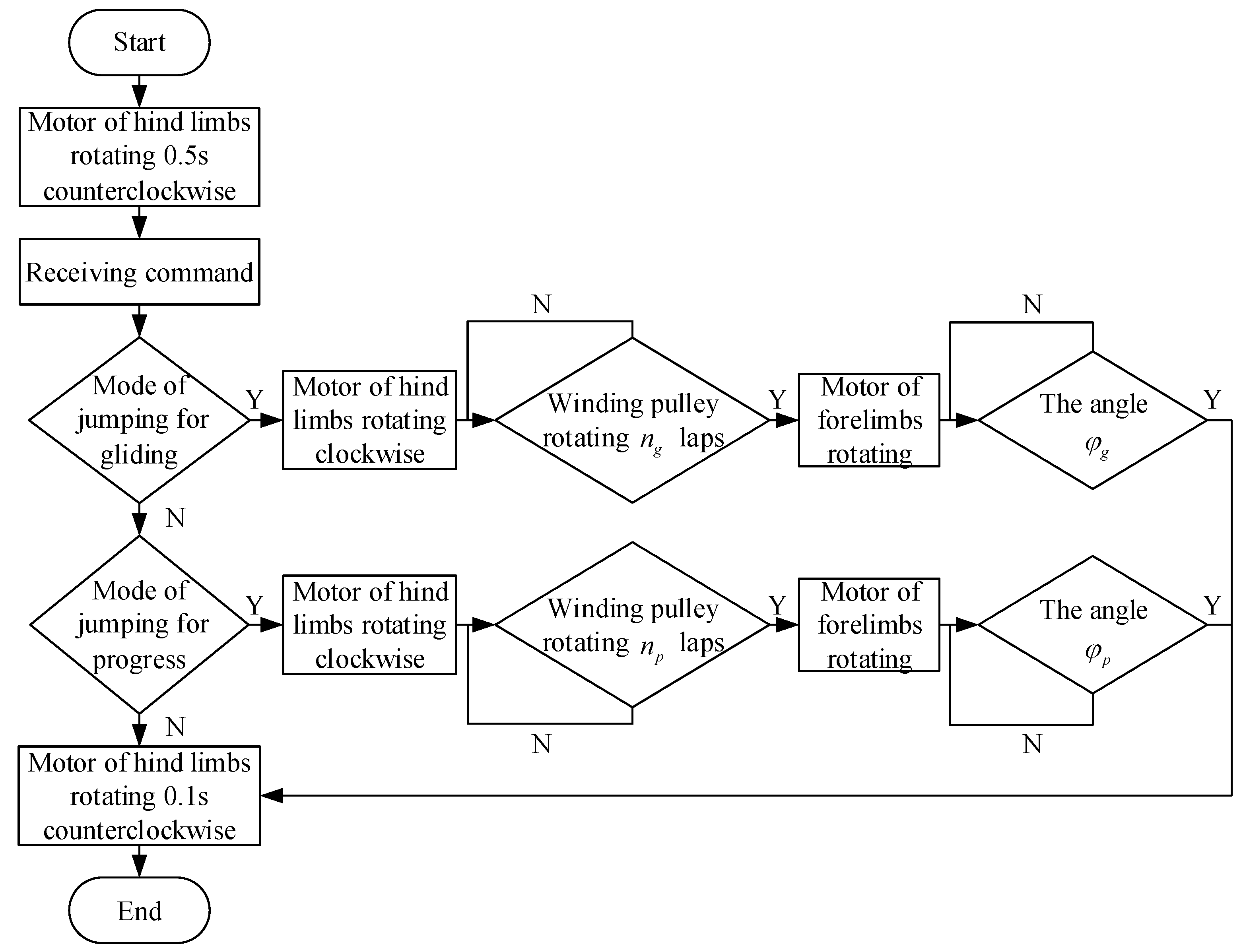
4.4. The Working Process

Before the start of jumping, the hind limbs are at fully extended position. Once ready to jump, the controller first controls the motor of the hind limbs to rotate counterclockwise for 0.5 s, so that the spring plugs are inserted into the hole of the winding pulley, and then waits for the command. When the controller receives the command of the mode of jumping for gliding, it first controls the motor of the hind limbs to rotate clockwise until the sensors detect that the number of turns of the pulley is n g , and then stops the rotation. Then the motor of the forelimbs is rotated until the sensors detect that the angle between the body frame and the horizontal line is φ g . When the controller receives the command of the mode of jumping for progress, it first controls the motor of the hind limbs to rotate clockwise until the sensors detect that the number of turns of the pulley is n p , and then stops the rotation. Then the motor of the forelimbs is rotated until the sensors detect that the angle between the body frame and the horizontal line is φ p . After the stance adjustment is completed, the controller controls the motor of the hind limbs to rotate 0.1 s counterclockwise, so that the spring plugs are withdrawn from the hole of the winding pulley, and the springs of the hind limbs are released quickly to complete the corresponding jumping. Its workflow is shown in Figure 15.
According to the initial angle of the knee joint and the angle between the body and the ground of the flying squirrel in different jumping modes, when the pulley rotates n g laps and n p laps, the angle β 3 are set as 30° and 60°, respectively, and the angle φ g and φ p are set as 0° and 20°, respectively. As shown in Figure 16, the dotted lines represent the initial state of the hind limbs, and the solid lines represent the compressed state of the hind limbs. The curve c c represents the trajectory of the end of the hind limbs. The length l c c of the curve c c can be expressed as
l c c = 2 π l d e ( 120 β 3 ) cos 10 180
Since the wires are connected to the end of the hind limbs, n g and n p can be acquired as
n g = l d e cos 10 d r 1 . 5
n p = 2 l d e cos 10 3 d r 1

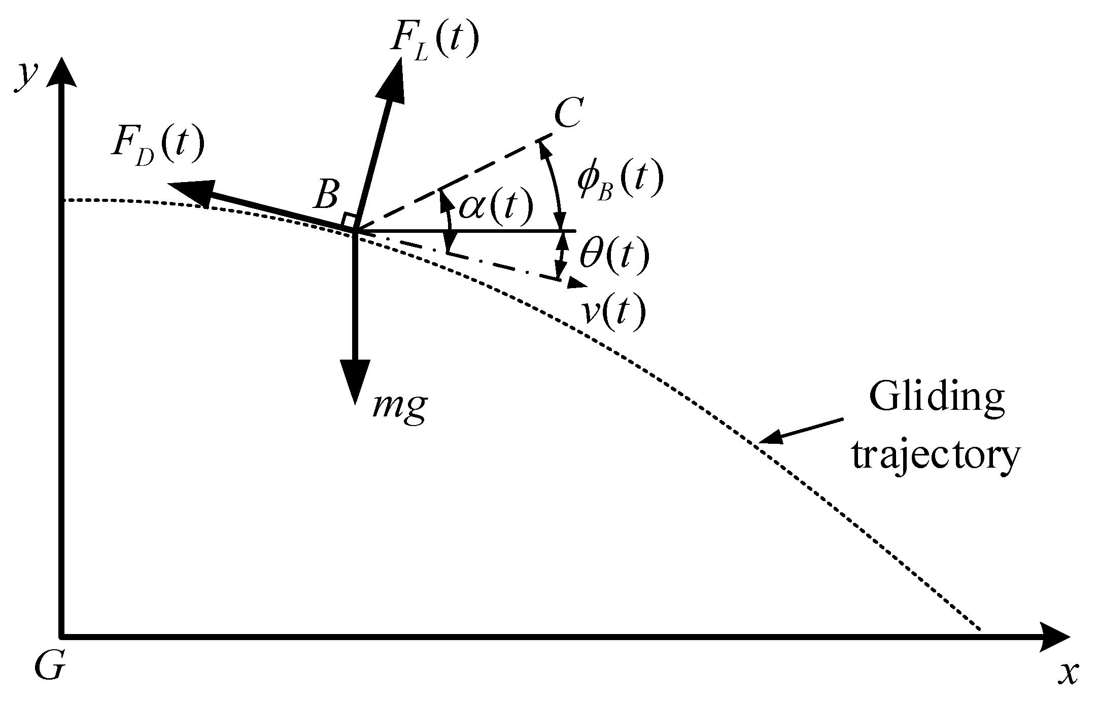
5. Pitching Requirement and Adjustment

According to the workflow of the robot, the initial pitch angle is 0° when the robot takeoff in the mode of jumping for gliding. Ideally, if the takeoff direction goes through the center of mass, the robot will remain in this posture until it enters the glide stage. However, taking into account the changes in the position of the center of mass caused by manufacturing and assembly errors, it is likely that there will be additional angular velocities after the robot takeoff, which will lead to changes in the robot’s posture. The aerial posture plays a decisive role in the performance of the gliding. Therefore, it is necessary to define the aerial posture requirement according to the relationship between gliding attitude and gliding performance, and then adjust the posture to achieve the design goal.

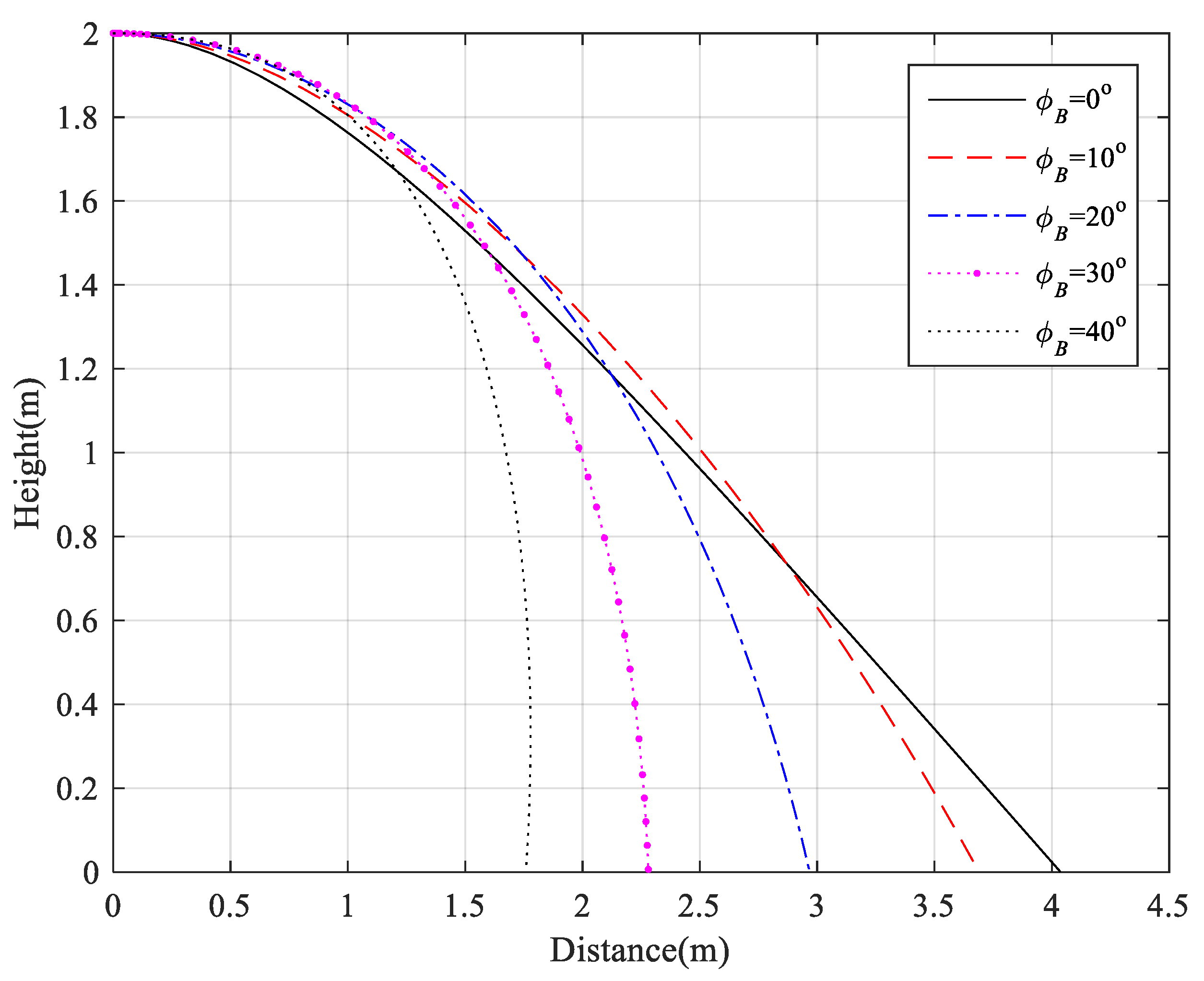
5.1. Pitching Requirement

According to the locomotion conceiving of flexible wing-limb blending platform, the robot needs to unfold the main membrane at the top after takeoff and then to glide. The ratio of the horizontal distance to the vertical height in the whole gliding process is called the glide ratio, which is one of the key indicators of gliding performance [39]. The larger the value, the better the gliding performance. Therefore, the aerial posture of the robot at the top should meet the requirements for the robot to obtain the maximum glide ratio.
In order to facilitate the analysis, the influence of different pitching posture on the glide ratio is only considered in this paper. As shown in Figure 17, the rectangular coordinate frames { G } is built. Assuming that the robot is located at a point on the gliding trajectory at time t, its position coordinate is ( x ( t ) , y ( t ) ) ; its speed is v ( t ) ; the angle between its speed and horizontal line is θ ( t ) ; the angle between its body axis B C and horizontal line is ϕ B ( t ) ; the angle of attack is α ( t ) . The forces on the robot are the gravity m g , drag force F D ( t ) and lift force F L ( t ) . The direction of drag force is opposite to the direction of speed, and the direction of lift force is perpendicular to the direction of speed. According to the D’Alembert’s principle, the equilibrium equations of forces can be expressed as
{ m x ¨ ( t ) = F D ( t ) cos θ ( t ) + F L ( t ) sin θ ( t )     m y ¨ ( t ) = m g + F D ( t ) sin θ ( t ) + F L ( t ) cos θ ( t )
According to the theory of aerodynamics, F D ( t ) and F L ( t ) can be acquired as
{ F D ( t ) = 1 2 C D S ρ v 2 ( t ) F L ( t ) = 1 2 C L S ρ v 2 ( t )
where C D and C L represent drag coefficient and lift coefficient, respectively; S and ρ denote the area of the wing membranes and the density of air, respectively. The relationship between drag, lift coefficients, and the attack angle can be expressed as [41]
{ C D = 2 sin 2 α ( t )       C L = 2 sin α ( t ) cos α ( t )  
Assuming that the robot can use its tail membrane to achieve pitching moment balance like a flying squirrel during gliding [42], the pitch angle ϕ B ( t ) remains constant, and
ϕ B = α ( t ) θ ( t )
Since,
{ cos θ ( t ) = x ˙ ( t ) x ˙ 2 ( t ) + y ˙ 2 ( t ) sin θ ( t ) = y ˙ ( t ) x ˙ 2 ( t ) + y ˙ 2 ( t )
Equation (13) can be further arranged as
{ x ¨ ( t ) = C 0 C 1 x ˙ 3 ( t ) + C 0 ( C 2 C 4 ) x ˙ ( t ) y ˙ 2 ( t ) x ˙ 2 ( t ) + y ˙ 2 ( t )         1 2 C 0 C 3 x ˙ 2 ( t ) y ˙ ( t ) + y ˙ 3 ( t ) x ˙ 2 ( t ) + y ˙ 2 ( t ) y ¨ ( t ) = g + C 0 C 2 y ˙ 3 ( t ) + C 0 ( C 1 + C 4 ) x ˙ 2 ( t ) y ˙ ( t ) x ˙ 2 ( t ) + y ˙ 2 ( t )     1 2 C 0 C 3 x ˙ 3 ( t ) + x ˙ ( t ) y ˙ 2 ( t ) x ˙ 2 ( t ) + y ˙ 2 ( t )
where C 0 = ρ S m , C 1 = sin 2 ϕ B , C 2 = cos 2 ϕ B , C 3 = sin ( 2 ϕ B ) , and C 4 = cos ( 2 ϕ B ) . It is the second-order ordinary differential equation set of x ( t ) and y ( t ) . The ODE45 solver [43] in MATLAB is used for numerical simulation with parameters: m = 0.08 kg , g = 9.8 m · s 2 , ρ = 1.2 kg · m 3 , S = 0.04 m 2 , v ( 0 ) = 3 m · s 1 , and the gliding trajectory with different pitch angle can be obtained, as shown in Figure 18. It can be seen from Figure 18 that, when the robot glides from 2 m height at the initial horizontal velocity of 3 m/s, the glide distance will be farthest 4.04 m if the pitch angle is 0°, and the corresponding glide ratio will be maximal 2.02. When the pitch angle increases to 10°, the glide distance decreases to 3.69 m, which is 91.3% of the maximum distance. However, when the pitch angle increases to 20°, 30°, and 40°, the glide distance decreases to 73.5%, 56.4%, and 43.5% of the maximum distance, respectively. Therefore, in order to obtain a large glide distance and glide ratio, the pitch angle of the robot should be within 0°~10° when it reaches the top in the mode of jumping for gliding.

5.2. Pitching Adjustment

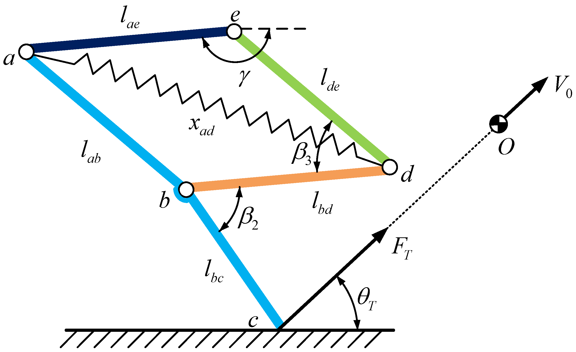
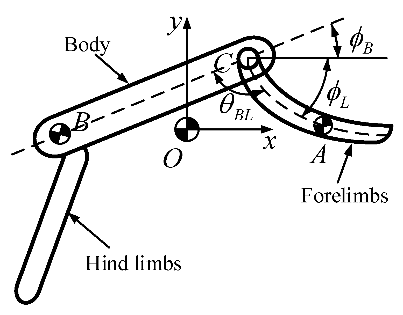
5.2.1. Dynamic Model

In this paper, the swing of the forelimbs is used to adjust the pitch attitude of the robot. Because the hind limbs no longer move relative to the body after takeoff, the hind limbs and the body can be regarded as the same rigid body. As shown in Figure 19, the center of mass of the forelimbs, the body containing the hind limbs, and the entire robot are located at point A , point B , and point O , respectively. The mass of the forelimbs and the body are m L and m B , respectively. The forelimbs can swing around point C on the body. The length between point A and point C is l A C . The length between point B and point C is l B C . The angle between the forelimbs and the horizontal line is ϕ L . The angle between the body and the horizontal line is ϕ B . The angle between the body and the forelimbs is θ B L .
The rectangular coordinate frame { O } is set up on the point O . In frame { O } , the x axis points to the horizontal direction, and the y axis points to the vertical direction. They denote the coordinates for point A and point B in frame { O } as r O A and r O B , respectively. They can be obtained using the relation
m L r O A + m B r O B = 0
The Lagrange equation is used for dynamics modeling, and its expression is
d d t ( L q ˙ i ) L q i = Q i     ( i = 1 , , n )
where q i is the i th generalized coordinate; Q i is the generalized force corresponding to q i ; L is the Lagrange function, which is equal to the difference between the kinetic energy and the potential energy of the system. Igoring the height change in the ascent stage, we only consider the influence of the swing of the forlimbs on the aerial posture [26]. In this case, the robot’s potential energy is zero. Therefore, the system’s total energy is the sum of the kinetic energy of the forelimbs and body, namely
L = 1 2 J L ϕ ˙ L 2 + 1 2 m L | | r ˙ O A | | 2 2 + 1 2 J B ϕ ˙ B 2 + 1 2 m B | | r ˙ O B | | 2 2
where J L and J B denote the moment of inertia of the forelimbs and body when their axes of rotation pass through the point C , respectively. Further, (19) and (21) can be combined and arranged as
L = 1 2 [ J L ϕ ˙ L 2 + J B ϕ ˙ B 2 + m L m B ( l A C 2 ϕ ˙ L 2 + l B C 2 ϕ ˙ B 2 + 2 l A C l B C ϕ ˙ L ϕ ˙ B cos θ B L ) m L + m B ]
Neglecting the air resistance, Equation (20) can be written as
{ d d t ( L ϕ ˙ L ) L ϕ L = τ d d t ( L ϕ ˙ B ) L ϕ B = τ
where τ is the the actuation torque from the motor. Combining (22) and (23), we obtain the dynamics equation as
{ M ϕ ¨ L K ϕ ¨ B cos θ B L K ϕ ˙ B 2 sin θ B L = τ N ϕ ¨ B + K ϕ ¨ L cos θ B L + K ϕ ˙ L 2 sin θ B L = τ
where M = J L + m L m B l A C 2 m L + m B ,   N = J B + m L m B l B C 2 m L + m B ,   K = m L m B l A C l B C m L + m B
Due to the nonlinear coupling between ϕ L and ϕ B , it is difficult to transform (24) into an equation only containing ϕ B and τ . Therefore, the state variable θ B L is used for solving by following two steps. First, substitute θ B L = π ϕ L ϕ B into (24) to obtain
ϕ ¨ L = H K ϕ ˙ L 2 cos θ B L H N ϕ ˙ B 2 G τ E
ϕ ¨ B = H M ϕ ˙ L 2 + H K ϕ ˙ B 2 cos θ B L D τ E
where D = M K cos θ B L , G = N K cos θ B L , H = K sin θ B L , E = M N K 2 cos 2 θ B L .
From θ ¨ B L = ϕ ¨ L ϕ ¨ B , (25) and (26) can be arranged as
θ ¨ B L = H D ϕ ˙ L 2 + H G ϕ ˙ B 2 E + D + G E τ
Second, we utilize the conservation of angular momentum to further arrange (27). If the air resistance is negligible, the angular momentum of the total system with respect to the point O is a constant, namely
L O = J L ϕ ˙ L + r O A × m L r ˙ O A + J B ϕ ˙ B + r O B × m B r ˙ O B   = G ϕ ˙ B D ϕ ˙ L   = c o n s t a n t
Since θ ˙ B L = ϕ ˙ B ϕ ˙ L , ϕ ˙ L and ϕ ˙ B can be solved as
ϕ ˙ L = G θ ˙ B L L O D + G
ϕ ˙ B = D θ ˙ B L + L O D + G
Substitute (29) and (30) into (27) to obtain
θ ¨ B L = D G H θ ˙ B L 2 + H L O 2 E ( D + G ) + D + G E τ
For the forelimbs motor actuated by a constant rated voltage supply, its torque τ is related to its angular speed θ ˙ B L by
τ = τ s ( 1 θ ˙ B L / ω 0 )
where τ s is the motor’s stall torque, and ω 0 is the no-load angular speed. Therefore, (31) becomes a second-order ordinary differential equation for θ B L , namely
θ ¨ B L = D G H θ ˙ B L 2 + H L O 2 E ( D + G ) + D + G E τ s ( 1 θ ˙ B L ω 0 )
Finally, by solving θ B L from (33) and combining with (30), the pitch angle of the body can be obtained as
ϕ B = D θ ˙ B L + L O D + G d t + ϕ B ( 0 )
where ϕ B ( 0 ) is the initial angle between the body and horizontal line.

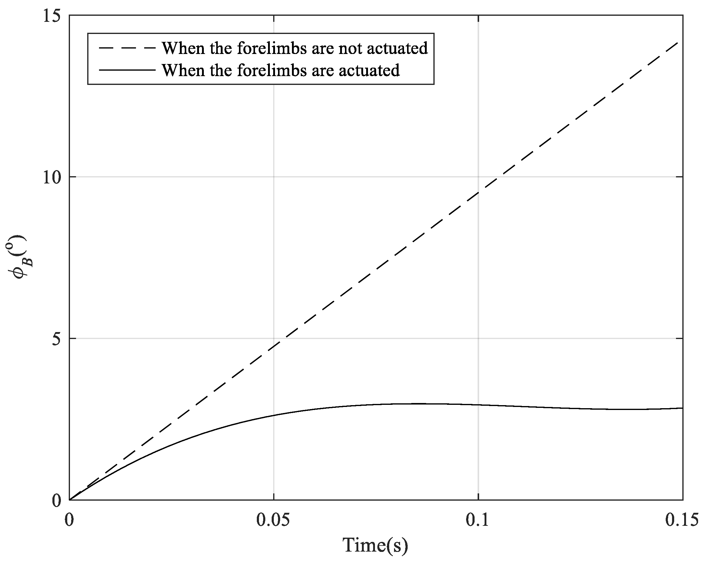
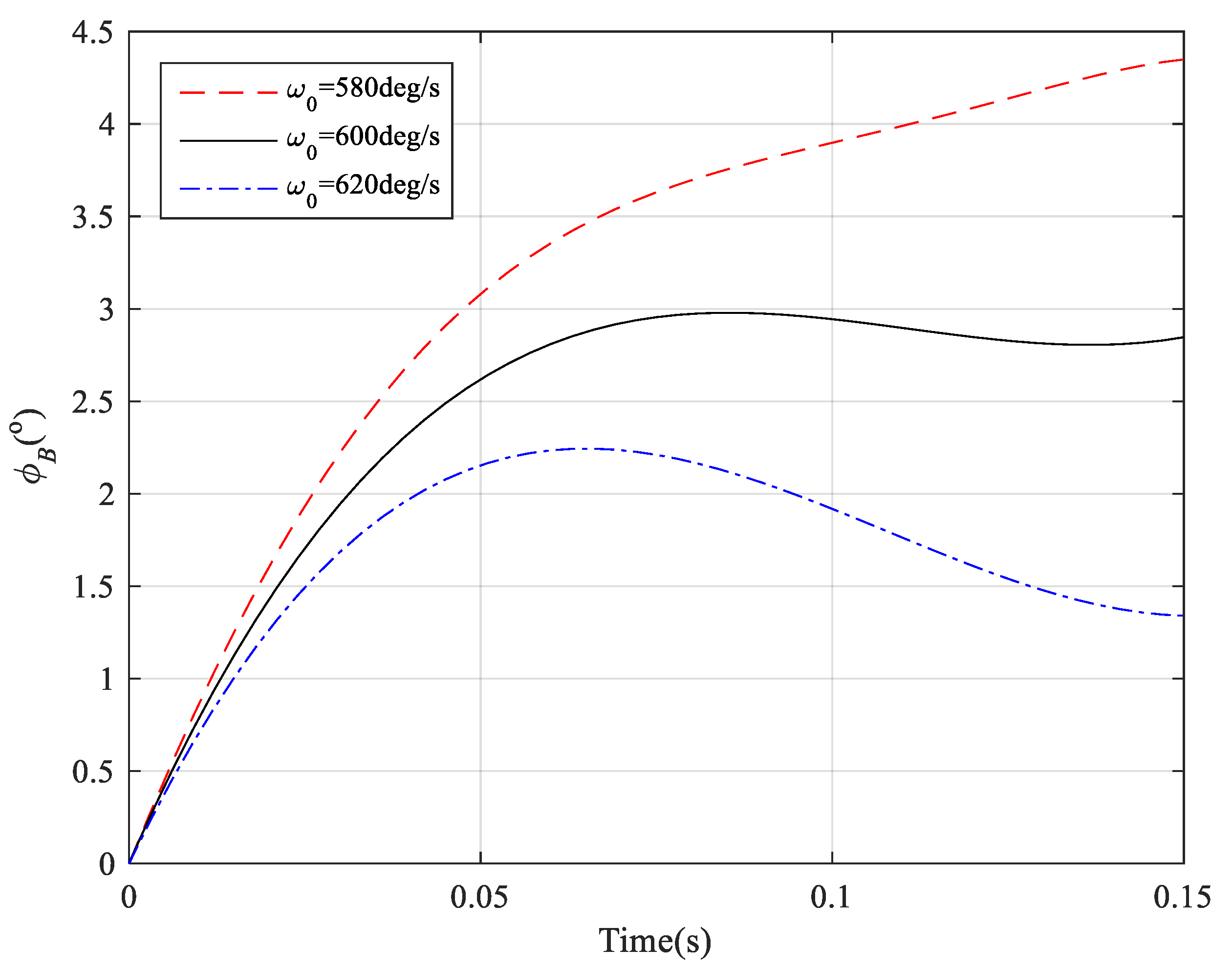
5.2.2. Numerical Simulation

The above dynamics model is simulated using MATLAB to verify the feasibility of adjusting the pitching posture by the forelimbs in this section. Assuming that the additional angular velocity is 95 deg/s when the robot takes off at t = 0 in the mode of jumping for gliding. The simulation parameters are tabulated in Table 1, and the simulation results are shown in Figure 20. It can be seen from Figure 20 that when the forelimbs are not actuated and remain stationary relative to the body, the pitch angle of the body increases linearly under the action of additional angular velocity, reaching 14° at 0.15 s (dotted line in Figure 20); when the forelimbs swing away from the body driven by the forelimbs motor with a stall torque of 0.15 N·m and a no-load angular speed of 600 deg/s, the pitch angle of the body first increases from 0° to 3°, and then basically stops changing (solid line in Figure 20).
With the same other simulation parameters, the changes of the pitch angle of the body under different no-load angular speeds of the forelimbs motor are shown in Figure 21. It can be seen from Figure 21 that when the no-load angular speed decreases to 580 deg/s, the pitch angle of the body increases from 0° to 4.3° within 0~0.15 s; when the no-load angular speed increases to 620 deg/s, the pitch angle of the body first increases from 0° to 2.2°, and then gradually decreases to 1.4° within 0~0.15 s.
The above simulation results show that the pitching posture of the body can be adjusted by driving the forelimbs to swing relative to the body after the robot takeoff. In the case of jumping for gliding with initial angular momentum (counterclockwise rotation), the change of pitching attitude caused by the additional angular velocity can be inhibited by the forelimbs swinging away from the body, and the inhibition effect is related to the no-load angular speed of the forelimbs motor: The greater the angular speed is, the more significant the inhibition effect is.

6. Prototype and Experiment

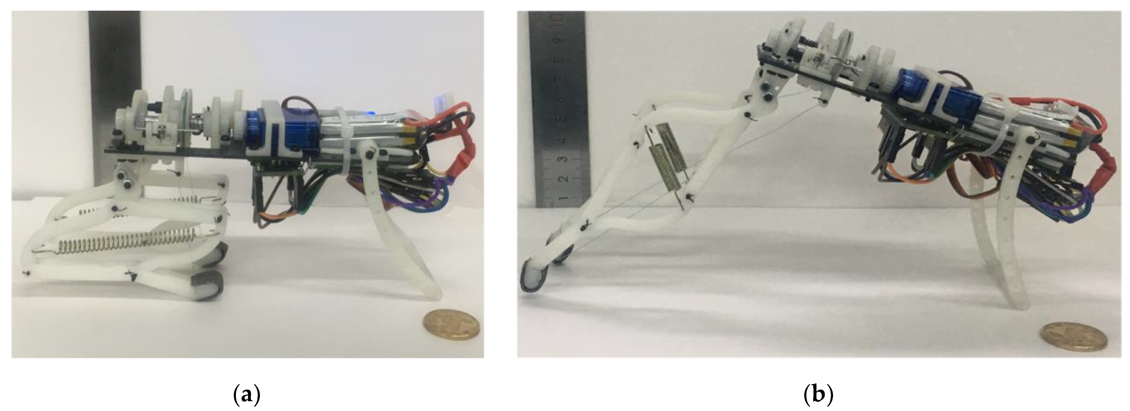
6.1. Prototype Manufacture

In order to reduce the weight of the prototype as much as possible, we used the materials with low density and high strength to make the prototype. The body frame was made of a 2 mm carbon fiber plate, which was laser-cut and had a size of 117 mm × 44 mm. The cam, ratchet, gears, pulley, rods, and brackets were 3D-printed from photosensitive resin materials. The transmission shaft was made of aluminum alloy with a diameter of 4 mm. In addition, the ends of hind limbs were pasted with thin rubber pads to increase the friction between the hind limbs and the ground.
The S0090D-R 360° continuous rotating digital motor with a mass of 9 gr and a stall torque of 1.6 kg·cm (4.8 V) was used as the motor of the hind limbs, and the S0025 digital motor with a mass of 3 gr and a rotatable angle of 90° was used as the motor of the forelimbs. They both are produced by Doman® RC Hobby Co. Ltd located in Shenzhen, China. The SS451A hall sensor made by Honeywell® Company located in Morristown, New Jersey, USA was used to detect the number of turns of the winding pulley. The MPU6050 inertial measurement unit (IMU) produced by the InvenSense® company located in San Jose, California, USA was used to detect the pitch angle, and it contains a three-axis gyroscope and a three-axis accelerometer, which can measure the attitude information of the robot. We used the HC-05 Bluetooth module for wireless communication, and its effective transmission distance is 10 m. The Arduino Nano board was used as the central processing unit. It integrates an ATmega328 microcontroller with 6 PWM outputs. The size is 18 mm × 45 mm, and the weight is only 7 gr. The total energy for the robot is provided by a 150 mAh LiPo battery with 7.4 V voltage input. The size of the fully assembled prototype is about 180 mm × 50 mm × 110 mm, and the overall weight including the battery and control system is 83 gr. Figure 22a,b shows the jumping robot at fully flexed and fully extended positions, respectively. The materials and weights of components of the prototype are summarized in Table 2.

6.2. Jumping Performance

In order to analyze the performance of the prototype in different jumping modes, a high-speed camera (Photron Fastcom Mini UX100) was placed perpendicular to the jumping plane to record posture and trajectory changes. The camera was operated at a recording speed of 1000 frames per second. A board with 80 cm × 100 cm grid coordinates behind the robot was used to estimate the position of the robot.

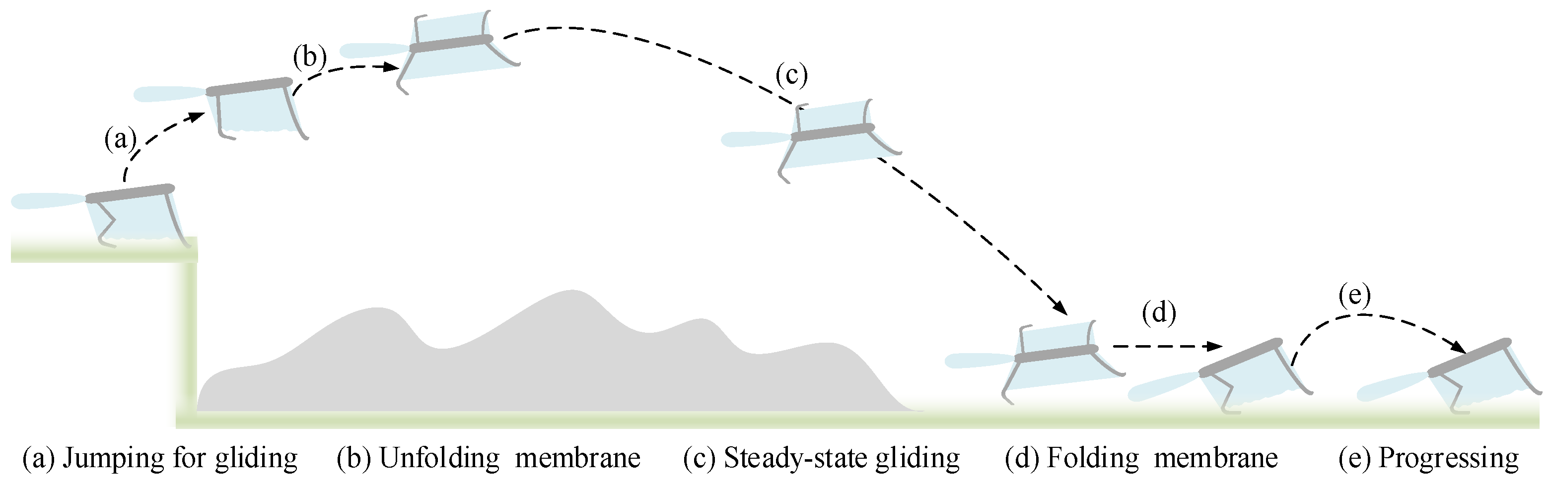
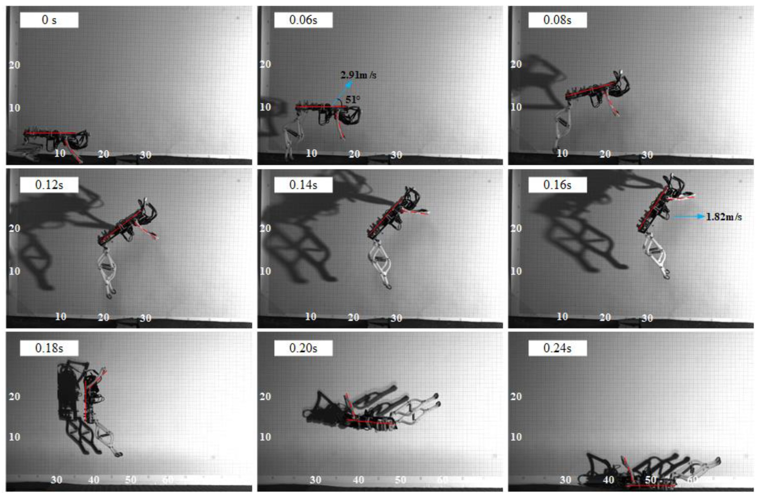
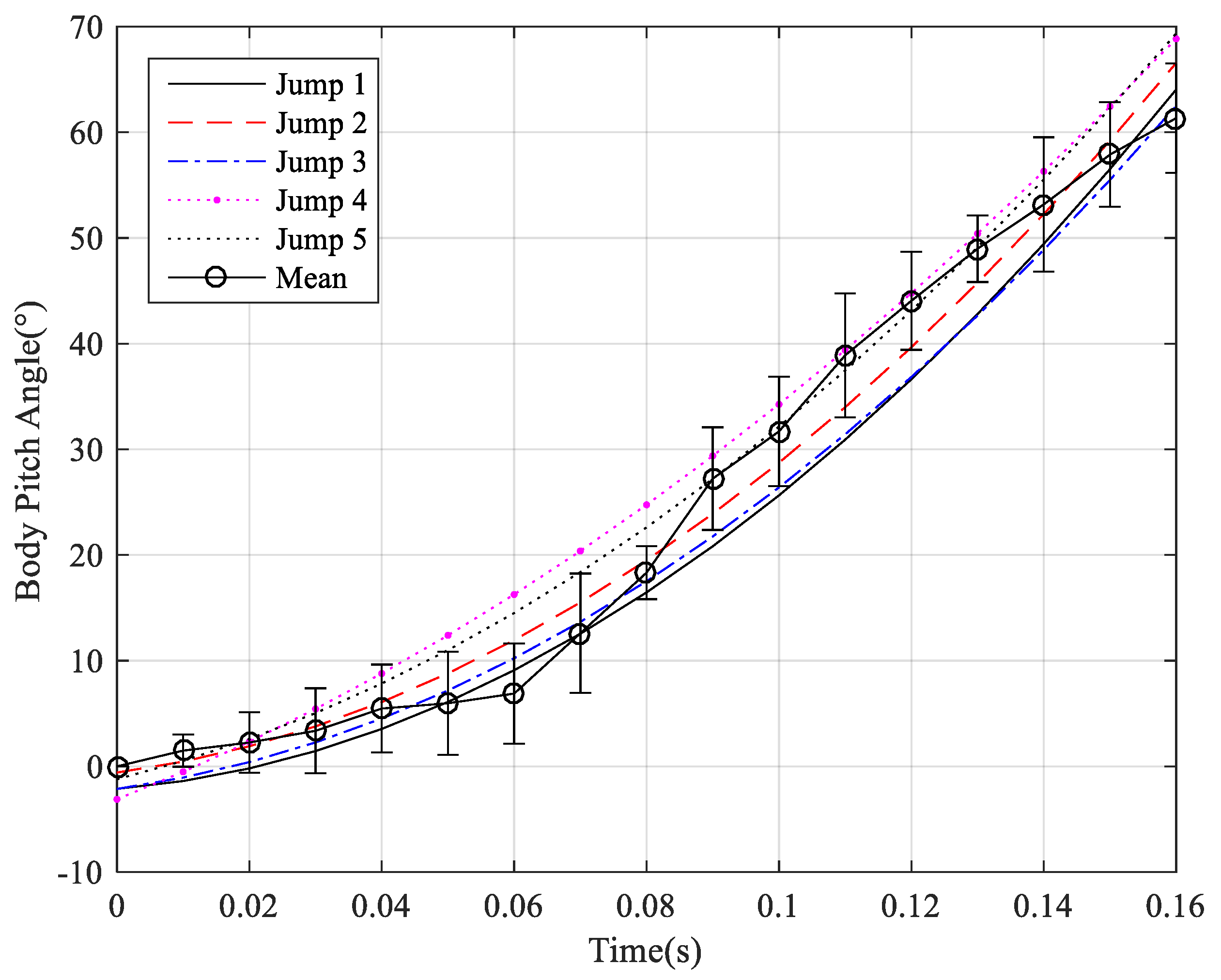
6.2.1. The Mode of Jumping for Gliding

According to the workflow of the mode of jumping for gliding, 1.5 turns of the pulley and 0° of the angle between the body and the ground were taken as the initial state before jumping. The motion sequence when the forelimbs were not actuated in the process of jumping is shown in Figure 23. It can be seen from Figure 23 that the prototype leaves the ground after 0.06 s from the initial time with the velocity of 2.91 m/s and the takeoff angle of 51°; the prototype reaches the highest point of the jump trajectory at 0.16 s with the velocity of 1.82 m/s and the height of 21 cm; the pitch angle of the prototype gradually increases from 0° to 56° within 0~0.16 s, and the rate of change of angle is about 357 deg/s. Due to the continuous increase of the pitch angle, the prototype finally lands in an inverted position at 0.24 s.
With the same initial state before jumping, the forelimbs were actuated to swing counterclockwise at the speed of 600 deg/s once the onboard IMU detected the acceleration change of the prototype. The motion sequence when the forelimbs were actuated in the process of jumping is shown in Figure 24. It can be seen from Figure 24 that the prototype leaves the ground after 0.06 s from the initial time with the velocity of 3.07 m/s and the takeoff angle of 31°; the prototype reaches the highest point of the jump trajectory at 0.16 s with the velocity of 2.63 m/s and the height of 13 cm; the pitch angle of the prototype gradually increases from 0° to 9.6° within 0~0.16 s, and the rate of change of angle is about 59 deg/s. Due to the impact and the springs of hind limbs, the prototype inevitably oscillates as it lands and ends up on its side.
Compared to the jumping with the relatively stationary forelimbs, the increase of pitch angle when jumping with the swinging forelimbs is obviously inhibited as shown in Figure 24. The pitch angle at the highest point of the trajectory is less than 10°, which meets the demand of aerial attitude when obtaining excellent gliding performance. In addition, since the hind limbs are fixed on the body frame, the swing of the forelimbs not only affects the pitching posture of the body, but also changes the direction of the takeoff force, thus leading to the takeoff angle smaller. This change reduces the jumping height and increases the horizontal velocity of the prototype, which is helpful to obtain greater aerodynamic force after the wing membrane is unfolded and improve the gliding performance.
Figure 25 and Figure 26 show the variation of pitch angle with respect to time for the five jumps for gliding when the forelimbs are not actuated and the forelimbs swing, respectively. The data in the figures are collected by the onboard IMU, and the data update frequency is 100 Hz. The curves are fitted by polynomial functions in MATLAB software. It can be seen from Figure 25 that the pitch angles of all the five jumps increase from about 0° at the initial point to about 65° at the highest point of the jumping trajectory when the forelimb is not actuated. It can be seen from Figure 26 that when the forelimbs swing counterclockwise, the pitch angles increase only from about 0° to about 10° for all five jumps. It should be noted that the angles shown in Figure 25 do not change linearly as the dotted line in the simulation result Figure 20. The reason is that the forelimbs can rotate slightly during takeoff even though it is not actuated due to inertia. Compared with the solid line in Figure 20, the curves shown in Figure 26 present a trend of decreasing within 0~0.02 s. This is due to the forelimbs swinging at the beginning of the jump when the takeoff force is small, which makes the impact of the forelimbs swinging on the body posture greater than the change in posture caused by the takeoff force that has not passed the center of mass, while in the theoretical analysis and simulation calculation, the entire takeoff process is simplified.
The above experimental results show that when the robot jumps in the mode of jumping for gliding, the body’s pitch posture can be effectively adjusted by driving the forelimbs to swing away from the body at an angular velocity of 600 deg/s. This way, the body’s pitch angle at the highest point of the jumping trajectory is maintained at 0°~10°, so as to meet the requirements of the subsequent gliding movement for the aerial attitude.

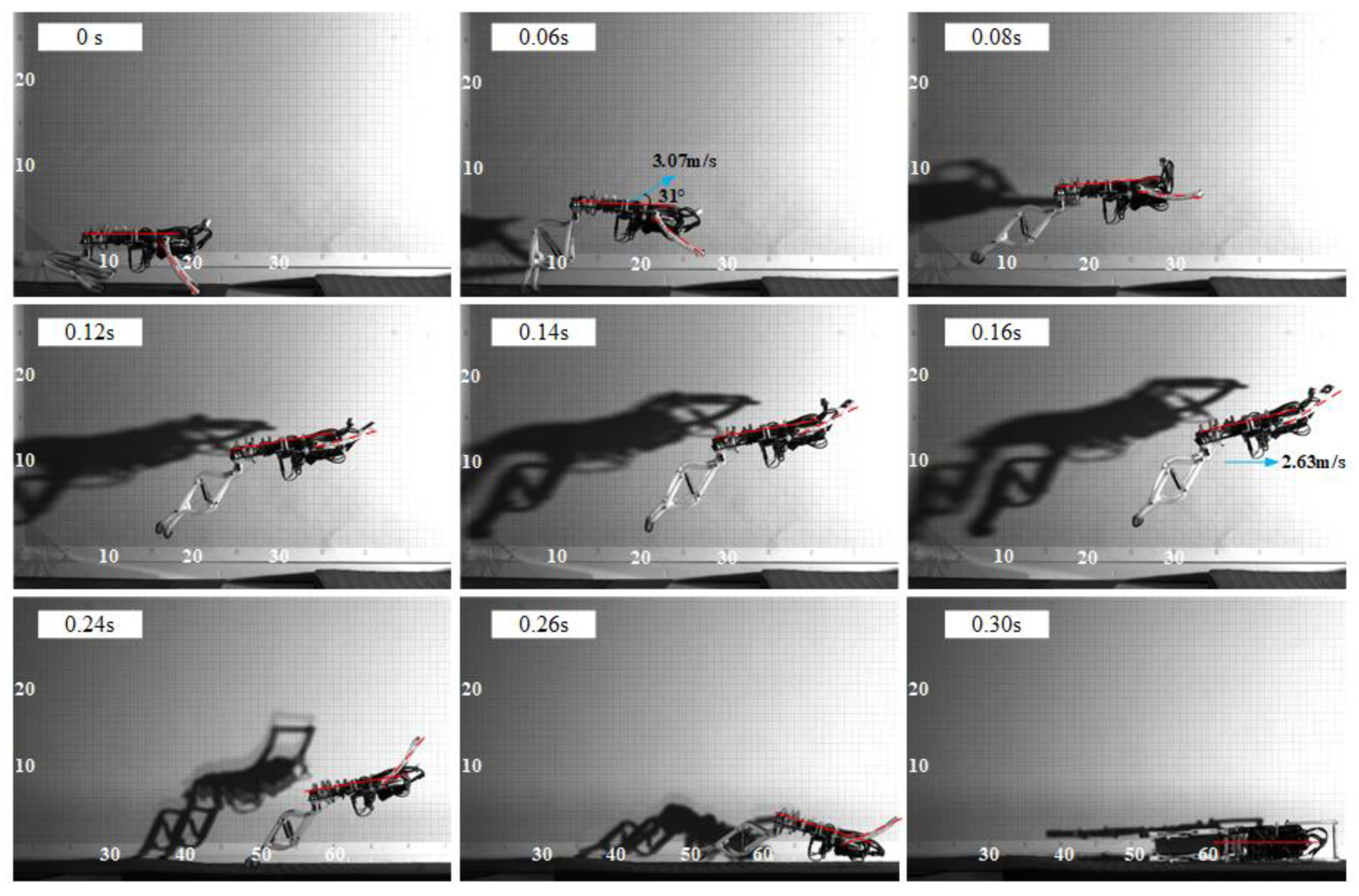
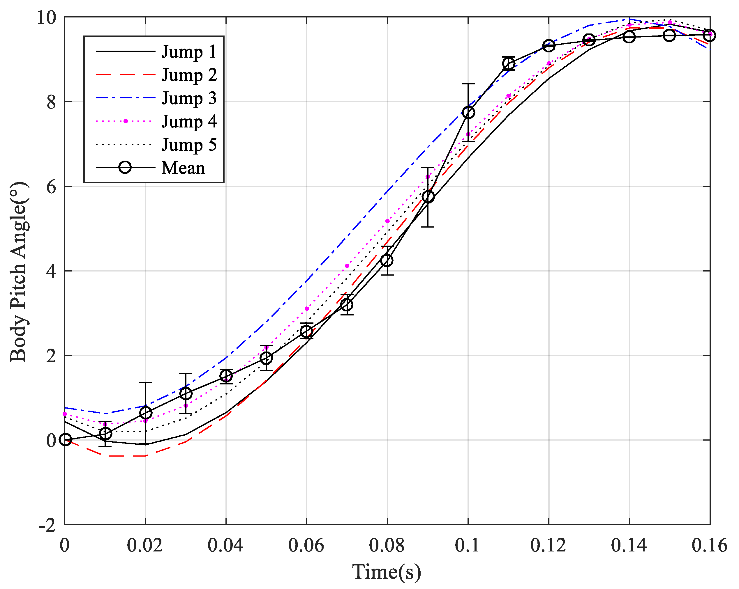
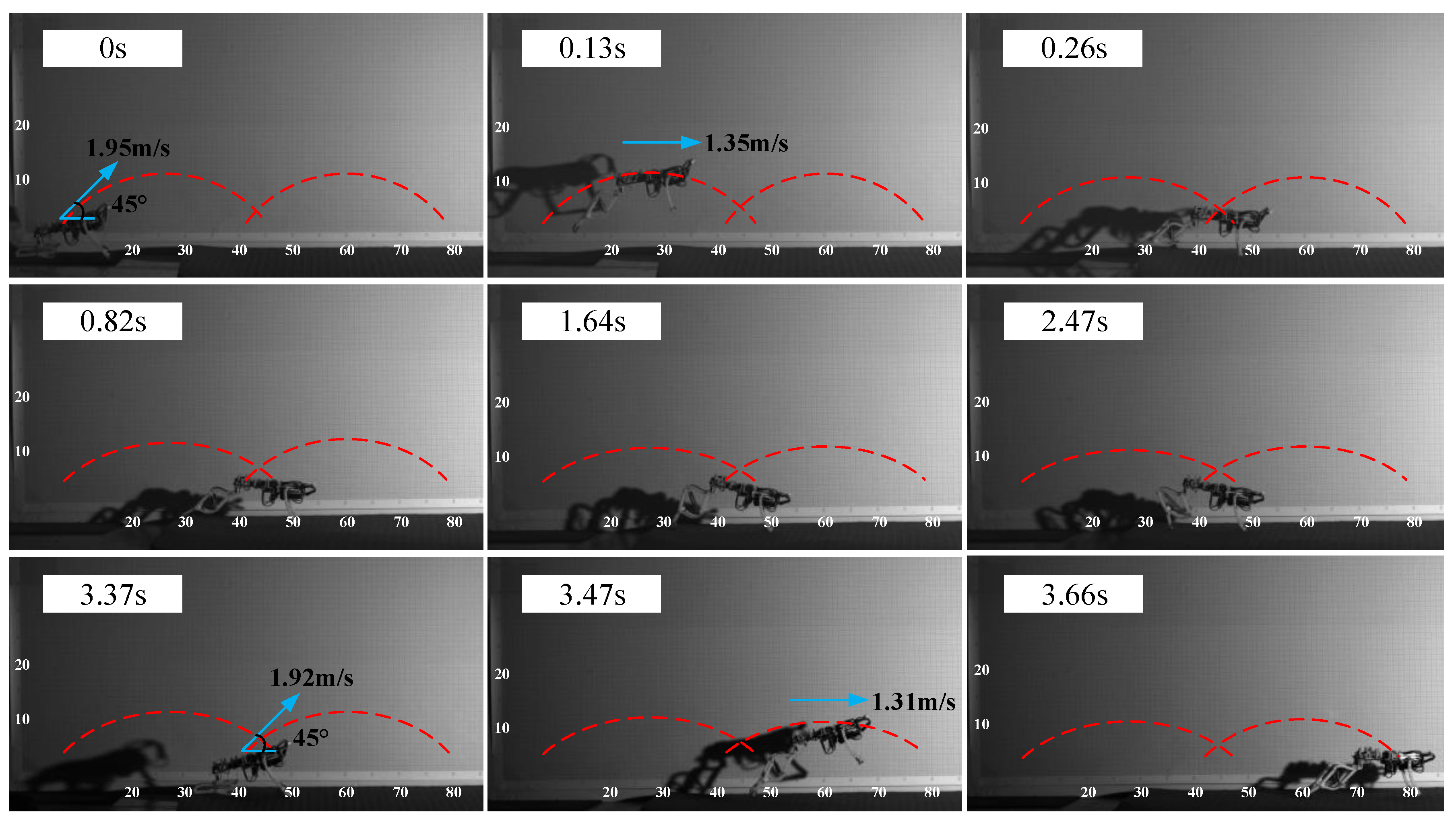
6.2.2. The Mode of Jumping for Progress

According to the workflow of the mode of jumping for progress, one turn of the pulley and 20° of the angle between the body and the ground were taken as the initial state before jumping. The motion sequence of two intermittent jumps is shown in Figure 27. It can be seen from Figure 27 that, the prototype leaves the ground with the velocity of 1.95 m/s and the takeoff angle of 45°; the prototype reaches the highest point of the jump trajectory at 0.13 s with the velocity of 1.35 m/s and the height of 10 cm; the prototype makes a smooth landing and completes its first jump at 0.26 s with a jump distance of 38 cm; the prototype enters the preparation stage for next jumping, and it began to drive the winding pulley to rotate and adjust the body posture at 0.82 s; the prototype starts the second jump with the same initial state at 3.37 s; the highest point of the second jump is reached at 3.47 s with the velocity of 1.31 m/s and the height of 9 cm; the prototype completes its second jump at 3.66 s with a jump distance of 36 cm. The total distance of the two jumps is 0.74 m, and the total time is 3.66 s, so the average progress speed is 0.2 m/s.

7. Conclusions

In this paper, we have presented the design, analysis, and experiment of a miniature jumping robot that mimics a flying squirrel and realizes two jumping modes with different takeoff speeds and stances by using a new spring charging and releasing mechanism.
According to the design goal of the robot, this paper analyzes the jump characteristics of flying squirrels in different modes and designs each part and workflow of the robot. Additionally, the requirement for aerial pitching posture of the robot after taking off is analyzed, and the dynamic model of adjusting the pitching by the swing of the forelimbs is established and simulated. Finally, a prototype is made and its performance is tested. From the results, the robot can takeoff at about 3 m/s and pitch angle of 0° in the mode of jumping for gliding, and adjust the pitch angle at the top to 0°~10° by actuating the forelimbs swing according to the requirement of gliding; in the mode of jumping for progress, the robot can takeoff at about 2 m/s and pitch angle of 20° and then intermittent jump with the distance of 0.37 m of once jump and the average progress speed of 0.2 m/s.
To the best of our knowledge, the robot presented in this paper is the first centimeter-scale bionic jumping robot that has the capabilities of changing the speeds and stances autonomically when takeoff. In the future work, we will further reduce the mass of the robot, increase the takeoff speed and the stability of the aerial posture, and integrate the wing membranes deployable mechanism to complete the design and development of the flexible wing-limb blending platform.

Author Contributions

Conceptualization, F.Z. and W.W.; methodology, F.Z.; software, F.Z.; validation, F.Z., J.W., and J.Z.; formal analysis, F.Z., J.W., and J.Z.; investigation, F.Z., W.D., and P.Z.; resources, W.W.; data curation, F.Z., W.D., and P.Z.; writing—original draft preparation, F.Z.; writing—review and editing, F.Z., W.W., and J.W.; visualization, F.Z.; supervision, W.W.; project administration, F.Z.; funding acquisition, W.W. All authors have read and agreed to the published version of the manuscript.

Funding

This research was supported by Beijing Natural Science Foundation (3202015) and the Academic Excellence Foundation of BUAA for PhD Students.

Institutional Review Board Statement

The flying squirrel used in this study follow the regulations for the Administration of Affairs Concerning Experimental Animals issued by the Institutional Animal Care and Use Committee of Beijing.

Conflicts of Interest

The authors declare no conflict of interest.

Appendix A

Table A1. Main parameters of gear system.
ParametersMotor GearGear 1Gear 2Transmission Gear
Number of teeth20402040
Module (mm)0.50.50.50.5
Pressure angle (°)20202020

References

  1. Tadokoro, S. Rescue Robotics: DDT Project on Robots and Systems for Urban Search and Rescue; Springer: London, UK, 2009. [Google Scholar]
  2. Nagatani, K.; Kiribayashi, S.; Okada, Y.; Otake, K.; Yoshida, K.; Tadokoro, S.; Nishimura, T.; Yoshida, T.; Koyanagi, E.; Fukushima, M.; et al. Emergency response to the nuclear accident at the Fukushima Daiichi Nuclear Power Plants using mobile rescue robots. J. Field Robot. 2012, 30, 44–63. [Google Scholar] [CrossRef]
  3. Armour, R.; Paskins, K.; Bowyer, A.; Vincent, J.; Megill, W. Jumping robots: A biomimetic solution to locomotion across rough terrain. Bioinspir. Biomim. 2007, 2, S65–S82. [Google Scholar] [CrossRef] [Green Version]
  4. Armour, R.H. A Biologically Inspired Jumping and Rolling Robot; University of Bath: Bath, UK, 2010. [Google Scholar]
  5. Desbiens, A.; Pope, M.; Berg, F. Efficient jumpgliding: Theoryand design considerations. In Proceedings of the IEEE International Conference on Robotics and Automation, Karlsruhe, Germany, 6–10 May 2013. [Google Scholar]
  6. Desbiens, A.L.; Pope, M.T.; Christensen, D.L.; Hawkes, E.W.; Cutkosky, M.R. Design principles for efficient, repeated jumpgliding. Bioinspir. Biomim. 2014, 9, 025009. [Google Scholar] [CrossRef] [PubMed]
  7. Kovac, M.; Hraiz, W.; Fauria, O.; Zufferey, J.-C.; Floreano, D. The EPFL jumpglider: A hybrid jumping and gliding robot with rigid or folding wings. In Proceedings of the 2011 IEEE International Conference on Robotics and Biomimetics, Karon Beach, Thailand, 7–11 December 2011; pp. 1503–1508. [Google Scholar]
  8. Vidyasagar, A.; Zufferey, J.; Floreano, D.; Kovač, M. Performance analysis of jump-gliding locomotion for miniature robotics. Bioinspir. Biomim. 2015, 10, 025006. [Google Scholar] [CrossRef] [PubMed]
  9. Kovac, M.; Fuchs, M.; Guignard, A.; Zufferey, J.-C.; Floreano, D. A miniature 7g jumping robot. In Proceedings of the 2008 IEEE International Conference on Robotics and Automation, Pasadena, CA, USA, 19–23 May 2008; pp. 373–378. [Google Scholar]
  10. Woodward, M.; Sitti, M. MultiMo-Bat: A biologically inspired integrated jumping–gliding robot. Int. J. Robot. Res. 2014, 33, 1511–1529. [Google Scholar] [CrossRef]
  11. Beck, A.; Hanan, M.Z. A Jumper-glider bio-robot inspired by the locust. Robotics 2016, 1. [Google Scholar] [CrossRef]
  12. Beck, A.; Zaitsev, V.; Ben Hanan, U.; Kosa, G.; Ayali, A.; Weiss, A. Jump stabilization and landing control by wing-spreading of a locust-inspired jumper. Bioinspir. Biomim. 2017, 12, 066006. [Google Scholar] [CrossRef]
  13. Zaytsev, V.; Gvirsman, O.; Hanan, U. A locust-inspired miniature jumping robot. Bioinspir. Biomim. 2015, 10, 66012. [Google Scholar] [CrossRef] [PubMed]
  14. Xiaojuan, M.; Wenjie, G.; Donglai, Z.; Dunwen, W. Review: Research Status of Miniature Jumping Robot. Chin. J. Mech. Eng. 2019, 55, 109–123. [Google Scholar] [CrossRef] [Green Version]
  15. Zhang, Z.; Zhao, J.; Chen, H.; Chen, D. A Survey of Bioinspired Jumping Robot: Takeoff, Air Posture Adjustment, and Landing Buffer. Appl. Bionics Biomech. 2017, 2017, 1–22. [Google Scholar] [CrossRef] [Green Version]
  16. Jungg, P.; Casarezc, S.; Jungs, P. An integrated jumping-crawling robot using height-adjustable jumping module. In Proceedings of the IEEE International Conference on Robotics and Automation, Stockholm, Sweden, 16–21 May 2016; pp. 4680–4685. [Google Scholar]
  17. Loepfe, M.; Schumacher, C.M.; Lustenberger, U.B. An untethered, jumping roly-poly soft robot driven by combustion. Soft Robot. 2015, 2, 33–41. [Google Scholar] [CrossRef]
  18. Hu, W.; Lum, G.Z.; Mastrangeli, M.; Sitti, M. Small-scale soft-bodied robot with multimodal locomotion. Nat. Cell Biol. 2018, 554, 81–85. [Google Scholar] [CrossRef]
  19. Sugiyama, Y.; Hirai, S. Crawling and Jumping by a Deformable Robot. Int. J. Robot. Res. 2006, 25, 603–620. [Google Scholar] [CrossRef]
  20. Chai, H.; Li, J.; Wenjie, G.E. Gait analysis on bionic kangaroo-hopping robot based on adjustable geared five-linkage mechanism. Robot 2009, 31, 487–492. [Google Scholar]
  21. Zhang, J.; Song, G.; Li, Y.; Qiao, G.; Song, A.; Wang, A. A bio-inspired jumping robot: Modeling, simulation, design, and experimental results. Mechatronics 2013, 23, 1123–1140. [Google Scholar] [CrossRef]
  22. Fiorini, P.; Burdick, J. The Development of Hopping Capabilities for Small Robots. Auton. Robot. 2003, 14, 239–254. [Google Scholar] [CrossRef]
  23. Miao, Z.; Mo, J.; Li, G.; Ning, Y.; Li, B. Wheeled hopping robot with combustion-powered actuator. Int. J. Adv. Robot. Syst. 2018, 15. [Google Scholar] [CrossRef]
  24. Libby, T.; Moore, T.Y.; Chang-Siu, E.; Li, D.; Cohen, D.J.; Jusufi, A.; Full, R.J. Tail-assisted pitch control in lizards, robots and dinosaurs. Nat. Cell Biol. 2012, 481, 181–184. [Google Scholar] [CrossRef]
  25. Zhao, J.; Zhao, T.; Xi, N.; Cintron, F.J.; Mutka, M.W.; Xiao, L. Controlling aerial maneuvering of a miniature jumping robot using its tail. In Proceedings of the 2013 IEEE/RSJ International Conference on Intelligent Robots and Systems, Tokyo, Japan, 3–7 November 2013; pp. 3802–3807. [Google Scholar]
  26. Zhao, J.; Zhao, T.; Xi, N.; Mutka, M.W.; Xiao, L. MSU Tailbot: Controlling Aerial Maneuver of a Miniature-Tailed Jumping Robot. IEEE/ASME Trans. Mechatron. 2015, 20, 2903–2914. [Google Scholar] [CrossRef]
  27. Liu, G.-H.; Lin, H.-Y.; Lin, H.-Y.; Chen, S.-T.; Lin, P.-C. A Bio-Inspired Hopping Kangaroo Robot with an Active Tail. J. Bionic Eng. 2014, 11, 541–555. [Google Scholar] [CrossRef]
  28. Essner, R.L. Three-dimensional launch kinematics in leaping, parachuting and gliding squirrels. J. Exp. Biol. 2002, 205, 2469–2477. [Google Scholar]
  29. Stafford, B.J.; Thorington, R.W.; Kawamichi, T. Positional behavior of Japanese giant flying squirrels (Petaurista leucogenys). J. Mammal. 2003, 84, 263–271. [Google Scholar] [CrossRef]
  30. Thorington, R.W.; Darrow, K.; Anderson, C.G. Wing Tip Anatomy and Aerodynamics in Flying Squirrels. J. Mammal. 1998, 79, 245–250. [Google Scholar] [CrossRef] [Green Version]
  31. Socha, J.J.; Jafari, F.; Munk, Y.; Byrnes, G. How animals glide: From trajectory to morphology. Can. J. Zool. 2015, 93, 901–924. [Google Scholar] [CrossRef]
  32. Ando, M.; Shiraishi, S. Gliding Flight in the Japanese giant flying squirrel Petaurista leucogenys. J. Mammal. Soc. Jpn. 1993, 18, 19–32. [Google Scholar]
  33. Vernes, K. Gliding performance of the northern flying squirrel (Glaucomys sabrinus) in mature mixed forest of eastern Canada. J. Mammal. 2001, 82, 1026–1033. [Google Scholar] [CrossRef] [Green Version]
  34. Bishop, K.L. The relationship between 3-D kinematics and gliding performance in the southern flying squirrel, Glaucomys volans. J. Exp. Biol. 2006, 209, 689–701. [Google Scholar] [CrossRef] [PubMed] [Green Version]
  35. Bahlman, J.W.; Swartz, S.M.; Riskin, D.K.; Breuer, K.S. Glide performance and aerodynamics of non-equilibrium glides in northern flying squirrels (Glaucomys sabrinus). J. R. Soc. Interface 2013, 10, 20120794. [Google Scholar] [CrossRef] [Green Version]
  36. Yeaton, I.J.; Socha, J.J.; Ross, S.D. Global dynamics of non-equilibrium gliding in animals. Bioinspir. Biomim. 2017, 12, 026013. [Google Scholar] [CrossRef] [Green Version]
  37. Paskins, K.E.; Bowyer, A.; Megill, W.M. Take-off and landing forces and the evolution of controlled gliding in northern flying squirrels Glaucomys sabrinus. J. Exp. Biol. 2007, 210, 1413–1423. [Google Scholar] [CrossRef] [Green Version]
  38. Chickering, J.G.; Sokoloff, A.J. Innervation of propatagial musculature in a flying squirrel, Glaucomys volans (Rodentia, Sciuridae). Brain Behav. Evol. 1996, 47, 1–7. [Google Scholar] [CrossRef] [PubMed]
  39. Jackson, S.M. Glide angle in the genus Petaurus and a review of gliding in mammals. Mammal Rev. 2000, 30, 9–30. [Google Scholar] [CrossRef]
  40. Wang, Y.; Feng, B.; Yin, L. Research on Jumping Mechanism and Bionic Design Based on Characteristics of Squirrel Leg. Mech. Res. Appl. 2018, 31, 158–162. [Google Scholar]
  41. Tangler, J.L.; Kocurek, J.D. Wind Turbine Post-Stall Airfoil Performance Characteristics Guidelines for Blade-Element Mo-mentum Methods. Power 2005, 1–10. [Google Scholar] [CrossRef] [Green Version]
  42. Zhao, F.; Wang, W.; Zhang, J.; Wyrwa, J.; Sun, F. Aerodynamic Characteristics and Pitching Adjusting Mechanism of the Flying Squirrel with Deployed Patagium. IEEE Access 2019, 7, 185554–185564. [Google Scholar] [CrossRef]
  43. Shampine, L.F.; Gladwell, I.; Thompson, S. Solving ODEs with Matlab; Cambridge University Press: Cambridge, UK, 2003. [Google Scholar]
Figure 1. Structural form of flexible wing–limb blending platform.
Applsci 11 03362 g001
Figure 2. Locomotion conceiving of flexible wing–limb blending platform.
Applsci 11 03362 g002
Figure 3. Motional sequence of jumping for gliding of the flying squirrel. The white dots are the markers on the joints of the hind limb, and the red lines denote the linkages between the joints.
Applsci 11 03362 g003
Figure 4. Motional sequence of jumping for progress of the flying squirrel. The white dots are the markers on the joints of the hind limb, and the red lines denote the linkages between the joints.
Applsci 11 03362 g004
Figure 5. Physiological structure of hind limbs of flying squirrels.
Applsci 11 03362 g005
Figure 6. Schematic of joints of hind limbs of flying squirrel.
Applsci 11 03362 g006
Figure 7. Angles of each joint of the flying squirrel’s hind limbs when jumping for gliding.
Applsci 11 03362 g007
Figure 8. Angles of each joint of the flying squirrel’s hind limbs when jumping for progress.
Applsci 11 03362 g008
Figure 9. Schematic of structure of hind limbs.
Applsci 11 03362 g009
Figure 10. 3D model of hind limbs of the robot.
Applsci 11 03362 g010
Figure 11. Composition and principle of the mechanism of loading and releasing of spring. (a) Overall structure; (b) loading; (c) releasing.
Applsci 11 03362 g011
Figure 12. The transmission system.
Applsci 11 03362 g012
Figure 13. The relation between the motor’s torque and the angle β 3 .
Applsci 11 03362 g013
Figure 14. 3D model of the overall structure of the robot.
Applsci 11 03362 g014
Figure 15. Workflow of the robot.
Applsci 11 03362 g015
Figure 16. Trajectory of the end of the hind limbs when loading.
Applsci 11 03362 g016
Figure 17. Forces on the robot when gliding.
Applsci 11 03362 g017
Figure 18. Simulation results for gliding trajectory.
Applsci 11 03362 g018
Figure 19. Schematic of the robot after takeoff for dynamics modeling of pitching adjustment.
Applsci 11 03362 g019
Figure 20. Simulation results for pitching adjustment under different states of forelimbs.
Applsci 11 03362 g020
Figure 21. Simulation results for pitching adjustment under different angular speeds of forelimbs.
Applsci 11 03362 g021
Figure 22. Prototype of the jumping robot inspired by flying squirrels. (a) The robot at fully flexed position; (b) the robot at fully extended position.
Applsci 11 03362 g022
Figure 23. Motion sequence of jumping for gliding when the forelimbs are not actuated. The solid red lines denote the body, the dotted red lines denote the forelimbs, and the blue arrows denote the direction of velocity.
Applsci 11 03362 g023
Figure 24. Motion sequence of jumping for gliding when the forelimbs are actuated. The solid red lines denote the body, the dotted red lines denote the forelimbs, and the blue arrows denote the direction of velocity.
Applsci 11 03362 g024
Figure 25. Experimental results for pitching adjustment when the forelimbs are not actuated.
Applsci 11 03362 g025
Figure 26. Experimental results for pitching adjustment when the forelimbs are actuated.
Applsci 11 03362 g026
Figure 27. Motion sequence of jumping for progress. The dotted red lines denote jumping trajectory, and the blue arrows denote the direction of velocity.
Applsci 11 03362 g027
Table 1. MATLAB simulation parameters.
ParametersValueParametersValue
m B 0.07 kg m L 0.01 kg
l B C 0.03 m l A C 0.06 m
J B 6.3 × 10⁻⁵ kg·m2 J L 3.6 × 10⁻⁵ kg·m2
τ s 0.15 N·m ω 0 600 deg/s
L O 8.5 × 10⁻⁴ kg·m2/s ϕ B ( 0 )
θ B L ( 0 ) 90° ϕ L ( 0 ) −90°
Table 2. Materials and weights of the prototype components.
ComponentsMaterialWeight (gr)
Body frameCarbon fiber13
Cam, Gears, BracketsPhotosensitive resin10.5
Transmission shaftAluminum alloy4.2
LimbsPhotosensitive resin14
SpringsSteel2.1
Controller and sensors-17.2
Motors-12
Battery-10
Total weight 83
Publisher’s Note: MDPI stays neutral with regard to jurisdictional claims in published maps and institutional affiliations.

