1. Introduction
Adaptive gripping is one of the main areas of soft robotics applications [
1]. Soft gripping, in which the gripper adapts to differently shaped objects, is in great demand in unknown or dynamically changing environments [
2]. Their properties enable the gripping and manipulation of objects of various shapes, while their softness and flexibility allow them to manipulate even fragile objects. As a result, they find their application not only in industrial robotics, such as the automotive industry [
3], but especially in service robotics, where they can be used, for example, in the food industry to collect fragile crops whose shapes and sizes vary [
1,
4], or in the home environment for handling objects of various shapes (such as keys, pens, mugs, etc.) [
5,
6].
There are several possible principles for solving such grippers. For example, pneumatic 3D printed soft grippers that change shape according to internal pressure [
7], vacuum soft grippers [
8], soft and shape adaptive electroadhesive grippers [
9,
10], shape adaptive and reversible magnetorheological elastomer-based grippers [
11], and electrically controlled soft 3D printed hand shearing auxetics grippers [
12].
This work is focused on gripers with passively adaptive structures using the Fin Ray effect [
4]. This effect is based on the biomechanical principles of fish fins [
13]. After pressing the object on the FinRay finger, the finger flexibly wraps around it [
1]. This effect is used not only for gripping objects [
14,
15] but can also be used, for example, for locomotion of a robot in water [
16]. Due to their shape and necessary mechanical properties, 3D printing from flexible materials is mainly used for their production [
4]. Since 2016, company Festo has been offering three differently sized types of these fingers [
17]. Several studies have already been conducted on Fin Ray structures. Some of them dealt with the dependence of the gripping force on the deformation of the finger when changing the internal geometry and filling [
4,
13,
18], or deal with mathematical models [
1] or simulation [
1,
19]. Some works evaluate the suitability of given fingers only for deformation at the point of contact according to the load [
4,
13]. Other work [
15] evaluate the suitability only for the maximum deformation at the endpoint of the finger. However, the measurement at a single point is insufficient to describe the wrapping of the finger around the object. So far, however, no specific way has been determined to evaluate the proposed finger regarding its ability to wrap around the object.
This work comes up with a new and simple way to mathematically evaluate the finger’s wrapping around the object by measuring two dimensions. This work aim is not to find the overall most optimal finger structure that can exist but to describe a new method by which it will be possible to easily compare variants of different structures and find the optimal one between them. Several internal structures were created for testing, in which their specific parameters were changing. Basic testing takes place in a simulation program for creating nonlinear analyzes. Based on the simulations results and the evaluation method, the most suitable finger structures were printed by the Fused Filament Fabrication method, and their mechanical properties verified on a real test device. The results of this work are intended to make it easier for designers to assess their designed fingers from the point of view of wrapping their finger around the object. They also can use graphs from the results of this work and determine the finger’s dimensions without the inner filling according to the required force and deflection.
2. Materials and Methods
2.1. Finger Evaluation Methodology
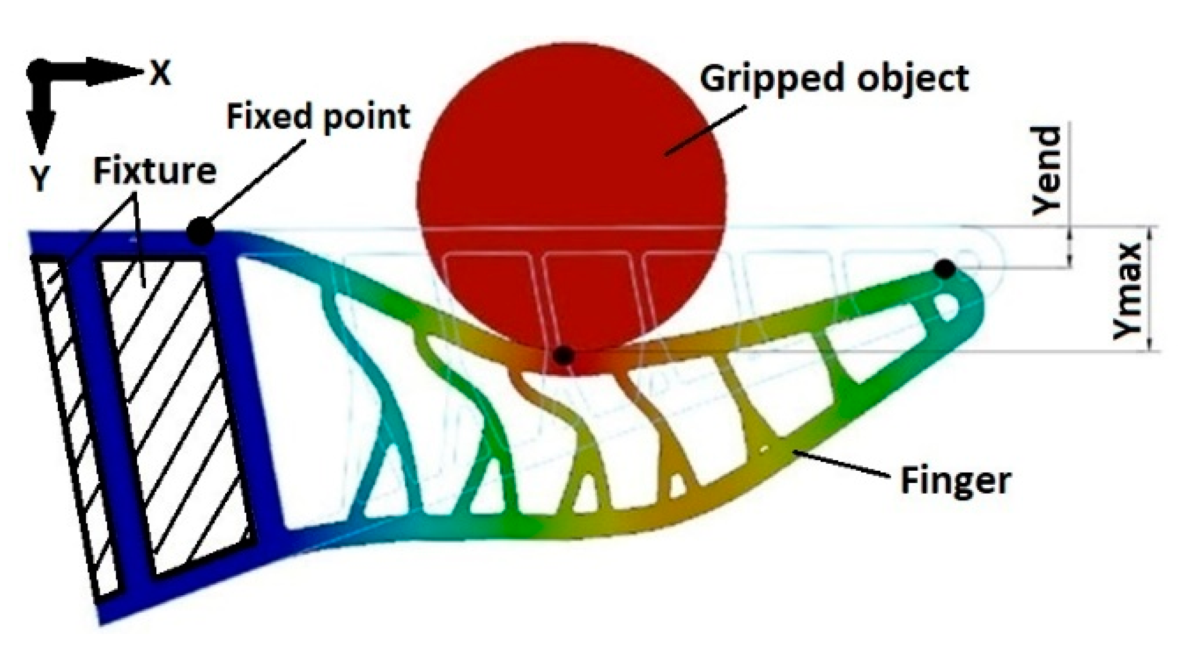
The evaluation of individual finger variants is based on their behaviour under load. The finger is constrained by a fixture on one side, and the gripped object is then pressed into the finger. To find out if the finger has wrapped around the gripped object, it is necessary to know the positions of at least three points. The first point is a contact point between the gripper and the gripped object. The second one is positioned before the first one in the direction towards finger’s fixed base, and the third one in the opposite direction towards finger’s tip. Positions of these three points on the finger can be easily measured. The position at the beginning of the finger does not change under load due to a fixed fixture. The maximum deflection appears at the point of contact. These three positions are on the finger’s contact edge, and they are sufficient to describe the wrapping of the finger around the gripped object. Since the position at the beginning (fixed point) of the finger does not change, it is unnecessary to measure it. The positions of the remaining two points change under load and are defined by the distance by which the points move perpendicular to the contact surface in the unloaded state.
Figure 1 shows these measured distances, where Ymax is the maximum deflection value and Yend is the value of the deflection at the fingertip.
Yend and Ymax values were determined at each millimeter of compression. The millimeter step is chosen because of the different internal structures; the ratio of these values may differ depending on the magnitude of the deformation. From these values, the total finger deflection coefficient Ψ is calculated according to the following formula:
where
is the deflection coefficient,
is the distance of the endpoint in the
i-th millimeter of compression,
is the maximum deflection of the finger in the
i-th millimeter of compression, which is equal to the depth of compression of the steel roller into the finger in millimeters, n is the maximum depth of compression, which is 8 mm. The value of the maximum deflection of the finger 8 mm was determined based on the previous simulations of these sizes of fingers, in which there were failures of the simulations because of buckling in some tested structures at a greater value of deflection. There could be a different value of maximum deflection for another size, shape, or inner structure of the fingers.
The smaller the deflection coefficient, the more finger’s shape wraps around the manipulated object. Therefore, the most suitable type of finger is the one whose deflection coefficient Ψ is the smallest.
2.2. Tested Filling Patterns Structures
The patterns testing was based on the shape of an existing Festo finger [
17], on a study of works already performed, and expert judgment. Various finger parameters were tested, such as the thickness of selected walls, the number of ribs, and the change in the geometry of the internal structure in which branching occurs, which is based on real fish fins [
20]. According to aim of this paper, selected testing structures and parameters are not chosen to find the overall most optimal structure that can even exist but to compare the different structures and find the optimal by applying the new methodology.
Figure 2 shows the basic test structures of the fingers.
The thickness of all fingers is 15 mm, with a side length of 61 mm. The radius of the fingertip curvature is 2.5 mm, and the opening angle is 20° (as shown in structure A). In structure A, four parameters are changing. The wall thicknesses TF and TB, the thickness of the inner ribs TR, and the number of ribs. The default values of these thicknesses is 1.6 mm, with only one selected thickness always changing and the rest remaining at the default value. The structure B has no internal filling, and values of thicknesses TF and TB are changing. These values are always equal, and, thus, both change simultaneously (the finger is always symmetrical). Structure C is an example of a branched structure where the inner rib in the middle of the jaw branches into two at an angle of 30°. The thickness TR1 and TR2 changes. The structure D is also branched, but its branching is shifted to the left side (side to the contact surface concerning the object of manipulation) by 2 mm. The structure E is similar, but its branching is shifted by 2 mm to the opposite side. The parameters of the structures D and E change in the same way as for the structure C, and all branched structures were loaded both to the contact side and to the opposite side. All combinations of test fingers are shown in the
Table 1, with some parameters listed referring to the figure above. The values of the different thicknesses of the parameters are graduated in 0.4 mm increments, based on the printer nozzle diameter on which the selected fingers is printed.
A total of 46 different fingers variants were tested.
2.3. Loading of the Testing Finger
A steel roller with a diameter of 20 mm and a length of 25 mm was pressed into the finger. It acts perpendicular to the contact surface in the middle of the finger, which, according to Festo [
17], is the most suitable area for gripping handling objects. In the testing of the finger, this grip area is located 25 mm from its tip, as shown in the
Figure 3.
Three ways of loading the finger were simulated. In the first method, the roller was pressed into the finger to a depth of 8 mm. At each millimeter of compression, the maximal deflection values (point of contact of the finger with the cylinder) and deflection of the fingertip were measured. These values were used to calculate the deflection coefficient according to which the most suitable structure was selected from all tested.
In the second test, the steel roller was pressed this time not to the required distance but by force of 5 N, while the deformation of the entire contact surface of the finger was measured. This force value was chosen with respect to the structures used to minimize the number of variations of the fingers, which would reach irreversible deformation. This case occurred with a single variation of the finger, namely the structure B for the thickness TF = TB 1.6 mm, where the simulation stopped with the message that the solution may be in the buckling or at the limit point, i.e., the displacements increase at constant forces. This test is done only to prove that the simulations at a constant load of 5 N are not suitable for the selection of the finger shape based on its suitability from the point of view of wrapping the fingers around the object, as examined by some previously performed works [
4,
13].
The third method is only valid for selected types of fingers when compared with real tests. With this method, the roller load force is gradually increased until the finger bends at the point of contact by 8 mm. The deflection of the point of contact is measured to display a graph of the dependence of this deflection on the applied forces.
2.4. Basic Simulation Settings
All finger simulations were performed as nonlinear simulations in SOLIDWORKS 2019 [
21] software. Due to the finger’s constant cross-section across its entire width, 2D Simplification was used to simplify the computational model and thus shorten the computational time. The finger material was set as hyperelastic Mooney Rivlin model, and the values from the tensile curve were used to set its parameters, as described in the following chapter. The Roller material is steel. The finger is rigidly attached to the edges on one side. A No Penetration contact bond is set between the edges of the Steel Roller and the Finger. Automatic Solver Selection is set for the analysis.
Figure 4 shows the finger attachment and the points for the measurement.
For the simulation to determine the deflection coefficient, the Stell roller is set to move in the positive Y-axis direction by a distance of 8 mm. X-axis movement is prohibited. The deflections of the points Ymax and Yend are measured at each mm of the steel roller movement.
For the simulation applied a force of 5 N is applied to the Steel roller in the positive Y-axis direction, where the Steel roller is allowed to move. In the X-axis, the movement of the roller is again prohibited. In this simulation, the entire contact edge deflection is measured, which is further shown in the graphs.
When simulating selected types of internal finger structures for comparison with real measurements, the force is gradually increased (for each finger separately) until the Ymax is deflected by approximately 8 mm.
2.5. Finger Material
Fingers and samples are printed from Fiberflex TPU 30D [
22]. It is a flexible material whose hardness value is according to the Shore 30D scale and is currently one of the softest materials for FFF printers on the market [
23]. Printing took place on the Original Prusa i3 MK3S printer [
24] with a modified Flexion extruder [
25] for printing flexible materials. The G-code for the printer was generated using PrusaSlicer v2.3 software [
26]. The basic printing parameters are shown in the
Table 2.
2.6. Material Settings for Simulation
Due to the fact that the tested material TPU 30D is not in the standard offer of materials for simulation, the possibility of software to set the properties of this material by uploading the Stress–stretch ratio curve from a tensile test to the simulation software was used. Samples, according to ISO 527, were printed for the tensile test [
27]. The dimensions of the sample are shown in
Figure 5.
The samples were tested for tensile test on a Testometric M500/50 CT machine [
28]. The test specimens failed to break even at the maximum unloading of the machine. According to the filament manufacturer catalogue [
22], the material can stretch by up to 900%.
Figure 6 shows its extension. On the left is the sample before the test, and on the right during the test.
For the required purpose, the sample did not need to break, because the elastic deformation took place to a strain of about 25%, and then plastic deformations began to appear. For the simulation, it was necessary to obtain the stress dependence on the stretch ratio from the tensile curve, which is calculated according to the following formula:
where
is the stretch ratio,
is the final length, and
is the initial length. The
Figure 7 shows the stress dependence of the stretch ratio for the TPU 30D material.
2.7. Real Testing
Since real fingers are most often made using 3D printing [
4,
13,
16,
18], a test is performed to compare simulated material behaviour concerning real printed fingers. According to the simulations results, the most suitable types of fingers were printed and tested on a test device. An industrial robot ABB IRB 1600 [
29] with ABB Small force sensor [
30] was used for testing. This assembly makes it possible to measure the force magnitude up to 495 N with an accuracy of 0.11 N, while the positioning accuracy is 0.02 mm [
29,
30]. The setup of the real experiment is shown in the
Figure 8.
The test finger is firmly attached to a stand that is screwed to the worktop. The robot moves the roller to the required position 2 mm above the contact surface. It is then moved at a speed of 0.1 mm/s perpendicular to the contact surface to a depth of 10 mm (the finger deflection is thus 8 mm). This testing measures the dependence of the deformation on the loading force. In the same way, a simulation is created for selected fingers for mutual comparison. The results of this test assess the difference between the simulated and real behaviour of the fingers. On the other hand, the results can help designers design selected fingers according to the required force and deflection.
2.8. Demonstration of Grasping Various Objects
Several selected variants of fingers (based on simulations) were used to grip selected objects to prove the fingers suitability for gripping objects of various shapes. Selected items are a lighter, a cube (which will be gripped first by its side and then by one edge) with a side size of 20 mm, an egg (which will be gripped first of its longest sides, the second time around its circumference) and a car bulb, which will be grasped by its metal sleeve. The items are shown in
Figure 9.
3. Results
This chapter describes the results obtained during the simulations of individual variants of structures to determine the deflection coefficient and thus evaluate the most suitable structure from the point of view of wrapping around the object. Furthermore, the simulation results of individual variations of structures under load with a constant force of 5 N are presented. Some selected types of fingers are also printed and tested on a real device while also compared with simulations to verify the simulated finger behaviour to the real one. Finally, a demonstration of grasping various objects with selected fingers is showed.
3.1. Simulations
In the first set of simulations, all finger variations were tested for deflection coefficient. Out of all the tested structures, the smallest deflection coefficients were measured for structure B, i.e., a finger without an internal structure. The best result was obtained on the variation of this structure with a wall thickness of 2.8 mm, whose deflection coefficient is equal to 0.27. The second best result was achieved on structure A with the number of ribs 6, namely, the value 0.42. Of the branched structures, structures E performed best when loaded towards the contact side with the same thicknesses TR1 = TR2 = 0.8 mm, for which the value of the deflection coefficient is 0.44. The load towards the opposite side at the same wall thicknesses TR1 = TR2 = 0.8 mm, for which the value of the deflection coefficient is 0.46. Based on these results, for which printing and comparison with real testing were selected, fingers from the structure B at wall thicknesses of 1.6 mm, 2.8 mm, and 4 mm, fingers from the structure A with the number of ribs six, and the two branched structures E, which achieved the best deflection values coefficients.
Table 3 lists all the tested fingers and their calculated deflection coefficients. The table also contains the ranking, representing the order of the most advantageous fingers in terms of deflection coefficient. If more than one tested finger has the same deflection coefficient value, they have the same ranking value.
When simulating structures for which their parameters changed, i.e., structures A and B, the deformation was dependent on the changed parameter. The lower the value of this parameter, the greater the deformation, as shown in the
Figure 10, where the deformation’s dependence on the distance of the contact surface from the fixed region for structure B under load 5 N is shown.
Due to the deformation’s dependence on the given parameters’ size, only graphs of the largest and lowest deformations for each structure and its changed parameter are used to compare all structures in
Figure 11. Of the branched structures, only the structures are shown that achieved the greatest and the smallest deformation.
From the figure, it is evident that the finger with one rib reached the greatest deformation. Nevertheless, from the deflection coefficient point of view, this finger is only in the 10th place. The finger of structure B with a wall thickness of 4 mm has reached three, the smallest deformations, yet according to the deflection coefficient 6, it is the best of all. From these results, it is clear that the amount of deflection at constant load is not a suitable parameter for assessing the fingers from the point of view of their wrapping around the gripped object.
Due to the fact that for branched structures, not only one parameter changed, but also their shape, the individual results are shown separately in
Figure 12.
3.2. Real Testing
For real testing, fingers were selected from the group with the lowest deflection coefficient, i.e., fingers without internal structure (structure B). A total of three fingers were tested, with a minimum wall thickness of 1.6 mm, a maximum wall thickness of 4 mm and a mean value of 2.8 mm. Furthermore, a sample with six ribs, branched structure E at the same thickness was tested, both under load from the contact surface and under load to the opposite side.
During real testing, the dependence of the deformation at the point of contact on the applied force was determined.
Figure 13 shows this dependence of all selected structures when measured, while the values measured on a real device are compared with simulations.
Figure 13 shows that the simulations are very close to the results of real testing. The simulated behaviour of the material can therefore be considered to correspond to the real behaviour. When the wall thickness of structure B (parameters TF and TB) increases, so do the force required for the given deflection.
Figure 14 shows the deformed finger in the simulation compared to the real testing with the structure B and the wall thickness of 1.6, 2.8, and 4 mm.
Figure 15 shows the deformed finger in the simulation in comparison with the real testing with the structure E mark 5 and 11, and the structure A with the number of ribs six.
For possible application, it is appropriate to point out the hysteresis of flexible materials. For the printed finger, the hysteresis gave a different dependence of deformations on the applied force depending on whether the object was pushed towards the finger (loaded) or was moved away from the finger (unloading). This hysteresis also varies according to the number of load cycles. A total of 500 load cycles were used for this testing.
Figure 16 shows the cyclic hysteresis with different loading and unloading values and for different cycles for a finger with structure B with a wall thickness of 2.8 mm.
The results show the deformation dependence at the place of loading on the loaded force according to the number of load cycles. As the number of cycles increases, the amount of force required to induce a certain amount of deformation decreases.
Figure 17 shows the results from real testing of structures B and structure A with six ribs. The number of load cycles of each finger tested is 500.
3.3. Demonstration of Grasping Various Objects
For grasping demonstration, fingers were selected from the group with the lowest deflection coefficient, i.e., fingers without internal structure (Structure B with a wall thickness of 1.6 mm and 4 mm) and for comparison the structure A with six ribs. The
Figure 18 demonstrates their grip with selected objects.
4. Discussion
This work comes up with a new and simple method of evaluating the finger wrapping around the object mathematically. Several types of internal structures have been designed, in which their parameters, such as the thickness of the selected walls or the number of internal ribs have changed. To evaluate the wrapping of the finger around the object, a method was determined that measures the ratio between the deflection of the endpoint and the maximum deflection of the finger. Tensile test data was used to set up the material for simulation analysis properly. The tested material is TPU 30D. It is a flexible filament designed for printing on Fused Filament Fabrication printers. The pressed object is a steel roller with a diameter of 20 mm.
Three tasks were chosen for the simulation. In the first simulation, the roller is pressed into the finger 8 mm to the depth. Based on the results of this simulation, the deflection coefficients are calculated. In the second simulation, the roller is pressed into the finger with a force of 5 N. The simulation illustrates and points out that from the point of view of wrapping the finger around the object, the magnitude of deformation after loading with a certain force is not very appropriate, as examined by some previously performed works [
4,
13]. The third method is done only for few selected types of fingers to compare them with real tests. With this method, the roller load force is gradually increased until the finger bends at the point of contact by 8 mm. The deflection of the point of contact is measured to display a graph of this deflection’s dependence on the applied forces. Graphs showing the hysteresis of the printed fingers of structures B and structure A with six ribs were also measured and shown for designers possible needs. Selected finger variations were chosen to demonstrate their ability to grasp various objects. All the selected structures were able to grasp all the selected objects and their contact sides wrapped around their shape appropriately.
From the analyses results, it is evident that the greatest wrapping of the fingers around the object occurs in the types of fingers without an internal structure (structure B). For all structures, the dependence between individual parameters (for example, the thickness of selected walls or the number of inner ribs) on the deflection at a constant force was observed. The simulations were verified on selected types of fingers printed on a 3D printer and tested on a real test device.
A comparison of the calculated deflection coefficients from the first set of simulations and deformation caused by constant force of 5 N from the second set of tests revealed that the amount of deflection at constant load is not a suitable parameter for judging fingers view of their wrapping around the object.
The work aimed not to find the most suitable structure that can exist or include all possible structure variants. The aim was to find a methodology for comparing different structures with each other according to their ability to wrap around a wrapped object. This methodology can be used to test other variants of fingers, changes in their other parameters, sizes, and shapes, etc.
This work aims to serve the designers in comparing the FinRay finger structures to find the maximum finger wrap around the gripped objects. For the selected structures in this paper, the work shows graphs of deformation dependence on the gripping force for individual parameters of structures (for example, wall thickness), which could be useful for the designers of the fingers.
Author Contributions
Conceptualization, J.S., Z.B. and M.V.; methodology, J.S.; software, J.M., M.V. and P.O.; validation, J.S., Z.B. and Z.Z.; formal analysis, J.S.; investigation, Z.Z.; resources, J.S.; data curation, Z.Z.; writing—original draft preparation, J.S.; writing—review and editing, Z.Z.; visualization, J.S.; supervision, Z.B.; project administration, Z.B.; funding acquisition, Z.B. All authors have read and agreed to the published version of the manuscript.
Funding
This article has been elaborated under support of the project Research Centre of Advanced Mechatronic Systems, reg. no. CZ.02.1.01/0.0/0.0/16_019/0000867 in the frame of the Operational Program Research, Development and Education. This article has been also supported by specific research project SP2021/47 and financed by the state budget of the Czech Republic.
Institutional Review Board Statement
Not applicable.
Informed Consent Statement
Not applicable.
Data Availability Statement
The data presented in this study are available on request from the corresponding author. The data are not publicly available due to project restrictions.
Conflicts of Interest
The authors declare no conflict of interest.
References
- Shan, X.; Birglen, L. Modeling and analysis of soft robotic fingers using the fin ray effect. Int. J. Robot. Res. 2020, 39, 1686–1705. [Google Scholar] [CrossRef]
- Elgeneidy, K.; Fansa, A.; Hussain, I.; Goher, K. Structural Optimization of Adaptive Soft Fin Ray Fingers with Variable Stiffening Capability. In Proceedings of the 2020 3rd IEEE International Conference on Soft Robotics (RoboSoft), New Haven, CT, USA, 15 May–15 July 2020; IEEE: Piscataway, NJ, USA, 2020. [Google Scholar]
- MultiChoiceGripper. Available online: https://www.festo.com/net/SupportPortal/Files/333986/Festo_MultiChoiceGripper_en.pdf (accessed on 5 March 2021).
- Elgeneidy, K.; Lightbody, P.; Pearson, S.; Neumann, G. Characterising 3D-printed Soft Fin Ray Robotic Fingers with Layer Jamming Capability for Delicate Grasping. In Proceedings of the 2019 2nd IEEE International Conference on Soft Robotics (RoboSoft), Seoul, Korea, 14–18 April 2019; IEEE: Piscataway, NJ, USA, 2020. [Google Scholar]
- Fischinger, D.; Einramhof, P.; Papoutsakis, K.; Wohlkinger, W.; Mayer, P.; Panek, P.; Hofmann, S.; Koertner, T.; Weiss, A.; Argyros, A.; et al. Hobbit, a care robot supporting independent living at home: First prototype and lessons learned. Robot. Auton. Syst. 2016, 75, 60–78. [Google Scholar] [CrossRef]
- Stückler, J.; Steffens, R.; Holz, D.; Behnke, S. Efficient 3D object perception and grasp planning for mobile manipulation in domestic environments. Robot. Auton. Syst. 2013, 61, 1106–1115. [Google Scholar] [CrossRef]
- Zhang, H.; Kumar, A.S.; Fuh, J.Y.H.; Wang, M.Y. Design and Development of a Topology-Optimized Three-Dimensional Printed Soft Gripper. Soft Robot. 2018, 5, 650–661. [Google Scholar] [CrossRef] [PubMed]
- Li, H.; Yao, J.; Wie, C.; Zhou, P.; Xu, Z.; Zhao, Y. An untethered soft robotic gripper with high payload-to-weight ratio. Mech. Mach. Theory 2021, 158, 104226. [Google Scholar] [CrossRef]
- Guo, J.; Xiang, C.; Zanini, P.; Rossiter, J. Magnetic Augmented Self-sensing Flexible Electroadhesive Grippers. IEEE Roboti. Autom. Lett. 2019, 4, 2364–2369. [Google Scholar] [CrossRef] [Green Version]
- Guo, J.; Xiang, C.; Rossiter, J. A soft and shape-adaptive electroadhesive composite gripper with proprioceptive and exteroceptive capabilities. Mater. Design 2018, 156, 586–587. [Google Scholar] [CrossRef]
- Choi, D.S.; Kim, T.H.; Lee, S.H.; Pang, C.; Bae, J.W.; Kim, S.Y. Beyond Human Hand: Shape-Adaptive and Reversible Magnetorheological Elastomer-Based Robot Gripper Skin. ACS Appl. Mater. Interfaces 2020, 12, 44147–44155. [Google Scholar] [CrossRef] [PubMed]
- Truby, R.L.; Chin, L.; Rus, D. A Recipe for Electrically-Driven Soft Robots via 3D Printed Handed Shearing Auxetics. IEEE Robot. Autom. Lett. 2021, 6, 795–802. [Google Scholar] [CrossRef]
- Basson, C.I.; Bright, G. Geometric Conformity Study of a Fin Ray Gripper Utilizing Active Haptic Control. In Proceedings of the 2019 IEEE 15th International Conference on Control and Automation (ICCA), Edinburgh, UK, 16–19 July 2019; IEEE: Piscataway, NJ, USA, 2019. [Google Scholar]
- Pfaff, O.; Simeonov, S.; Cirovic, I.; Stano, P. Application of finray effect approach for production process automation. In Proceedings of the Annals of DAAAM and Proceedings of the International DAAAM Symposium, Vienna, Austria, 23–26 November 2011; Danube Adria Association for Automation and Manufacturing, DAAAM: Wien, Austria. [Google Scholar]
- Crooks, W.; Vukasin, G.; O’Sullivan, M.; Messner, W.; Rogers, C. Fin Ray® Effect Inspired Soft Robotic Gripper: From the RoboSoft Grand Challenge toward Optimization. Front. Robot. AI 2016, 3, 2296–9144. [Google Scholar] [CrossRef]
- Gatto, V.L.; Rossiter, J.M.; Hauser, H. Robotic Jellyfish Actuated by Soft FinRay Effect Structured Tentacles. In Proceedings of the 2020 3rd IEEE International Conference on Soft Robotics (RoboSoft), New Haven, CT, USA, 15 May–15 July 2020; IEEE: Piscataway, NJ, USA, 2020. [Google Scholar]
- Adaptive Gripper Fingers DHAS. Available online: https://www.festo.com/cat/en-gb_gb/data/doc_ENGB/PDF/EN/DHAS_EN.PDF (accessed on 5 March 2021).
- Lee, L.Y.; Nurzaman, S.G.; Tan, C.P. Design and Analysis of a Gripper with Interchangeable Soft Fingers for Ungrounded Mobile Robots. In Proceedings of the 2019 IEEE International Conference on Cybernetics and Intelligent Systems (CIS) and IEEE Conference on Robotics, Automation and Mechatronics (RAM), Bangkok, Thailand, 18–20 November 2019; IEEE: Piscataway, NJ, USA, 2020. [Google Scholar]
- Ali, M.H.; Zhanabayev, A.; Khamzhin, A.; Mussin, K. Biologically Inspired Gripper Based on the Fin Ray Effect. Proceedings of 2019 5th International Conference on Control, Automation and Robotics (ICCAR), Beijing, China, 19–22 April 2019; Danube Adria Association for Automation and Manufacturing, DAAAM: Wien, Austria; IEEE: Piscataway, NJ, USA, 2020. [Google Scholar]
- Aiello, B.R.; Hardy, A.R.; Cherian, C.; Olsen, A.M.; Ahn, S.E.; Hale, M.E.; Westneat, M.W. The relationship between pectoral fin ray stiffness and swimming behavior in Labridae: insights into design, performance and ecology. J. Exp. Biol. 2018, 221, 1–10. [Google Scholar] [CrossRef] [PubMed] [Green Version]
- Dassault Systems. Available online: https://www.solidworks.com/product/solidworks-3d-cad (accessed on 5 March 2021).
- Technical Data Sheet Fiberflex 30D. Available online: https://www.materialpro3d.cz/user/related_files/tds_fiberflex_30d_en.pdf (accessed on 5 March 2021).
- Flexible Filament. Available online: https://www.3dprintcz.cz/flexible-filament (accessed on 5 March 2021).
- Original Prusa i3 MK3S 3D Printer. Available online: https://shop.prusa3d.com/en/3d-printers/181-original-prusa-i3-mk3s-3d-printer.html (accessed on 5 March 2021).
- Single Flexion Retrofit Kit for Single Extruder. Available online: https://flexionextruder.com/shop/single (accessed on 5 March 2021).
- PrusaSlicer 2.3. Available online: https://www.prusa3d.com/prusaslicer/#_ga=2.96407198.300644305.1591643943-1493863876.1591643943 (accessed on 5 March 2021).
- ISO 527-1:2019. Plastics—Determination of Tensile Properties—Part 1: General Principles; IOS: Geneva, Switzerland, 2019. [Google Scholar]
- Testometric. Available online: https://www.testometric.co.uk/50kn (accessed on 5 March 2021).
- Technical Data for the IRB 1600 Industrial Robot. Available online: https://new.abb.com/products/robotics/industrial-robots/irb-1600/irb-1600-data (accessed on 5 March 2021).
- Product Manual Integrated Force Control. Available online: https://abb.sluzba.cz/Pages/Public/IRC5UserDocumentationRW6/en/3HAC048488%20PM%20Integrated%20Force%20Control-en.pdf (accessed on 5 March 2021).
Figure 1.
Measured distances on finger.
Figure 1.
Measured distances on finger.
Figure 2.
Filling patterns structure: (A) Straight ribs; (B) No internal filling; (C) Branched ribs with branching in the middle; (D) Branched ribs with branching shifted to the left side; (E) Branched ribs with branching shifted to the right side.
Figure 2.
Filling patterns structure: (A) Straight ribs; (B) No internal filling; (C) Branched ribs with branching in the middle; (D) Branched ribs with branching shifted to the left side; (E) Branched ribs with branching shifted to the right side.
Figure 3.
Loading of the testing finger.
Figure 3.
Loading of the testing finger.
Figure 4.
Simulated assembly.
Figure 4.
Simulated assembly.
Figure 5.
Sample dimensions for tensile test.
Figure 5.
Sample dimensions for tensile test.
Figure 6.
Test sample. Left: before loading, right: during the test.
Figure 6.
Test sample. Left: before loading, right: during the test.
Figure 7.
Stress dependence on the stretch ratio for material TPU 30D.
Figure 7.
Stress dependence on the stretch ratio for material TPU 30D.
Figure 8.
Testing device. Left: entire device, right: detail under load.
Figure 8.
Testing device. Left: entire device, right: detail under load.
Figure 9.
Items for grasping.
Figure 9.
Items for grasping.
Figure 10.
Fingers’ contact side deformation of the variants of structures B under load 5 N.
Figure 10.
Fingers’ contact side deformation of the variants of structures B under load 5 N.
Figure 11.
Comparison of all structures according to deformation under load 5 N.
Figure 11.
Comparison of all structures according to deformation under load 5 N.
Figure 12.
Deformation of the contact side for structures C, D, and E under load 5 N.
Figure 12.
Deformation of the contact side for structures C, D, and E under load 5 N.
Figure 13.
Dependence of loading force on deformation for finger without filling for simulated and real tests.
Figure 13.
Dependence of loading force on deformation for finger without filling for simulated and real tests.
Figure 14.
Comparison of the simulation with the printed tested finger of structure B, left: simulation, right: real test, top: wall thickness 1.6 mm, middle: wall thickness 2.8 mm, bottom: wall thickness 4 mm.
Figure 14.
Comparison of the simulation with the printed tested finger of structure B, left: simulation, right: real test, top: wall thickness 1.6 mm, middle: wall thickness 2.8 mm, bottom: wall thickness 4 mm.
Figure 15.
Comparison of the simulation with the printed tested finger, left: simulation, right: real test; top: structure E mark EO0808, middle: structure E mark EC0808, bottom: structure A with the number of ribs 6.
Figure 15.
Comparison of the simulation with the printed tested finger, left: simulation, right: real test; top: structure E mark EO0808, middle: structure E mark EC0808, bottom: structure A with the number of ribs 6.
Figure 16.
Hysteresis for structure B with a wall thickness of 2.8 mm.
Figure 16.
Hysteresis for structure B with a wall thickness of 2.8 mm.
Figure 17.
Cyclic hysteresis for tested structures B and structure A with 6 ribs.
Figure 17.
Cyclic hysteresis for tested structures B and structure A with 6 ribs.
Figure 18.
Demonstration of grasping various objects. Structures: left column—Structure B with a wall thickness of 1.6 mm; middle column—structure A with the number of ribs 6; right column—Structure B with a wall thickness of 4 mm.
Figure 18.
Demonstration of grasping various objects. Structures: left column—Structure B with a wall thickness of 1.6 mm; middle column—structure A with the number of ribs 6; right column—Structure B with a wall thickness of 4 mm.
Table 1.
Parameters of tested fingers.
Table 1.
Parameters of tested fingers.
| Parameter | Structure | Dimension | Value |
|---|
| Contact side thickness | A | TF | 1.6–4 mm |
| Opposite side thickness | A | TB | 1.6–4 mm |
| Rib thickness | A | TR | 0.8–2 mm |
| Number of ribs | A | - | 1–9 |
| Without inner fill | B | TF = TB | 1.6–4 mm |
| Branching, direction to the contact edge | C | TR1, TR2 | 1.6; 2 mm |
| Branching, direction from the contact edge | C | TR1,TR2 | 1.6; 2 mm |
| Branching, shifted from the center towards the contact surface | C,D | TR1, TR2 | 1.6; 2 mm |
| Branching, shifted from the center away from the contact surface | C,E | TR1,TR2 | 1.6; 2 mm |
Table 2.
Basic parameters of printer settings.
Table 2.
Basic parameters of printer settings.
| Parameter | Value |
|---|
| Filament diameter | 1.75 mm |
| Nozzle diameter | 0.4 mm |
| Layer height | 0.2 mm |
| Infill | 100% |
| Number of perimeters | 10 |
| Nozzle temperature | 210 °C |
| Bed temperature | 60 °C |
| Perimeter speed | 45 mm/s |
| Speed for infill | 80 mm/s |
| Speed for first layer | 20 mm/s |
| Speed for top layer | 40 mm/s |
Table 3.
Deflection coefficient for testing structures.
Table 3.
Deflection coefficient for testing structures.
| Structure | Additional
Information | Changed Parameter | Marking for Graph | Deflection
Coefficient Ψ (-) | Ranking |
|---|
| A | Contact side thickness TF | TF = 1.6 mm | A TF 1.6 mm | 0.46 | 11 |
| TF = 2 mm | | 0.48 | 13 |
| TF = 2.4 mm | | 0.52 | 17 |
| TF = 2.8 mm | | 0.55 | 19 |
| TF = 3.2 mm | | 0.59 | 22 |
| TF = 3.6 mm | | 0.61 | 23 |
| TF = 4 mm | A TF 4 mm | 0.62 | 24 |
| Opposite side thickness TB | TB = 1.6 mm | A TB 1.6 mm | 0.46 | 11 |
| TB = 2 mm | | 0.47 | 12 |
| TB = 2.4 mm | | 0.49 | 14 |
| TB = 2.8 mm | | 0.51 | 16 |
| TB = 3.2 mm | | 0.53 | 18 |
| TB = 3.6 mm | | 0.56 | 20 |
| TB = 4 mm | A TB 4 mm | 0.59 | 22 |
| Rib thickness TR | TR = 0.8 mm | A TR 0.8 mm | 0.44 | 9 |
| TR = 1.2 mm | | 0.45 | 10 |
| TR = 1.6 mm | | 0.5 | 15 |
| TR = 2 mm | A TR 2 mm | 0.59 | 22 |
| Number of ribs | 1 | A 1 rib | 0.45 | 10 |
| 2 | | 0.43 | 8 |
| 3 | | 0.44 | 9 |
| 4 | | 0.43 | 8 |
| 5 | | 0.45 | 10 |
| 6 | A 6 ribs | 0.42 | 7 |
| 7 | | 0.46 | 11 |
| 8 | | 0.44 | 9 |
| 9 | A 9 ribs | 0.46 | 11 |
| B | Thickness of
contact and
opposite side
TF = TB | TF = TB = 1.6 mm | B TF = TB 1.6 mm | 0.31 | 5 |
| TF = TB = 2 mm | B TF = TB 2 mm | 0.30 | 4 |
| TF = TB = 2.4 mm | B TF = TB 2.4 mm | 0.28 | 2 |
| TF = TB = 2.8 mm | B TF = TB 2.8 mm | 0.27 | 1 |
| TF = TB = 3.2 mm | B TF = TB 3.2 mm | 0.28 | 2 |
| TF = TB = 3.6 mm | B TF = TB 3.6 mm | 0.29 | 3 |
| TF = TB = 4 mm | B TF = TB 4 mm | 0.32 | 6 |
| C | Load towards the contact side | TR1 = TR2 = 0.8 mm | CC0808 | 0.47 | 12 |
| TR1 = 0.8 mm; TR2 = 1.2 mm | CC0812 | 0.52 | 17 |
| Load towards the opposite side | TR1 = TR2 = 0.8 mm | CO0808 | 0.5 | 15 |
| TR1 = 0.8 mm; TR2 = 1.2 mm | CO0812 | 0.57 | 21 |
| D | Load towards the contact side | TR1 = TR2 = 0.8 mm | DC0808 | 0.51 | 16 |
| TR1 = 0.8 mm; TR2 = 1.2 mm | DC0812 | 0.57 | 21 |
| Load towards the opposite side | TR1 = TR2 = 0.8 mm | DO0808 | 0.51 | 16 |
| TR1 = 0.8 mm; TR2 = 1.2 mm | DO0812 | 0.5 | 15 |
| E | Load towards the contact side | TR1 = TR2 = 0.8 mm | EC0808 | 0.44 | 9 |
| TR1 = 0.8 mm; TR2 = 1.2 mm | EO0812 | 0.48 | 13 |
| Load towards the opposite side | TR1 = TR2 = 0.8 mm | EO0808 | 0.46 | 11 |
| TR1 = 0.8 mm; TR2 = 1.2 mm | EO0812 | 0.59 | 22 |
| Publisher’s Note: MDPI stays neutral with regard to jurisdictional claims in published maps and institutional affiliations. |
© 2021 by the authors. Licensee MDPI, Basel, Switzerland. This article is an open access article distributed under the terms and conditions of the Creative Commons Attribution (CC BY) license (https://creativecommons.org/licenses/by/4.0/).


