Abstract
The turbine blade is a key component in an aeroengine. Currently, measuring the turbine blade radiation temperature always requires obtaining the emissivity of the target surface in advance. However, changes in the emissivity and the reflected ambient radiation cause large errors in measurement results. In this paper, a three-wavelength radiation temperature measurement method was developed, without known emissivity, for reflection correction. Firstly, a three-dimensional dynamic reflection model of the turbine blade was established to describe the ambient radiation of the target blade based on the real surface of the engine turbine blade. Secondly, based on the reflection correction model, a three-wavelength radiation temperature measurement algorithm, independent of surface emissivity, was proposed to improve the measurement accuracy of the turbine blade radiation temperature in the engine. Finally, an experimental platform was built to verify the temperature measurement method. Compared with three conventional colorimetric methods, this method achieved an improved performance on blade temperature measurement, demonstrating a decline in the maximum error from 6.09% to 2.13% and in the average error from 2.82% to 1.20%. The proposed method would benefit the accuracy in the high-temperature measurement of turbine blades.
1. Introduction
Turbine blades are key components of aeroengines. In order to improve engine performance and reduce fuel consumption, turbine blades are usually required to work at the highest possible temperature. However, the blades could be damaged if the operation temperature exceeds its limit, greatly reducing their service life. Accurate temperature measurement of turbine blades prevents them from operating at excessively high temperatures and can be helpful in blade diagnosis as well [1,2]. Therefore, temperature measurement of turbine blades is of great significance to the safe operation of aeroengines. The high-temperature and high-pressure working environment of turbine blades, combined with the high-speed rotation, limit the application of contact-type temperature measurement. Therefore, radiation temperature measurement has been widely used in the field of the temperature measurement of engine turbine blades [3,4,5,6,7]. However, this type of measurement faces significant challenges. As the target blade reflects ambient radiation, and the reflection is mainly from the adjacent blades, this results in a significant error in radiation temperature measurement. Additionally, the emissivity of the target blade is challenging to be accurately obtained because it varies with blade oxidation and temperature; this leads to difficulties in radiation temperature measurement.
Researchers have adopted a variety of methods to reduce the effects of reflected radiation during radiation temperature measurement. Suarez-Gonzalez and Oqlukian [8] proposed an iterative calculation of triple spectral area thermometry to correct for the reflection effect of turbine blades. Shu et al. [9] established a rotary kiln temperature field model to compensate for the effects of target surface reflection and atmospheric absorption during radiation temperature measurement. Fu et al. [10] obtained the reflected ambient radiation energy by placing a cooled standard plate on the measurement sample, eliminating reflected radiation. Lü et al. [11] eliminated the effects of reflected radiation on the target surface by calibrating the thermometer at different ambient temperatures. Hernandez et al. [12] used the solar blind method to estimate the influence of solar radiation on the atmospheric absorption band, which then reduced the temperature measurement error caused by the reflection of solar radiation from the target. Lucia and Lanfranchi [13] proposed a calculation method for the radiation angle factor of a fixed-position turbine blade based on a simplified two-dimensional shape. Gao et al. [14] improved this method by replacing the rotation with the translation of a simplified two-dimensional shape blade, calculating the radiation angle factor of the turbine blade at different positions, and correcting for the reflection effect using the actual temperature of the adjacent blade.
For the problem of unknown emissivity of the target surface, the current mainstream solution is to use a multi-wavelength temperature measurement algorithm to obtain the true temperature of the target surface with unknown emissivity using a specific emissivity model. Sun et al. [15] proposed a six-wavelength radiation pyrometer to measure the temperature of molten metals. Khatami and Levendis [16] proposed two three-wavelength radiation thermometry methods to measure the surface temperature of burning carbon particles. Madura et al. [17] proposed an emissivity compensation algorithm for three-wavelength temperature measurement. Fu et al. [18] proposed a fast fiber-optic multi-wavelength pyrometer, which used a preset emissivity model to measure the target temperature. Sade and Katzir [19] proposed a passive measurement method of infrared spectral emissivity and temperature of materials, measuring the emissivity and temperature of two different objects.
In the radiation temperature measurement of a turbine blade, due to its complex shape, inevitable measurement errors can be induced by a two-dimensional model to analyze the ambient radiation shielded by other blades. Therefore, when correcting for the reflection effect of the target blade and analyzing its reflected radiation, it is necessary to consider its actual shape and to establish a three-dimensional rotating dynamic reflection model of the blade. As the main source of reflection, adjacent blades receive radiation from other adjacent blades and the target blade. Therefore, in the calculation and correction of adjacent blade radiation, the reflected energy on the surface of adjacent blades should be considered. To solve the above problems, this paper proposes a three-wavelength radiation temperature measurement method for turbine blades based on reflected radiation error correction. Firstly, a three-dimensional rotating dynamic reflection model of turbine blades based on discrete surface elements is established. Secondly, a reflection correction method based on measuring the total radiant exitance of adjacent blades is proposed. Thirdly, this paper also proposes a three-wavelength radiation temperature measurement algorithm based on reflection error correction. This algorithm does not require an emissivity model. Combined with the reflection correction method, it can eliminate the influence of reflection and retrieve the true temperature of the target blade without obtaining the emissivity of the adjacent blade and the target blade. Finally, an experiment is designed to verify the method proposed in this paper. The analysis in this paper provides a reference for radiation temperature measurement of turbine blades with unknown emissivity.
2. Theoretical Analysis of Reflection Error Correction for Ambient Radiation of Turbine Blade
2.1. Ambient Radiation Analysis of Turbine Blades
Figure 1 shows a schematic cross-sectional view of an arrangement of turbine engine blades. When the engine is started, the high-pressure gas generated in the combustion chamber passes backwards through the various guide vanes and rotor blades in turn. The guide vanes are fixed, and the rotor blades rotate at high speed around the axis of the engine driven by the gas. Among them, the first-stage rotor blades are most likely to be damaged because of the high temperature and high-speed rotation. This paper studies the reflection and temperature inversion of the trailing edge of the suction surface of the rotor blade measured by the radiation pyrometer probe in Figure 1. The main reflection sources are the adjacent guide vanes and the upper rotor blade. Radiation from these adjacent blades to the target blade was calculated. The low radiation from the casing wall was ignored due to the low temperature.
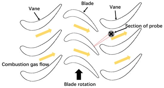
Figure 1.
Schematic diagram of engine turbine blade distribution and infrared pyrometer probe temperature measurement.
According to Planck’s law, the radiant emittance of an object whose temperature is higher than 0 K to the surrounding space is expressed as
where is the radiant emittance of a blackbody with temperature T at wavelength λ, c1 = 3.7418 × 10⁸ W μm4/m2 is the first radiation constant, and c2 = 1.4388 × 104 μm K is the second radiation constant.
Under the influence of reflection, the total radiant emittance of a point on the surface of the target blade, , should include the heat radiation of the target point itself and the reflection of ambient radiation and is expressed by
where is the irradiance of the target point radiated by the surrounding environment and is the emissivity of the target blade. For opaque surfaces, the sum of the emissivity and the reflectivity is 1.
A reflection model was established to analyze the radiation propagating from the adjacent blades to the target blade. Figure 2 shows the principle of the reflection model of a discretized blade. The adjacent blade is divided into many small panels, and the radiation angle factor of each panel is calculated. When considering the effect of reflection (or ambient radiation), Mtotal can also be expressed as [20]
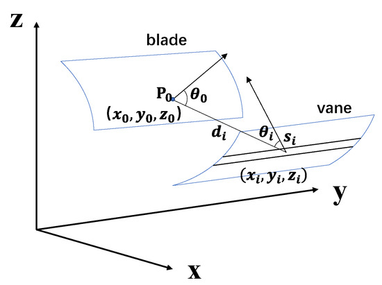
Figure 2.
Schematic diagram of the reflection relationship of discretized blade panel.
In Equation (3), is the total radiant exitance of the i-th panel on the adjacent blade, and is the radiation angle factor between panel i and the target point. Combined with the total radiant emittance of the adjacent blade surface, the radiation illuminance of the adjacent blade to the target blade can be calculated to correct for the reflection error of the target blade. To accurately calculate the radiation angle factor, it is necessary to establish a geometric model of the turbine blade in a three-dimensional space according to the actual shape of the turbine blade.
2.2. Three-Dimensional Dynamic Reflection Model of Turbine Blades
By establishing a coordinate transformation relationship of the turbine blade surface at different positions, the coordinates of each point on the blade surface at different positions can be described. Using the actual shape of an engine blade, a three-dimensional geometric model of a turbine blade was established. As shown in Figure 3, the x-axis is the engine axis, the rotor blades rotate around this axis, and the y-axis is parallel to the initial state rotor blade axis line r. The z-axis direction is determined by the right-hand rule. When the rotor blade rotates, line r rotates onto line r′, and the angle φ between the two straight lines represents the position angle of the rotor blade. A three-dimensional model of the rotor blade at φ = 0 was established, and the transformation relationship between the coordinates of each point on the rotor blade and φ was analyzed. First, we intercepted the blades with a set of planes parallel to the plane formed by the x-z axis with a certain step length and fit these intercept lines to obtain a set of equations:
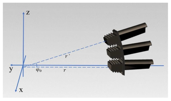
Figure 3.
Position changes of rotor blades at different angles.
Then, we analyzed the coordinate change of any point on the rotor blade section line in Figure 3 when it rotates. When the rotor blade rotates to the position angle , the y-axis coordinate of the point becomes
The x-axis coordinate of the point will not change during the rotation, and the z-axis coordinate will become
By obtaining the position coordinates of each point on the cross-section of the rotor blade, a geometric model of the rotor blade at any position angle φ can be established. The method of modeling the guide vane is the same as that of the rotor blade.
The established blade model was divided into panels, and the radiation angle factor of each panel was calculated. In order to ensure calculation accuracy, we divided the suction surface and pressure surface of all blades for analysis. Considering the calculation accuracy and speed comprehensively, we divided the suction surface and pressure surface of each blade into 9720 panels. The three-dimensional geometric model of the turbine blades is shown in Figure 4. According to the relative position of the turbine blades, the suction surface of the target blade, and the suction surface and pressure surface of the upper rotor blade, three adjacent guide vanes were modeled and discretized.
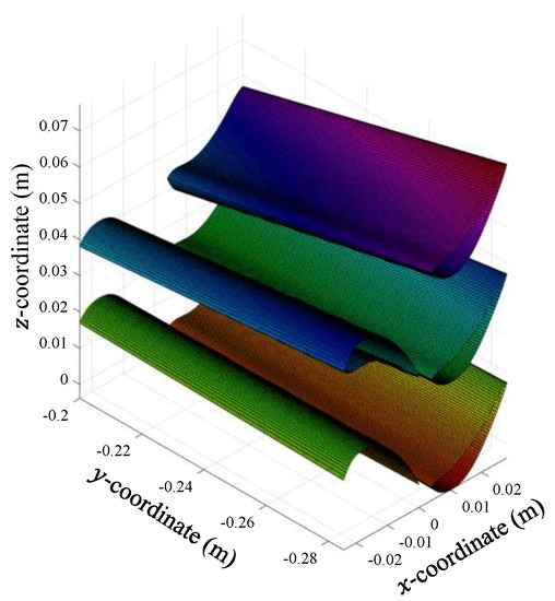
Figure 4.
The three-dimensional geometric model of the turbine blades.
A guide vane near the target blade was selected to analyze the radiation angle factor between each panel on the guide vane and the center point of the panel on the target blade. When the segmentation is sufficiently fine, each panel can be approximated as a rectangle, and the three-dimensional coordinates of all panel endpoints on the guide vane obtained by the geometric model can be expressed as matrices . As shown in Figure 5, the position vector and the length vector and width vector of the end point (for the element in the matrix) of a panel on the guide vane can be expressed as
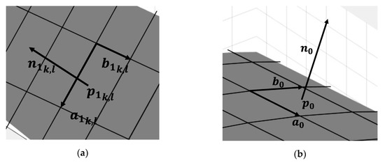
Figure 5.
Schematic diagram of face element vector of: (a) guide vane; (b) target blade.
The unit normal vector of the panel should be perpendicular to the vector and satisfy the right-hand rule, and the normal vector of the panel should point to the outside of the blade to calculate the angle factor. The unit normal vector is expressed as
The area of the panel is
The cosine of the angle between the direction vector from the panel to the target point and the normal vector of the panel is expressed as
The cosine of the angle between the direction vector from the target point to the panel and the normal vector of the target point is
where ; and are the direction vectors between the panel and the target point , and the two vectors are in opposite directions. The angle factor between a panel on the guide vane and the target point can be expressed as
Then, the angle factor of the entire guide vane to the target point is
Equation (15) was used to calculate the radiation angle factor between all the adjacent blades and a certain point on the target blade to obtain the radiation angle factor distribution of the whole target blade. Combined with the measured total radiation emittance of the adjacent blades, the reflected energy of the target blade surface can be calculated.
2.3. Simulation Results and Analysis of Dynamic Reflection Model
Based on the geometric models of the suction surface of the target blade, the suction surface and the pressure surface of the upper rotor blade, and the adjacent three guide vanes in Figure 4, the ambient radiation reflected by the trailing edge of the suction surface of the target blade is analyzed. First, the radiation angle factors between the three guide vanes and point shown in Figure 6 are calculated. Equation (15) is used to calculate the radiation angle factor of the adjacent blades to the target blade at different angles φ. In order to judge whether radiation can reach the target blade, the radiation angle of the panel and whether other blades block the panel radiation are considered in the calculation. Figure 6 illustrates the change in radiation propagating from the adjacent blades to point on the target blade when the target blade rotates and uses different colored shadows to distinguish the radiation propagating from different adjacent blades to on the target blade. The guide vanes are distributed periodically; therefore, we take the process of rotating the blade from the position to another position as a cycle, as shown in Figure 6a–c, and use the reflection model for analysis. The target blade rotates 6 degrees in one cycle. Figure 7 shows the simulation results of the reflection model; that is, the angle factor distribution between the target blade and guide vanes 1, 2, and 3 at different angles (φ = 0°, 2°, 4°, and 6°). In Figure 7, the x-axis is close to the trailing edge of the blade, and its positive direction is from the tip to the root of the blade. The y-axis is close to the tip, and its positive direction is from the trailing edge to the leading edge.
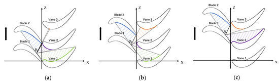
Figure 6.
Changes in radiation propagating from adjacent blades to point when the target blade moves at (a) φ = 0°, (b) φ = 3°, and (c) φ = 6°.
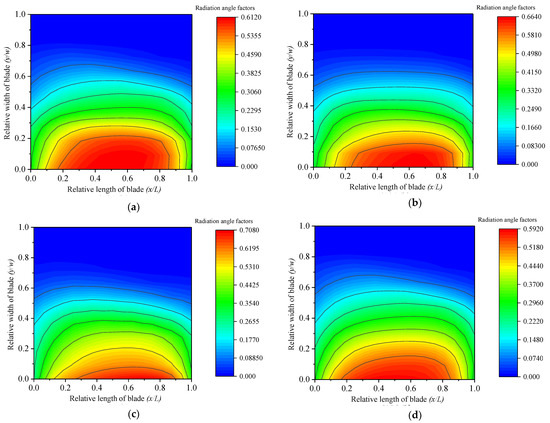
Figure 7.
Angular factor distribution between the target blade suction surface and the guide vane at different positions and angles of (a) φ = 0°, (b) φ = 2°, (c) φ = 4°, and (d) φ = 6°.
Figure 7 shows that during rotation of the target blade, the position where the most intense radiation from the three guide vanes is received is the trailing edge of the target blade suction surface. This is because the distance between the guide vanes and the trailing edge is the smallest compared with other parts of the target blade suction surface. However, due to the shape of the target blade and the shielding of the upper rotor blade, the radiation of the three guide vanes cannot reach the leading edge of the suction surface of the target blade, so the radiation angle factor is almost zero.
As shown in Figure 6, the relative position, between blade 2 and the target blade, does not change with the rotation of the target blade. Therefore, the angle factor distribution between the target blade and blade 2 is only related to the blade shape. The calculation result of the radiation angle factor of blade 2 is shown in Figure 8.
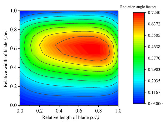
Figure 8.
Angular factor distribution between the target blade and blade 2.
The peak of the radiation angle factor between rotor blade 2 and the target blade is located near the protrusion of the blade surface. As rotor blades 1 and 2 are arranged at a certain angle in the engine, the peak position of the radiation angle factor deviates to the root side of the target blade at the protrusion of the suction surface.
According to the above simulation results, the reflected radiation and temperature measurement error of the target blade are simulated and calculated. The relative position coordinates of point are (0.5, 0.66), the target blade temperature is 1100 K, the guide vane temperature is 1000 K, the upper rotor blade temperature is the same as the target blade temperature, the target blade emissivity is 0.58, and the wavelength of radiation temperature measurement is 1550 nm. The ratio of the reflected energy on the surface of the target blade to the total energy received by the radiation pyrometer and the temperature measurement error caused by reflection are calculated. The relationship between them and the angle of the target blade is shown in Figure 9a. The energy reflected from the target blade to the adjacent blades account for more than 25% of the actual energy received by the radiation pyrometer, so the temperature measurement error exceeds 40 K. Moreover, the proportion of reflected radiation and the reflected temperature measurement error do not change significantly with the angle. This is because the temperature of the guide vanes is lower than that of the upper rotor blade in the adjacent blade, and the radiation propagating from the upper rotor blade to the target blade accounts for the main proportion of ambient radiation; the relative position between the rotor blades does not change with the rotation of the blades.
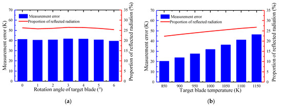
Figure 9.
Simulation analysis of the reflection error of turbine blade radiation temperature measurement: (a) angular factor distribution between the target blade and blade 2; (b) target point reflection ratio and temperature measurement error at different temperatures.
We then set the relative position coordinates of point to (0.5, 0.66), the target blade temperature range to 950–1250 K, at φ = 0 degrees, the guide vane temperature to 100 K lower than the target blade temperature, and the upper rotor blade temperature to the target blade temperature. The emissivity of the target blade is 0.58, and the wavelength of radiation temperature measurement is 1550 nm. The ratio of the reflected energy on the surface of the target blade to the total energy received by the radiation pyrometer and the temperature measurement error caused by reflection are calculated. The relationship between them and the temperature of the target blade is shown in Figure 9b. The proportion of reflected radiation and the reflected temperature measurement error increase as the target blade temperature increases. For aircraft turbine engines with a higher operating temperature, the temperature measurement error caused by reflection will be larger. Therefore, when performing radiation temperature measurement on turbine blades, target blade reflection must be corrected to reduce the resulting temperature measurement error.
2.4. Correction Method of Reflected Energy Based on Total Radiation Exitance of Adjacent Surface
This paper proposes a method of collecting radiation signals of the adjacent surface to correct for the reflection error in the process of radiation temperature measurement. Equation (3) shows that when ambient radiation is considered, the total radiant exitance of the target surface can be expressed as
In the narrow working wavelength range of the radiation pyrometer, the emissivity and radiation emission are considered, to a high approximation, not to change with the wavelength. Therefore, the actual signal output by the radiation pyrometer can be expressed as
where is the area of the object surface of the radiation pyrometer; is the solid angle of the entrance pupil of the optical system of the radiation pyrometer to a point on the object surface; is the product of the optical system’s transmittance, detector response coefficient, and other functions related to the wavelength; and is the operating bandwidth of the radiation pyrometer. Then, from the perspective of ambient radiation, according to Equations (16) and (17), the actual output signal of the radiation pyrometer can be expressed as
For the surface of the adjacent blades, is the total radiant exitance on the i-th panel of the adjacent blade surface, which includes heat radiation and reflection. As the target surface interrogated by the probe is very small (r = 1 mm), the temperatures of several surface elements contained on the probe target surface are considered equal. The total number of panels of the adjacent blades becomes , and the actual output signal of the detector can be expressed as follows:
is the actual voltage signal output of the detector, is the voltage signal of thermal radiation on the target surface, and is the voltage signal obtained using the same pyrometer to measure the -th panel of the adjacent blades’ surface; the last item includes the signal caused by the thermal radiation of adjacent blades themselves and reflection of other radiation sources on the blades’ surface. is the sum of the angle factors of several panels contained in the object plane of the radiation pyrometer. The radius of the object plane of a radiation pyrometer is generally on the order of millimeters, so it can be considered that the angular factors of the adjacent blade radiation at each point in the object plane are equal. The second term at the right end of Equation (19) is the signal response to the reflected energy, which can be calculated by the angle factor and the actual measured radiation signal without referring to the actual temperature and emissivity of the adjacent blade surface. The temperature measurement error can thus be reduced accordingly. As a versatile correction method, it benefits the temperature measurement performance of both single-wavelength and multi-wavelength frames.
3. Three-Wavelength Radiation Temperature Measurement Based on Reflection Correction
It is difficult to measure the emissivity of running turbine blades. For targets with unknown emissivity, the colorimetric temperature measurement algorithm is practical to measure the radiation temperature. However, suffering from both the ambient radiation and the emissivity difference with the wavelength, the relative temperature measurement error using the colorimetric algorithm could be higher than 15% [21]. Based on the above analysis of reflection error correction, the proposed algorithm has proven feasible in the radiation temperature measurement of a surface with unknown surface emissivity.
To eliminate the influence of blade surface emissivity, it is necessary to select multiple wavelengths for radiation measurement. When performing radiation temperature measurement of turbine blades, according to Equation (2), the response of the detector at a certain wavelength can be expressed as
where is the detector’s voltage signal output, is the surface emissivity, is the voltage signal of a blackbody measured by a radiation pyrometer with the same temperature as the target surface, is the voltage signal of the ambient radiation (obtained by combining the simulation results and measurement results of the reflection model), and is the detector noise. By deriving Equation (20), we obtain
Substituting wavelength 1 and wavelength 2 into Equation (21), we can obtain
We can divide Equation (22) and Equation (23) to obtain
Ignoring the difference in emissivity between the two wavelengths, we define the error function :
Then, the solution when is the true temperature of the target point. Combined with the mathematical properties of the Planck function, function satisfies the following conditions:
(1) The values of and the limit exist and are finite real numbers;
(2) In the domain , the function has a discontinuity point only at , and this point is the infinite discontinuity point of the function . The left limit and the right limit of the function at this point have opposite signs.
In the defined intervals and , the function is continuous. According to the zero-point theorem, if the function satisfies the following two conditions at the same time:
Function will have two zeros in the domain. Therefore, using only two wavelengths will result in two temperature solutions for temperature inversion.
When the target blade temperature is 1150 K, the guide vane temperature is 100 K lower, the upper rotor blade temperature is the same as the target blade temperature, the target blade emissivity is 0.58, detector noise is ignored, and two adjacent wavelengths of 1600 nm and 1500 nm are selected. We obtain a relationship between the error function and the temperature T at the measured point of the target blade, which is represented by the green curve in Figure 10. The function has two zero points: one at the real temperature = 1150 K, and the other at = 930.6 K. Both temperatures are within the working range of the turbine blade and are easily confused with its actual surface temperature.
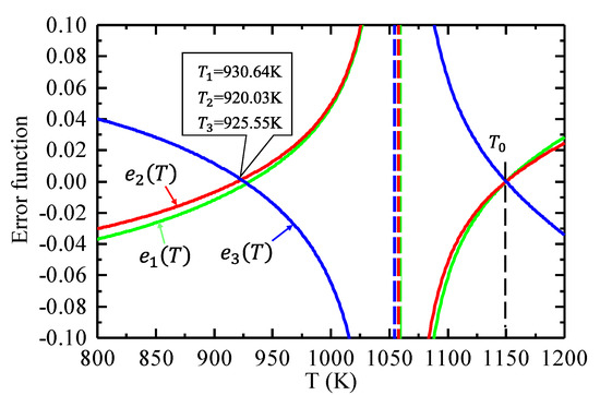
Figure 10.
Variation in the error function e(T) with temperature T (green: 1600 nm and 1500 nm; red: 1700 nm and 1600 nm; blue: 1500 nm and 1700 nm).
Then, three wavelengths, 1, 2, and 3, are selected. According to the error function , we can obtain two more error functions , and :
We define the error function of three-wavelength radiation thermometry algorithm:
We choose the center wavelengths of the three narrow bands beyond the strong absorption band of the engine gas as 1500 nm, 1600 nm, and 1700 nm and further analyze the relationship between the error functions (wavelengths 1600 nm and 1500 nm), (wavelengths 1700 nm and 1600 nm), and (wavelengths 1500 nm and 1700 nm) and the temperature T at the measured point of the target blade at a specific temperature.
The green curve in Figure 10 shows the relationship between and temperature T; the red curve shows the relationship between and temperature T; and the blue curve shows the relationship between and temperature T. The three curves have the same zero point at T = 1150 K, and the other zero points appear at T1 = 930.6 K, T2 = 920.03 K, and T3 = 925.55 K. The positions of these three zero points are not the same. Therefore, when Equation (30) is used as the three-wavelength error function, only the minimum function value 0 is obtained when T = 950 K, and the function values at other positions are all greater than 0, which ensures the uniqueness of the solution.
The temperature of the target surface can be reversed by the three-wavelength radiation temperature measurement algorithm, which only requires the radiation signal (, , and ) of the target surface and the ambient radiation signals (, , and are obtained from the simulation results of the reflection model combined with the measurement).
4. Experiment and Result Analysis
In order to verify the results of the three-wavelength radiation temperature measurement method based on reflection correction, an experiment was designed in a laboratory environment: a three-wavelength optical radiation pyrometer was used to measure the temperature of turbine blades in a heating furnace, and the three-wavelength radiation temperature measurement method based on reflection correction proposed in this paper and colorimetric temperature measurement methods were used to demodulate the blade temperature. The inversion results and the temperature errors of these methods are compared with those of thermocouples.
The experimental device designed and built by our group is shown in Figure 11. Three vanes and a target blade were placed in a heating furnace with a uniform temperature distribution according to their actual position in the engine. The probe was installed on the guide rail, and radiation from different positions of the target blade and the adjacent blades was collected through the shift and rotation of the probe. The radiation from the target blade was reflected to the lens group by the mirror in front of the probe, then converged into the optical fiber by the lens group, and finally entered the three-wavelength optical system through an optical fiber. In the optical system, radiation collimated by a collimator lens was divided into three beams by two dichroic mirrors. The radiation at each wavelength is focused on the detector of the corresponding channel after passing through its own filter. The temperature is demodulated based on the voltage output by the detector. The center wavelengths of the three narrow bands of radiation are 1500 nm, 1600 nm, and 1700 nm, and their bandwidths are all 50 nm.
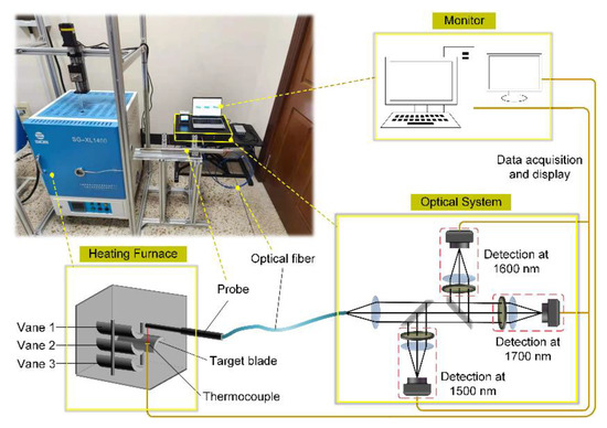
Figure 11.
Radiation temperature measurement experiment of turbine blade.
During the experiment, the temperature of the heating furnace was increased to 650 °C, 700 °C, 750 °C, 800 °C, 850 °C, 900 °C, and 950 °C. After the temperature in the furnace was stabilized, the probe was inserted for measurement. Radiation from the target blade, three guide vanes, and the upper surface of the heating furnace was collected by the probe. The center of the trailing edge of the suction surface of the target blade (point in Figure 6) was selected for temperature measurement. We collected the radiation from three points on the leading edge of the guide vane’s pressure surface (the quarter point of the guide vane) and from the 2 × 2 points on the upper surface of the heating furnace and took the average voltage signal of all points of each component to calculate the ambient radiation. In order to prevent overheating of the probe tip, which would allow thermal radiation from the reflector to interfere with measurement, the probe was withdrawn from the heating furnace after each measurement to be cooled with cold air. Although the distance from the probe to each blade is different, the temperature calibration results of a blackbody at different distances from the probe to the blackbody show that, as long as the temperature fluctuation of the surface to be measured is small and the object field of view of the radiation pyrometer is always full, changes in the temperature measurement distance hardly affect the output signal. Then, the measured radiation signals of the pressure surface of the guide vane and the upper surface of the heating furnace were substituted into Equation (20) to correct the reflected radiation of the target point. The radiation angle factors of the three guide vanes to the target point calculated using the three-dimensional dynamic reflection model of turbine blades proposed in this paper are shown in Table 1. The temperature of the measured point on the target blade, measured by a thermocouple, was used as the true temperature of the point. The voltage signals at seven temperature points on the target blade measured by the pyrometer in three channels (channel 1: 1500 nm; channel 2: 1600 nm; channel 3: 1700 nm) are shown in Figure 12a–c.

Table 1.
The angular factor between each part in the furnace and the target point on target blade.
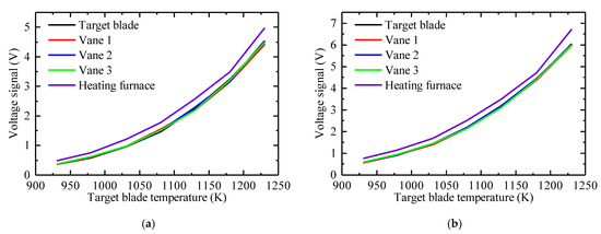
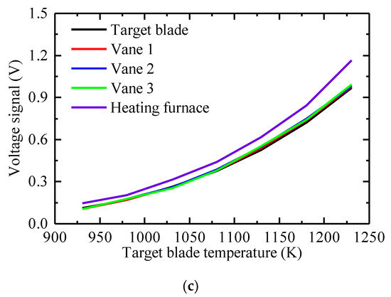
Figure 12.
Measurement results at different temperatures of: (a) channel 1: 1500 nm; (b) channel 2: 1600 nm; (c) channel 3: 1700 nm.
The measurement results show that the radiation signals collected at the three guide vanes (the temperature distribution of a guide vane is uniform, so the radiation average of three points on a vane is used to represent the radiation of the entire vane) are almost equal to the radiation signals collected at the target blade for different temperatures due to the uniform heating of the heater. The inner wall of the furnace is the main source of heat, so its radiation is higher than that of the blades in the furnace. With reference to the measurement and calculation results in Table 2, a three-wavelength radiation temperature measurement method, based on reflection error correction, and three colorimetric temperature measurement methods are used to demodulate the temperature. The four radiation temperature measurement methods are listed in Table 3, and the inversion results and relative errors are shown in Figure 13 and Figure 14.
Table 2.
Target blade radiation signal and the ambient radiation signal calculated using the three-dimensional dynamic reflection model.
Table 3.
Radiation temperature measurement methods used in the experiment.
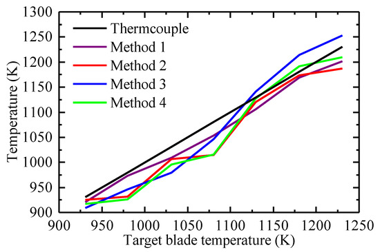
Figure 13.
Temperature measurement results of turbine blades.
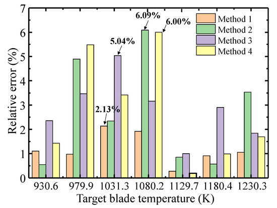
Figure 14.
Comparison between the inversion errors of the three-wavelength temperature measurement method and the colorimetric temperature measurement methods.
The three-wavelength radiation temperature measurement method based on reflection error correction proposed in this paper and the three colorimetric temperature measurement methods are listed in Table 3. The measured temperature results and relative temperature measurement errors of these radiation temperature measurement methods are compared, as shown in Figure 13 and Figure 14. The temperature measurement error of method 2 is the smallest at 930.6 K, and the error is only 0.55%, but the temperature error is 6.09% at 1080.2 K of the target blade temperature. In method 3, when the target blade temperature is 1129.7 K, the temperature measurement error is the smallest, only 0.996%, but when the target blade temperature is 1031.3 K, it reaches 5.04%. The temperature measurement error of method 4 is the smallest when the target blade temperature is 1129.7 K, only 0.19%, but it is 6.00% when the target blade temperature is 1080.2 K. The demodulated temperature results of the three colorimetric temperature measurement methods have considerable uncertainty. Analysis shows that the temperature measurement error is mainly affected by differences in emissivity of the blade at the three wavelengths, the reflection of ambient radiation, and measurement noise. The maximum temperature error of the proposed three-wavelength radiation temperature measurement method is 2.13% when the target blade temperature is 1031.1 K. The average relative errors of the four methods are 1.20%, 2.69%, 2.82%, and 2.74%, respectively. The demodulated temperature of the proposed method is close to the real temperature and is less affected by differences in emissivity and by measurement noise. The proposed method realizes the reflection error correction of the blade surface with unknown emissivity in a radiation environment and improves the accuracy of temperature measurement.
5. Conclusions
This paper proposed a three-wavelength radiation temperature measurement method for turbine blades based on ambient radiation correction. The method was used to measure the temperature of the surface of turbine blades with unknown emissivity subjected to ambient radiation. The first-stage rotor blade of the aero-turbine engine was selected as the target blade, and the adjacent guide vanes and the upper blades were selected as the adjacent blades. A three-dimensional dynamic reflection model of the turbine blades was established, and the target blades were analyzed under different rotation positions and different temperatures. Moreover, a three-wavelength radiation temperature measurement algorithm based on reflection error correction was proposed. Through theoretical deduction and analysis, the uniqueness of the algorithm for solving the temperature was proved. Ultimately, an experiment was designed to verify the method. The experimental results show that, compared with colorimetric temperature measurement methods, the maximum measurement error of the selected blade measurement points decreases from 6.09% to 2.13%, and the average measurement error decreases from a maximum of 2.82% to 1.20%. This indicates that the proposed method can eliminate the influence of reflected radiation and accurately obtain the temperature of a blade surface with unknown emissivity. The method would lead to a performance improvement in the radiation temperature measurement of aero-turbine engines. It should be noted that our analysis does not take into account the deformation of the turbine blade in the process of rotation. In future work, we will analyze the influence of deformation on the rotating blade temperature measurement. Additionally, we will calibrate the temperature error through modeling the deformed surface of turbine blades.
Author Contributions
Conceptualization, K.Z. and J.L. (Jinguang Lü); methodology, K.Z. and Y.Q.; software, K.Z. and Y.Z.; validation, J.L. (Jingqiu Liang) and Q.S.; formal analysis, K.Z. and W.W.; investigation, K.Z. and J.T.; writing—original draft preparation, K.Z.; writing—review and editing, J.L. (Jingqiu Liang), Y.Z., and Y.C.; funding acquisition, C.W. All authors have read and agreed to the published version of the manuscript.
Funding
This research was funded by the National Natural Science Foundation of China (Grant numbers 61727818, 61627819, 61805239), the National Key Research and Development Program of China under Grant 2019YFB2006000, the Jilin Scientific and Technological Development Program (Grant numbers 20190303063SF, 20150520101JH, 20180201024GX), and the Youth Innovation Promotion Association of the Chinese Academy of Sciences (Grant numbers 2018254).
Institutional Review Board Statement
Not applicable.
Informed Consent Statement
Not applicable.
Data Availability Statement
The study did not report any data.
Conflicts of Interest
The authors declare no conflict of interest.
References
- Kerr, C.; Ivey, P. Optical Pyrometry for Gas Turbine Aeroengines. Sens. Rev. 2004, 24, 378–386. [Google Scholar] [CrossRef]
- Kerr, C.; Ivey, P. An Overview of the Measurement Errors Associated with Gas Turbine Aeroengine Pyrometer Systems. Meas. Sci. Technol. 2002, 13, 873–881. [Google Scholar] [CrossRef]
- Mori, M.; Novak, L.; Sekavčnik, M. Measurements on Rotating Blades Using Ir Thermography. Exp. Therm. Fluid Sci. 2007, 32, 387–396. [Google Scholar] [CrossRef]
- Araújo, A.; Silvano, S.; Martins, N. Monte Carlo Uncertainty Simulation of Surface Emissivity at Ambient Temperature Obtained by Dual Spectral Infrared Radiometry. Infrared Phys. Technol. 2014, 67, 131–137. [Google Scholar] [CrossRef]
- Frank, S.L.F.; Holt, T.O.; Eisenlohr, H.; Raake, D. Application of a High Resolution Turbine Pyrometer to Heavy Duty Gas Turbines. In Proceedings of the ASME Turbo Expo 2001: Power for Land, Sea, and Air, New Orleans, LA, USA, 4–7 June 2001. [Google Scholar]
- Amory, D.C.; Hovan, R.A. Improving Gas Turbine Efficiency Using Optical Pyrometry. Turbomachinery 2004, 45, 22–24. [Google Scholar]
- Estevadeordal, J.; Nirmalan, N.; Wang, G.; Summerville, L. Multi-Color Pyrometry Techniques for Characterization of Spall in Heavy Duty Gas Turbine Engines. In Proceedings of the 42nd Aiaa Thermophysics Conference, Honolulu, HI, USA, 27–30 June 2012. [Google Scholar]
- Suarez-gonzalez, E.; Oqlukian, R.L. Triple Spectral Area Pyrometer. U.S. Patent 5125739A, 30 June 1992. [Google Scholar]
- Shu, Q.; Dai, S.; Nie, H.; Yi, W. Dynamic Temperature Compensation Model Based on Nonuniform Temperature Field Change. Infrared Phys. Technol. 2019, 101, 25–31. [Google Scholar] [CrossRef]
- Fu, T.; Liu, J.; Duan, M.; Zong, A. Temperature Measurements Using Multicolor Pyrometry in Thermal Radiation Heating Environments. Rev. Sci. Instrum. 2014, 85, 044901. [Google Scholar] [CrossRef] [PubMed]
- Lü, Y.; He, X.; Wei, Z.-H.; Sun, Z.-Y.; Chang, S.-T. Ambient Temperature-Independent Dual-Band Mid-Infrared Radiation Thermometry. Appl. Opt. 2016, 55, 2169–2174. [Google Scholar] [CrossRef] [PubMed]
- Hernandez, D.; Olalde, G.; Gineste, J.M.; Gueymard, C. Analysis and Experimental Results of Solar-Blind Temperature Measurements in Solar Furnaces. J. Sol. Energy Eng. 2004, 126, 645–653. [Google Scholar] [CrossRef]
- Lucia, M.; Lanfranchi, C. An Infrared Pyrometry System for Monitoring Gas Turbine Blades: Development of a Computer Model and Experimental Results. J. Eng. Gas Turbines Power 1992, 116, 172–177. [Google Scholar] [CrossRef]
- Gao, S.; Wang, L.; Feng, C.; Xiao, Y.; Daniel, K. Monitoring Temperature for Gas Turbine Blade: Correction of Reflection Model. Opt. Eng. 2015, 54, 065102. [Google Scholar] [CrossRef]
- Sun, B.; Sun, X.; Luan, M.; Dai, J.; Cui, S. Development of a Pyrometer That Measures the True Temperature Field of the Two-Dimensional Array. Appl. Sci. 2020, 10, 2888. [Google Scholar] [CrossRef]
- Khatami, R.; Levendis, Y.A. On the Deduction of Single Coal Particle Combustion Temperature from Three-Color Optical Pyrometry. Combust. Flame 2011, 158, 1822–1836. [Google Scholar] [CrossRef]
- Madura, H.; Kastek, M.; Piątkowski, T. Automatic Compensation of Emissivity in Three-Wavelength Pyrometers. Infrared Phys. Technol. 2007, 51, 1–8. [Google Scholar] [CrossRef]
- Fu, T.; Tan, P.; Pang, C.; Zhao, H.; Shen, Y. Fast Fiber-Optic Multi-Wavelength Pyrometer. Rev. Sci. Instrum. 2011, 82, 064902. [Google Scholar] [CrossRef] [PubMed]
- Sade, S.; Katzir, A. Spectral Emissivity and Temperature Measurements of Selective Bodies Using Multiband Fiber-Optic Radiometry. J. Appl. Phys. 2004, 96, 3507–3513. [Google Scholar] [CrossRef]
- Sparrow, E.; Cess, R. Radiation Heat Transfer. In Series in Thermal and Fluids Engineering; McGraw-Hill: New York, NY, USA, 1978. [Google Scholar]
- Ketui, D.; Chi, F.; Shan, G. Single Wavelength and Ratio Pyrometry Reflection Errors in Temperature Measurement of Gas Turbine Blade. Measurement 2016, 86, 133–140. [Google Scholar] [CrossRef]


Publisher’s Note: MDPI stays neutral with regard to jurisdictional claims in published maps and institutional affiliations. |
© 2021 by the authors. Licensee MDPI, Basel, Switzerland. This article is an open access article distributed under the terms and conditions of the Creative Commons Attribution (CC BY) license (https://creativecommons.org/licenses/by/4.0/).