Abstract
Recently, interest in using precast concrete (PC) modules has increased due to their better seismic performance than steel modules. However, they must be joined by additional elements to ensure structural integration between the modules. The essential aim of the precast concrete module is to ensure structural performance with appropriate connection methods. However, the technical problem of connecting PC modules still needs to be improved. This study proposed a PC modular beam system for improved structural and splicing performance, and simple construction. This modular system consisted of modules with steel plates inserted to improve integrity of modules, ease of construction, and low cost. The structural performance of the proposed PC modular beam system was evaluated by flexural test on one reinforced concrete (RC) beam specimen consisting of a monolithic beam, and two PC specimens with the proposed modular system. The results demonstrated that the proposed PC modular beam system achieved approximately 80% of the structural performance compared to the monolithic specimen, with approximately 1.3-fold greater ductility.
1. Introduction
Modular structures are designed to meet various building needs and are assembled on-site after factory production; therefore, their use is increasing due to their ease of construction and economic and environmental advantages [1,2]. Most modular buildings are constructed using precast concrete (PC) or steel. Steel modules are generally half the weight of their concrete contemporaries, making them an attractive option because they lead to cost savings [3]. However, PC modules are heavier than steel, making it more difficult to lift their weight as the building height increases. PC modules have the added disadvantage of needing to be bonded by special connecting hardware. Recently, however, interest in using PC modules has increased due to their better seismic performance than steel modules. Precast concrete has been used widely in a number of countries with high seismicity such as New Zealand, Japan, and Chile [4]. In addition, concrete with higher compressive strength such as reactive powder concrete can be adopted in precast concrete modules to ensure structural performance [5]. The problem of PC module weight has been addressed with the development of customized construction equipment, but the structural integration problem between PC modules to ensure structural performance must still be solved. Especially, the seismic behavior of precast concrete structures is highly dependent on the characteristics of connections between the precast structural members [4].
In general, PC modules are installed with steel connectors such as shoes or splice sleeves. Several studies have been carried out over the years to evaluate the capacity of different types of connections for precast concrete members [6,7,8]. Psycharis [9] carried out cyclic tests on a manufactured wall shoe, steel plate, and a test specimen connected by steel bars to determine which connection method resisted an earthquake most effectively when combined with a panel wall made of PC modules. In that experiment, the ductility and strength were excellent when the wall panels were connected with the wall shoe, but the steel bars were disadvantageous when the lateral displacement was large. Wu [10] analyzed the bending behavior of PC wall modules connected by shoes, and the connections were then bonded with waterproof tape or structural adhesive. The structural performance of all the test specimens was excellent, regardless of the arrangement of the wall shoe, but when they were bonded with waterproof tape, the structural performance was degraded due to a low splicing performance between the modules. Kuang and Zheng [11] assessed a method wherein components were connected by a grouted splice sleeve in a PC member, but found that it was difficult to evaluate the nonlinear behavior of the components when connected in that way. The studies have focused on the splicing methods between vertical and horizontal members to ensure the seismic performance of modular buildings. However, if the connection between the horizontal members is not ensured, usability problems will arise and there will be difficulties in splicing performance between the vertical and horizontal members. The PC modular horizontal members have mainly been used in bridge construction due to their superior quality control and the advantages of low life-cycle cost, ease of construction, and time saving [12]. Such PC members in bridges typically use shear keys on connections to increase the shear stiffness and shear capacity between the modules. The shear keys act to inhibit the generation of shear slip in the connections, and the shear performance of the connections is greatly influenced by the shape of the shear keys. In PC construction, there are male-to-female [13,14] or female-to-female keys [15,16], as shown in Figure 1, and steel bars between the modules are connected using spliced sleeves or lapped splices. Finally, epoxy is used to fill in the non-shrinkage mortar between the shear keys to splice the two modules together [12,17].
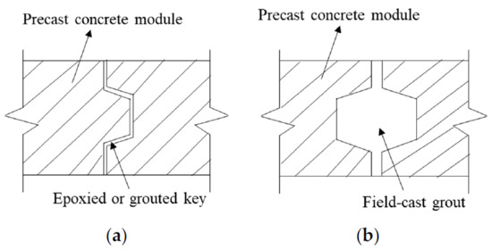
Figure 1.
Types of shear keys: (a) male-to-female key; (b) female-to-female key.
Recently, prestress has been introduced to improve the splicing performance between PC modules. A bridge is a long span structure, and its intended use is different from that of buildings; therefore, it is not suitable to use the same shape of connections in the horizontal PC modular members as in buildings. Therefore, this study proposes a PC modular beam system with improved integrity and a simplified construction process. To evaluate the structural performance, flexure tests were conducted on one monolithic reinforced concrete beam specimen and two proposed PC modular beam specimens.
2. Proposed Modular Concrete Beam System
This study proposed a splicing method of PC modular horizontal members suitable for buildings, such as in Figure 2. The proposed PC modular beam system consists of modules with steel plates inserted, which were U-shaped and I-shaped, as shown in Figure 3. I-shaped steel plates slide from the top to the bottom of the U-shaped steel plate and are then connected once more by a bolt connection; therefore, the splicing performance could be improved. Additionally, because it was inserted from the top to the bottom by sliding, it is possible to work immediately with the PC module being lifted, so construction can be easier. This proposed PC modular beam has a simpler shape than the PC module with a shear key, and the proposed modules were joined by grouting them with non-shrink mortar, not epoxy. Non-shrink mortar is cheaper than epoxy adhesive, and has good fluidity; therefore, it can fill the spliced part well and also possibly reduce construction costs.
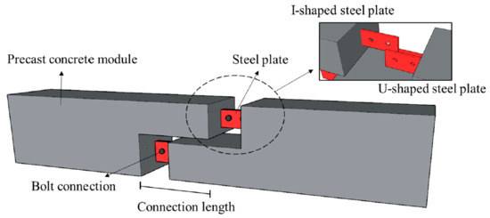
Figure 2.
Scheme of proposed precast concrete modular beam system.
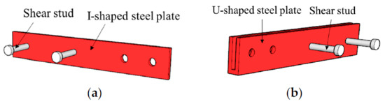
Figure 3.
Steel plates: (a) I-shaped steel plate; (b) U-shaped steel plate.
The detailed process of the proposed construction method is shown in Figure 4. The PC module was connected by inserting an I-shaped steel plate into a U-shaped steel plate. Then, the bolts between the steel plates were connected, and finally a non-shrink mortar was injected between the two modules.
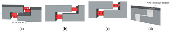
Figure 4.
Construction process of proposed precast concrete modular beam system: (a) inserting an I-shaped steel plate into a U-shaped steel plate; (b) splice connection between steel plates; (c) bolt connection between steel plates; (d) injection of non-shrink mortar.
3. Experimental Program
3.1. Specimen Details
To evaluate the structural performance of the proposed system and analyze its splicing performance, one monolithic RC test beam (hereafter, control reinforced concrete CRC) and two PC modular beam specimens were fabricated. The connection length of the PC modular which shown in Figure 2 has a significant impact on the structural performance of the entire system; therefore, it was set as a variable. The notation of specimens is presented in Figure 5. The material properties were measured by Korean standards. Korean standards specified that the material properties could be determined as the average test results of three or more specimens. The compressive strength test of concrete was carried out according to the Korean standard KS F 2405 [18]. Three concrete cylinders (150 × 300 mm) were manufactured for compressive strength test. The compressive strength of concrete was measured after 28 days of curing and the average of three specimens was 23.12 MPa. The compressive strength of non-shrink mortar was measured through the Korean standard KS L 5105 [19]. Three cube specimens (50 × 50 × 50 mm) were tested, and the average compressive strength of non-shrink mortar was 58 MPa. The yield strengths of deformed reinforcement and steel plates were measured according to the Korean standard KS B 0802 [20], and three specimens were tested. The deformed reinforcement was 19 mm in diameter, and stirrups with a diameter of 10 mm were arranged at 150 mm intervals to prevent shear failure of the beams. The average yield strength of reinforcement was 406.49 MPa. The steel plate inserted into the PC modular was manufactured using SS275 steel, and the average yield strength of 269.79 MPa. Figure 6 presents the stress–strain curve of a representative specimen. The dimensions of the test specimens are shown in Figure 7: 300 mm wide and 350 mm high, with a total length of 4500 mm. In Figure 7, only the left module is shown for the PCM test specimen; the right module is symmetrical. Details of the test specimens are shown in Table 1.
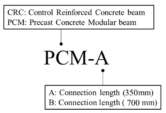
Figure 5.
Notation of specimens.
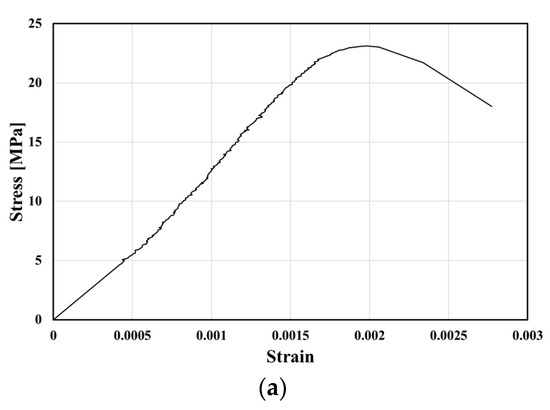
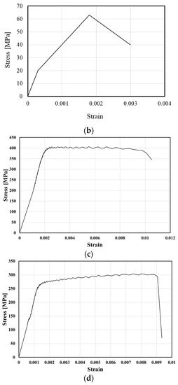
Figure 6.
Stress–strain curve: (a) concrete; (b) non-shrink mortar; (c) deformed reinforcement; (d) steel plate.
Figure 7.
Details of specimens (mm): (a) A-A section; (b) B-B section; (c) side view of CRC; (d) side view of PCM-A; (e) side view of PCM-B.

Table 1.
Details of specimens.
Figure 8 shows the process of constructing the proposed PC modular beam. A factory-produced PC modular beam was transported to the site and the steel plate was assembled. Finally, shear studs were used to assemble the steel plates. The PC modules were spliced by injecting non-shrink mortar. The compressive strength of mortar was observed through a uni-axial compression test, and after reaching the design compressive strength of mortar, 60 MPa, the form was removed. Finally, the two modules could be fully bonded.
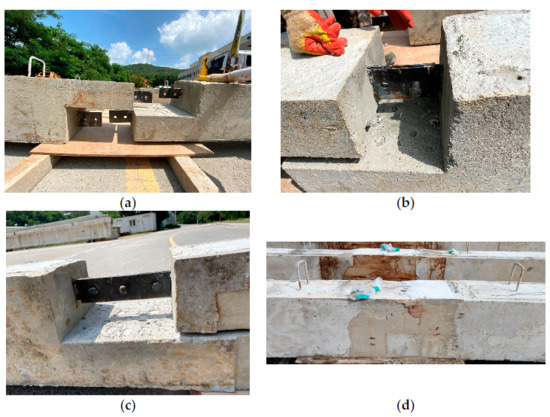
Figure 8.
Construction process of proposed PC modular beam system: (a) PC modules; (b); assembling the steel plates; (c) connection with shear studs; (d) non-shrink mortar injection.
3.2. Test Setup
The flexure tests were conducted to investigate the structural performance and splicing performance of the proposed PC modular beam system. The supports were installed 200 mm from both ends of the specimen for simply supported condition, and loading points were 1750 mm away from the center of each supports. Two-point loading was applied at a rate of 2 mm/min using a hydraulic universal testing machine (UTM) with a capacity of 500 tons. To measure the displacement of the test specimen, an LVDT was installed at the center and 300 mm from the center of the test specimen. The specimen setup is shown in Figure 9. To observe the strain of each specimen, a strain gauge was attached to the concrete, the reinforcement steel, and the steel plate inserted into the PC module. The PC modules were symmetrical; thus, the gauge was attached to only one module. The gauge attachment position is shown in Figure 10. The instruments installed on the specimens are summarized in Table 2, and they are used widely in technical studies when measuring test results such as strain and displacement [21,22,23].
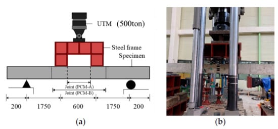
Figure 9.
Test setup for flexural test: (a) schematic test setup (mm); (b) view of test setup.
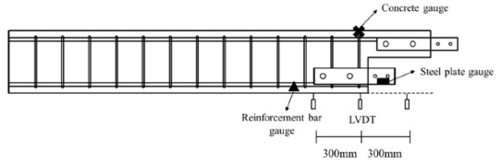
Figure 10.
Position and naming of gauges.
Table 2.
Instruments installed on specimens.
4. Experimental Results and Analysis
4.1. Cracks and Failure Modes of the Specimens
The crack patterns and failure of specimens are shown in Figure 11. Initial cracks were observed at the midspan on all of the specimens, but as the load increased, the crack patterns differed in each specimen. As in typical reinforcement concrete beams, the flexural cracks in CRC occurred in the midspan, and were propagated into the compression zone. In the PCM-A and PCM-B which connected to the two PC modules, cracks occurred at the bottom of the connection while the flexural cracks were increasing, and they subsequently progressed along the shape of connection to the compression zone. In the beams with joints, cracks progressed along joint configuration [24,25,26]. Therefore, this result indicated the general behavior of precast concrete beams with joints. The structural performance of a beam with joints should be similar to a monolithic beam, and it can be confirmed by crack patterns. The PC modular beam system proposed here had initial crack patterns similar to those in typical RC beams, which indicates that the proposed system could be applied at actual construction sites. The PC modules were connected in the midspan where flexural cracks occurred in the beams. Thus, flexural cracks occurred in the connections between the modules, and the length of the connection affected the integrity of the structure. Comparing the cracks in the two different connection lengths, cracks began in the PCM-A (350 mm connection length) when the displacement was 30 mm and the load reached 84% of the maximum. In the PCM-B (700 mm connection length), the cracks began when the displacement was 20 mm and 90% of the maximum load was reached. This confirmed that the PCM-B with the longer connection was more brittle than the PCM-A. The failure of specimens is shown in Figure 12. As shown in Figure 12a, the CRC specimen had a large number of cracks in the midspan compared to the other test specimens because it was monolithic. Unlike the CRC, the PC module specimens had few flexural cracks in the center, as shown in Figure 12b,c, and also propagated along with the shape of the connection. However, it was confirmed that the PC module-to-PC module connections were not detached or partially destroyed.

Figure 11.
Crack patterns of specimens: (a) CRC; (b) PCM-A; (c) PCM-B.

Figure 12.
Failure of specimens in the midspan: (a) CRC; (b) PCM-A; (c) PCM-B.
4.2. Load–Displacement Relationships and Strains
The results of the flexure tests on each test specimen are summarized in Table 3, and the load–displacement curves are shown in Figure 13. The maximum load of the CRC was 175.65 kN. The maximum loads on the PCM-A and PCM-B, which were PC modular members, were 141.86 kN and 137.75 kN, respectively, which were 88% and 78% that of the CRC specimen. These results show good agreement with previous studies on PC modular members, that PC modular members usually perform at 70% to 85% of general RC members’ capacity [12,27]. Accordingly, we confirmed that the proposed PC modular beam systems performed as well as monolithic members.
Table 3.
Test results.
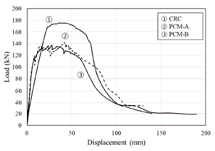
Figure 13.
Load–displacement curves.
This study also verified that the proposed system meets the requirements of current design codes, such as the ACI 318-19 standard [28]. The nominal moment strength equations of RC beams presented in the ACI standard are as follows:
where is the non-prestressed longitudinal tension reinforcement, is the yield strength of the non-prestressed reinforcement, d is the distance from the extreme compression fiber to the centroid of the longitudinal tension reinforcement, and a is the depth of the equivalent rectangular stress block, as shown in Figure 14.
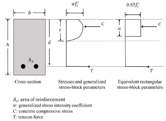
Figure 14.
Definition of rectangular stress distribution.
The nominal moment strengths of all the test specimens were calculated to be 120.8 kNm. Experiments showed that the moment strengths of the CRC, PCM-A, and PCM-B were 127%, 103%, and 101%, respectively, compared to the normal moment strength calculated through ACI code. This demonstrated that the proposed beam system could be designed using the design method of typical RC beams.
The strain on each specimen was analyzed with gauges attached to the concrete, rebars, and steel plates, as shown in Figure 15. The load–strain curves of PCM-A and PCM-B showed discontinuities because mortar injecting connection zone was crushed as load increased. According to a concrete gauge in the compression zone, the CRC reached the ultimate compressive strain of the concrete, 0.003. In the PCM and PCM-B, the strain gauge was damaged, and its subsequent behavior was not measured. However, the concrete in the compression zone was crushed, and it can be considered that concrete reached the ultimate compressive strain. Furthermore, in the PCM-A and PCM-B, the stiffness decreased at the beginning of the experiment because the load was applied on the mortar of the connection, but the subsequent behavior patterns and stiffness were similar to that of the monolithic reinforced concrete beam specimen.
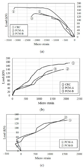
Figure 15.
Comparison of strain gauges: (a) concrete strain gauge; (b) rebar strain gauge; (c) steel plate strain gauge.
For the rebar gauges shown in Figure 15b, the PCM-A and PCM-B did not reach the yield strain of the rebar, 0.002, unlike the CRC. This was due to the strain of the steel plate inserted into the PC module in the tension zone. At the maximum load of the PCM-A and PCM-B, the rebar strains were 0.0018 and 0.0015, respectively, indicating integrity between the PC modules. The strain of the steel plate inserted into the PC module beam system was observed, and is shown in Figure 15c. The yield strain of the steel plate was 0.00138, and steel plates inserted into precast concrete specimens exceeded 0.00138 near the maximum load. This behavior was observed equally in the PCM-A and PCM-B specimens. The compressive force of the steel plate at the beginning of the experiment was negligible. The test results indicated that it is possible to ensure structural performance as well as splicing performance between the PC modules through the steel plate resistive tensile force. In PCM-A and PCM-B, similar to monolithic beams, the strain in the compression zone reached the ultimate compressive strain of concrete, and the strain in the tensile zone exceeded the yield strain of steel plate. According to this result, it was confirmed that the stress between each module was transferred well through the joint.
4.3. Evaluation of Displacement Ductility
Ductility is a critical factor in assessing structural performance in a component where bending behavior is dominant. In this study, the method presented in Sheikh and Khoury [29] was used to evaluate the ductility of the members. The ductility of the members was evaluated by the displacement ductility index, which is the value of the ratio of ultimate displacements () to the yield displacement (). As shown in Figure 16, yield displacement is the displacement value when the maximum load is reached, and ultimate displacement means the displacement value of 80% of the maximum load after reaching the maximum load. The displacement ductility index of specimens are summarized in Table 4. The PCM-A and PCM-B consisting of the PC modules had a 1.35-fold higher ductility index and were 1.22-fold higher than the CRC, which is monolithic. In addition, ductility of members can be quantified by integrals of the area under the stress–strain curve [30] as shown in Figure 17. The ductility indexes are summarized in Table 5 and Figure 18. In Figure 18, the ductility index of the CRC specimen was set to 1. The ductility indexes of PCM-A and PCM-B consisting of the PC modules were 1.25- and 1.16-fold higher, respectively, than the CRC, which is monolithic. This demonstrated that the PC modular beam system proposed in this study was capable of splicing between PC modules, and improved ductility due to the steel plates inserted into the modules. The PCM-A with a 350 mm connection length was 1.1-fold more ductile than the PCM-B with a connection length of 700 mm, showing that the effect of connection length on the ductile performance was insignificant.
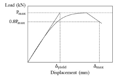
Figure 16.
Displacement ductility.
Table 4.
Comparison of displacement ductility.
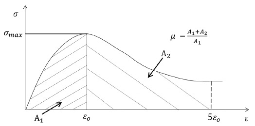
Figure 17.
Diagram for the description of displacement ductility.
Table 5.
Comparison of displacement ductility index.
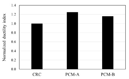
Figure 18.
Comparison of normalized ductility index.
5. Conclusions
In this study, a PC modular beam system was proposed in order to improve structural integrity and simplify the construction process. To evaluate the structural performance of the proposed system, a monolithic reinforcement concrete beam and two proposed PC modular beams with different connection lengths between the modules were fabricated and a flexural experiment was conducted. The conclusions of this study are as follows:
- (1)
- An initial crack occurred in the midspan of all the test specimens. In the proposed PC modular beam system, PCM-A and PCM-B, cracks progressed along the shape of connection to the compression zone as the load increased after the initial flexural crack occurred. The PCM-B with a 700 mm connection length (twice that of the PCM-A specimen) was more brittle. However, the splicing between the PC modules was ensured because the connections between the PC modules did not detach until the test was terminated;
- (2)
- The maximum loads of the PCM-A and PCM-B were 81% and 78%, respectively, of the maximum load of the monolithic specimen. The load resistance capacity of PC modular members is typically about 70–85% compared to standard RC beams; thus, the proposed system performed the same as general PC modular members. Furthermore, the normal moment strengths of the PCM-A and PCM-B specimens obtained experimentally were 103% and 101%, respectively, of that calculated by the ACI 318-19 design standard, meaning it was possible to verify the flexural strength of the proposed method using the current design code;
- (3)
- It was observed for all the specimens that the concrete strains in the compressive zone at the middle of the beam reached the ultimate compressive strain. The rebars in PCM-A and PCM-B did not reach the yield strain of the steel, 0.002, unlike the CRC, the monolithic beam. This is because steel plates inserted into the precast concrete specimens resisted flexural load instead of the discontinuous rebars. This means that the proposed connection showed sufficient structural performance as well as splicing performance;
- (4)
- The ductility indexes of the PCM-A and PCM-B were 1.3- and 1.2-fold higher, respectively, than that of the CRC. This was due to the improved ductility from the steel plates of the PC modules, and it confirmed that the high integrity was ensured between the PC modules. The connection length had only a small effect on the ductile performance. To provide design guidelines for the proposed PC modular beam, more analytical and experimental studies are needed.
Author Contributions
Conceptualization, K.-M.R. and Y.-H.L.; methodology, K.-M.R.; validation, M.-S.K. and C.-G.C.; formal analysis, K.-M.R.; investigation, M.-S.K. and C.-G.C.; writing—original draft preparation, K.-M.R.; writing—review and editing, Y.-H.L. All authors have read and agreed to the published version of the manuscript.
Funding
This research was supported by a National Research Foundation of Korea grant (NRF-2019R1A4A1028116), funded by the Ministry of Education, Korea.
Institutional Review Board Statement
Not applicable.
Informed Consent Statement
Not applicable.
Data Availability Statement
Data sharing not applicable.
Conflicts of Interest
The authors declare no conflict of interest.
References
- Innella, F.; Arashpour, M.; Bai, Y. Lean methodologies and techniques for modular construction: Chronological and critical review. J. Constr. Eng. Manag. 2019, 145. [Google Scholar] [CrossRef]
- Thai, H.T.; Ngo, T.; Uy, B. A review on modular construction for high-rise buildings. Structures 2020, 28, 1265–1290. [Google Scholar] [CrossRef]
- Dai, Z.; Pang, S.D.; Liew, J.R. Axial load resistance of grouted sleeve connection for modular construction. Thin Walled Struct. 2020, 154. [Google Scholar] [CrossRef]
- Kurama, Y.C.; Sritharan, S.; Fleischman, R.B.; Restrepo, J.I.; Henry, R.S.; Cleland, N.M.; Ghosh, S.K.; Bonelli, P. Seismic-resistant precast concrete structures: State of the art. J. Struct. Eng. 2018, 144. [Google Scholar] [CrossRef]
- Bujnak, J.; Michalek, P.; Bahleda, F.; Grzeszczyk, S.; Matuszek-Chmurowska, A.; Mordak, A. Mechanical Testing of Composite Steel and Reactive Powder Concrete Structural Element. Materials 2020, 13, 3954. [Google Scholar] [CrossRef] [PubMed]
- Rave-Arango, J.F.; Blandón, C.A.; Restrepo, J.I.; Carmona, F. Seismic performance of precast concrete column-to-column lap-splice connections. Eng. Struct. 2018, 172, 687–699. [Google Scholar] [CrossRef]
- Choi, H.K.; Choi, Y.C.; Choi, C.S. Development and testing of precast concrete beam-to-column connections. Eng. Struct. 2013, 56, 1820–1835. [Google Scholar] [CrossRef]
- Parastesh, H.; Hajirasouliha, I.; Ramezani, R. A new ductile moment-resisting connection for precast concrete frames in seismic regions: An experimental investigation. Eng. Struct. 2014, 70, 144–157. [Google Scholar] [CrossRef]
- Psycharis, I.N.; Kalyviotis, I.M.; Mouzakis, H.P. Experimental investigation of the response of precast concrete cladding panels with integrated connections under monotonic and cyclic loading. Eng. Struct. 2018, 159, 75–88. [Google Scholar] [CrossRef]
- Wu, X.; Xia, X.; Kang, T.H.; Han, J.; Kim, C.S. Flexural behavior of precast concrete wall-steel shoe composite assemblies with dry connection. Steel Compos. Struct. 2018, 29, 545–555. [Google Scholar]
- Kuang, Z.; Zheng, G. Computational and experimental mechanical modelling of a composite grouted splice sleeve connector system. Materials 2018, 11, 306. [Google Scholar] [CrossRef]
- Kim, M.S.; Lee, Y.H. Structural behavior of spliced post-tensioned girders with precast box segments. Int. J. Concr. Struct. Mater. 2019, 13, 21. [Google Scholar] [CrossRef]
- Issa, M.A.; Abdalla, H.A. Structural behavior of single key joints in precast concrete segmental bridges. J. Bridge Eng. 2007, 12, 315–324. [Google Scholar] [CrossRef]
- Zhang, X.; Hao, H.; Zheng, J.; Hernandez, F. The mechanical performance of concrete shear key for prefabricated structures. Adv. Struct. Eng. 2021, 24, 291–306. [Google Scholar] [CrossRef]
- Yamane, T.; Tadros, M.K.; Badie, S.S.; Baishya, M.C. Full-Depth Precast Prestressed Concrete Bridge Deck System. PCI J. 1995, 43, 50–66. [Google Scholar] [CrossRef]
- Menkulasi, F.; Roberts-Wollmann, C.L. Behavior of horizontal shear connections for full-depth precast concrete bridge decks on prestressed I-girders. PCI J. 2005, 50, 60–73. [Google Scholar] [CrossRef]
- Park, J.; Choi, J.; Jang, Y.; Park, S.K.; Hong, S. An experimental and analytical study on the deflection behavior of precast concrete beams with joints. Appl. Sci. 2017, 7, 1198. [Google Scholar] [CrossRef]
- KS F 2405. Method of Test for Compressive Strength of Concrete; Korea Standards Association: Seoul, Korea, 2017. [Google Scholar]
- KS L 5105. Testing Method for Compressive Strength of Hydraulic Cement Mortar; Korea Standards Association: Seoul, Korea, 2017. [Google Scholar]
- KS B 0802. Method of Tensile Test for Metallic Materials; Korea Standards Association: Seoul, Korea, 2013. [Google Scholar]
- Gunasekaran, K.; Annadurai, R.; Kumar, P.S. Study on reinforced lightweight coconut shell concrete beam behavior under shear. Mater. Des. 2013, 50, 293–301. [Google Scholar] [CrossRef]
- Zeng, J.; Guo, Y.; Li, L.; Chen, W. Behavior and three-dimensional finite element modeling of circular concrete columns partially wrapped with FRP strips. Polymers 2018, 10, 253. [Google Scholar] [CrossRef]
- Huda, M.N.; Jumat, M.Z.B.; Islam, A.S. Flexural performance of reinforced oil palm shell & palm oil clinker concrete (PSCC) beam. Constr. Build. Mater. 2016, 127, 18–25. [Google Scholar]
- Kankeri, P.; Prakash, S.S. Experimental evaluation of bonded overlay and NSM GFRP bar strengthening on flexural behavior of precast prestressed hollow core slabs. Eng. Struct. 2016, 120, 49–57. [Google Scholar] [CrossRef]
- Hussein, H.H.; Sargand, S.M.; Al Rikabi, F.T.; Steinberg, E.P. Laboratory evaluation of ultrahigh-performance concrete shear key for prestressed adjacent precast concrete box girder bridges. J. Bridge Eng. 2017, 22. [Google Scholar] [CrossRef]
- Hussein, H.H.; Sargand, S.M.; Steinberg, E.P. Shape optimization of UHPC shear keys for precast, prestressed, adjacent box-girder bridges. J. Bridge Eng. 2018, 23. [Google Scholar] [CrossRef]
- Breccolotti, M.; Gentile, S.; Tommasini, M.; Materazzi, A.L.; Bonfigli, M.F.; Pasqualini, B.; Colone, V.; Gianesini, M. Beam-column joints in continuous RC frames: Comparison between cast-in-situ and precast solutions. Eng. Struct. 2016, 127, 129–144. [Google Scholar] [CrossRef]
- ACI Committee 318. Building Code Requirements for Reinforced Concrete and Commentary (ACI 318-19); American Concrete Institute: Farmington Hills, MI, USA, 2019. [Google Scholar]
- Sheikh, S.A.; Khoury, S.S. A performance-based approach for the design of confining in tie columns. ACI Struct. J. 1997, 94, 421–431. [Google Scholar]
- Ahmmad, R.; Jumaat, M.Z.; Bahri, S.; Islam, A.S. Ductility performance of lightweight concrete element containing massive palm shell clinker. Constr. Build. Mater. 2014, 63, 234–241. [Google Scholar] [CrossRef]


Publisher’s Note: MDPI stays neutral with regard to jurisdictional claims in published maps and institutional affiliations. |
© 2021 by the authors. Licensee MDPI, Basel, Switzerland. This article is an open access article distributed under the terms and conditions of the Creative Commons Attribution (CC BY) license (https://creativecommons.org/licenses/by/4.0/).