1. Introduction
The use of latent heat thermal energy storage (LHTES) modules for temperature control has been proposed for a variety of systems. These include spacecraft, handheld electronics, electric vehicles, and robotic systems [
1,
2,
3,
4]. LHTES modules are useful for thermal management of systems that generate heat following an intermittent/variable profile. During periods in which heat generation rates are high, the PCM undergoes a phase transition, absorbing heat and slowing the system’s temperature rise. Heat stored in the LHTES is subsequently released to the environment during periods with low heat generation rates. In systems with cyclic heating, this process is similar to peak shaving.
Thermal management of handheld electronic devices such as smart phones and tablet computers presents a number of challenges. The temperature of the internal components must be kept within their operating range. Surface temperatures must be kept below the user’s comfort threshold. Space availability and noise constraints make traditional active thermal management systems difficult to implement. However, it may be possible to leverage the intermittent operation of these devices with a LHTES thermal management module [
5,
6].
Modern handheld electronic devices use thermal throttling to manage their temperature. If a component is approaching its temperature limit, the device reduces its operating speed in order to lower heat generation rates. The major goals of passive thermal management modules are to reduce the rate of temperature rise and avoid or delay performance drops due to thermal throttling. In addition, reducing the mean temperature of internal components can increase reliability and help prevent premature failures. The critical temperatures for internal components and the device surface can vary depending on a number of design choices. In this work, the handheld device will be considered to have overheated if an internal temperature is measured to exceed 80 °C or if the surface of the device exceeds 40 °C [
7,
8].
Much of the research on LHTES-based thermal management systems has been directed towards applications larger than would be suitable for handheld electronics. Many of these LHTESs can be characterized as hybrid heat sinks. In essence, a hybrid heat sink combines a finned heat sink with a LHTES by fully or partially filling the space between the fins with PCM. Systems of this type have been investigated in many different sizes and configurations, including plate fin [
9,
10,
11], pin fin [
12,
13,
14], and metal foam [
15].
However, modern handheld devices are typically less than 1 cm thick, and for a LHTES to be viable in these systems, it would have to be a fraction of that size (only a few mm thick). Only a few research groups around the world have published on work performed on thin LHTESs. Fundamental work on the use of thin LHTES modules for thermal management was carried out by Maranda et al. (2019) [
16]. Using a simplified setup, LHTES modules (100 mm × 100 mm × 2 mm) were experimentally tested. These modules were created by encapsulating PCM between two sheets of heat-sealed laminated film. Both
n-eicosane and dodecanoic acid were tested. In the experiments, the LHTES module was placed in a cavity between an insulated Teflon base and a nylon cover. A copper heating block embedded in the base simulated the small discrete heat sources that are present in handheld electronic devices. The heat source was on (constant 5 W) for a period of 60 or 120 min, depending on the study, after which the sources were turned off and the package was allowed to cool to ambient temperature. The measured transient temperature histories showed that the LHTES module slowed the temperature rise of both the heating block and the nylon cover. However, due to its extreme aspect ratio, the LHTES module was much more effective when paired with an aluminum heat spreader, pointing to the fact that heat spreading is poor in such a laminated PCM LHTES. The study of Li et al. (2016) also looked at the impact of spreading in a PCM module, combining it with flat heat pipes [
17]; the additional thermal spreading reduced the module’s temperature. While promising, these studies were done with a simple experimental apparatus that does not fully capture the complex internal heat transfer of a handheld electronic device.
Sponagle et. al. (2019) [
18] used a numerical model of a tablet computer to investigate the impact of the transition temperature of a PCM on the performance of the LHTES module. That study used a comparative analysis to show that a lower transition temperature is most beneficial for this application. Additionally, that study investigated how heat is transferred within the tablet. However, there were aspects of this model that could not replicate the physics of a real tablet computer. Predominate among these were simulation of contact resistance between the components within the tablet and accurately modeling the convection from the surface of the tablet.
That study showed that experimental investigations of LHTES modules within an experimental apparatus representative of actual handheld electronic devices are required. Such studies have been attempted with older, larger handheld electronic devices. Hodes et al. (2002) [
19] experimentally tested the use of a LHTES module in a telephone handset. Alawadhi and Amon (2003) [
15] investigated a LHTES module in a mock wearable computer. However, the LHTESs used in both studies were thicker than an entire modern mobile device.
Tomizawa et al. (2016) [
20] studied the integration of a LHTES unit into the temperature control system of a mock handheld computing device that was close to the size of a modern device (122 mm × 62 mm × 14 mm). This mock device consisted of a case made from 1 mm sheets of acrylic (rear) and a 1 mm polycarbonate sheet (front and side). An electric ceramic heater was mounted to simulate a printed circuit board (PCB). The LHTES unit consisted of a microencapsulated paraffin powder (
Tm = 32 °C) that was mixed (50% by weight) with polyethylene (PE). This mixture of microencapsulated PCM and PE was cast into sheets that were 25 mm × 25 mm × 4 mm and 50 mm × 50 mm × 1 mm. Melting experiments were completed with a steady power input of 2 W. They found that the sheets delayed the rise in the system’s temperature and reduced the system’s steady-state temperature. The use of a mock handheld device and LHTES module that could fit into a modern handheld device makes this study particularly relevant. However, the mock device was only a basic representation of a modern device and did not contain a battery or display. Additionally, when the microencapsulation and shape stabilization materials are accounted for, the total thermal energy storage of the LHTES used was small.
Ahmed et al. [
5,
6] presented the first published work employing a real mock-up tablet PC, an experimental rig built on a modified Dell Venue tablet computer. The main PCB of the tablet was removed and replaced with a PCB constructed of FR4 copper-clad board. A polyimide heater was used to simulate the heat generated by the processor. Several LHTES storage modules consisting of PCM sealed in pouches manufactured from heat-sealable aluminized film were tested. Both
n-eicosane (
Tm = 35.6 °C) and a commercial PCM called PT-37 (
Tm = 36.4 °C) were tested. Analysis of the tablet computer’s temperature history showed that the LHTES modules delayed the temperature increase in both the heater and the cover of the tablet computer. However, it was also shown that many of the modules did not melt completely during the experiment and that the lack of a heat spreader was detrimental to their performance. While promising, the lack of a heat spreader makes it difficult to truly judge the utility of the LHTES module from that study. Additionally, the manufacturing technique used to create the LHTES modules resulted in uneven thicknesses.
Based on the recent work showing issues of heat spreading, and the paucity of research work published using real representative mock-up tablet PCs, the objective of the present work was to experimentally determine the feasibility of using a PCM-based temperature control module, in conjunction with a heat spreader and thermal interface material, to improve the thermal management of a tablet computer.
The mock tablet was constructed utilizing a combination of components from a disassembled tablet computer and mock components constructed specifically for the experiment. This mock tablet combines the advantages of using realistic materials, while maintaining control of the experimental space. Additionally, a rigorous and well-controlled method was used to make LHTES modules of a specific thickness. Using this apparatus and techniques, a series of transient heating and cooling experiments was performed to determine the impact of the PCM module on the thermal response of the mock tablet. The results of a full investigation, including the use of a heat spreader and a thermal interface material (TIM), are presented. As justified in the literature review above, the present work represents the first study that combines thin PCM thermal storage for temperature management of a thin modern electronic device, using essentially a real tablet device for testing, and a thermal spreader and thermal interface materials as is typical of modern electronics. In approach and impact, this study is both novel and timely.
2. Materials and Methods
2.1. Mock Tablet
The core experimental setup was a mock tablet based partly on a Dell Venue 8 Pro tablet computer. Both the display assembly and battery from the original tablet were used in the mock tablet. A new cover was created using a 1/16” thick sheet of nylon and ABS frame components. This cover was easier to attach and remove than the original, so could easily be replaced, and allowed for more control of the experimental space. The PCB from the Dell tablet was replaced by a simulated PCB cut to the same shape from FR4 copper clad board.
The heat source used in these experiments was a 2.54 mm square polyimide film heater that was placed in the location of the system on a chip (SoC) from the Dell tablet (see
Table 1). This heater came from the manufacturer with adhesive on one surface, and it was adhered to a 2.54 mm (1”) square, 0.4 mm thick piece of aluminum and was then coupled to the PCB using thermal paste (Tgrease 880) and a piece of polyimide tape.
The experimental apparatus was 149.1 mm wide by 234.5 mm long. From the back cover to the front of the display, it was 11.6 mm thick.
Figure 1 shows a solid model of the experimental apparatus with the components labeled.
Figure 2 shows photographs of the experimental apparatus: (a) with the back cover removed showing the internal components; (b) the back cover; and (c) the front display.
A plastic frame with four clamps was used to hold the experimental apparatus while testing. This suspended the device off the table with minimal contact.
2.2. LHTES Module
The LHTES module consisted of
n-eicosane (99% pure, purchased from Alfa Aesar) encapsulated in heat-sealable laminated film (Marvelseal 360, class 1) (see
Table 2). The PCM containing packet was 10 cm × 18.5 cm and was placed at the very back of the mock tablet against the back cover. The PCM
n-eicosane was chosen based on previous numerical work that showed that its transition temperature of 35.6 ± 1.5 °C resulted in optimal temperature control of the tablet [
13].
Selecting a transition temperature that is too low would risk the PCM being melted by heat transfer from the environment or the user’s body before getting a chance to absorb heat generated by the device. Different PCMs might have to be tried if the electronics are mainly used outdoors in much warmer climates. Future studies could be run in a thermal chamber to quantify the impact of different ambient temperatures. However, for operation in temperate climates, and indoor usage, this transition temperature is a good compromise between these two requirements.
During experiments with heat spreading, an aluminum plate (10 cm × 18.5 cm × 0.4 mm) was placed between the PCM packet and the tablet’s internal components to act as a heat spreader.
Additionally, in some studies a commercial thermal interface material (TIM) was placed between the SoC and the aluminum heat spreader. The TIM used was a silicone-based thermal grease called Tgrease 880 purchased from Laird Technologies. The manufacturer reports an interface conductance of 11 W/cm2K at a clamping pressure of 0.069 MPa (the lowest stated). The TIM is under little pressure in this application so the provided conductance should be taken only as an order of magnitude. Note that no TIM was placed between the PCM packet and the aluminum spreader.
The process of manufacturing the LHTES module [
21] began by placing two sheets of laminated film together and heat sealing three of the four sides. At this point, the LHTES packaging was essentially a bag. The packaging was then placed in a manufacturing jig. This jig consisted of two flat aluminum plates, which were secured by nuts and bolts and separated by shims. The LHTES packaging was placed between the aluminum plates with the open side facing upwards. The jig and LHTES package were placed in a hot water bath at a temperature well above the PCM transition temperature, in this case approximately 50 °C, and left for 15 min.
Once the jig was up to temperature, a wide-bore syringe was used to fill the package with liquid PCM. The hot water and jig kept the PCM molten and allowed it to flow easily into the LHTES package and prevented the PCM in the needle from solidifying and blocking the flow. Once the package was completely filled, the jig was removed from the hot water and placed into a cold water bath until the PCM solidified, at which point the LHTES was removed from the jig and the open side was heat sealed closed.
Table 3 gives the properties of the LHTES module used in the experiments and
Figure 3 shows a photograph of the module. For comparison, a Samsung Tab S3 with a 9.7” screen has a total mass of 429 g and an iPad pro with a 10.5” screen has a mass of 469 g. Including this thermal storage module would represent a mass increase of approximately 5%.
2.3. Instrumentation
A total of 16 T-type thermocouples were used to instrument the setup; all temperature sensors had an uncertainty of ±0.5 °C. The five surface thermocouples had preinstalled adhesive pads (SA1-T, Omega Engineering Inc., Norwalk, CT, USA) and were attached to the display of the mock tablet. Inside the tablet and on the back cover, traditional thermocouples, (5TC-TT-T-30-36, Omega Engineering Inc., Norwalk, CT, USA) with a diameter of 0.25 mm, were used. They were more robust than the surface sensors and did not have adhesive pads. These thermocouples were secured in place with a dab of cyanoacrylate glue and a small piece of polyimide tape. Using this method, sensors had a low profile, were securely attached, and could be removed/relocated by peeling off the tape and softening the glue with acetone. Three arrays, each with five sensors, were placed inside the tablet computer (
Tin-1…
Tin-5), on the back cover (
TB-1…
TB-5), and on the display (
TF-1…
TF-5) in the same positions. The locations and designations of thermocouples are shown in
Figure 4. One additional thermocouple was suspended from the plastic frame to record the ambient air temperature (
Tamb). All of the measurements were recorded using a Compact DAQ data acquisition system and a 16-channel thermocouple module (NI 9213). Data were collected at 1 Hz using a program written in LabVIEW 2014.
The DC power supply for the polyimide heater (Statco Energy 3PN501B) could supply up to 30 V and was controlled via an analogue voltage signal produced by a National Instruments Compact DAQ system with an NI-9263 voltage output module. Using this system, the voltage to the heater could be controlled from a PC workstation [
22].
The voltage across the heater (
Vin) was measured using an analog input NI-9201 module. This module was limited to measuring voltages in the range of 0–10 V; therefore, a voltage divider was used to reduce the voltage read by the module. The current through the heater (
Iin) was determined by measuring the voltage drop (
VShunt) over a shunt resistor (HSA25R05J, 0.05 Ω) that was placed in series with the heater, as Equation (1)
However, the voltage drop across the shunt resistor was small; therefore, an amplifier (type INA122P) with an internal resistor
R3 (1 kΩ) was used. The voltage across the amplifier (
VGain) was measured with an analog input model NI-9201. The voltage drop (
VShunt) across the shunt resistor could be calculated using Equation (2) and the measured
VGain.
The heat dissipation rate was then calculated with Equation (3).
The uncertainty in the power measurements was ±7.3%.
2.4. Experimental Protocol
Each experiment consisted of a heating phase and a cooling phase. During the heating phase, the heater operated at a constant power (4.5 or 7 W) for a planned period of 60 min. After 60 min, the heater was shut off and the mock tablet cooled unassisted to the ambient temperature. The only exception to this procedure was if the experiment was at risk of exceeding its upper operational threshold and being damaged, so the heater was shut off if the temperature measured at the heater reached 95 °C. A similar constant heat flux test procedure has been used by other studies in this field and is the method used by the manufacturers of handheld devices [
5,
19,
20]. It would be ideal if representative transient heat flux data, from an active device, were used instead. However, this type of data is not available in the literature and could not be sourced from manufacturers by the authors. The two heat fluxes used in this study are representative of moderate and high heat generation rates from a handheld device [
18].
The ambient temperature in the lab was consistently between 18 °C and 19 °C. The PCM selected for this experiment was specifically optimized for room temperature applications. As mentioned earlier, results will not be transferable to situations where the ambient temperature is significantly higher, especially if it exceeds the melting temperature of the PCM.
Using this procedure, the temperature history of the mock tablet was compared for three different arrangements: (i) no temperature control solution; (ii) heat spreader; and (iii) both heat spreader and LHTES module.
3. Results
3.1. Tablet without Temperature Control Solution
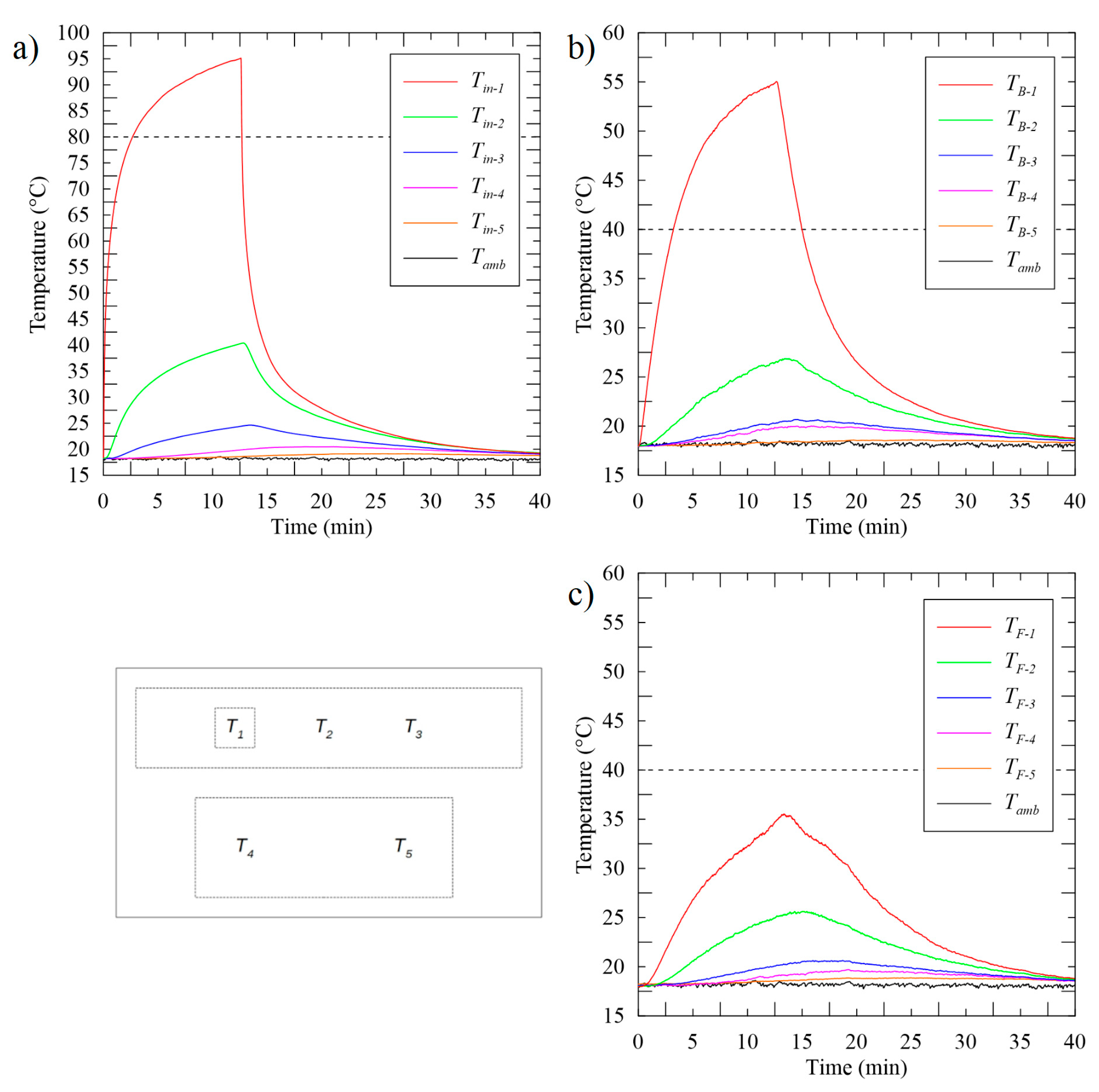
Figure 5 shows the temperatures measured, with a heat generation rate of 4.5 W, (a) inside the mock tablet, (b) on the back cover, and (c) on the front cover. The temperature measured at the heater (
Tin-1) exceeded the high temperature limit for components (80 °C) in 2.6 min, and the cut-off temperature (95 °C) at approximately 12.5 min. The back cover temperature measured just above the heater (
TB-1) exceeded the comfort threshold (40 °C) in 2.7 min. None of the temperatures measured on the front cover exceeded this threshold during the experiment. At a higher heat generation rate of 7 W (
Figure 6), the temperatures measured at the heater (
Tin-1) exceeded 80 °C in under a minute and exceeded 95 °C in just 1.1 min. The mock tablet could only operate for a short time before it overheated. If this was a real tablet, it would have been forced to thermal throttle to avoid damage.
Those results show that the thermal resistance between the heater and other components was high. However, heat was more easily transferred to the back cover, which saw its temperature increase much more than the front cover. It can be concluded that the thermal path going through the screen offers an important thermal resistance in the system. Additionally, for the short duration of each of those tests, the temperatures measured by the thermocouples in positions 3, 4, and 5 barely increased (a maximum increase of approximately 4 °C). This indicates the limited heat spreading potential inherent to the mock tablet without the aid of a temperature control solution.
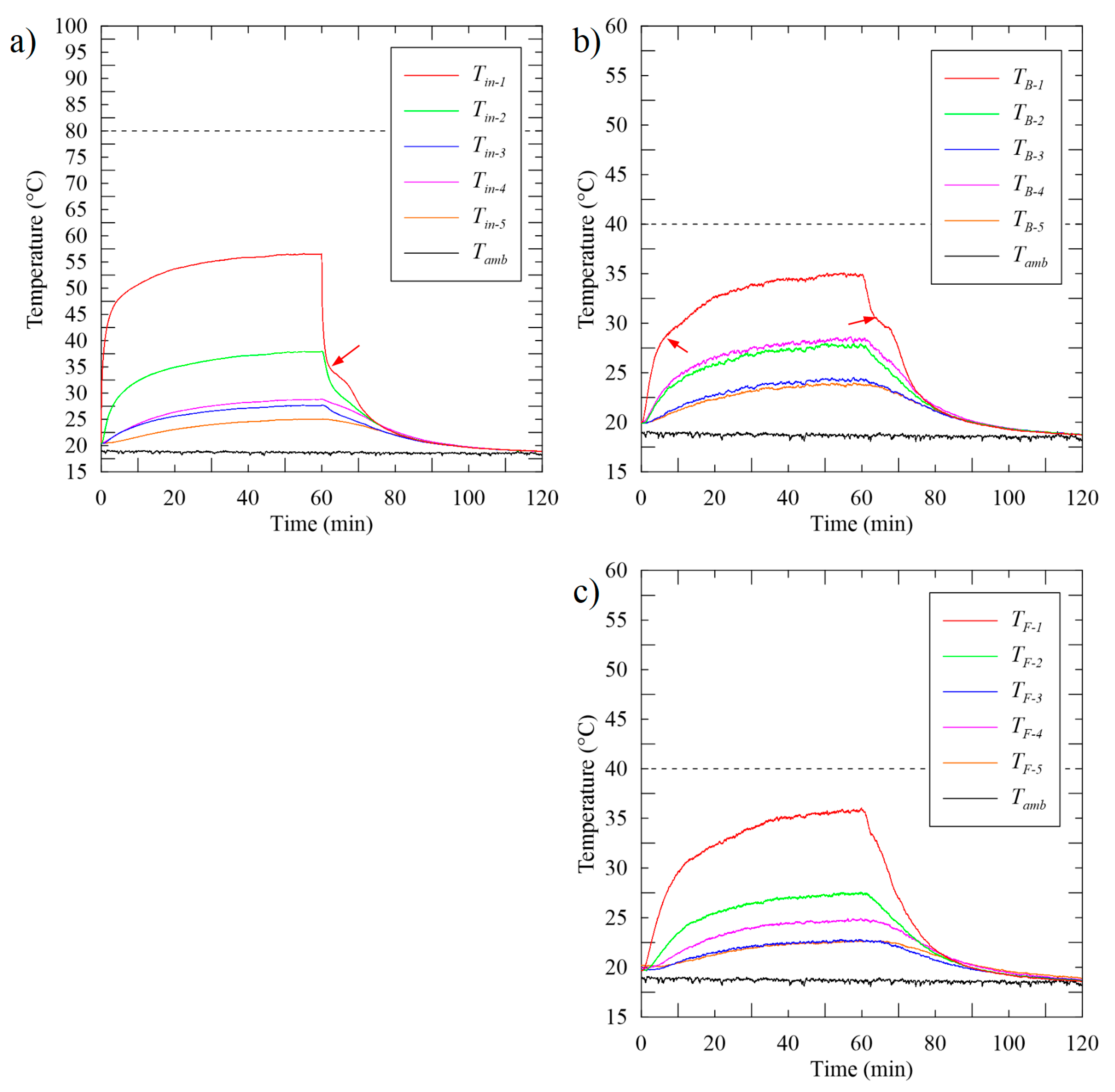
3.2. Mock Tablet with an Aluminum Heat Spreader
Figure 7 shows temperatures measured with an aluminum heat spreader placed against the heater, and a heat generation rate of 4.5 W. The experiment ended after 60 min without temperatures exceeding 95 °C. Temperatures inside the tablet increased slower than without a temperature control solution. The heater exceeded 80 °C after approximately 5.3 min. The maximum back surface temperature did not exceed the comfort threshold and the temperatures were more uniform. The maximum temperature difference measured across the back surface (between
TB-1 and
TB-5) was 8.7 °C. The front surface temperatures were higher than the back surface temperatures (
Figure 7b,c). The temperature distribution on the front cover was not as uniform as that on the back surface and passed the comfort threshold at approximately 24 min. The aluminum spreader, placed between the electronics and the back cover, significantly reduced the peak temperature on the back surface by spreading heat over a larger area. However, it had a smaller impact on the front surface temperatures. This is the opposite of what was observed in the tests without a thermal spreader. The thermal spreader clearly played its role in reducing the peak temperature and spreading the heat on the back cover, but also added a significant thermal resistance in the system that led to the front cover being much warmer.
In a real tablet, the processor would have had to throttle after 5.3 min to keep the SoC cool, and the front cover temperature likely would not have been a problem.
There was an odd inflection in the front cover’s temperature profile. This inflection existed during the heating and cooling phase and appeared to come from latent heat storage, seen at a temperature of approximately 34 °C in
Figure 7c (indicated with red arrows). Although all residual PCM was cleaned from the accessible areas of the display assembly, possibly there is a small amount of PCM imbedded in the display assembly. The inflections are small and would not pose a significant problem for the testing, and only seem to appear in measurements at TF-1. If anything, it makes the findings more conservative as there might have been a small amount of latent heat storage present in the empty comparison cases.
Figure 8 shows temperatures measured under the same conditions but with the inclusion of TIM between the heat spreader and the heater to address the additional thermal resistance observed in the results of
Figure 7. The use of TIM is very impactful.
All temperatures are reduced by the inclusion of TIM, except the back cover temperatures, which were moderately increased as expected by the reduction of this thermal resistance. None of the temperature limits were reached during the 60-min experiment and it is evident that it could operate at this heat generation rate for a long period of time, possibly indefinitely. The temperature sensor just over the heater on the front cover (TF-1) was the closest to reaching its limit.
The TIM reduced the contact resistance between the heater and the heat spreader. For this reason, more of the heat is being directed towards the back of the device. This increased the temperatures on the back surface while reducing it elsewhere. However, by increasing the heat directed into the heat spreader, it increased its impact on the temperature history and significantly improved its overall temperature control effectiveness.
Figure 9 shows temperatures measured with the aluminum heat spreader and a heat generation rate of 7 W. The duration of this test (less than 3 min before reaching the maximum allowed safety temperature) is too short to observe any impact of heat spreading. However, when compared with the test without any temperature control solution, the tablet was operated for twice as long, and the back cover temperature was much lower at the end. Both these observations show the impact of the heat spreader, but also point to the increase in thermal contact resistance.
Figure 10 shows the same experiment with added TIM. With the higher heat generation rate of 7 W, the impact of the TIM is essential to managing the temperature of the mock tablet. Without the TIM, the mock tablet overheats at the heater in 0.8 min. With TIM included, the mock tablet overheats at the front cover after 14.7 min, while the SoC barely reaches its maximum allowed temperature of 80 °C at the very end of the heating phase.
With the two temperature control solutions, the temperatures on the front cover were most critical and the processor would have had to throttle after 14.7 min to keep the front screen below its maximum comfort limit.
3.3. Latent Heat Module
In this experiment, the aluminum heat spreader was placed against the heater and the LHTES module was placed between the heat spreader and the back cover. Although tests were performed without using any TIM, those results are not shown here since, as expected from previous results, the performance was not optimal. For the results presented here, TIM was placed between the heater and the heat spreader.
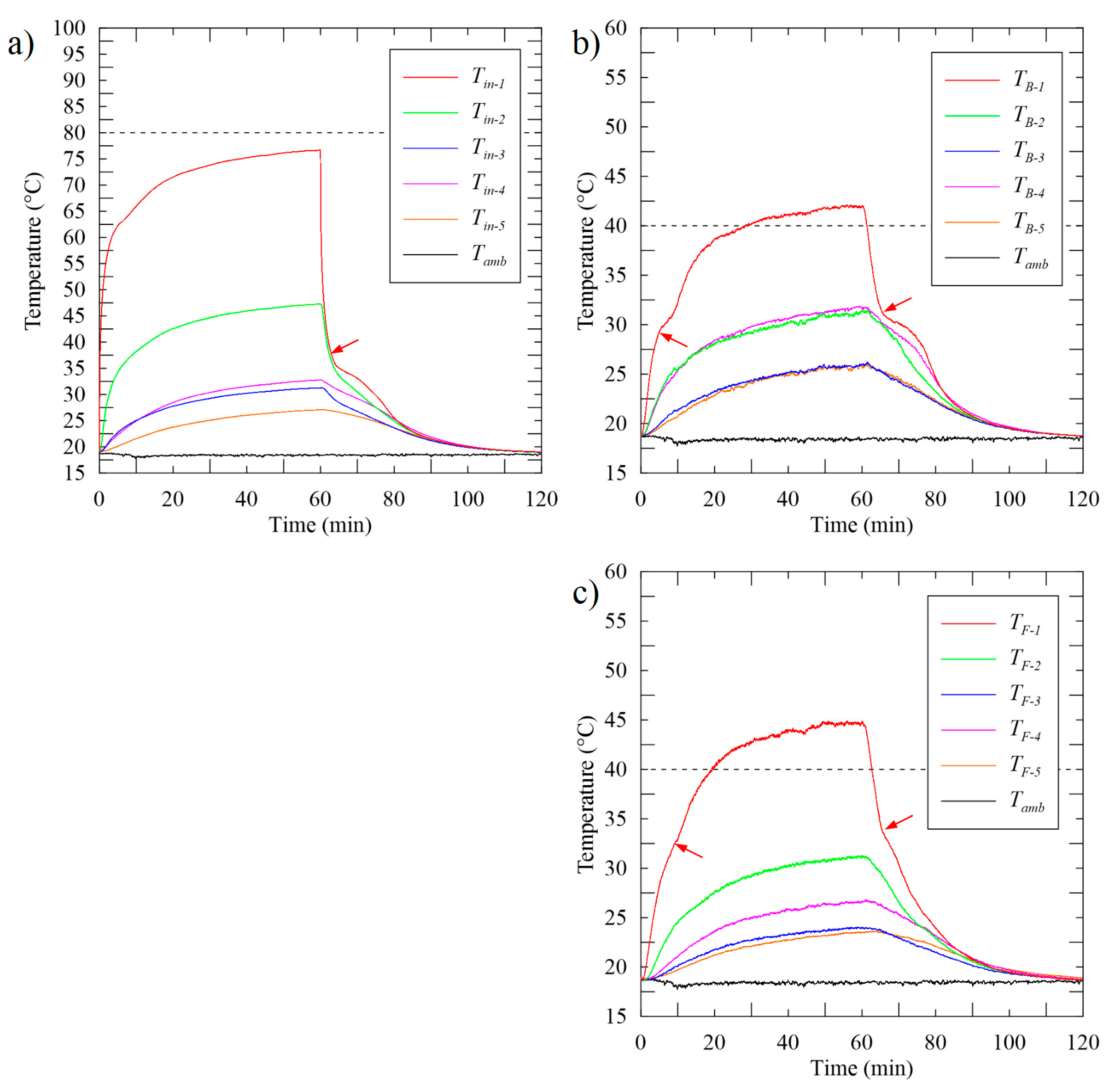
Figure 11 shows the temperatures measured, with a heat generation rate of 4.5 W, (a) inside the mock tablet, (b) on the back cover, and (c) on the front cover. The 60-min heating phase was completed without any measured temperature exceeding 95 °C. Neither the heater temperature nor the tablet surface reached their critical temperature limit.
There was clear evidence of a phase change in this experiment: inflections were observed in the temperature profile inside the mock tablet (Tin-1 and Tin-2) and on the back surface (TB-1) (all indicated with red arrows), and to a lesser extent on the front surface (TF-1). Those inflection points are seen at temperatures lower than the PCM’s melting point (Tm) since the thermocouples are on various surfaces in and on the tablet, and not in thermal contact with the PCM.
It is important to note that it is not possible to estimate the PCM melting fraction in these experiments, as this would require many thermocouples in the PCM package as in Ahmed et al. [
5], or all over its surface as in the work of Maranda et al. [
16]. However, there is significant evidence that the LHTES module was storing heat and positively influencing the temperature control of the mock tablet computer when comparing the temperature history in
Figure 11 to
Figure 8; lower or equivalent temperatures at every point clearly indicate that the excess energy has been stored in the LHTES.
Figure 12 shows the temperatures measured with the LHTES, a heat spreader, TIM, and a heat generation rate of 7 W. The 60-min heating phase was completed. There was again clear evidence of phase transition: inflections in many of the temperature profiles (again indicated with red arrows). The heater temperature did not exceed the SoC maximum temperature. The back surface temperature exceeded the comfort limit after approximately 28 min, while the front exceeded the comfort temperature after approximately 19 min.
4. Discussion
Figure 13 shows the temperature history for the sensors that measured the highest peak temperature (
Tin-1,
TB-1, and
TF-1) on the inside, back cover, and front screen, respectively. Measurements from the experiment with the heat spreader and TIM are compared with those of the heat spreader, TIM, and LHTES module.
The inclusion of the LHTES module reduced the peak temperatures measured inside and on the screen of the mock tablet, while having little impact on the temperatures measured on the back cover. This indicates that the addition of the LHTES increased the rate of heat transfer towards the back cover (lowering the temperature of the SoC and the front screen) while maintaining the back cover at the same temperature through the storage of the additional heat through the PCM.
However, peak temperature is not the best measure of the effectiveness of a temperature control solution. There are two core objectives of a temperature control solution in handheld electronics. The first is to extend the operating time before the device reaches a temperature limit and is required to throttle the processor speed. The second is to reduce the mean operating temperature of the major sources in the system, increasing the life of these components. The LHTES module improved both these aspects in the mock tablet computer.
The cooling phase of the experiment was also impacted by the LHTES module. The inflection in the temperature profile due to latent heat storage reduced the cooling rate, keeping the tablet near the transition temperature as the PCM solidified. However, after the PCM solidified, the temperature quickly approached the temperature profile of the experiments without latent heat storage. Additionally, all experiments showed the tablet cooling to ambient in just under 60 min.
Table 4 summarizes the time required for the device to reach its maximum allowed operating temperature, either at the heater or the front surface. Entries in the table showing dashes indicate that the feature did not reach its limiting temperature during a 60-min experiment. Longer times show superior performance since the tablet will be able to operate with thermal throttling for a longer period.
At a heat generation of 4.5 W, the two temperature control solutions that utilize TIM are by far the best solutions as neither reached their temperature limits within the 60-min time. Without the TIM, the device’s SoC overheated in less than a minute when a heat generation rate of 7 W was used. The use of the TIM greatly reduced the thermal contact resistance between the SoC and the heat spreader, moving the location of the temperature limit reached to the front cover.
At 7 W, the solution using the heat spreader, TIM, and LHTES led to an approximately 30% increase in operating time before the critical temperature (on the front surface) was reached, compared with the case without a LHTES.
5. Conclusions
An experimental platform was used to investigate the integration of solid–liquid LHTES modules into the temperature control system of modern and future handheld electronics. A mock tablet was used to record the temperature history in various positions in the device during experiments utilizing different temperature control solutions.
The temperature history with an aluminum spreader was compared with that of an aluminum spreader with an n-eicosane-based LHTES module. It was first shown that thermal contact resistances are important in such a device, and that the use of TIM between the heater and the thermal spreader played a very important role in the heat transfer within the device. With the TIM and the spreader, it was shown that the LHTES module had a significant impact on the thermal response of the handheld device, reducing the mean and peak temperature of the device’s components and increasing the time it can operate without reaching a threshold temperature on the surface (40 °C) or the components (80 °C). Without the LHTES module (with a heat rate of 7 W), the front surface (display) temperature reached the comfort limit after 14.7 min. After the addition of the LHTES module, the front surface reached the comfort limit after 19.2 min, and thus the LHTES module increased the safe operating time by approximately 30%.
These findings are promising for the use of LHTES modules to enhance the performance of modern portable electronics, but the results are not transferable to all situations. Based on the present results, for lower power situations (4.5 W), the heat spreader and TIM are sufficient, and the impact of the LHTES module was limited to lowering the mean and peak temperature of the tablet components, which is still important in maximizing the lifetime of the electronic components. Additionally, LHTES modules require PCMs selected and optimized for the circumstances. At higher heat generation rates, the thermal storage in the LHTES modules used in this work would become insufficient. Further gains could potentially be made if the LHTES module could be made thicker. However, improving heat spreading to transport heat to all corners of the LHTES module is the most promising direction for further improvements.


