Article

Moving Vehicle Tracking with a Moving Drone Based on Track Association

School of ICT Eng., Daegu University, Gyeongsan 38453, Korea
*
Author to whom correspondence should be addressed.
Appl. Sci. 2021, 11(9), 4046; https://doi.org/10.3390/app11094046
Submission received: 26 February 2021 / Revised: 23 April 2021 / Accepted: 27 April 2021 / Published: 29 April 2021
(This article belongs to the Special Issue Intelligent Processing on Image and Optical Information, Volume II)

Abstract

:
The drone has played an important role in security and surveillance. However, due to the limited computing power and energy resources, more efficient systems are required for surveillance tasks. In this paper, we address detection and tracking of moving vehicles with a small drone. A moving object detection scheme has been developed based on frame registration and subtraction followed by morphological filtering and false alarm removing. The center position of the detected object area is the input to the tracking target as a measurement. The Kalman filter estimates the position and velocity of the target based on the measurement nearest to the state prediction. We propose a new data association scheme for multiple measurements on a single target. This track association method consists of the hypothesis testing between two tracks and track fusion through track selection and termination. We reduce redundant tracks on the same target and maintain the track with the least estimation error. In the experiment, drones flying at an altitude of 150 m captured two videos in an urban environment. There are a total of 9 and 23 moving vehicles in each video; the detection rates are 92% and 89%, respectively. The number of valid tracks is significantly reduced from 13 to 10 and 56 to 26 in the first and the second video, respectively. In the first video, the average position RMSE of two merged tracks are improved by 83.6% when only the fused states are considered. In the second video, the average position and velocity RMSE are 1.21 m and 1.97 m/s, showing the robustness of the proposed system.

1. Introduction

In recent years, the use of a small unmanned aerial vehicle (UAV) or drone is increasing in various applications [1]. Aerial video surveillance is of particular interest among the applications [2]. Multirotor drones can hover or fly as programmed while capturing video from a distance [3]. This capture is cost effective and does not require highly trained personnel. However, the limited computational power of a small drone is an important factor that must be considered.
When the drone moves, the coordinates change as the surveillance coverage is shifted. Therefore, the frame registration is required to generate fixed coordinates. The registration process matches multiple images from varying scenes to the same coordinates [4]. Coarse-to-fine level image registration was proposed in [5]. Frames from different sensors was registered via modified dynamic time warping in [6]. Telemetry-assisted registrations of frames from a drone were studied in [7]. In [8], the drone velocities were estimated using frame registration based on sum of absolute difference (SAD).
Studies on target tracking with a small drone have been conducted with various methods. They can be categorized as visual, non-visual, or combined trackers. The visual trackers by a small drone mainly utilizes video streams. One is tracking with deep learning. In [9], various deep learning-based trackers were compared with a camera motion model. Testing results with UAV-based real video showed that small objects, large numbers of targets, and camera motion degraded tracking performance even using high-end CPUs [10]. The deep learning-based object detector and tracker require heavy computation with massive training data [11,12], thus real-time processing can often be an issue to solve.
The other is based on conventional image processing techniques. In [13], the moving objects are detected by background subtraction and the continuously adaptive mean-shift tracking and the optical flow tracking were applied to the video sequences acquired by the UAV. The particle filtering combined with the mean-shift method was developed to track a small and fast-moving object in [14]. A correlation-based tracker was proposed to track ground objects at low altitudes [15]. These methods also need to transmit high resolution video streams to the ground or impose high computing on the drone. Indeed, the visual trackers rarely evaluate the kinematic state of the target, such as position and velocity. The initial location, target size, and number of targets are often assumed to be known to the visual tracker. The tracking of high-resolution objects has been studied in [16,17], but they are not suitable for wide range surveillance.
The accurate position of the target can be obtained with non-imaging sensing data such as radar signals [18]. In [19], aerial video processing has been combined with the high-precision GPS data from vehicles. Bayesian fusion of vision and radio frequency sensors were studied for ground target tracking [20]. However, in those methods, the drone or vehicles should be equipped with high-cost sensors that add more payload to the drone.
Multiple targets are tracked by continuously estimating their kinematic state such as position, velocity, and acceleration. Highly maneuvering, closely located targets, heavy clutters, and low detection probability are challenges in multiple target tracking [21]. The Kalman filter is known to be optimal under independent Gaussian noise assumption in estimating the target state [22]. The interacting multiple model (IMM) estimator was developed [23] and successfully applied to handle multiple targets in high maneuvering [24].
Data association, which assigns measurements to tracks, is also an important task for tracking multiple targets in a clutter environment. The nearest neighbor (NN) measurement–track association is the most effective in computing and has been successfully applied to precision target tracking based on multiple frames [25,26,27]. The Bayesian data association approach, probabilistic data association (PDA) and joint PDA (JPDA), makes a soft decision on validated measurements using the association probability between the target and the measurement [21]. However, in the scheme, the tracks should be initialized in advance with prior knowledge of the number of targets. An efficient sub-event tracker based on the IMM-JPDA approach was proposed to reduce the computational load in [28]. Another Bayesian approach with hard decision, multiple hypotheses tracking (MHT) [29], requires hypothesis reduction due to exponentially increasing computational complexity. The probabilistic MHT (PMHT) was developed as soft association in [30]. In the scheme, the computational load increases linearly in the number of measurements and targets, but the number of targets should be known and fixed. The closed-form solution of the PMHT was proposed as the Gaussian Mixture PHD (GMPHD) in [31]. A non-Bayesian data association approach, N-dimension assignment, has been developed to make hard decision on the measurement [32]. However, the assignment technique assumes that, at most, one measurement is detected on a single target. When multiple sensors are available, the track-to-track fusion method has been developed, assuming multiple tracks arise from the common process noise of the target [21]. Various track-to-track fusion methods have been studied and verified in [33,34].
In the paper, we address the detection and tracking of moving vehicles with a moving drone. Considering the limited computing power and communication resources of small drones, the drone surveillance system is configured as shown in Figure 1. In one case, a singe drone processes both moving object detection and multiple target tracking using an onboard computer. The kinematic states of the target or a simple alert signal is transmitted to the ground. In another case, moving object detection is performed on the drone instantly after video capture, and then the center positions of the extracted object areas are transmitted to the ground control station to perform multiple target tracking. In the latter, it is possible to associate the measurements of multiple drones with the proposed association method. Since the proposed scheme does not use intensity information with heavy computation, there is no need to store or transmit a high-resolution video stream.
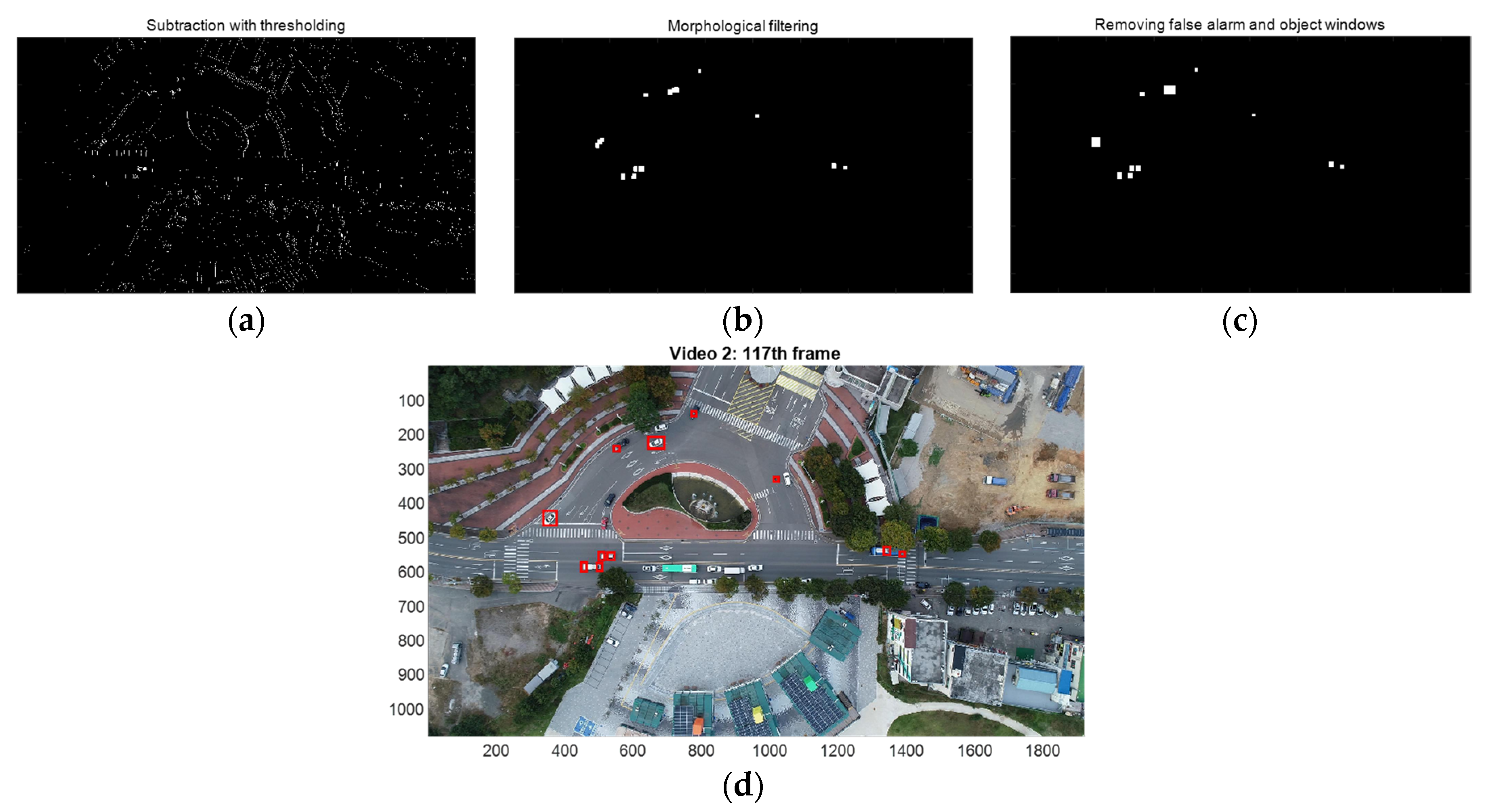
During moving object detection, frame registration is performed between two consecutive frames to compensate for the drone’s movement [8]. The current frame compensated for and subtracted from the previous frame, and thresholding is performed to generate a binary image of the moving object. Two morphological filters (erosion and dilation) are applied sequentially to the binary image. The erosion filter removes very small clutters, and the dilation filter restores the boundaries of the object areas and connects fragmented areas of one object. Finally, target blobs smaller than the assumed target size are removed. The center location of the target area becomes the measurement of the next tracking stage.
The tracking is performed by the Kalman filter to estimate the kinematic state of the target following the moving object detection. A nearly constant velocity (NCV) motion model is used as the discrete time kinematic model for the target. The NCV model has been successfully applied to the aerial early warning system to track 120 aerial targets with high maneuvers up to 6 g [24] and other applications [34,35,36].
The track is initialized by the two-point differential initialization following the maximum speed gating process. The initial state of the track can affect tracking performance severely. In the proposed scheme, no additional process for the initialization is required.
For measurement of track association, a position gating process excludes measurements outside the validation region. Then, the NN association assigns valid measurements to tracks. However, multiple tracks can be generated if multiple measurements on a single target are detected [27]. In the paper, we propose a new association scheme, track–track association, in order to maintain a single track for each target. In the proposed method, first, it is an association test of two tracks that performs hypothesis testing using chi-square statistics, which is the statistical distance between estimates of the current state of the two tracks. Second, the track with the smallest determinant of the covariance matrix of the state is maintained and the other is terminated. It is noted that covariance measures the expected value of the squared error between the true state and the unbiased estimate. Finally, the last update of the selected track is replaced by the fused estimate.
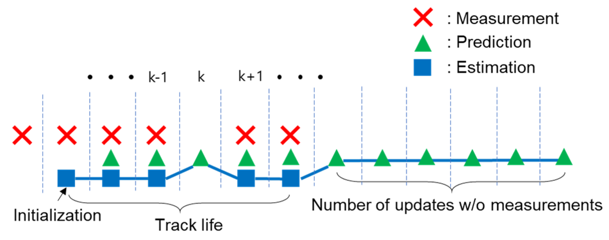
We also set the criteria for a valid track and the termination of the track. A track is confirmed as a valid track if it continues longer than the minimum track life, and a track is terminated after searching for the measurements for a certain number of allowed frames.
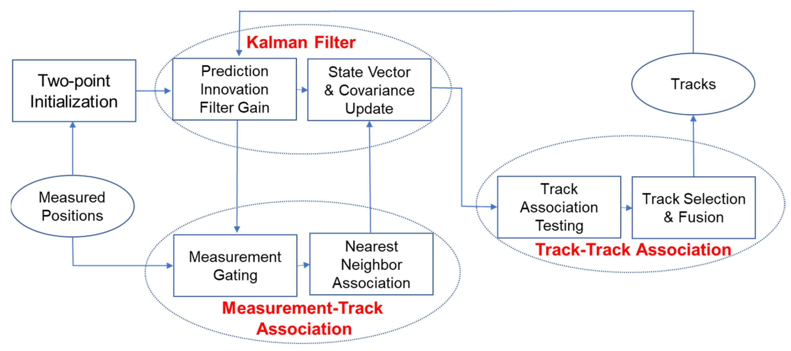
In the experiments, the drones captured two videos while flying at a height of 150 m in an urban environment. The drone camera pointed directly downwards. In each video, there are a total of 9 or 23 moving vehicles (cars, buss, motorcycles, and bicycles), respectively. With the proposed association, the number of valid tracks was reduced from 13 to 10 in the first video and 56 to 26 in the second video. In the first video (Video 1), considering only the fusion state of the two targets, the sum of the position RMSE decreased from 5.2 m to 0.85 m, showing a reduction rate of about 83.6%. In the second video (Video 2), the average position and velocity RMSEs are 1.21 m 1.97 and m/s, respectively, showing the accuracy of the proposed system. Figure 2 shows a block diagram of the moving vehicle detection and multiple target tracking.
The contributions of this paper are listed as follows: (1) we propose a new data association scheme. The proposed track–track association is utilized with the NN measurement–track association. The track association is based on the least covariance matrix while the NN association is based on the least statistical distance. Therefore, the proposed data association is easy to implement and provides fast computing. The experimental results show that the proposed method is very effective when multiple measurements are detected on a single target in consecutive frames. (2) The moving object detection-multiple target tracking scheme is studied with a moving drone. In the previous studies, the video is captured with a drone hovering at a fixed position. However, as the drone flies, the coverage of surveillance expands by utilizing the drone as a dynamic sensor. A moving drone has a wider range of surveillance at higher altitudes and at higher speeds, which degrades image resolution and quality. Through the experiments, the proposed scheme was applied to small size objects at slow-rate frame videos (10 fps). (3) We propose a new configuration of drone surveillance as shown in Figure 1. Small drones have limited computational resources in CPU, memory, battery, and bandwidth. We can build a more efficient surveillance system where storage or transmission of high-resolution video streams is not essential.
The remainder of the paper is organized as follows: object detection is discussed in Section 2. Section 3 demonstrates multiple target tracking. Section 4 presents experimental results, and the conclusion follows in Section 5.

2. Moving Object Detection

This section briefly describes the moving object detection with a moving drone studied in [8]. Moving object detection consists of frame registration and subtraction followed by thresholding, morphological operations, and removing false alarms. Two consecutive gray-scaled images Ik and Ik−1 are registered using the SAD between them. The SAD at k-th frame is obtained as
S A D k ( p x , p y ) = n = 1 N m = 1 M | I k ( m + p x , n + p y ) I k 1 ( m , n ) | , k = 2 , , K ,
where M and N are the image sizes in the x and y directions, respectively; K is the total number of frames. The displacement vectors px and py are obtained in the x and y directions, respectively, by minimizing the SAD as
[ p ^ x ( k )   p ^ y ( k ) ] = m i n ( p x p y ) S A D k ( p x , p y ) .
The subtraction and thresholding generate a binary image after the coordinate compensation as
B k ( m , n ; k ) = { 1 , i f | I k ( m + p ^ x ( k ) , n + p ^ y ( k ) ) I k 1 ( m , n ) |   θ T 0 , o t h e r w i s e } ,
where θ T is a threshold value set to 85 and 30 for Video 1 and 2, respectively, in the experiments. Two morphological operations, erosion and dilation, are sequentially applied to the binary image. The structure elements for erosion and dilation are set at [ 1 ] 2 × 2 and [ 1 ] 20 × 20 , respectively. Finally, assuming the true size of the object is known, the false alarm is removed as
O i ( m , n ) = { 1 ,   size { O i } > θ s 0 ,   o t h e r w i s e } ,
where Oi is the i-th object area, and θs is the minimum object size, set to 400 or 100 for Video 1 and 2, respectively, in the experiments.

3. Multiple Target Tracking

A block diagram of multiple target-tracking with the new association scheme is shown in Figure 3. Each step of the block diagram is described in the following subsections.

3.1. System Modeling

The kinematic state of a target is assumed to follow a nearly constant velocity (NCV) motion. The uncertainty of the process noise, which follows the Gaussian distribution, controls the kinematic state of the target. The discrete state equation for multiple targets is as follows
x t ( k + 1 ) = F ( Δ ) x t ( k ) + q ( Δ ) v ( k ) ,   t = 1 ,   ,   N T ,  
F ( Δ ) = [ 1 Δ 00 0100 001 Δ 0001 ] , q ( Δ ) = [ Δ 2 / 20 Δ   0 0 Δ 2 / 2 0 Δ ]
where x t ( k ) = [ x t ( k ) v t x ( k ) y t ( k ) v t y ( k ) ] T is the state vector of target t at frame k, xt(k) and yt(k) are positions in the x and y directions, respectively; vtx(k) and vty(k) are velocities in the x and y directions, respectively; NT is the number of targets, Δ is the sampling time, and v(k) is a process noise vector, which is Gaussian white noise with the covariance matrix Q v = d i a g ( [ σ x 2 σ y 2 ] ) . The measurement vector for target t consists of the positions in the x and y directions. The measurement equation is as follows
z t ( k ) = [ z t x ( k ) z t y ( k ) ] = H x t ( k ) + w ( k ) ,
H = [ 1000 0010 ] ,
where w(k) is a measurement noise vector, which is Gaussian white noise with the covariance matrix R = d i a g ( [ r x 2 r y 2 ] ) .

3.2. Two Point Intialization

Two-point initialization has been applied to target tracking by a drone [25,26,27]. The initial state of each target is calculated by the two-point differencing following a maximum speed gating. The initial state vector and covariance matrix for target t are, respectively:
x ^ t ( k | k ) = [ x ^ t ( k | k ) v ^ t x ( k | k ) y ^ t ( k | k ) v ^ t y ( k | k ) ] = [ z t x ( k ) z t x ( k ) z t x ( k 1 ) Δ z t y ( k ) z t y ( k ) z t y ( k 1 ) Δ ]   ,   P t ( k | k ) = [ r x 2 r x 2 Δ 0 0 r x 2 Δ   2 r x 2 Δ 2   0 0 0   0 r y 2 r y 2 Δ 0   0 r y 2 Δ 2 r y 2 Δ 2 ]
The state is confirmed as the initial state of the track if the following speed gating is satisfied: [ v ^ t x ( k | k ) ] 2 + [ v ^ t y ( k | k ) ] 2 V m a x , where Vmax is the maximum speed of the target.

3.3. Prediction and Filter Gain

The state and covariance predictions are iteratively computed as
x ^ t ( k | k 1 ) = F x ^ t ( k 1 | k 1 ) ,
P t ( k | k 1 ) = F P t ( k 1 | k 1 ) F T + Q ,
Q = q ( Δ ) Q v q ( Δ ) T ,
where x ^ t ( k | k 1 ) and P t ( k | k 1 ) , respectively, are the state and the covariance prediction of target t at frame k; T denotes the matrix transpose. The residual covariance S t ( k ) and the filter gain W t ( k ) , respectively, are obtained as
S t ( k ) = H P t ( k | k 1 ) H T + R ,
W t ( k ) = P t ( k | k 1 ) H T S t ( k ) 1 .

3.4. Measurement–Track Association

Measurement to track association is the process of assigning measurements to established tracks. The measurement gating is performed by the chi-square hypothesis test assuming Gaussian measurement residuals [21]. The measurement in the validation region is considered candidates for the target t at frame k as
Z t ( k ) = { z m ( k ) | ν t m ( k ) T [ S t ( k ) ] 1 ν t m ( k ) γ g , m = 1 , , M ( k ) } ,
ν t m ( k ) = z m ( k ) H x t ( k | k 1 ) ,
where zm(k) is the m-th measurement vector at frame k, γ g is the gating size for measurement association, and M(k) is the number of measurements at frame k. The NN association rule assigns track t to the m ^ t k -th measurement, which is obtained as
m ^ t k = arg   min m = 1 , , m t ( k )   | | ν t m ( k ) T [ S t ( k ) ] 1 ν t m ( k ) | | ,
where mt(k) is the number of valid measurements for target t at frame k. Any remaining measurements that fail to associate with the target go to the initialization stage in Section 3.2.

3.5. State Estimate and Covariance Update

The state estimate and the covariance matrix of targets are updated as follows:
x ^ t ( k | k ) = x ^ t ( k | k 1 ) + W t ( k ) ν t m ^ t k ( k ) ,
P t ( k | k ) = P t ( k | k 1 ) W t ( k ) S t ( k ) W t ( k ) T .
If no measurement can be associated with target t at frame k, they merely become the predictions of the state and the covariance as
x ^ t ( k | k ) = x ^ t ( k | k 1 ) ,
P t ( k | k ) = P t ( k | k 1 ) .

3.6. Track–Track Association

If multiple measurements are continuously detected on a single object, more than one track can be generated. We develop the track–track association to eliminate redundant tracks. Multiple tracks on the same target have the error dependencies on each other, thus the following track-association hypothesis testing [21] is preceded as
[ x ^ s ( k | k ) x ^ t ( k | k ) ] T [ T s t ( k ) ] 1 [ x ^ s ( k | k ) x ^ t ( k | k ) ] T γ f ,   s , t = 1 , , N ( k ) , s t
T s t ( k ) = P s ( k | k ) + P t ( k | k ) P s t ( k | k ) P t s ( k | k )
P s t ( k | k ) = [ I b s ( k ) W s ( k ) H ] [ F P s t ( k 1 | k 1 ) F T + Q ] [ I b t ( k ) W t ( k ) H ]
where x ^ s ( k | k ) and x ^ t ( k | k ) are the state vector of track s and k, respectively, at frame k; P s ( k | k ) and P t ( k | k ) are the covariance matrix of track s and k, respectively, at frame k; γ f is a thresholding value for track association; N(k) is the number of tracks at frame k; bs(k) and bt(k) are binary numbers that become one when track s or t is associated with a measurement. If there is no measurement associated, it will be zero. In this case, the state vector and the covariance matrix are replaced by predictions as in Equations (20) and (21). The fused covariance in Equation (24) is a linear recursion and its initial condition is set at P s t ( 0 | 0 ) = [ 0 ] 4 × 4 . When the track association hypothesis is accepted, the most accurate track is selected, the current state is replaced with a fused estimate, and the remaining track is immediately terminated. The selection process is based on the determinant of the covariance matrix because the more accurate track has less error (covariance). A track is selected and fused as
c ^ = a r g m i n s , t [ | P s ( k | k ) | , | P t ( k | k ) | ] ,
x ^ c ^ ( k | k ) = x ^ s ( k | k ) + [ P s ( k | k ) P s t ( k | k ) ] [ P s ( k | k ) + P t ( k | k ) P s t ( k | k ) P t s ( k | k ) ] 1 [ x ^ t ( k | k ) x ^ s ( k | k ) ] ,
P c ^ ( k | k ) = P s ( k | k ) [ P s ( k | k ) P s t ( k | k ) ] [ P s ( k | k ) + P t ( k | k ) P s t ( k | k ) P t s ( k | k ) ] 1 [ P s ( k | k ) P t s ( k | k ) ] .
Figure 4 illustrates the track–track association process. Assuming that there are two tracks on the same target at frame k as shown in Figure 4a, the statistical distance between the tracks is tested as shown in Figure 4b. In Figure 4c, the track with the least determinant of the covariance matrix, which is track s, is selected. The state and covariance of track s are replaced by fused ones and the other track t is terminated at the same time.
In the paper, we establish criteria for a valid track and track termination, respectively. One is the minimum track life to become a valid track. Track life is the number of frames between the last frame updated by a measurement and the initial frame [24]. Another criterion is for track termination. The track is terminated if the search for a measurement for a specific number of frames fails. In Figure 5, the track life is six frames, and the track is terminated after six frames without updating measurements.

4. Results

4.1. Video Description

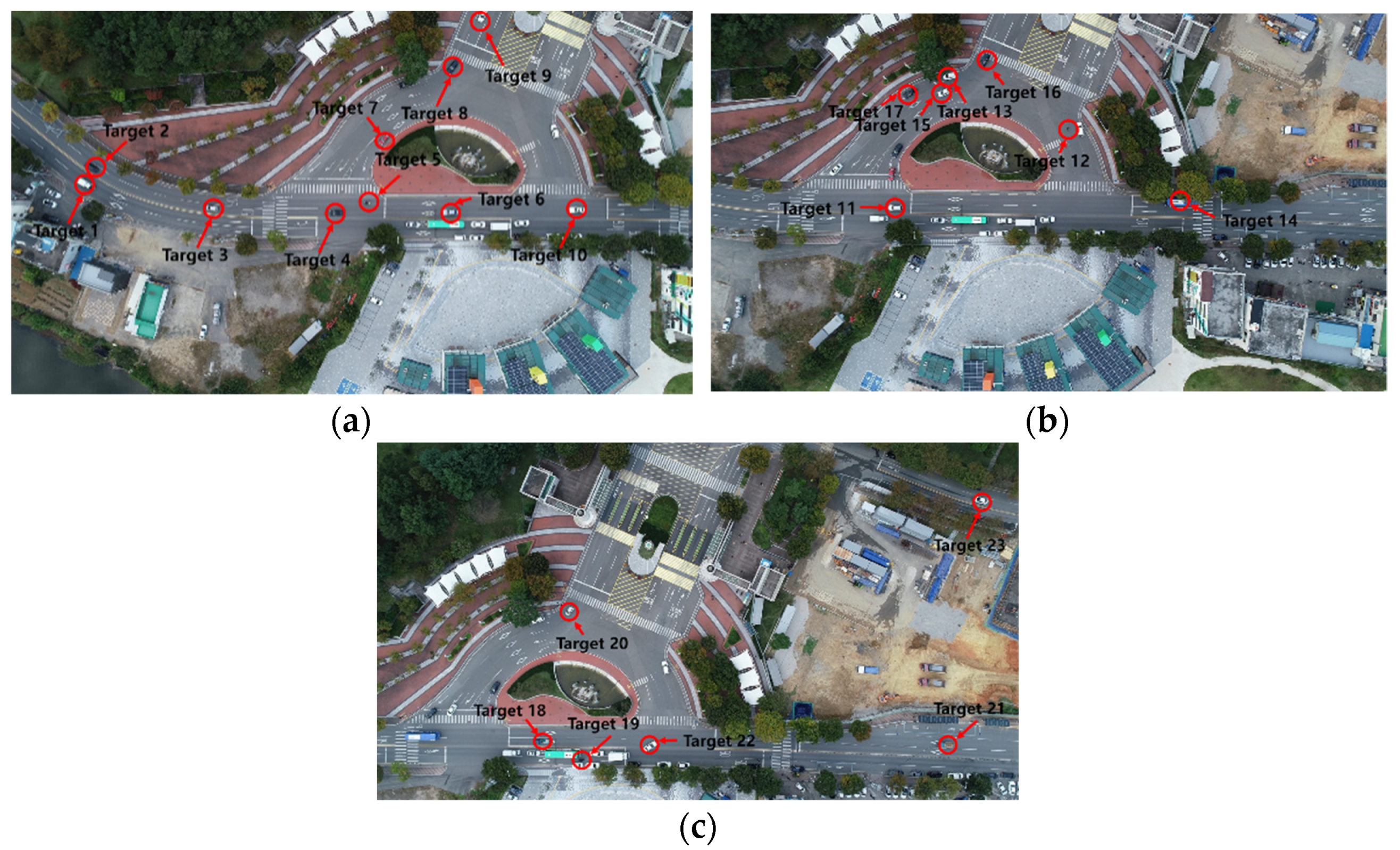
Videos 1 and 2 were captured by a DJI Phantom 4 and Inspire 2 in urban environments, respectively. The drones flew at the height of 150 m in a straight line in Video 1 [8] and changed direction once in Video 2. The videos were captured in different weather and lighting conditions. The drone’s speed was set to be constant on the controller by the operator. The camera was pointed directly at the ground and captured video clips at 30 fps for 15 and 24 s in Videos 1 and 2, respectively. It is processed every third frame for efficient image processing, so a total of 151 and 242 frames are considered in each video and the actual frame rate is 10 fps. The original frame size of Video 1 is 4096 × 2160 pixels, but the frame is gray-scaled and resized by 50% to reduce the computational time. In Video 2, the original frame of 3840 × 2160 pixels is scaled the same way. One pixel corresponds to 0.11 m after resizing. There are 9 moving vehicles (6 cars, 2 buses, 1 bike) and several pedestrians in Video 1 while there are 23 moving vehicles (18 cars, 2 buses, 2 motorcycles, 1 bicycle) in Video 2. The details of the videos are described in Table 1.
Figure 6a shows Targets 1–6 at the 54th frame of Video 1, and Figure 6b shows Targets 7–9 at the 131st frame. The drone flew slightly upwards from west to east, and the coverage of the frame continued to shift in the same direction. Figure 7a shows Targets 1–10 at the 7th frame of Video 2, Figure 7b shows Targets 11–17 at the 117th frame, and Figure 7c shows Targets 18–23 at the 218th frame. The drone flew west to east for 130 frames and north for the remaining 111 frames in Video 2.

4.2. Moving Object Detection

The coordinates of the frame were compensated for and then, frame subtraction was performed between the current and the preceding frames as in Equation (3). Figure 8 shows the intermediate results of the detection process of Figure 6b. Figure 8a is the binary image generated by frame subtraction and thresholding. Figure 8b is the object area after morphological operations (erosion and expansion) are applied to Figure 8a. Figure 8c shows the rectangular windows including the detected area after false alarm removal in Figure 8b. The red bounding boxes in Figure 8d are the boundaries of the object windows. Figure 9 shows the detection results of Figure 7b.
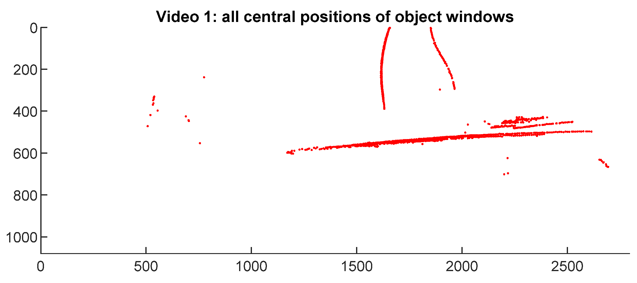
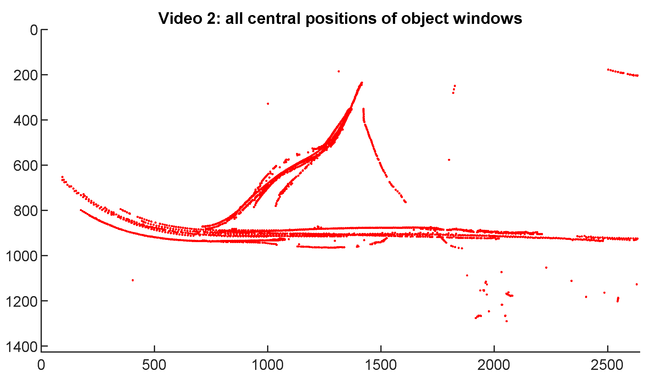
The average detection rate of Video 1 is 92%. A total of 23 false alarms were detected including 16 moving pedestrians, but the pedestrians were not considered targets of interest in this study. The average detection rate of Video 2 is 89%. There were 47 false alarms, of which 4 moving pedestrians were detected. All the centroids of the object windows including false alarms of Video 1 and 2 are shown in Figure 10 and Figure 11, respectively, in the expanded frame. The number of detections is 709 and 1016 for each video, respectively. The expanded frame of Video 1 is 2779 × 1096 pixels, equivalent to 305.7 × 120.6 m; Video 2 is 2641 × 1426 pixels, equivalent to 290.5 × 156.7 m. The position coordinates of the expanded frame are compensated by [ p ^ x ( k )   p ^ y ( k ) ] obtained in Equation (2). It is noted that the center locations are input to the next target tracking stage as measurements.

4.3. Multiple Target Trackig

In this subsection, we show the target tracking results of Videos 1 and 2. The sampling time in Equation (6) is 0.1 s because every third frame is processed. The parameters are designed as in Table 2.

4.3.1. Tracking Results of Video 1

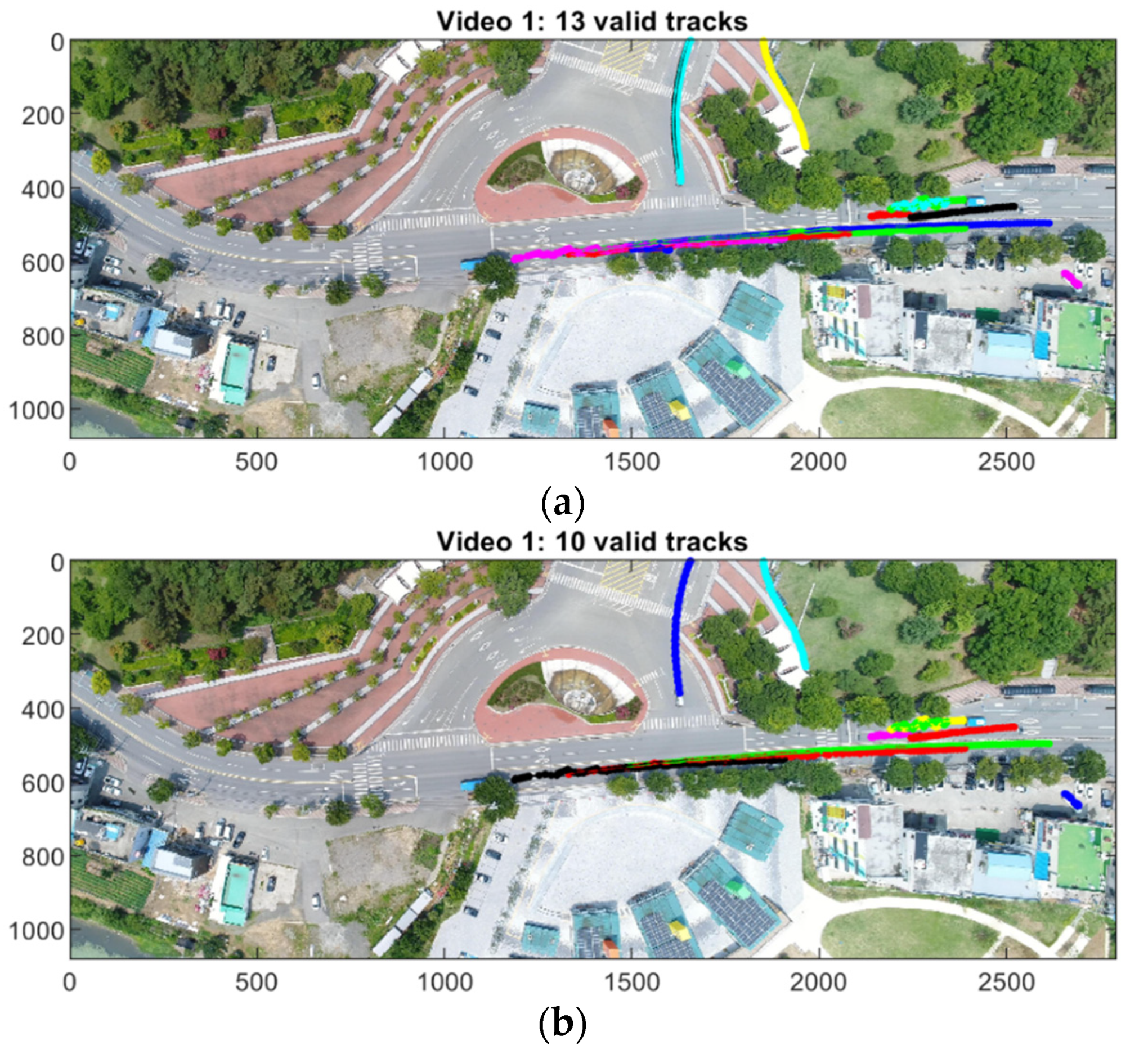
In Video 1, a total of 13 valid tracks are generated without track association; four redundant tracks are generated for Targets 1, 3, 4, and 7. With track association, 3 of the 4 tracks are successfully merged, resulting in 10 valid tracks. Therefore, tracking efficiency was improved from 69% to 90%. Figure 12a,b show the tracking results without and with track association, respectively, in the expanded frame. Two supplementary multimedia files (MP4 format) for tracking vehicles are available online. One is target tracking without track association (Supplementary Material Video S1) and the other is using the proposed method (Supplementary Material Video S2). The red bounding boxes of the MP4 file are the boundaries of the object windows, the blue dots are position estimates, and the numbers represent the track numbers in the order they were created.
Figure 13, Figure 14 and Figure 15 show the fusion results by presenting detailed trajectories of targets 1, 2, and 4, respectively. Two split tracks are merged into one track for Targets 1, 3, and 4. However, no association occurred on track 7 in Figure 16.
To evaluate the accuracy of the position and velocity estimates, the ground truth of the target position for Video 1 is manually obtained as shown in Figure 17. The ground truth of the velocity is obtained as the difference in position between consecutive frames divided by the sampling time.
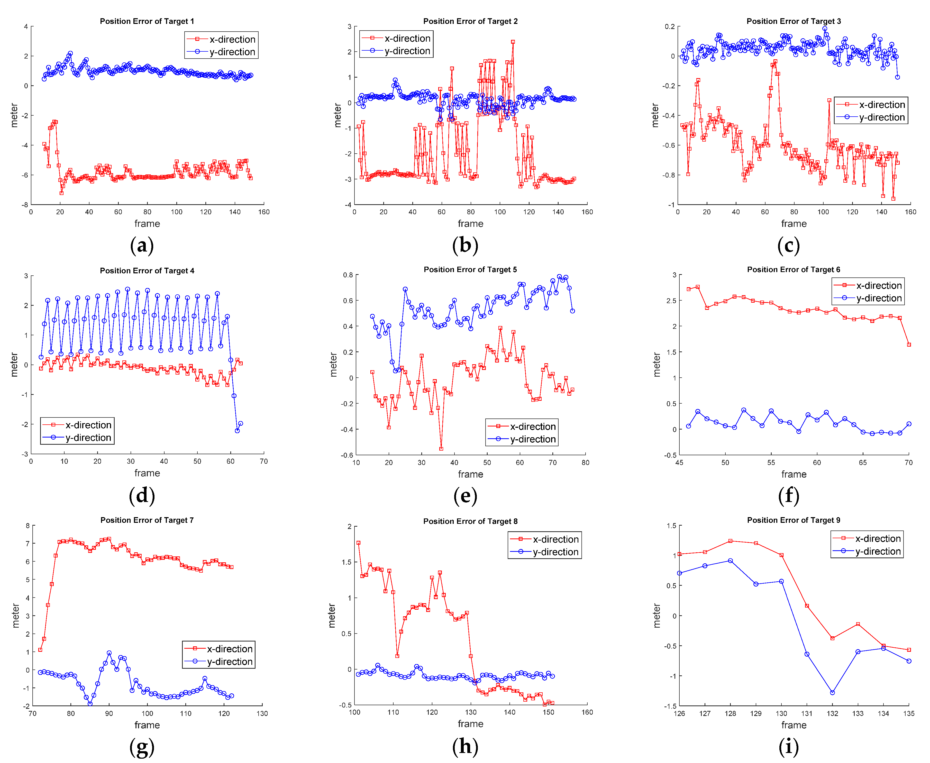
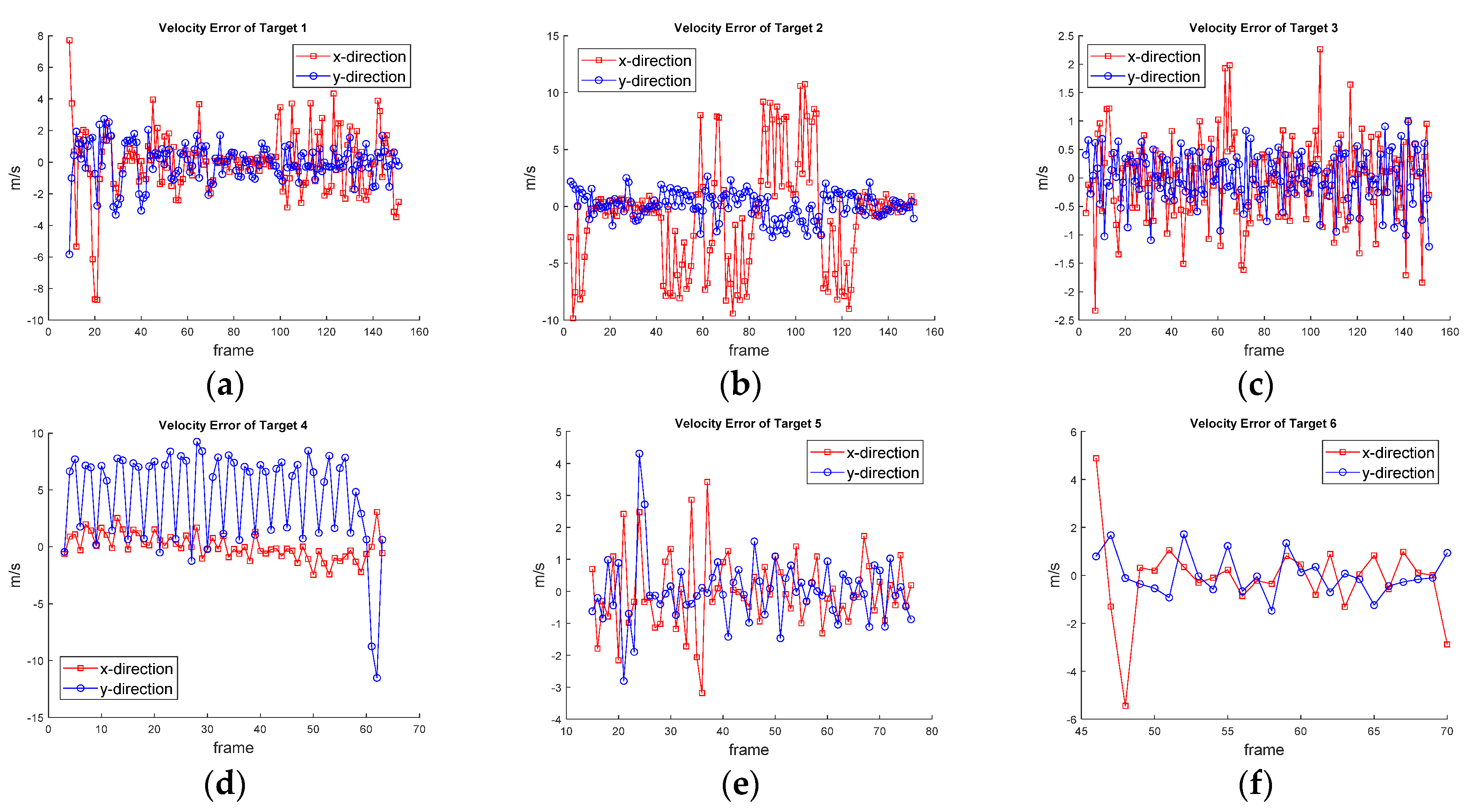
Figure 18 and Figure 19 show each target’s position and velocity errors. The position errors of Targets 2 and 4 are reduced drastically at the moment when the track association occurs as shown in Figure 18b,d. The number of track associations for Target 2 and 4 are 25 and 20, respectively, but only two associations occurred for Target 1.
Table 3 show the average position and velocity RMSE with and without track association, respectively. If there is more than one track for the target (Target 1, 2, 4), the longer track is considered to obtain the RMSEs. The average RMSE of position decreased from 2.56 m to 2.42 m, but the average RMSE of velocity increased from 2.20 m/s to 3.19 m/s.
Table 4 only considers the fused states of Targets 2 and 4. The second and fourth rows of the RMSE is counted for errors when track association occurs. Although the average RMSE of velocity increases from 1.11 m/s to 1.77 m/s, the position RMSE shows the accuracy improvement from 2.61 m to 0.67 m.

4.3.2. Tracking Results of Video 2

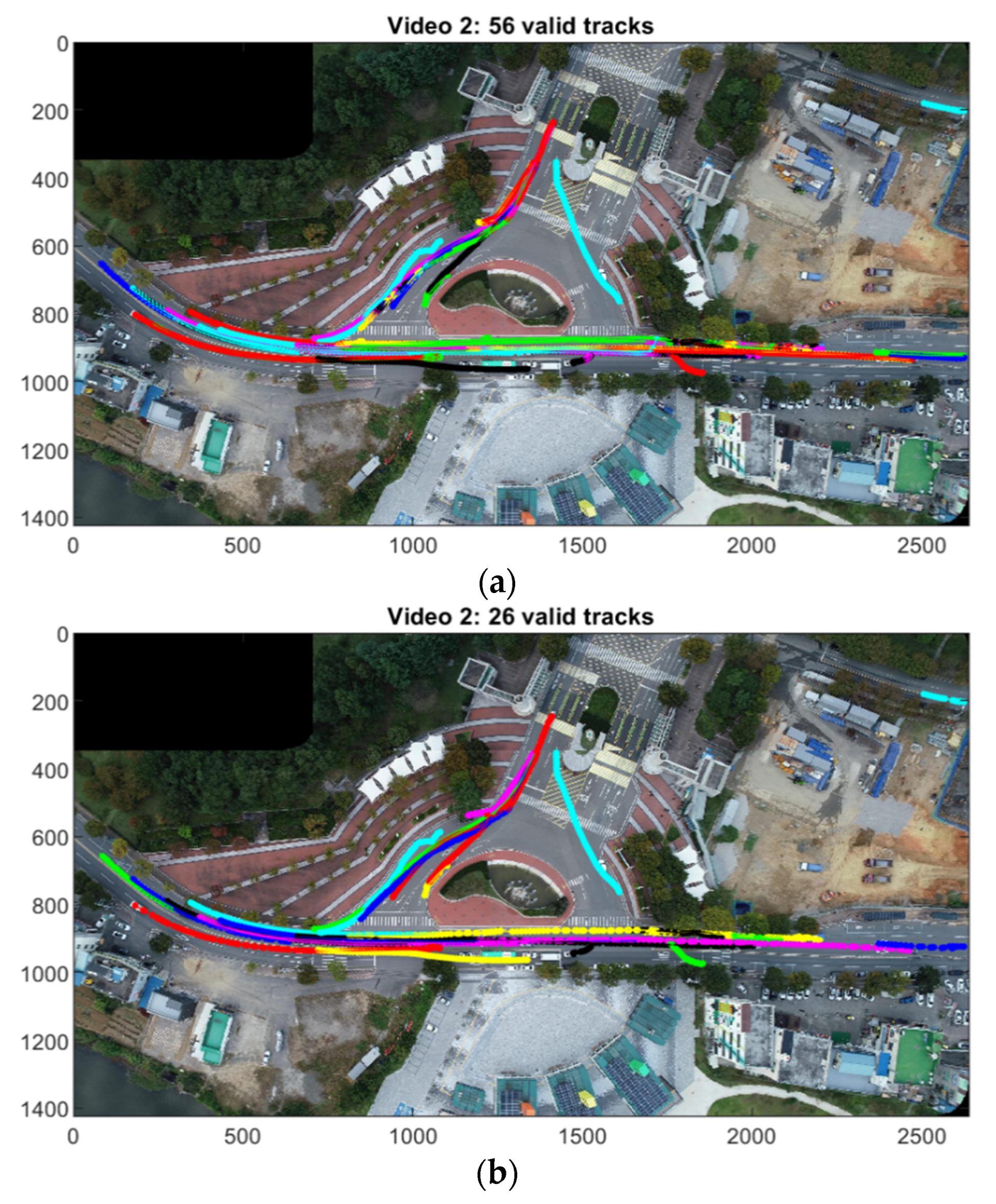
In Video 2, 23 targets appear for 214 frames. Many redundant tracks are caused by the multiple measurements on the same target without track association. A total of 56 valid tracks are reduced to 26 with the proposed method. The tracking efficiency increased from 41% to 92% because two segmented tracks were generated from one target. Figure 20a,b show the tracking results without and with track association, respectively, in the expanded frame. Two supplementary multimedia files (MP4 format) for tracking vehicles are available online. One is target tracking without track association (Supplementary Material Video S3) and the other is using the proposed method (Supplementary Material Video S4). The symbols and the numbers in the MP4 files are displayed the same way as in Video 1.
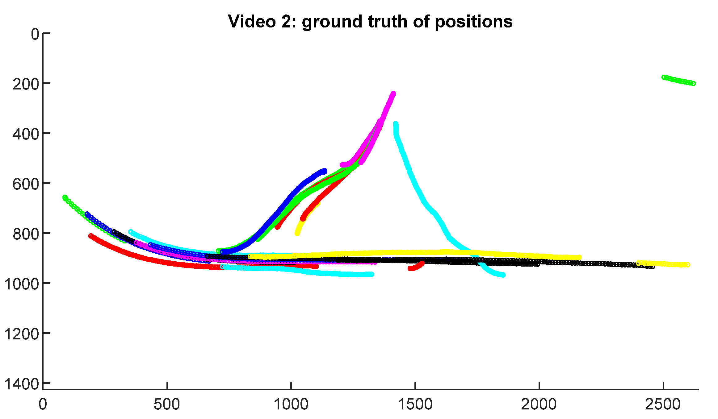
The ground truth of Video 2 is shown in Figure 21. Table 5 and Table 6 show the average position and velocity RMSEs without and with track association, respectively. The average position RMSE decreased from 1.64 to 1.21 m while the average velocity RMSE increased from 1.65 to 1.97 m/s.

5. Discussion

The detection rates of Video 1 and 2 are 92% and 89%, respectively. The detection rates were affected by simulating harsh conditions that the frames were gray-scaled and resized by 50%, and the frame rate was modified to 1/3 of the original one. Missing target detection degrades tracking performance; a long interval of missing targets may cause the track to be terminated or segmented. Using full color images at the original resolution and frame rate can increase the detection performance. A few false alarms are detected except for targets of no interest (pedestrians).
Typically, data association suffers from high clutters, low detection, state and measurement errors, and closely located targets. The NN is the most effective in computing and requires no initial assumptions on the number and states of targets. Indeed, the measurement characteristics in this study makes it possible to use the NN association as follows: (1) the target is transformed from the visual shape in the image frame into a point object in a Cartesian coordinate system during object detection, thus the measurement is not a continuous value, but a discrete 2D signal. The measurement resolution is the same with the spatial resolution of the image. Therefore, no false alarm or other targets can exist around the point of the true target depending on the physical shape of the target and the spatial resolution. In other words, as long as the validation region falls inside the target body, there is no possibility of the association with false alarms or other targets. In consequence, the accuracy of position estimates more matters than data association strategies. It is noted that the proposed track association scheme increases the accuracy of the target state in position as well as eliminating redundant tracks, (2) the false alarm rate is very low, and its existence is limited in space. Most false measurements were caused by buildings and some were caused by parked cars except for the non-target objects (pedestrians) in the experiments, so it is effective to use the NN association.
The NCV model is adopted in the experiments. The NCV, nearly constant acceleration (NCA), and coordinated turn (CT) models are most commonly used among various state-space dynamic models [35,36]. The choice of the model depends on the target’s maneuver, the measurement quality, and the measurement rate [36]. With high quality measurements, the NCA model can produce the accurate estimate of the acceleration. The CT model is often used for targets in horizontal planes and extended to 3D space [34]. We leave the investigation of the motion models in the various road environments such as highly curved roads in highway interchanges as well as straight roads in the future study.
In Video 1, Target 2 is moving horizontally, thus most of the errors are found in the x direction as shown in Figure 18b and Figure 19b. In Figure 18d and Figure 19d, the error of Target 4 is mostly found in the y direction because the target moves vertically. When the target states are fused, a more accurate position estimate is obtained although the velocity estimate becomes less accurate. Considering only the association states of the two targets, the position accuracy improved by 83.6%. In Video 2, a total of 23 various targets are considered and the drone changes a direction once, which expands the surveillance coverage in two dimensions. A total of 26 valid tracks are generated but two of them are segmented tracks for one target (bicycle), thus the tracking efficiency is 92%. Only one target (bus) was responsible for two additional tracks. Except for them, no redundant track was generated. The position accuracy increased by 26%. The experimental results show the proposed method is very effective in reducing redundant tracks and increasing the position accuracy.

6. Conclusions

In this paper, a moving drone has captured multiple moving vehicles. The coordinates of the frame were compensated for, and the moving objects were detected based on the frame subtraction. The targets were tracked with two-point initialization, a Kalman filter, and NN association. The track association scheme was proposed to merge redundant tracks and reduce the number of valid trajectories. The positioning accuracy was improved to show a higher accuracy of the fusion state.
The proposed tracking method is useful for stand-alone drone surveillance as well as multiple drones. A specific vehicle can be continuously locked and tracked in the large area by the drones’ hand-overing the target position. Thus, this system is suitable for vehicle chase as well as traffic control or counting vehicles. Multiple drones sharing a ground unit can improve target tracking accuracy, which remains for future study.

Supplementary Materials

The following are available online at https://www.mdpi.com/article/10.3390/app11094046/s1, Video S1: Previous Target Tracking of Video 1, Video S2: Proposed Target Tracking of Video 1, Video S3: Previous Target Tracking of Video 2, Video S4: Proposed Target Tracking of Video 2.

Author Contributions

Conceptualization, methodology, estimation, S.Y.; and registration, detection, D.-H.N. All authors have read and agreed to the published version of the manuscript.

Funding

This research was supported by Basic Science Research Program through the National Research Foundation of Korea (NRF) funded by the Ministry of Education (Grant Number: 2020R1I1A3A04037203).

Institutional Review Board Statement

Not applicable.

Informed Consent Statement

Not applicable.

Data Availability Statement

Not applicable.

Conflicts of Interest

The authors declare no conflict of interest.

References

  1. Alzahrani, B.; Oubbati, O.S.; Barnawi, A.; Atiquzzaman, M.; Alghazzawi, D. UAV assistance paradigm: State-of-the-art in applications and challenges. J. Netw. Comput. Appl. 2020, 166, 102706. [Google Scholar] [CrossRef]
  2. Zaheer, Z.; Usmani, A.; Khan, E.; Qadeer, M.A. Aerial surveillance system using UAV. In Proceedings of the 2016 Thirteenth International Conference on Wireless and Optical Communications Networks (WOCN), Hyderabad, India, 21–23 July 2016; pp. 1–7. [Google Scholar]
  3. Theys, B.; Schutter, J.D. Forward flight tests of a quadcopter unmanned aerial vehicle with various spherical body di-ameters. Int. J. Micro Air Veh. 2020, 12, 1–8. [Google Scholar]
  4. Zitová, B.; Flusser, J. Image registration methods: A survey. Image Vision. Comput. 2003, 21, 977–1000. [Google Scholar] [CrossRef] [Green Version]
  5. Tico, M.; Pulli, K. Robust image registration for multi-frame mobile applications. In Proceedings of the 2010 Conference Record of the Forty Fourth Asilomar Conference on Signals, Systems and Computers, Pacific Grove, CA, USA, 7–10 November 2010; pp. 860–864. [Google Scholar]
  6. Uchiyama, H.; Takahashi, T.; Ide, I.; Murase, H. Frame Registration of In-Vehicle Normal Camera with Omni-Directional Camera for Self-Position Estimation. In Proceedings of the 2008 3rd International Conference on Innovative Computing Information and Control, Dalian, China, 18–20 June 2008; p. 7. [Google Scholar]
  7. Tzanidou, G.; Climent-Pérez, P.; Hummel, G.; Schmitt, M.; Stütz, P.; Monekosso, D.; Remagnino, P. Telemetry assisted frame recognition and background subtraction in low-altitude UAV videos. In Proceedings of the 12th IEEE International Conference on Advanced Video and Signal Based Surveillance, Karlsruhe, Germany, 25–28 August 2015; pp. 1–6. [Google Scholar]
  8. Nam, D.; Yeom, S. Moving Vehicle Detection and Drone Velocity Estimation with a Moving Drone. Int. J. Fuzzy Log. Intell. Syst. 2020, 20, 43–51. [Google Scholar] [CrossRef]
  9. Li, S.; Yeung, D.-Y. Visual object tracking for unmanned aerial vehicles: A benchmark and new motion models. In Proceedings of the Thirty-Frist AAAI conference on Artificial Intelligence (AAAI-17), San Francisco, CA, USA, 4–9 February 2017; pp. 4140–4146. [Google Scholar]
  10. Du, D.; Qi, Y.; Yu, H.; Yang, Y.; Duan, K.; Li, G.; Zhang, W.; Huang, Q.; Tian, Q. The Unmanned Aerial Vehicle Benchmark: Object Detection and Tracking. Lect. Notes Comput. Sci. 2018, 375–391. [Google Scholar] [CrossRef] [Green Version]
  11. Zhang, S.; Zhuo, L.; Zhang, H.; Li, J. Object Tracking in Unmanned Aerial Vehicle Videos via Multifeature Discrimination and Instance-Aware Attention Network. Remote Sens. 2020, 12, 2646. [Google Scholar] [CrossRef]
  12. Kouris, A.; Kyrkou, C.; Bouganis, C.-S. Informed Region Selection for Efficient UAV-Based Object Detectors: Altitude-Aware Vehicle Detection with Cycar Dataset; IEEE/RSJ IROS: Las Vegas, NV, USA, 2019. [Google Scholar]
  13. Kamate, S.; Yilmazer, N. Application of Object Detection and Tracking Techniques for Unmanned Aerial Vehicles. Procedia Comput. Sci. 2015, 61, 436–441. [Google Scholar] [CrossRef] [Green Version]
  14. Fang, P.; Lu, J.; Tian, Y.; Miao, Z. An Improved Object Tracking Method in UAV Videos. Procedia Eng. 2011, 15, 634–638. [Google Scholar] [CrossRef]
  15. He, Y.; Fu, C.; Lin, F.; Li, Y.; Lu, P. Toward Robust Visual Tracking for Unmanned Aerial Vehicle with Tri-Attentional Correlation Filters; IEEE/RSJ IROS: Las Vegas, NV, USA, 2020; pp. 1575–1582. [Google Scholar]
  16. Chen, P.; Dang, Y.; Liang, R.; Zhu, W.; He, X. Real-Time Object Tracking on a Drone with Multi-Inertial Sensing Data. IEEE Trans. Intell. Transp. Syst. 2018, 19, 131–139. [Google Scholar] [CrossRef]
  17. Bian, C.; Yang, Z.; Zhang, T.; Xiong, H. Pedestrian tracking from an unmanned aerial vehicle. In Proceedings of the 2016 IEEE 13th International Conference on Signal Processing (ICSP), Chengdu, China, 6–10 November 2016; IEEE: New York, NY, USA, 2016; pp. 1067–1071. [Google Scholar]
  18. Sinha, A.; Kirubarajan, T.; Bar-Shalom, Y. Autonomous Ground Target Tracking by Multiple Cooperative UAVs. In Proceedings of the IEEE 2005 IEEE Aerospace Conference, Big Sky, MT, USA, 5–12 March 2005; IEEE: New York, NY, USA, 2005; pp. 1–9. [Google Scholar]
  19. Guido, G.; Gallelli, V.; Rogano, D.; Vitale, A. Evaluating the accuracy of vehicle tracking data obtained from Unmanned Aerial Vehicles. Int. J. Transp. Sci. Technol. 2016, 5, 136–151. [Google Scholar] [CrossRef]
  20. Rajasekaran, R.K.; Ahmed, N.; Frew, E. Bayesian Fusion of Unlabeled Vision and RF Data for Aerial Tracking of Ground Targets; IEEE/RSJ IROS: Las Vegas, NV, USA, 2020; pp. 1629–1636. [Google Scholar]
  21. Bar-Shalom, Y.; Li, X.R. Multitarget-Multisensor Tracking: Principles and Techniques; YBS Publishing: Storrs, CT, USA, 1995. [Google Scholar]
  22. Stone, L.D.; Streit, R.L.; Corwin, T.L.; Bell, K.L. Bayesian Multiple Target Tracking, 2nd ed.; Artech House: Boston, MA, USA, 2014. [Google Scholar]
  23. Blom, H.A.P.; Bar-shalom, Y. The interacting multiple model algorithm for systems with Markovian switching coeffi-cients. IEEE Trans. Autom. Control 1988, 33, 780–783. [Google Scholar] [CrossRef]
  24. Yeom, S.-W.; Kirubarajan, T.; Bar-Shalom, Y. Track segment association, fine-step IMM and initialization with doppler for improved track performance. IEEE Trans. Aerosp. Electron. Syst. 2004, 40, 293–309. [Google Scholar] [CrossRef]
  25. Lee, M.-H.; Yeom, S. Detection and Tracking of Multiple Moving Vehicles with a UAV. Int. J. Fuzzy Log. Intell. Syst. 2018, 18, 182–189. [Google Scholar] [CrossRef] [Green Version]
  26. Lee, M.-H.; Yeom, S. Multiple target detection and tracking on urban roads with a drone. J. Intell. Fuzzy Syst. 2018, 35, 6071–6078. [Google Scholar] [CrossRef]
  27. Yeom, S.; Cho, I.-J. Detection and Tracking of Moving Pedestrians with a Small Unmanned Aerial Vehicle. Appl. Sci. 2019, 9, 3359. [Google Scholar] [CrossRef] [Green Version]
  28. Yeom, S. Efficient multi-target tracking with sub-event IMM-JPDA and one-point prime initialization. LNEE 2009, 35, 127. [Google Scholar]
  29. Reid, D. An algorithm for tracking multiple targets. IEEE Trans. Autom. Control 1979, 24, 843–854. [Google Scholar] [CrossRef]
  30. Streit, R.L. Maximum likelihood method for probabilistic multi-hypothesis tracking. In Proceedings of the SPIE Aerosense Symposium Conference on Signal and Data processing of Small Targets, Orland, FL, USA, 5–7 April 1994; pp. 394–405. [Google Scholar]
  31. Vo, B.-N.; Ma, W.-K. The Gaussian Mixture Probability Hypothesis Density Filter. IEEE Trans. Signal Process. 2006, 54, 4091–4104. [Google Scholar] [CrossRef]
  32. Deb, S.; Yeddanapudi, M.; Pattipati, K.R.; Bar-Shalom, Y. A generalized S-D assignment algorithm for multisen-sor-multitarget state estimation. IEEE Trans. Aerosp. Electron. Syst. 1997, 33, 523–538. [Google Scholar]
  33. Tian, X.; Bar-Shalom, Y. Track-to-track fusion configurations and applications in a sliding window. J. Adv. Inf. Fusion 2009, 4, 146–164. [Google Scholar]
  34. Bar-Shalom, Y.; Willet, P.K.; Tian, X. Track and Data Fusion. In A Handbook of Algorithms; YBS Publishing: Storrs, CT, USA, 2011. [Google Scholar]
  35. Li, X.R.; Jilkov, V.P. Survey of maneuvering target tracking, part I: Dynamic models. IEEE Trans. Aerosp. Electron. Syst. 2003, 39, 1333–1364. [Google Scholar]
  36. Moore, J.R.; Blair, W.D. Multitarget-Multisensor Tracking: Applications and Advances; Bar-Shalom, Y., Blair, W.D., Eds.; Practical Aspects of Multisensor Tracking, Chap. 1; Artech House: Boston, MA, USA, 2000; Volume III. [Google Scholar]
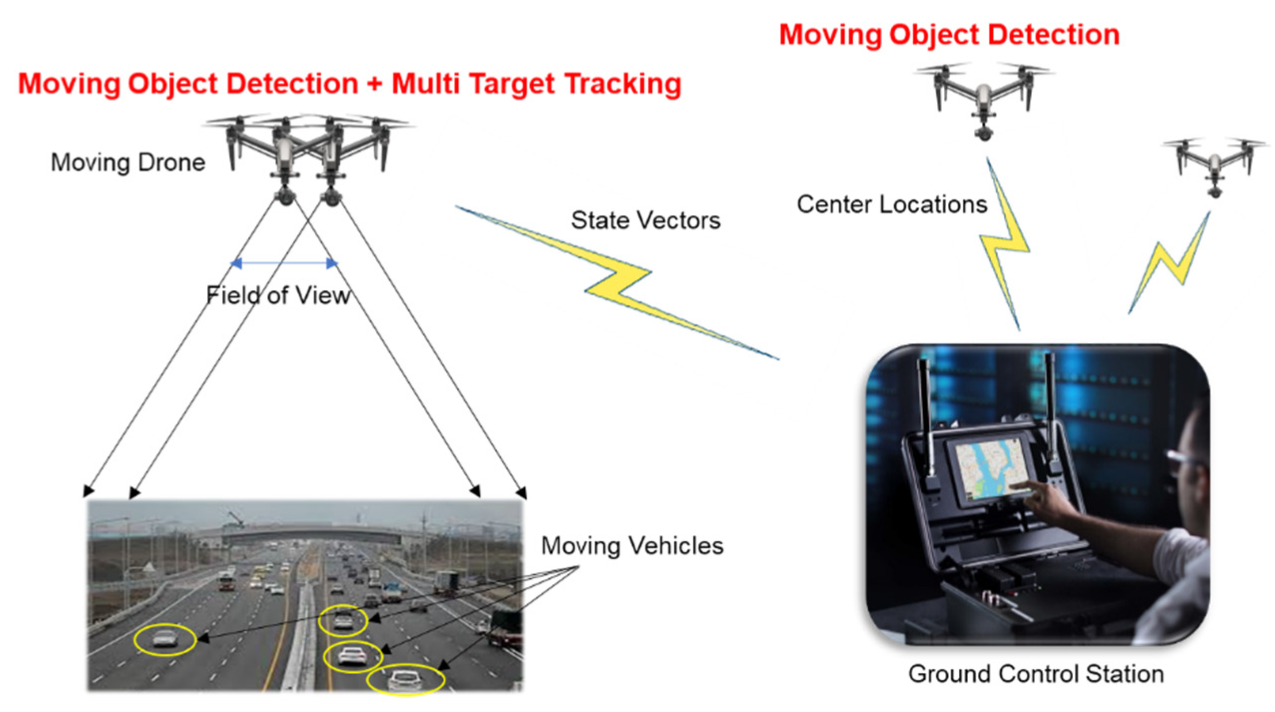
Figure 1. Illustration of the surveillance system by small drones.
Applsci 11 04046 g001
Figure 2. Block diagram of moving object detection and multiple target tracking.
Applsci 11 04046 g002
Figure 3. Block diagram of multiple target tracking.
Applsci 11 04046 g003
Figure 4. Illustration of the track association process, (a) two tracks s and t; (b) track association hypothesis testing; (c) track selection and fusion.
Applsci 11 04046 g004
Figure 5. Illustration of track life and track termination criteria.
Applsci 11 04046 g005
Figure 6. Video 1, (a) Targets 1–6 at the 54th frame; (b) Targets 7–9 at the 131st frame.
Applsci 11 04046 g006
Figure 7. Video 2, (a) Targets 1–10 at the 7th frame; (b) Targets 11–17 at the 117th frame; (c) Targets 18–23 at the 218th frame.
Applsci 11 04046 g007
Figure 8. Video 1: moving object detection of Figure 6b, (a) frame registration and subtraction; (b) morphological filtering; (c) removing false alarms; (d) detection results (bounding boxes).
Applsci 11 04046 g008
Figure 9. Video 2: moving object detection of Figure 7b, (a) frame registration and subtraction; (b) morphological filtering; (c) removing false alarms; (d) detection results (bounding boxes).
Applsci 11 04046 g009
Figure 10. Video 1: 709 detections in the expanded frame.
Applsci 11 04046 g010
Figure 11. Video 2: 1016 detections in the expanded frame.
Applsci 11 04046 g011
Figure 12. Video 1, (a) 13 valid tracks without track association; (b) 10 valid tracks with the proposed method.
Applsci 11 04046 g012
Figure 13. Tracking results of Target 1, (a) without track association; (b) with the proposed method.
Applsci 11 04046 g013
Figure 14. Tracking results of Target 2, (a) without track association; (b) with the proposed method.
Applsci 11 04046 g014
Figure 15. Tracking results of Target 4, (a) without track association; (b) with the proposed method.
Applsci 11 04046 g015
Figure 16. Tracking results of Target 7.
Applsci 11 04046 g016
Figure 17. Ground truths of Video 1.
Applsci 11 04046 g017
Figure 18. Position RMSE of (a) Target 1; (b) Target 2; (c) Target 3; (d) Target 4; (e) Target 5; (f) Target 6; (g) Target 7; (h) Target 8; (i) Target 9.
Applsci 11 04046 g018
Figure 19. Velocity RMSE of (a) Target 1; (b) Target 2; (c) Target 3; (d) Target 4; (e) Target 5; (f) Target 6; (g) Target 7; (h) Target 8; (i) Target 9.
Applsci 11 04046 g019aApplsci 11 04046 g019b
Figure 20. Video 2, (a) 56 valid tracks without track association; (b) 26 valid tracks with the proposed method.
Applsci 11 04046 g020
Figure 21. Ground truths of Video 2.
Applsci 11 04046 g021
Table 1. Video descriptions.
Video 1Video 2
Multicopter/CameraPhantom 4/BundleInspire 2/Zenmuse X5
Flying speed (m/s)5.15
Flying time (sec)1524
Flying directionWest→EastWest→East→North
Actual fame number151241
Actual frame size (pixels)2048 × 10801920 × 1080
Actual frame rate (fps)10
Number of moving vehicles923
Table 2. Parameter design.
Video 1Video 2
Vmax (m/s) for speed gating30
σ x = σ y (m/s2)3010
r x = r y (m/s)0.5 1.5
γ g for measurent association810
γ f for track association17070
Valid track criteria
(Minimum track life)
9
Track terminaion criteria
(Maximum searching number)
15
Table 3. Position and velocity RMSE of Video 1.
Target 1Target 2Target 3Target 4Target 5Target 6Target 7Target 8Target 9Avg.
Position
(m)
Previous6.012.880.622.340.582.346.290.841.132.56
Proposed5.892.411.642.42
Velocity
(m/s)
Previous2.321.060.861.151.561.894.611.954.412.20
Proposed2.454.826.123.19
Table 4. Position and velocity RMSE of Fused States.
Target 2Target 4Avg.
Position
(m)
Previous2.882.342.61
Fused State only0.850.490.67
Velocity
(m/s)
Previous1.061.151.11
Fused State only2.331.211.77
Table 5. Position RMSE of Video 2 (m).
Target 1Target 2Target 3Target 4Target 5Target 6Target 7Target 8Target 9Target 10Target 11Target 12
Previous2.402.611.942.310.601.531.651.080.270.341.420.26
Proposed1.412.550.840.470.660.310.66
Target 13Target 14Target 15Target 16Target 17Target 18Target 19Target 20Target 21Target 22Target 23Avg.
Previous1.552.730.211.923.042.941.610.964.011.290.991.64
Proposed0.732.80.391.831.040.481.820.870.761.21
Table 6. Velocity RMSE of Video 2 (m/s).
Target 1Target 2Target 3Target 4Target 5Target 6Target 7Target 8Target 9Target 10Target 11Target 12
Previous0.951.271.360.891.852.395.971.051.120.951.890.81
Proposed1.951.321.651.682.310.911.76
Target 13Target 14Target 15Target 16Target 17Target 18Target 19Target 20Target 21Target 22Target 23Avg.
Previous1.182.661.101.151.491.140.990.891.121.544.281.65
Proposed2.174.031.301.312.291.433.101.744.151.97
Publisher’s Note: MDPI stays neutral with regard to jurisdictional claims in published maps and institutional affiliations.