Article

Development of a Wearable Finger Exoskeleton for Rehabilitation

by
Carlos Hernández-Santos
1,*,
Yasser A. Davizón
2,
Alejandro R. Said
3,
Rogelio Soto
3,
L.C. Félix-Herrán
4 and
Adriana Vargas-Martínez
3
1
Tecnológico Nacional de México/IT de Nuevo León, México, Av. Eloy Cavazos 2001, Guadalupe 66170, Nuevo León, Mexico
2
Universidad Politécnica del Mar y la Sierra, Potrerillos del Norte, Tayoltita 82740, Sinaloa, Mexico
3
Tecnologico de Monterrey, Escuela de Ingeniería y Ciencias, Campus Monterrey, Eugenio Garza Sada 2501, Monterrey 64849, Nuevo León, Mexico
4
Tecnologico de Monterrey, School of Engineering and Sciences, Blvd. Enrique Mazón López 965, Hermosillo 83000, Sonora, Mexico
*
Author to whom correspondence should be addressed.
Appl. Sci. 2021, 11(9), 4145; https://doi.org/10.3390/app11094145
Submission received: 8 March 2021 / Revised: 13 April 2021 / Accepted: 13 April 2021 / Published: 1 May 2021
(This article belongs to the Special Issue Advances in Technological Rehabilitation)

Abstract

:
This research work shows a new architecture of a novel wearable finger exoskeleton for rehabilitation; the proposed design consists of a one degree of freedom mechanism that generates the flexion and extension movement for the proximal, medial and distal phalange of the fingers to assist patients during the rehabilitation process, after neurological trauma, such as a stroke. The anatomy and anthropometric measures for the hand were used to define the design of the mechanism. In the analytic part, the representative equations for the forward and inverse kinematic analysis of the fingers are obtained, also a dynamic analysis is presented. The position and displacement continued for the structural analysis, were developed by following a static analysis, to know the deformation that the structure links show when an external load is applied in the mechanism. As result, a prototype was manufactured with acrylonitrile butadiene styrene (ABS) using an additive manufacturing machine.

1. Introduction

Nowadays, due to technological advances, robotics are present in different places, such as hospitals, factories, schools, and houses [1]. One of the areas where robotics has a large presence is in healthcare, where its applications are focused on rehabilitation, helping people with disease or disability to perform daily activities, or provide therapies to improve physical or cognitive functions [1].
There are several diseases, which affect physical functions of the human hand, generating limitations in performing activities like grasping objects or opening a tin or a bottle of water. Many robotic systems specifically intended for hand rehabilitation have been reported in the literature, where two different hand exoskeleton systems exist: single-phalanx devices, in which the robot exerts forces to the hand only at the fingertips, and multi-phalanx ones, where the device can directly control each phalanx of the hand.
The single-phalanx solution has a rigid mechanism and a cable-driven architecture; there are a few examples found in the literature and most of them use actuation systems separated by the device (usually the device is located on the hand and the motors are placed on the ground) [2,3]. Only a narrow part of these examples directly use motors placed on the back of the hand (extraordinary portability but limited in terms of device performance due to the weight and high cost). An example of such a system is WaveFlex, which is a commercial continuous passive movement device for physical therapy of the hand. An electric motor is used for actuation [4]. To reduce the load and the weight, in [5], a device is proposed based on linear electric actuators with a mechanism with two DOF for each finger which allows a maximum force of 10 N, a reduced vertical load (maximum 6 cm with respect to the back of the hand) and a weight of 0.5 kg for the whole device. Lambercy et al. [6] created a thumb exoskeleton for the main purpose of rehabilitation of lost thumb functions and to add thumb opposition to the therapy process. The exoskeleton allows flexion/extension and abduction/adduction to work in combination to achieve circular cone-shaped opposition using a single active linear actuator and passive joints to transmit the motion through a four-bar linkage (redundant) mechanism. Additionally, the spread of soft-robotic applications has led to some preliminary examples of human exoskeleton systems based on elastomeric materials or fluid structures [7,8]. The Hand Spring Operated Movement Enhancer (HandSOME) uses elastic cords as springs to assist with finger and thumb extension and provides an assistance profile that emulates torque versus extension angle profiles for passive movement [9]. Gloreha-Hand Robotic Rehabilitation is a wearable glove for the human hand. The glove is composed of one pneumatic actuator located on the upper side of the forearm and several elastic transmissions, which are moved by the actuator to properly transmit displacements, speed, and forces to one or more impaired fingers during a rehabilitation session [10].
As regards actuation systems, cable-driven solutions are widely employed for their implicit simplicity [11,12,13], while rigid actuator architectures (based on linear actuators or hydraulic ones) may have problems due to the associated weights and encumbrances [14,15]. An interesting solution is described in [16], where the authors developed a HEXOSYS with a four-DOF mechanism (one actuated and three passive) for the finger that can apply a continuous force of 45 N with a total weight of 1 kg. The drawback of this solution is the high vertical load and the impossibility of applying this mechanism to all four fingers. Nevertheless, current solutions for single-DOF mechanisms are mainly related to assisting grasping gestures but with very simplified kinematics [17].
Concerning mechanisms, multi-phalanx or multi-degree-of-freedom (DOF) kinematic chains have been proposed [18,19,20,21,22,23]. Kazerooni [24] describes an exoskeleton based on a three-DOF mechanism, with three electric motors, which are very powerful (flexo-extension with 5 N maximum force) and precise, but are very heavy and bulky (0.5 kg and maximum height concerning the back of the hand of 8 cm for a one-finger mechanism). IOTA [25] is two-degree-of-freedom (DOF) thumb exoskeleton that can actuate carpometacarpal (CMC) and metacarpophalangeal (MCP) joints through motion ranges required for daily activities; the actuators for the CMC and MCP joints are located off-board of the orthotic device, inside a control box. Actuation of the joints is achieved by two servos and two spring-return cable transmissions connected between the servos and the orthotic device. Pneumatic Muscle-Torsion Spring (PM-TS) for finger therapy, is a wearable robotic hand for assisted repetition, which uses a pneumatic muscle actuator structure and a torsion spring (TS) and has two DOF for the driven fingers, which makes the movement of fingers more suitable and flexible [26]. Robotic system-to-hand rehabilitation [27], uses an exoskeleton with two DOF for finger rehabilitation of problems of motion caused by cerebrovascular event. ExoGlove [28] is a soft wearable exoskeleton that comprises an embedded glove with pneumatic actuators of variable stiffnesses for hand assistance and rehabilitation applications. The Assistive Rehabilitation Robotic Glove [29] consists of two novel designs for robotic glove rehabilitation using an exoskeleton to provide actuation for flexion, thereby limiting the number of active actuators required. HX [30] is an exoskeleton that has been designed to maximize comfort, wearability, and user safety, exploiting chains with multiple degrees-of-freedom with a modular architecture. ExoHand [31] is an exoskeleton from Festo that can be worn like a glove. The fingers can be actively moved and their strength amplified; the operator’s hand movements are registered and transmitted to the robotic hand in real-time. The five-fingered haptic glove design [32] is a mechanism with a light weight and a portable actuator system that fits on the hand. ATX [33] is an exoskeleton created to facilitate research in hand rehabilitation therapy. The actuated finger exoskeleton [20] provides independent control of all three joints of the index finger. HEXORR [17] is a device that provides a full range of motion (ROM) for all of the hand’s digits. A hand exoskeleton system for index finger rehabilitation [34] uses both active and passive rehabilitative motions. Finally, the novel exoskeleton robotic system for hand rehabilitation [35] is a novel hand exoskeleton rehabilitation device that facilitates tendon therapy exercises.
Table 1 presents a comparative review of exoskeletons developed for hand rehabilitation. Not all of the exoskeletons can be applied effectively to daily life, e.g., only a few can be used alone without a large drive device. Some are too complex, bulky, and unwearable, with many active DOF, or are too expensive for home and personal use.
By following this approach, inspired by extreme portability and affordability, this work presents a new finger mechanism based on linkage approximation, using only one active degree of freedom per finger to obtain full actuation and it was assembled using a 3D printing machine from a thermoplastic polymer, acrylonitrile butadiene styrene (ABS); the structure of the proposed exoskeleton presented in this paper is based on human hand capabilities, with the ranks of motion and physical length as important criteria.
This paper is organized as follows: In Section 2, the design of the finger exoskeleton is presented. Section 3 develops the kinematics and dynamics for the proposed exoskeleton with one DOF. Section 4 presents experimental results for the exoskeleton kinematics and dynamics, followed by proper structural analysis. Section 5 presents the discussion on the proposed exoskeleton and, finally, in Section 6, some important conclusions and suggestions for future research are presented.

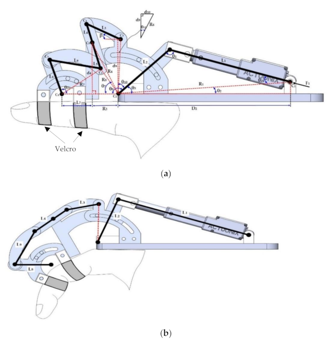
2. Structure Design for the Finger Exoskeleton

The proposed material design consists of a one-DOF mechanism that allows the flexion and extension of finger movements of the hand; it is made up of different links that adhere to the proximal phalanx and the middle phalanx of fingers L1 and L2, respectively, see Figure 1. According to the configuration of the links, the mechanism transforms linear movement from the actuator into a rotational type, allowing the movement of finger joints, which are represented as θ1, θ2, and θ3. The forces resulting from these movements are called F1 and F2.
These forces are present on the first two phalanges of the fingers (proximal phalanx and middle phalanx), which in turn generate rotational movements of the metacarpophalangeal (MCP), proximal interphalangeal (PIP), and distal interphalangeal (DIP) joints. It is important to note that the distal phalanx has a sub-acted movement with respect to the middle phalanx, so it moves in coordination with it. For this reason, the proposed mechanism only applies rotational movements on the proximal phalanx and the middle phalanx. The sub-acted finger movements mentioned above are also contemplated for the subsequent studies carried out in the present investigation.

2.1. Mechanical Design

The proposed design was developed in SolidWorks, and is shown in Figure 2a, where is possible to see the isometric exoskeleton. The proposed exoskeleton is formed by four parts, where part 1 is the exoskeleton base, part 2 is the selected linear actuator (Actuonix model L12-50-100 [37]), the main function of the actuator is to transmit linear-type movements towards the mechanisms that move the proximal phalanges and the middle phalanges. Part 3 is the mechanism that transmits the movement of the actuator towards the proximal phalanx and, finally, part 4, is the mechanism that transmits the movement of the actuator towards the middle phalanx and the distal phalanx through the same sub-acted movement.
The motion transmission is based on a linkage mechanism that allows the possibility of coupling the motion of phalanxes so that natural hand movements are achievable using only one active DOF driven using one linear actuator per finger. Additionally, bars can transmit both tensile and compressive loads, so the same mechanism can perform extension and flexion movement of the fingers. Each phalange element is attached to the human phalange using Velcro straps.
As shown in Figure 2b, the mechanism is formed as a base mechanism (element 1), the linear actuator is used to transmits the force to mechanisms (elements 2 and 3). The pushing force allows the flexion movement, and the pulling force allows the extension movement. The proximal phalanx movement is generated by elements 4 and 5, and elements 6, 7, and 8 generate a rotational movement for the mechanism that moves the middle phalanx. The movement of the distal phalanx is generated through the mechanism that moves the middle phalanx since these two have a sub-acted motion with respect to each other.

2.2. Design Parameters

The finger parameters for the development of the proposed design are shown in Table 2 [38]. Each finger on the hand has different lengths as do the phalanges that compose them. However, due to design issues, and as a starting point for this research, the mechanisms used for each finger’s movement have the same dimensions, starting from the lengths of the phalanges of the middle finger. The proposed ranges of motion were taken from the range of each of the finger phalange’s natural motion.

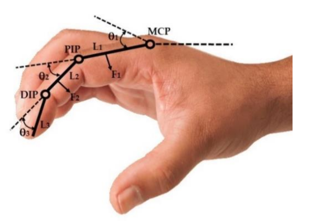
3. Exoskeleton Hand Analysis

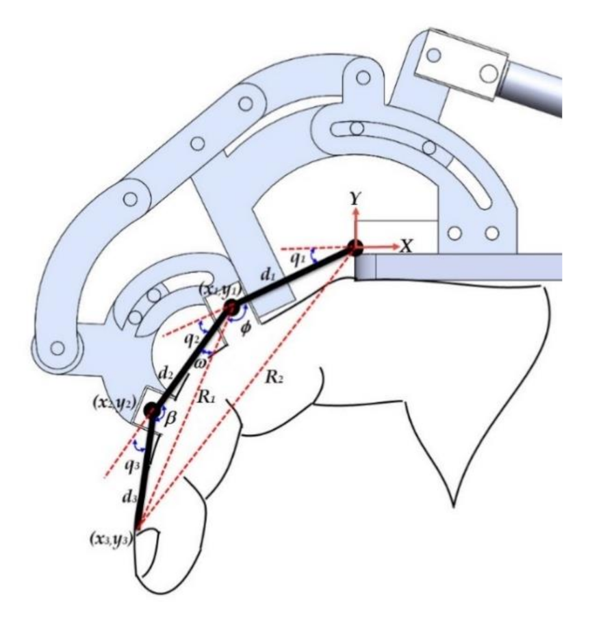
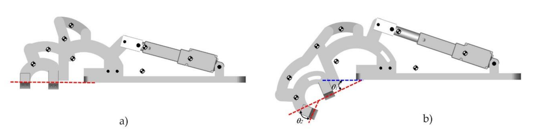
3.1. Position Analysis

In several mechanisms, position analysis has the goal to determine the position of all the links in different phases of an operative cycle [39].
The position analysis of exoskeleton components is developed using an analytic method through a geometric approach. In Figure 3a, a schematic diagram is shown, where the lengths of the exoskeleton links are known. L1 represents the element that joins the linear actuator with element L2. The length of L1 is variable according to the linear displacement of the actuator; L2 represents the section of the mechanism that moves the proximal phalanx; L3 is the element that allows the angular displacement of link L4L5; L4L5 is the element that moves to link L8; L9 is the element linked to link L4L5 with link L8; L8 represents the section of the mechanism that moves the middle phalanx; F1 is the force applied by the linear actuator to move the mechanism. Figure 3b, represents the final position achieved after the linear actuator reaches its final position.
To solve for θ2, from Figure 3a, the initial position of element L2 is obtained, using the values of L2, L1, D2, and d1 the input data are:
R 1 = d 1 2 D 2 2
sin θ 2 = d 1 R 1
c o s θ 2 = 1 sin θ 2 2
θ 2 = a t a n 2 d 1 d 1 2 + D 2 2 , 1 d 1 2 d 1 2 + D 2 2
where atan2 is the inverse tangent function. The atan2 function is different from the conventional arctangent function. The major difference is that the atan2 function also determines the quadrant of an angle, which is not the case for the arctangent function.
In the same way, using L2 and R1 gets initial the position for θ1i
θ 1 i = a t a n 2 1 R 1 2 + L 2 2 L 1 i 2 2 R 1 L 2 2 , R 1 2 + L 2 2 L 1 i 2 2 R 1 L 2
θ 3 i = θ 1 i + θ 2
where L1i and θ3i represent the initial position for the linear actuator and link L1, respectively.
The final position for the same elements, when the linear actuator has its maximum length, can be obtained as:
θ 1 f = a t a n 2 1 R 1 2 + L 2 2 L 1 f 2 2 R 1 L 2 2 , R 1 2 + L 2 2 L 1 f 2 2 R 1 L 2
θ 3 f = θ 1 f + θ 2
θ 3 T = θ 3 f θ 31
where i and f represent the initial and final positions, and θ3T is the angular position for link L2.
Using L1, L2, and R1 the θ24 equation can be obtained as:
θ 24 = a t a n 2 1 R 1 2 + L 1 f 2 L 2 2 2 R 1 L 1 f 2 , R 1 2 + L 1 f 2 L 2 2 2 R 1 L 1 f
and
θ 10 = 90 θ 3 f
Using L2 and θ3, the distance between centers of rotation are C5 and C2. Angular displacement β of element L3 is expressed by:
θ 7 = a t a n 2 d 4 , R 3
R 4 = R 3 2 + d 4 2
R 6 = d 9 2 + d 10 2
θ 12 = a t a n 2 d 10 R 6 , 1 d 10 R 6 2
θ 11 = θ 8 θ 7 θ 10 + θ 12
where θ11 is the angle between the center of rotation C2C3 and C3C5. Using the value of Equation (16), the value of R5 is expressed as:
R 5 = R 4 2 + R 6 2 2 R 4 R 6 cos θ 11
β = a t a n 2 1 L 4 2 + L 3 2 + R 5 2 2 R 5 L 3 2 , L 4 2 + L 3 2 + R 5 2 2 R 5 L 3 a t a n 2 1 R 4 cos θ 7 θ 3 T + d 10 R 5 2 , R 4 cos θ 7 θ 3 T + d 10 R 5
where Equation (16) describes the angular displacement of element L3. Using R5, L3 and L4 the angular displacement for the link L3 and L4 can be obtained as:
θ 21 = a t a n 2 1 L 3 2 + R 5 2 + L 4 2 2 R 5 L 4 2 , L 3 2 + R 5 2 + L 4 2 2 R 5 L 4
where θ21 is the angle between segments C2C3 and C3C5. Using the triangle formed by elements R8, d4, and L5, the angular position for links L8 and L9 can be expressed by:
R 7 = L 7 2 + R 8 2 2 L 7 R 8 cos 90 θ 18
R 8 = L 5 2 + d 4 2 2 L 5 d 4 cos 180 θ 14 θ 16 θ 17
θ 19 = a t a n 2 1 R 8 2 + R 7 2 + L 7 2 2 R 7 L 7 2 , R 8 2 + R 7 2 + L 7 2 2 R 7 L 7
θ 20 = a t a n 2 1 L 9 2 + L 8 2 + R 7 2 2 R 7 L 8 2 , L 9 2 + L 8 2 + R 7 2 2 R 7 L 8
θ 22 = θ 19 + θ 20

3.2. Inverse Kinematics

This section is concerned with finding the solution to the inverse kinematics problem, which consists in determining the joint variables in terms of the end-effector position and orientation. It is commonly known from the literature, that, for open kinematic chains, the determination of closed-form equations for inverse kinematics represents a greater challenge than the forward kinematics [1].
Figure 4 shows a simplified sketch in the XY plane, where the base coordinate is at the center of the proximal phalange joint. The local frames (Xi, Yi) are assigned to each joint, di denotes the length of link i, qi is the articular angle, ω represents the angle between medial phalange and R1 and β represent the angles between the medial and distal phalanges.
The approach followed in this paper for finding the inverse kinematics solution of the exoskeleton consists in determining joints angles q1, q2, and q3 given the global position distal phalange.
Using Figure 4, results in
q 1 = atan 2 y 1 d 1 , 1 y 1 d 1 2
q 2 = 180 ϕ ω
q 3 = 180 β
where, applying the cosines law to the triangle bounded by d2 and d3, the solution for β is expressed by:
ϕ = atan 2 1 d 1 2 + R 1 2 R 2 2 2 R 1 d 1 2 , d 1 2 + R 1 2 R 2 2 2 R 1 d 1
ω = atan 2 1 d 2 2 + R 1 2 d 3 2 2 R 1 d 2 2 , d 2 2 + R 1 2 d 3 2 2 R 1 d 2
β = atan 2 1 d 3 2 R 1 2 + d 2 2 2 d 3 d 2 2 , d 3 2 R 1 2 + d 2 2 2 d 3 d 2

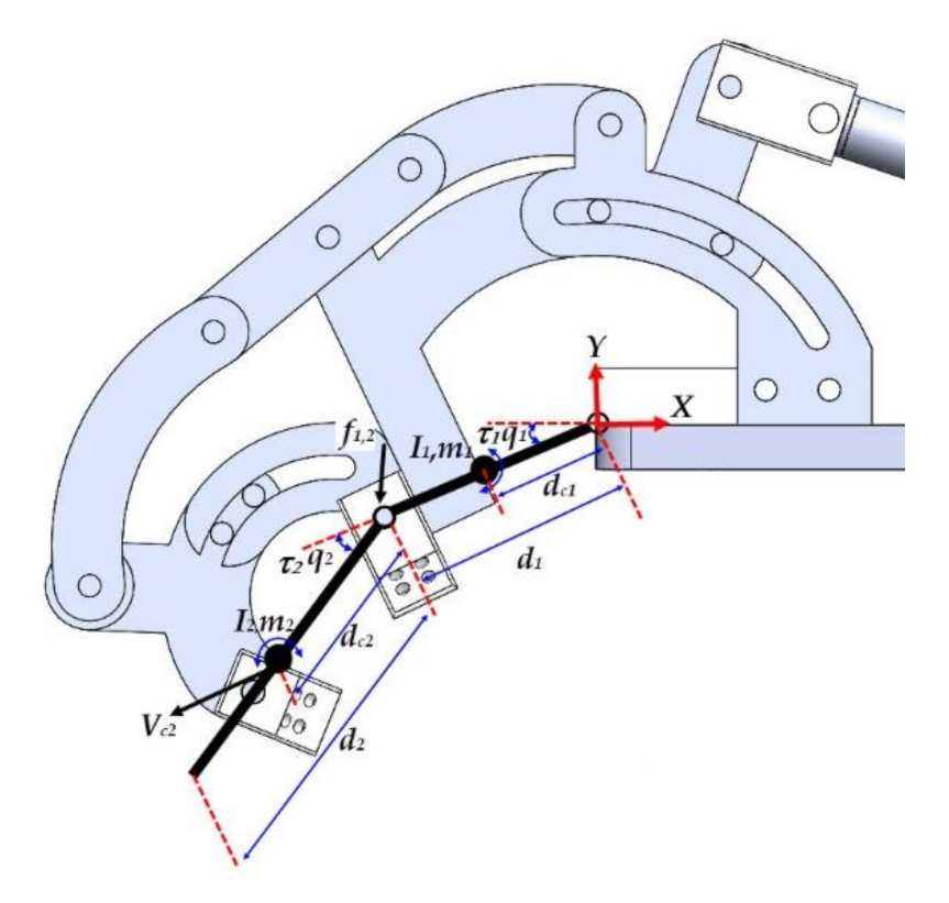
3.3. Dynamics Analysis

The approach followed in this paper applies the Newton–Euler dynamic formulation to solve the dynamics of the exoskeleton hand. The main advantages of this technique are the facility of implementation and obtaining models with a reduced number of operations. The Newton–Euler formulation is derived by the direct interpretation of Newton’s second law of motion, which describes system dynamics in terms of force and momentum. The equations incorporate all the forces and momentum acting on individual exoskeleton links, including the coupling forces and momentum between the links. The equations obtained from the Newton–Euler method include the constraint forces acting between adjacent links. Thus, additional arithmetic operations are required to eliminate these terms and obtain explicit relations between the joint torques and the resultant motion in terms of joint displacements.
For the development of dynamic analysis through the Newton–Euler formulation, the finger exoskeleton mechanism is simplified and shown in Figure 5. The diagram represents only the links of the proximal phalanx and middle phalanx of the fingers; the main reason why only these two phalanxes are contemplated is because of the type of movement that the distal phalanx performs concerning the middle phalanx, which is an underactuated type, which, when exerting a force on the middle phalanx in the same way will generate movement in the distal phalanx.
d1 and d2 are the lengths of the section of the mechanism that moves the proximal phalanx and the middle phalanx; dc1 and dc2 are the lengths of each joint of the phalanges (MCF, IFP) with its center of mass; m1 and m2 are the masses of each section of the mechanism; q1 and q2 are the joint coordinates of the proximal phalanx and the middle phalanx, respectively, and I1 and I2 represent the inertia tensor for each link.
Using Figure 5, the Newton–Euler equations for the dynamic model for link d1 are:
f 0 , 1 - f 1 , 2 + m 1 g m 1 V ˙ c 1 = 0
N 0 , 1 - N 1 , 2 + r 1 , c 1 × f 1 , 2 r 0 , c 1 × f 0 , 1 I 1 ω ˙ 1 = 0
where fi−1,i, and −fi,i+1 are the coupling forces applied to link i by links i − 1 and i + 1. Note that all vectors are 2 × 1, so that moment Ni−1,i and the other vector products are scalar quantities. Similarly, for link d2:
f 1 , 2 + m 2 g m 2 V ˙ c 2 = 0
N 1 , 2 r 1 , c 2 × f 1 , 2 I 2 ω ˙ 2 = 0
where Vi represents the velocity of the centroid for each link, ωi represents the angular velocity for link i, ω ˙ i represents the angular acceleration for link i. To obtain a closed-form for dynamic equations, first, eliminate the constraint forces and separate them from the joint torques, to explicitly involve the joint torques in the dynamic equations. For Figure 5, joint torques τ1 and τ2 are equal to the coupling moments:
N i 1 , i = τ i , i = 1 , 2
Substituting Equations (34) and (35) into Equation (32) gets
τ 1 - τ 2 r 0 , c 1 × m 1 V ˙ c 1 r 0 , 1 × m 2 V ˙ c 2 + r 0 , c 1 × m 1 g + r 0 , 1 × m 2 g I 1 ω ˙ 1 = 0
τ 2 r 1 , c 2 × m 2 V ˙ c 2 + m 2 g I 2 ω ˙ 2 = 0
Rewriting Equations (36) and (37) in terms of qi and linear velocity Vci is
V c 1 = d c 1 q ˙ 1 sin q 1 d c 1 q ˙ 1 cos q 1
V c 2 = d 1 sin q 1 + d c 2 sin q 1 + q 2 q ˙ 1 d c 2 sin q 1 + q 2 q ˙ 2 d 1 cos q 1 + d c 2 cos q 1 + q 2 q ˙ 1 + d c 2 cos q 1 + q 2 q ˙ 2
Substituting Equations (38) and (39) into Equations (36) and (37), the closed-form dynamic equations are given by:
τ 1 = H 11 q ¨ 1 + H 12 q ¨ 2 h q ˙ 2 2 2 h q ˙ 1 q ˙ 2 + G 1
τ 2 = H 22 q ¨ 2 + H 21 q ¨ 1 + h q ˙ 1 2 + G 2
where
H 11 = m 1 d c 1 2 + I 1 + m 2 d 1 2 + d c 2 2 + 2 d 1 d c 2 cos q 2 + I 2
H 22 = m 2 d c 2 2 + I 2
H 12 = m 2 d c 2 2 + d 1 d c 2 cos q 2 + I 2
h = m 2 d 1 d c 2 sin q 2
G 1 = m 1 d c 1 g cosq 1 + m 2 g d c 2 cos q 1 + q 2 + d 1 cos q 1
G 2 = m 2 g d c 2 cos q 1 + q 2

4. Experiment Results

This work used MATLAB to produce numerical examples of the analytical solutions for the exoskeleton kinematics and dynamics. In addition to this, the paper uses SolidWorks and the SimMechanics toolboxes from MATLAB to model and simulate mechanical systems that use standard Newtonian laws.

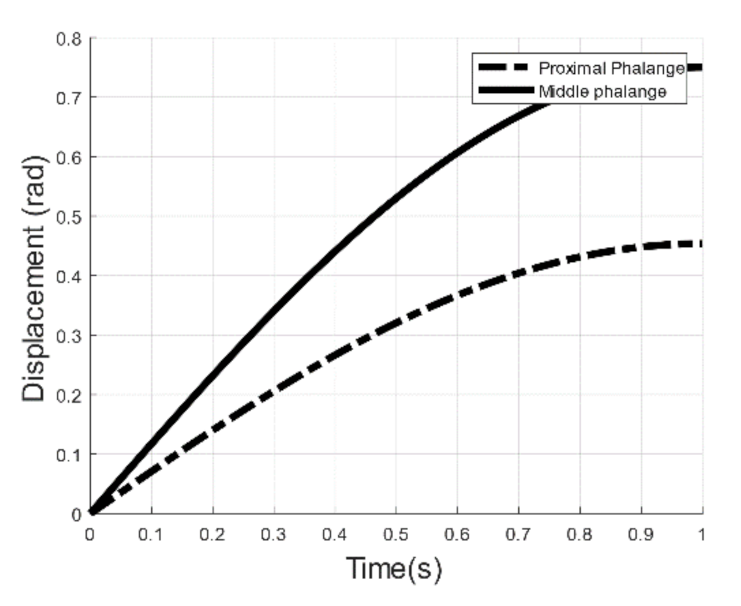
4.1. Position Analysis

In this simulation, the positions of the main links of the proposed mechanism with respect to the position of the driving link (linear actuator) were determined using the closed equations, Equations (1)–(24), developed in Section 3.1. With the help of these data, the range of the motion structure that moves to the proximal phalanx and the middle phalanx were determined, see Table 3.
Figure 6 presents the result of simulation in SimMechanics, which was carried out in a time horizon of 21 s. For the first 10 s of the simulation, the MCP joint generated a θ1 = 26° movement and PIP generated θ1 = 43°. After 11 s, the MCP and PIP joints returned to their initial position in a time window of 11–21 s.

4.2. Inverse Kinematics
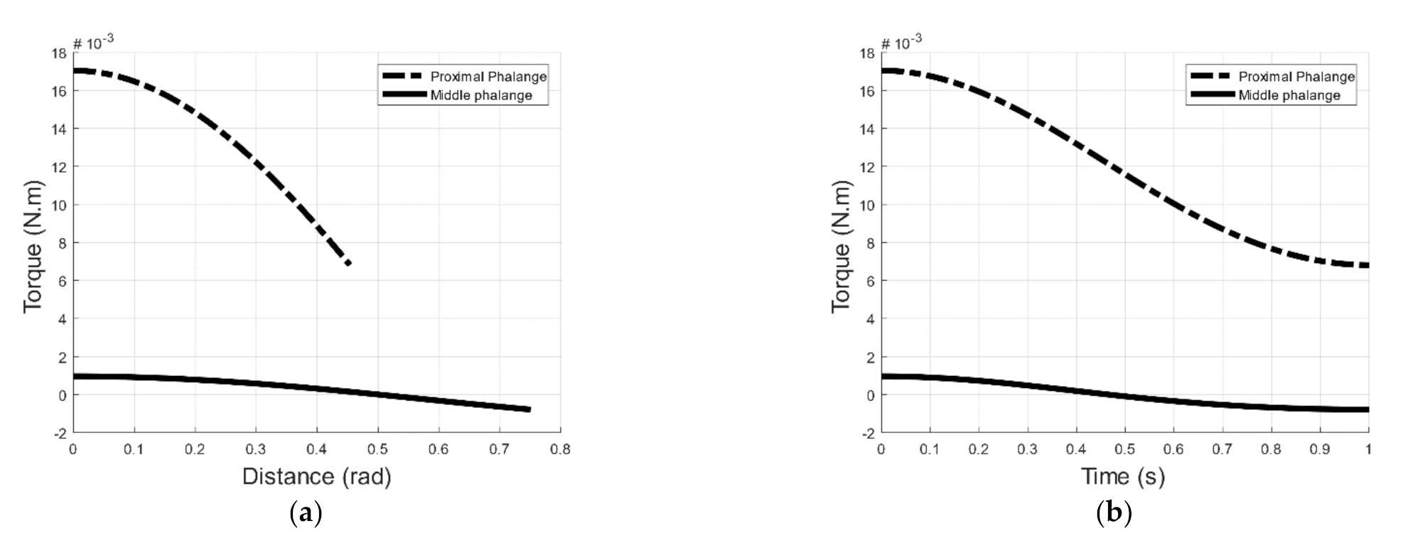
Taking the parameters d1 = 0.0203 m, d2 = 0.0187 m, and d3 = 0.0202 m for the length of proximal, middle, and distal phalanges, respectively, as shown in Table 1, and Equations (25)–(30), the results are shown in Table 4. It can be seen that the values of joint coordinates q1, q2, and q3 for rotation angles of MCP, PIP, and DIP joints coincide with the range of motion obtained for the position analysis in Section 4.1.

4.3. Dynamics

For dynamic simulations, parameters, such as mass, moment of inertia, and center of mass of the elements to be analyzed for the proximal and middle phalanges, were taken from the CAD design proposed in Solidworks, as shown in Table 5.
To first validate the dynamics, a sinusoidal function was developed to represent the movement of each joint as = 13 π sin π t / 90 / 90 and = 43 π sin π t / 90 / 180 for the proximal and middle phalanxes, see Figure 7.
According to the algorithm described in Section 3.3, using Equations (31)–(39) and implementing the values from Table 5, the values shown in Figure 8 and Table 6 were obtained.

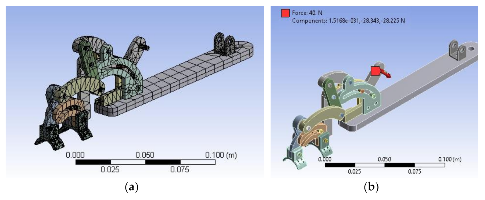
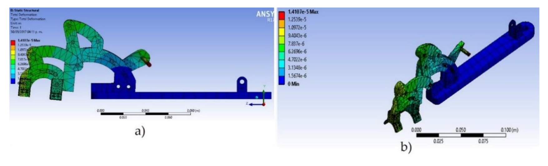
4.4. Structural Analysis

ANSYS software was used for finite element analysis. For this simulation, only the elements of the mechanical structure were contemplated and the CAD design from ANSYS is shown in Figure 9a. The main base of the mechanism was taken as a fixed support and the friction forces between the elements were not included. A force exerted on the bolt that joins the linear actuator with the mechanism that moves to the proximal phalanx was applied. The force exerted on that element was taken with respect to a maximum force exerted by a selected linear actuator (40 N), see Figure 9b. The average size of the mesh elements was 2.088 × 10⁻⁴ m. The material used to make the 3D print was ABS.
In the simulation of static forces, only total strain analysis was considered. Using these criteria, the feasibility of the design was evaluated, focusing on total deformation. As can be seen in Figure 10a,b, the deformation magnitudes for each part of the mechanism are defined according to the colors shown in the column on the left, where the pieces in blue are the ones that suffered less deformation; the more deformation there was the more the pieces changed color, and those presented in red were the pieces that suffered more deformation. The maximum deformation obtained was 1.41073 × 10⁻⁵ m, and is present on the “pin slide” element, which is the bolt that joins the linear actuator with the elements that move to the proximal phalanx.
As result, a one-DOF prototype mechanism for a finger was developed, where the links, together with the base, were manufactured using ABS plastic by means of a 3D printer, see Figure 11. The bolts were made of aluminum alloy using a lathe, and their dimensions are based on those of the design.

5. Discussion

The use of a robotic device for hand rehabilitation is a new development to support the recovery of hand functions following a stroke. Exoskeleton design in the literature requires deep knowledge of physical human–robot interactions, biomechanics, rehabilitation, actuators, sensors, and control. The main goal is to design effective, lightweight, and portable robotic devices for hand rehabilitation. However, most of the reported hand exoskeleton rehabilitation devices, with very few exceptions, lack portability, have many DOF, and, at the same time, they are voluminous, heavy, complex, and expensive [2,3,4,5,6].
The exoskeleton proposed in this work is designed to achieve a lightweight device for the hand of the patient so that it can be worn more easily. It can be manufactured with a 3D printer and its lightness allows it to be used as a splint. The exoskeleton consists of a linkage-slide mechanism with one DOF that provides extension/flexion assistance for the finger. The use of the linkage-slide mechanism not only realizes the purpose, but also makes the rotation center of the linkage structure coincide with the rotation axis of the MCP, PIP, and DIP finger joints. The structure is, therefore, more compact and lightweight than those mentioned in other works [18,19,20,21,22,23,24,25,26,27,28].
Currently, the cost of complex robotic devices makes them unsuitable for use in a domestic or local clinical setting (e.g., [2]). Developing lower-cost devices could help to address this and the development of a low-cost prototype robotic device for rehabilitation to help people to recover finger functions and practice normal daily activities would be of use.

6. Conclusions

As discussed in the previous sections, the CAD design of a one-DOF exoskeleton for a finger’s movement was presented. The prototype was based on the anthropometric measurements of a finger, as well as the movement ranges of the joints (MCP, PIP, and DIP joints).
In the development of position and displacement analyses, the link position of the proposed design was determined concerning a driving link position, which, in this case, was the linear actuator. The analysis presented a challenge since the mechanism configuration meant that obtaining the position equations of the main elements had considerable complexity. However, the equation validation indicates a good analysis.
The inverse kinematic analysis achieved the equations that described the prototype position to determine the value of the articular coordinates with respect to the finger end coordinates. Additionally, inverse kinematic analysis was performed using the geometric approach, finding a close equation. The Newton–Euler approach was applied for dynamic analysis. As a result of the simulations, pairs were obtained, for example, for the movement of the MCP joint. The maximum obtained torque was 0.0170 N·m.
The simulation developed through SimMechanics allowed mechanism movement according to the proposed ranges of motion. Additionally, structural analysis simulation was carried out using ANSYS software. With the obtained results, it was possible to determine the link deformation that occurs in the mechanism when an external force is applied from the Actuonix linear actuator, which was applied in the bolt that joins the linear actuator with the mechanism that exerts movement on the proximal phalanx. The used force value was 40 N, which is equivalent to the maximum exerted force by the actuator. The obtained results indicated that the maximum obtained deformation had a value of 1.41073 × 10⁻⁵ m, generated in the bolt that joins the linear actuator with the mechanism that exerts proximal phalanx movement. With these data it could be concluded that the maximum deformation present in the mechanism elements was relatively small and that the use of ABS plastic in the prototype was viable.
In future work, improvements to the proposed design are expected to allow satisfactory functionality to be obtained. Likewise, various improvements are contemplated, which include better design parameter definitions and mechanism dimensions based on the anthropometric measurements of people of all ages, with the objective that the mechanism have a good performance for application in rehabilitation, to adapt sensor implementation designs that allows monitoring the movement of fingers phalanges. In addition, where the mechanism exerts movement, the use of another material type that allows optimal link manufacturing of the mechanism and to implement the proposed linear actuator in the prototype should be aims.

Author Contributions

C.H.-S. implemented the mathematical modeling, developed the simulations, and wrote the paper. Y.A.D. reviewed the mathematical modeling and simulations. A.R.S. and R.S. analyzed and reviewed the paper structure. L.C.F.-H. and A.V.-M. carried out the literature review and recommended a suitable journal. All authors have read and agreed to the published version of the manuscript.

Funding

This research received no external funding.

Institutional Review Board Statement

Not applicable.

Informed Consent Statement

Not applicable.

Data Availability Statement

Not applicable.

Conflicts of Interest

The authors declare no conflict of interest.

References

  1. Siciliano, B.; Khatib, O. Springer Handbook of Robotics; Springer: Berlin/Heidelberg, Germany, 2016. [Google Scholar]
  2. Wege, A.; Zimmermann, A. Electromyography sensor based control for a hand exoskeleton. In Proceedings of the IEEE International Conference on Robotics and Biomimetics, Sanya, China, 15–18 December 2007; pp. 1470–1475. [Google Scholar]
  3. Li, J.; Zheng, R.; Zhang, Y.; Yao, J. Ihandrehab: An interactive hand exoskeleton for active and passive rehabilitation. In Proceedings of the IEEE International Conference on Rehabilitation Robotics, Zurich, Switzerland, 29 June–1 July 2011; pp. 1–6. [Google Scholar]
  4. Ottobock. WaveFlex Hand CPM Device. Available online: https://www.medcomgroup.com/content/QAL%20Waveflex%206000X%20Hand%20CPM%20Operations%20Manual.pdf (accessed on 17 March 2021).
  5. Tong, K. An intention driven hand functions task training robotic system. In Proceedings of the 32nd Annual International Conference of the IEEE EMBS, Buenos Aires, Argentina, 11 November 2010; pp. 3406–3409. [Google Scholar]
  6. Lambercy, O.; Schröder, D.; Zwicker, S.; Gassert, R. Design of a thumb exoskeleton for hand rehabilitation. In Proceedings of the International Convention on Rehabilitation Engineering and Assistive Technology (i-CREATe), Zurich, Switzerland, 13 September 2013; Available online: https://www.researchgate.net/publication/259910946_Design_of_a_thumb_exoskeleton_for_hand_rehabilitation (accessed on 4 June 2020).
  7. Polygerinos, P.; Wang, Z.; Galloway, K.C.; Wood, R.J.; Walsh, C.J. Soft robotic glove for combined assistance and at-home rehabilitation. Robot. Autonom. Syst. 2015, 73, 135–143. [Google Scholar] [CrossRef] [Green Version]
  8. Lucas, L.; DiCicco, M.; Matsuoka, Y. An emg-controlled hand exoskeleton for natural pinching. J. Robot Mechatron. 2004, 16, 482–488. [Google Scholar] [CrossRef] [Green Version]
  9. Brokaw, E.; Black, I.; Holley, R.; Lum, P. Hand spring operated movement enhancer (handsome): A portable, passive hand exoskeleton for stroke rehabilitation. IEEE Trans. Neuro Syst. Rehabil. Eng. 2011, 19, 391–399. [Google Scholar] [CrossRef] [PubMed]
  10. Borboni, A.; Mor, M.; Faglia, R. Gloreha—Hand Robotic Rehabilitation: Design, Mechanical Model, and Experiments. J. Dyn. Syst. Meas. Control. 2016, 138, 111003. [Google Scholar] [CrossRef]
  11. Hasegawa, Y.; Mikami, Y.; Watanabe, K.; Sankai, Y. Five-fingered assistive hand with mechanical compliance of human finger. ICRA 2008. In Proceedings of the IEEE International Conference on Robotics and Automation, Pasadena, CA, USA, 19–23 May 2008; pp. 718–724. [Google Scholar]
  12. Chiri, A.; Vitiello, N.; Giovacchini, F.; Roccella, S.; Vecchi, F.; Carrozza, M.C. Mechatronic Design and Characterization of the Index Finger Module of a Hand Exoskeleton for Post-Stroke Rehabilitation. IEEE/ASME Trans. Mechatron. 2012, 17, 884–894. [Google Scholar] [CrossRef]
  13. Cempini, M.; De Rossi, S.M.M.; Lenzi, T.; Cortese, M.; Giovacchini, F.; Vitiello, N.; Carrozza, M.C. Kinematics and design of a portable and wearable exoskeleton for hand rehabilitation. In Proceedings of the IEEE International Conference on Robotics and Automation, Seattle, WA, USA, 24–26 June 2013; pp. 1–6. [Google Scholar]
  14. Festo. Festo Exohand Characteristics. 2012. Available online: https://www.festo.com/group/en/cms/10233.htm (accessed on 4 June 2020).
  15. Kazerooni, H. Exoskeletons for human power augmentation. In Proceedings of the IEEE/RSJ International Conference on Kinematics and Design of a Portable and Wearable Exoskeleton for Hand Rehabilitation, Edmonton, AB, Canada, 2–6 August 2005; pp. 3459–3464. [Google Scholar]
  16. Jamshed, I.A.; Tsagarakis Nikos, G.; Caldwell, D.G. A portable rehabilitation device for the hand. In Proceedings of the 32nd Annual International Conference of the IEEE EMBS, Buenos Aires, Argentina, 11 November 2010; pp. 3694–3697. [Google Scholar]
  17. Schabowsky, C.; Godfrey, S.B.; Holley, R.J.; Lum, P.S. Development and pilot testing of HEXORR: Hand EXOskeleton Rehabilitation Robot. J. Neuroeng. Rehabil. 2010, 17, 6–28. [Google Scholar] [CrossRef] [PubMed] [Green Version]
  18. Iqbal, J.; Tsagarakis, N.; Caldwell, D. Human hand compatible underactuated exoskeleton robotic system. Electron. Lett. 2014, 50, 494–496. [Google Scholar] [CrossRef]
  19. Wege, A.; Kondak, K.; Hommel, G. Mechanical design and motion control of a hand exoskeleton for rehabilitation. In Proceedings of the IEEE International Conference on Mechatronics and Automation, Niagara Falls, ON, Canada, 29 July–1 August 2005; Volume 1, pp. 155–159. [Google Scholar]
  20. Worsnopp, T.; Peshkin, M.; Colgate, J.; Kamper, D. An actuated finger exoskeleton for hand rehabilitation following stroke. In Proceedings of the IEEE 10th International Conference on Rehabilitation Robotics, Noordwijk, The Netherlands, 14 January 2008; pp. 896–901. [Google Scholar]
  21. Iqbal, J.; Tsagarakis, N.; Caldwell, D. A human hand compatible optimized exoskeleton system. In Proceedings of the IEEE International Conference on Robotics and Biomimetics, Tianjin, China, 14–18 December 2010; pp. 685–690. [Google Scholar]
  22. Fontana, M.; Dettori, A.; Salsedo, F.; Bergamasco, M. Mechanical design of a novel hand exoskeleton for accurate force displaying. In Proceedings of the IEEE International Conference on Robotics and Automation, Kobe, Japan, 12–17 May 2009; pp. 1704–1709. [Google Scholar]
  23. Burton, T.; Vaidyanathan, R.; Burgess, S.; Turton, A.; Melhuish, C. Development of a parametric kinematic model of the human hand and a novel robotic exoskeleton. In Proceedings of the IEEE International Conference on Rehabilitation Robotics, Zurich, Switzerland, 29 June–1 July 2011; pp. 1–7. [Google Scholar]
  24. Fontana, M.; Fabio, S.; Marcheschi, S.; Bergamasco, M. Haptic Hand Exoskeleton for Precision Grasp Simulation. J. Mech. Robot. 2013, 5, 041014. [Google Scholar] [CrossRef] [Green Version]
  25. Aubin, P.; Petersen, K.; Sallun, H. A pediatric robotic thumb exoskeleton for at-home rehabilitation. Int. J. Intell. Comput. Cybern. 2014, 7, 233–252. [Google Scholar] [CrossRef]
  26. Wu, J.; Huang, J.; Wang, Y.; Xing, K. RLSESN-based PID adaptive control for a novel wearable rehabilitation robotic hand driven by PM-TS actuators. Int. J. Intell. Comput. Cybern. 2012, 5, 91–110. [Google Scholar] [CrossRef]
  27. Enriquez, S.C.; Narváez, Y.; Vivas, O.A.; Diez, J.; Badesa, F.J.; Sabater, J.M.; Garcia-Aracil, N. Sistema robótico de tipo exoesqueleto para rehabilitación de la mano 2014. In Actas de las XXXV Jornadas de Automática; Comité Español de Automática de la IFAC: Madrid, Spain, September 2014. [Google Scholar]
  28. Yap, H.K.; Lim, J.H.; Nasrallah, F.; Goh, J.C.H.; Yeow, R.C.H. A Soft Exoskeleton for Hand Assistive and Rehabilitation Application using Pneumatic Actuators with Variable Stiffness. In Proceedings of the IEEE International Conference on Robotics and Automation, Seattle, WA, USA, 26–30 May 2015. [Google Scholar]
  29. Matheson, E.; Brooker, G. Assistive Rehabilitation Robotic Glove. In Proceedings of the Australasian Conference on Robotics and Automation, Melbourne, Australia, 7–9 December 2011; pp. 1–10. [Google Scholar]
  30. Cempini, M.; Marzegan, A.; Rabuffetti, M.; Cortese, M.; Vitiello, N.; Ferrarin, M. Analysis of relative displacement between the HX wearable robotic exoskeleton and the user’s hand. J. Neuroeng. Rehabil. 2014, 11, 1–8. [Google Scholar] [CrossRef] [PubMed] [Green Version]
  31. Stoll, W. New scope for Interaction between Humans and Machines; Festo AG & Co. KG: Esslingen, Germany, 2012. [Google Scholar]
  32. Ma, Z.; Ben-Tzvi, P.; Danoff, J. Modeling human hand and sensing hand motions with the five-fingered haptic glove mechanism. In Proceedings of the ASME International Design Engineering Technical Conferences & Computers and Information in Engineering Conference, Buffalo, NY, USA, 17–20 August 2014. [Google Scholar]
  33. Wang, F.; Shastri, M.; Jones, L.C.; Gupta, V.; Osswald, C.; Kang, X.; Kamper, G.D.; Sarkar, N. Design and control of an actuated thumb exoskeleton for hand rehabilitation following stroke. In Proceedings of the IEEE International Conference on Robotics and Automation, Shanghai, China, 9–13 May 2011. [Google Scholar]
  34. Jiting, L.; Shuang, W.; Ju, W.; Ruoyin, Z.; Yuru, Z.; Zhongyuan, C. Development of a Hand Exoskeleton System for Index Finger Rehabilitation. Chin. J. Mech. Eng. 2011, 24, 223–233. [Google Scholar]
  35. Iqbal, J.; Khan, H.; Tsagarakis, G.N. A novel exoskeleton robotic system for hand rehabilitation conceptualization to prototyping. Elsevier Biocybern. Biomed. Eng. 2014, 34, 79–89. [Google Scholar] [CrossRef]
  36. Available online: https://freepikpsd.com/handpng/639314/ (accessed on 20 March 2021).
  37. Actuonix. Available online: https://www.actuonix.com/L12-Micro-Linear-Actuators-s/1821.htm (accessed on 12 April 2021).
  38. Kiat, N.P.; Saptari, A. Hand Anthropometry: A Descriptive Analysis on Elderly Malaysians. In Adult Elderly Anthropometry; 2013; pp. 193–198. [Google Scholar]
  39. Myszka, D.H. Machines and Mechanisms, 4th ed.; Pearson: Mexico City, Mexico, 2012. [Google Scholar]
Figure 1. A general outline of the proposed design [36].
Applsci 11 04145 g001
Figure 2. (a) Proposed exoskeleton (general view) and (b) exploded view of the single DOF.
Applsci 11 04145 g002
Figure 3. (a) Initial position for proposed mechanism from a lateral view and (b) analysis of the final position of the mechanism.
Applsci 11 04145 g003
Figure 4. Inverse kinematics model.
Applsci 11 04145 g004
Figure 5. Dynamic model.
Applsci 11 04145 g005
Figure 6. Simulation results for the proposed exoskeleton: (a) initial position and (b) final position.
Applsci 11 04145 g006
Figure 7. Proximal and media phalanges displacement.
Applsci 11 04145 g007
Figure 8. Torque obtained from Newton–Euler formulation for the movement of the proximal and middle phalanxes of the proposed exoskeleton; (a) describes the torque vs. displacement, and (b) describes the torque vs. time.
Applsci 11 04145 g008
Figure 9. (a) CAD design in ANSYS exported from SolidWorks. (b) Maximum force by a linear actuator.
Applsci 11 04145 g009
Figure 10. Results obtained in the “total deformation” simulation, where (a) shows the side mechanism view and (b) shows the same isometric view.
Applsci 11 04145 g010
Figure 11. Physical prototype for the proposed design. (a) Initial position and (b) final position.
Applsci 11 04145 g011
Table 1. Review of exoskeleton for hand rehabilitation.
SystemDeveloperForce TransmissionDOFActuatorMaterialRange
Movement
WaveFlexMedcom groupTransmission 1DC motor-MCP: 0–90°
PIP: 0–110°
DIP: 0–70°
HandSOMECatholic University of AmericaLinkage 1Elastic cordsAluminumCMC: 52°; MCP: 90°
GlorehaUniversita degli Studi di BresciaCable1Pneumatic--
LambercyRehabilitation Engineering Lab
ETH Zurich, Switzerland
Fourbar
linkage
1Linear
actuator
-CMC 40°
HEXOSYSUniversity of Genova, ItalyLinkage 1DC motorPlastic
Aluminum
-
IOTAWyss Institute for Biologically Inspired Engineering, HarvardSpring-return cable transmission2Dynamixel AX-12A servo motors.Delrin and AluminumCMC: 67°; MCP: 67°
PM-TSHuazhong University of Science and TechnologyCable2PneumaticThermoplasticMCP: 70°; PIP: 90°
EXOGLOVENational University of SingaporePneumatic bending actuators3PneumaticElastomeroDIP: 50.8°
PIP: 45.4°
MCP: 68.1°
ASSISTITIVE REHABILITATION ROBOTIC GLOVEAustralian Centre for Field RoboticsPneumatic muscle3Pneumatic--
HXScuola Superiore Sant’AnnaPulleys and a cable2DC Motor--
EXOHANDFestoDFK-10 cylinders from FESTO-PneumaticPolyamide-
FIVE-FINGERED HAPTIC GLOVE DESIGNGeorge Washington UniversityLinkage3DC MotorThermoplasticMCP 60°
DIP 50°
PIP 30°
ATXTRUMPF Photonics Inc.Linkage5DC MotorAluminum-
AFX-Cable3DC Servomotor Aluminum, D2 steelMCP: −15°–75°
PIP: 0–90°
DIP: 0–75°
EXORR-Linkage Brushless motorAluminum-
Table 2. Length and range of movements of the hand phalanges [16].
Link/PhalanxJointLength (m)Range Movement
Proximal
L1
MCPIndex 0.023826°
Middle0.0254
Ring 0.0220
Little 0.0181
Thumb 0.0288
Media
L2
PIPIndex 0.018743°
Middle0.0224
Ring 0.0212
Little 0.0163
Thumb N/A
Distal
L3
DIPIndex 0.022443°
Middle0.0237
Ring 0.0214
Little 0.0202
Thumb 0.0289
Table 3. Range from position analysis vs. range proposed.
PhalangeRange of Motion (°)
ProposedDistanceObtainedDistance
Proximal0–262645.06–70.1125.05
Media0–4343110.07–152.7642.69
DistalN/AN/AN/AN/A
Table 4. Values from inverse kinematics analysis.
JointValueLength (m)Coordinator (m)
MCP(q1)25.89°0.0203X1Y1Z1
PIP(q2)42.37° 0.01830.0089N/A
DIP(q3)43.51°0.0187X2Y2Z2
N/AN/AN/A
0.0202X3Y3Z3
0.01740.0452N/A
Table 5. Dynamic simulation parameters.
PhalangesL1/MCPL2/PIPL3/DIP
Length (m)0.02380.0187-
Joint (rad)13π/9043π/180-
Mass (kg)0.0947850.008337-
Center of mass0.0073360.0006577-
InertiaIxx0.0012890.0006562-
Iyy0.0012860.0006562-
Izz0.000004040.00000240-
Table 6. Torque for each phalange.
PhalangeJointsTorque (Nm)
MaximumMinimum
ProximalMCP0.01700.0068
MediaPIP9.5847 × 10−4−7.9009 × 10⁻⁴
Publisher’s Note: MDPI stays neutral with regard to jurisdictional claims in published maps and institutional affiliations.

