Article

Field Test for a Base Isolation Structure on Condition of Horizontal and Initial Displacement

1
College of Civil Engineering, Fuzhou University, Fuzhou 350108, China
2
Fujian Provincial Key Laboratory on Multi-Disasters Prevention and Mitigation in Civil Engineering, Fuzhou 350108, China
*
Author to whom correspondence should be addressed.
Appl. Sci. 2022, 12(1), 232; https://doi.org/10.3390/app12010232
Submission received: 2 December 2021 / Revised: 17 December 2021 / Accepted: 20 December 2021 / Published: 27 December 2021
(This article belongs to the Special Issue Diagnostics and Monitoring of Steel and Concrete Structures)

Abstract

:
There are a few isolated structures that have been subjected to seismic testing. An isolated structure is incapable of tracking, adjusting, and controlling its dynamic characteristics. As a result, field evaluations of solitary structures’ dynamic characteristics are important. The horizontal initial displacement of a base isolation kindergarten made of 46 isolation bearings is 75 mm. The method for creating the horizontal initial displacement condition is illustrated, as are the primary test findings. Horizontal initial displacement is accomplished with the assistance of a reaction wall, rods, and hydraulic pump system. To begin, we removed the building using hydraulic jacks to produce horizontal displacement of the isolation layer and then attached rods to support the building. The rods were then shot and unloaded, causing the building to shake freely, and its dynamic response and other parameters were tested. The results indicate that the natural vibration period of an isolated structure is much greater than the natural vibration period of a seismic structure. The isolation layer’s hysteretic curve as completely filled; upon unloading, the isolation layer as promptly reset; the dynamic response control effect of each was visible, but the top floor’s acceleration was magnified by approximately 1.27 times.

1. Introduction

The application of engineering structure isolation technology has developed rapidly throughout the world in recent decades. While an increasing number of structures incorporate seismic isolation technology, only a few isolated structures have been tested by earthquakes. For example, during the 1994 Los Angeles earthquake of magnitude 6.7, the main structure of USC University Hospital was not damaged, the hospital continued to operate normally, and the hospital became a disaster relief center [1,2]. During the 1995 Hanshin earthquake of magnitude 7.2 in Japan, the Western Post Building, Japan’s largest seismic isolation structure, remained intact following the earthquake and played a significant role in the disaster relief [3,4]. During the 2008 Wenchuan earthquake of magnitude 8.0 in China, several residential buildings with base-isolation technology remained intact [5]. These few findings suggest that the isolation of the building is basically as designed. However, the vast majority of isolated structures have not experienced earthquakes, and the actual isolation structure’s dynamic characteristics lack the ability to track, regulate, and control. As a result, it is necessary to validate the actual isolation structure’s dynamic characteristics and seismic performance through field testing. The dynamic characteristics of the structure, including natural frequency, vibration mode and damping ratio, are the decisive factors of the structural response during earthquake [6]. The methods to test the dynamic characteristics of structures include environmental excitation, initial displacement, steady-state sine wave excitation, and artificial blasting excitation methods. The test methods can be selected according to the required purpose.
The initial displacement method is a technique for determining the dynamic performance of a specimen (building structure) by applying an initial displacement and then abruptly releasing it to cause it to vibrate [7]. There are few field tests and analyses of isolated structures under the horizontal initial displacement conditions all over the world. In the literature [8,9], the structural displacement and abrupt release tests of the Ancona Telecom Building in Italy were conducted using a horizontal initial displacement of 100 mm. The test results indicate that when exposed to ambient vibration, the dynamic characteristics of isolated and nonisolated structures are comparable. When the isolation layer deforms significantly, the structure’s first period is approximately 1.6 times longer than that under ambient vibration, indicating a high damping ratio. Franco Braga and Michelangelo Laterza [10,11,12] conducted a release test on a residential building in southern Italy using a horizontal displacement of 20 mm as the initial displacement (corresponding to 20% of the bearing shear strain). The test results indicate that when the isolation layer deforms little, the structure’s first cycle is approximately 1.21 times longer than that under ambient vibration, indicating a high damping ratio. Wei Lushun [13] tested and analyzed energy consumption and floor acceleration response of the isolation structure of an earthquake prevention and disaster reduction command center in China. The test results indicate that the isolated structure’s predominant period is longer than that of the seismic structure, and the damping of each vibration mode is rather large. He Yingmiao [14] conducted the field reciprocating loading dynamic test on a base-isolated 15-story steel structure in Yunnan Province, China. Several parameters, including the natural vibration period of the structure and the acceleration response of each floor, of the structure under various working conditions were measured. Further, the dynamic characteristics and seismic response of the isolated structure obtained from the actual test are compared with the numerical model calculation results of the isolated structure and found that the test results are in good agreement with numerical calculations.
The testing of the actual isolation structure outlined above has several limitations. On the one hand, the horizontal initial displacement values used in the majority of tests are too modest, and the isolation bearings with lead core were not fully utilized, resulting in an inaccurate representation of the structure’s dynamic characteristics. On the other hand, the unloading period of hydraulic jacks is quite long, resulting in the slow displacement recovery for isolation bearing, and the test method is insufficiently realistic. To overcome the constraint of a too small horizontal displacement value, the initial displacement value of the test in this paper was set to 100% of the shear strain of the isolation bearing (equivalent to the medium earthquake level in the Chinese code [15]), in order to obtain the structure’s natural vibration characteristics and further analyze the reset performance and hysteretic energy dissipation capacity. Additionally, the process for unloading has been improved following the introduction of hydraulic jacks. Prior to unloading, concrete rods are employed to support the superstructure instead of hydraulic jacks, and the concrete rods are promptly detonated to cause the building to vibrate freely, emulating the isolated structure’s true dynamic characteristics.

2. Overview of Test Project

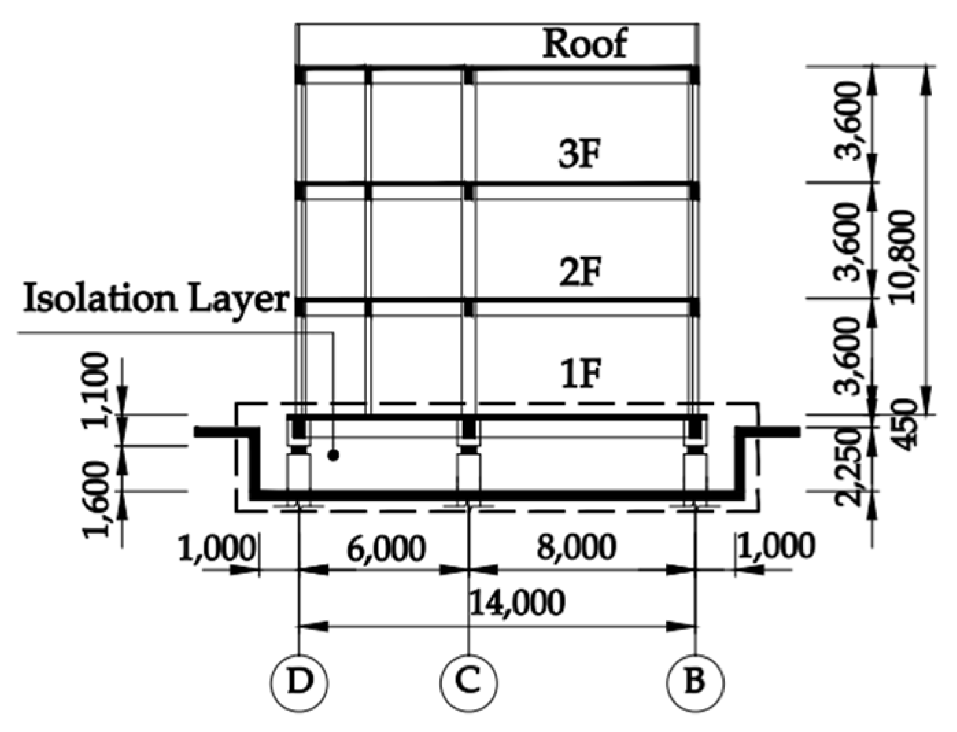
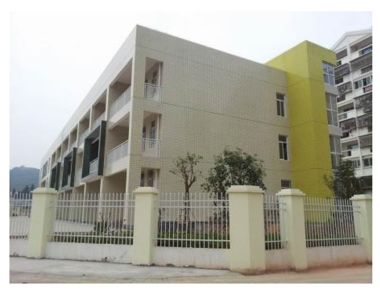
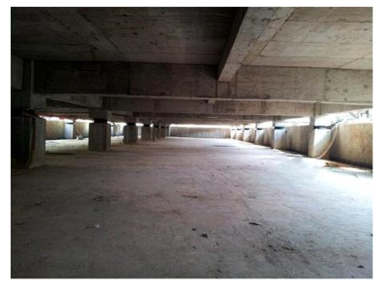
In southern China, there is kindergarten which is a three-story structure measuring 65.70 m east to west (X direction) and 14.80 m–21.60 m north to south (Y direction is north). The total size of the structure is approximately 3586 m2. Figure 1 illustrates the building’s ground floor plan, whereas Figure 2 illustrates the building’s section. Figure 3 illustrates the completed southeast façade of the structure. According to the Chinese code [15], the seismic fortification class of the building is B, the seismic fortification intensity of the site on which the building is located is seven, the design fundamental seismic acceleration is 0.15 g, the design earthquake group is group two, the site category is II, and the characteristic period is 0.35 s. The basic wind pressure is 0.80 kN/m2. The building adopts reinforced concrete frame structure and applies foundation isolation technology. Figure 4 illustrates the isolation overhaul layer.
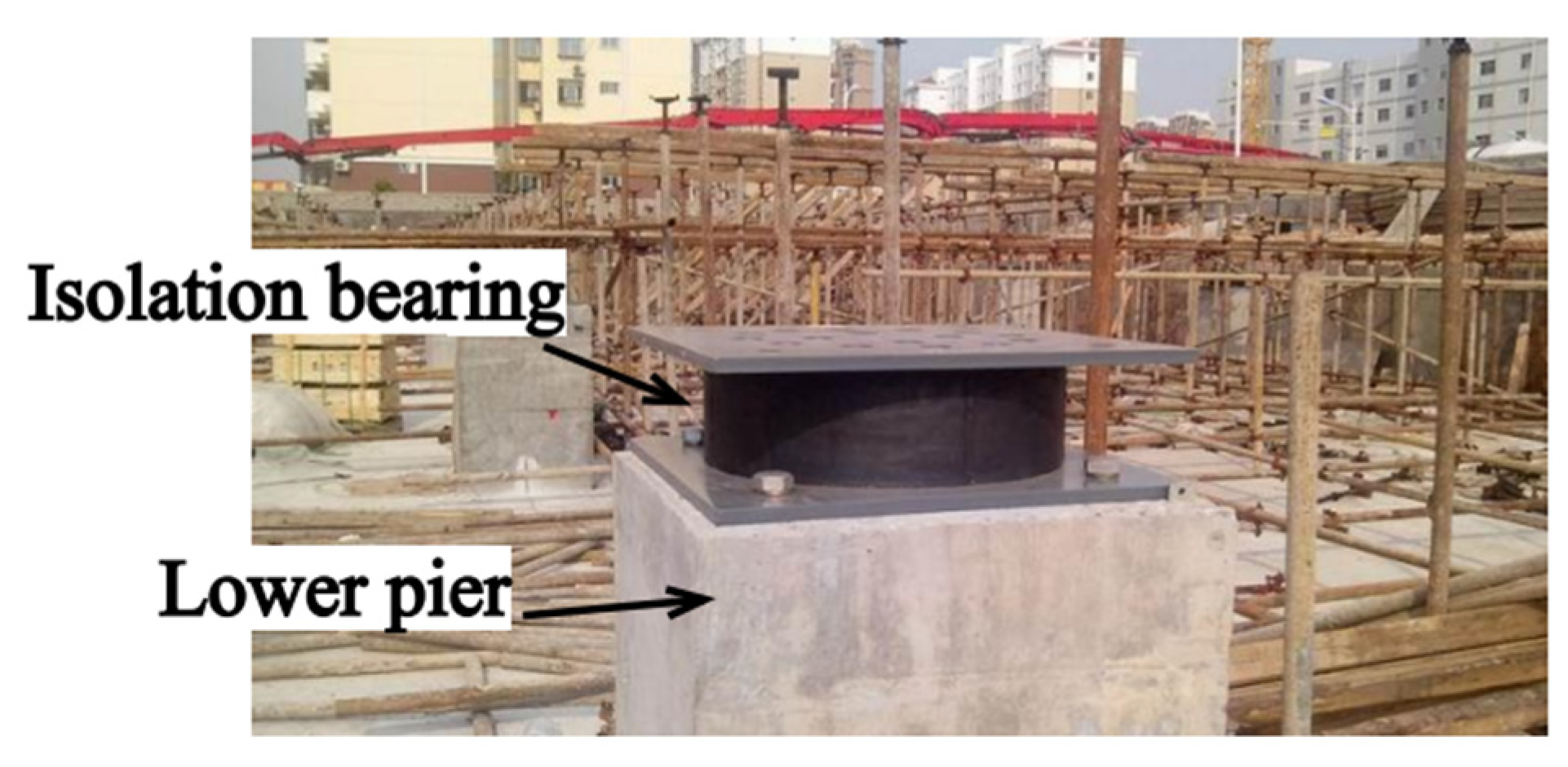
The building’s isolation layer comprises 46 low-hardness isolation rubber bearings (hereinafter referred to as isolation bearings), including 20 LNR500 (regular rubber bearing) and 26 LRB400 (rubber bearing with lead core). The rubber used in the isolation bearings is chemically vulcanized to achieve stable performance [16,17], and its shear elastic modulus is 0.392 N·mm−2. LRB is positioned in the side and corner columns, whereas LNR is positioned in the center column [18]. Table 1 summarizes the specifications and mechanical characteristics of isolation bearings. Figure 5 and Figure 6 illustrate the isolation bearings’ plane layout, construction, and installation.
The location of the building falls under a 7 degree seismic fortification zone, which belongs to the medium intensity area. The Chinese code [15] considers the horizontal earthquake, instead of the vertical one [19]. Therefore, the field dynamic characteristics of the isolated base structure were investigated in this study prior to the building’s completion under the condition of a horizontal starting displacement of 75 mm (LRB400 shear strain up to 75/68.60 = 109%).
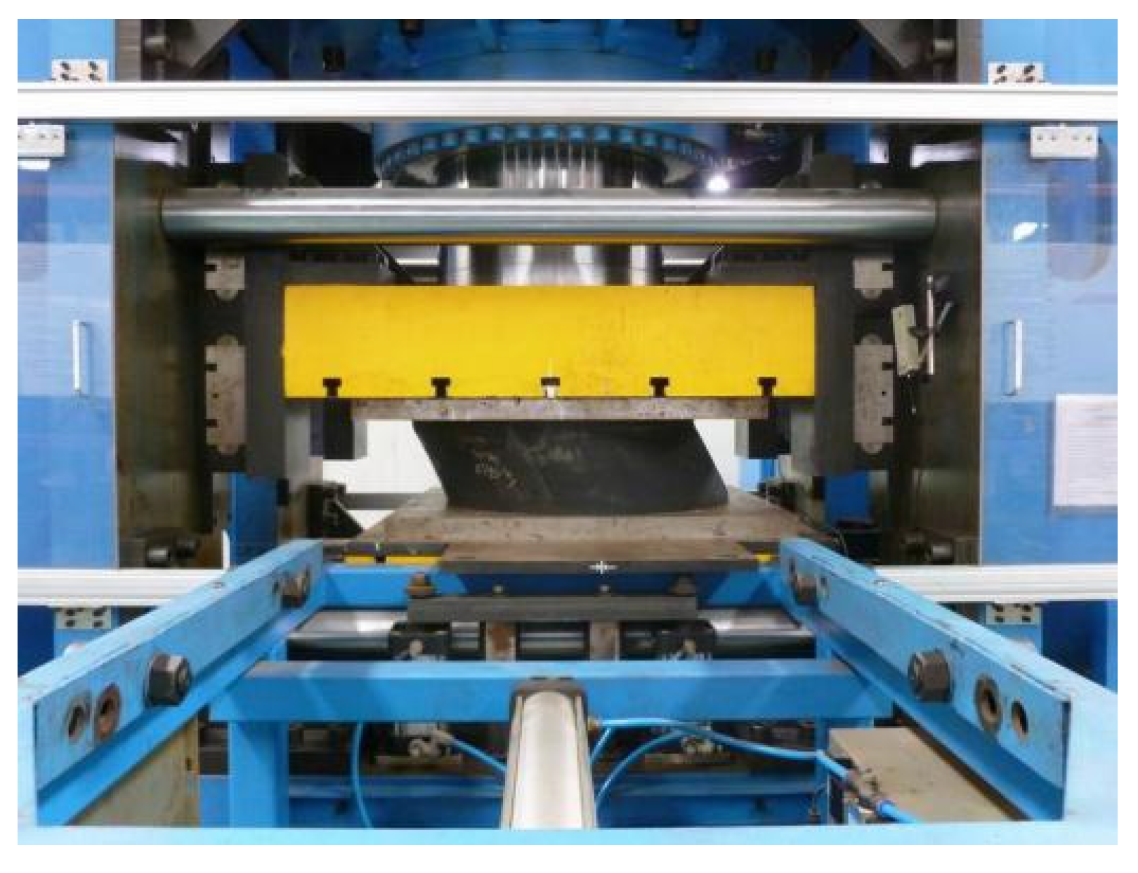
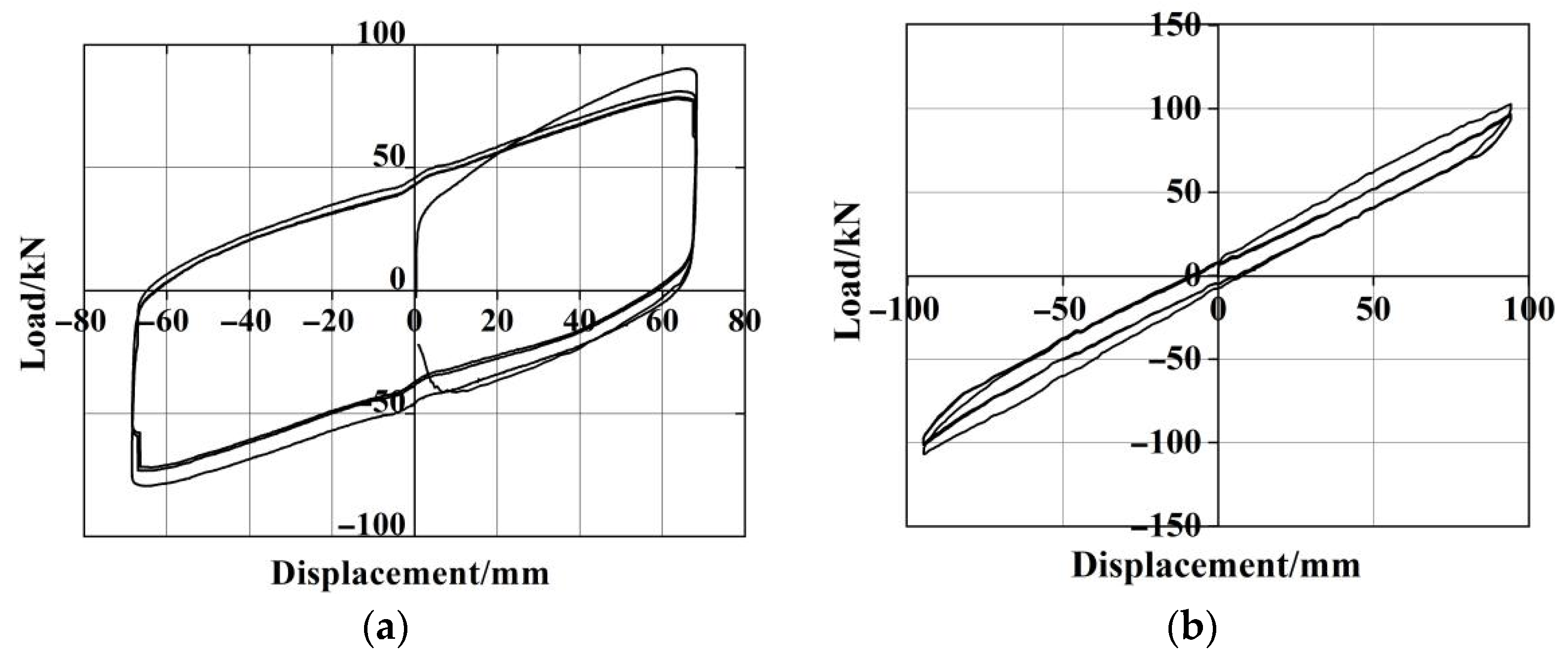
Before installation, the isolation bearings were inspected in the presence of a third party. The isolation bearing’s vertical stiffness and horizontal shear performance were determined in the laboratory using a 2500 t two-dimensional loading test machine (Figure 7). The results indicated that the performance error was within ±10% of the criteria of the Chinese code [20], indicating that the isolation bearings used were certified. Figure 8 illustrates the isolation bearing’s hysteretic curve.

3. Devices Setup and Field Test

3.1. Field Test Instruments and Related Equipment

The test was conducted using hydraulic jacks and a hydraulic pump system, a DH612 sensor, an electric displacement meter, a computer, a DHDAS dynamic signal acquisition and analysis system, DHMA modal analysis software, and displacement dynamic acquisition and analysis software. The hydraulic pump system generates horizontal initial displacement of the isolation layer and a DH612 sensor is used to detect the floor’s vibration signal, including speed and acceleration. The electric displacement meter is installed at the upper pier position on the I1, I2, I3, and I4 isolation bearings (Figure 5) to monitor and record the horizontal displacement of the isolation layer and then transmit the measured displacement of the isolation layer to the displacement acquisition and analysis software. The data acquisition center comprises a data acquisition box and computer, which are used to load the dynamic signal acquisition and analysis system, the modal analysis software, and the displacement dynamic acquisition and analysis software. Figure 9 illustrates field testing instruments and related equipment.

3.2. Sensors Arrangement

In order to maximize measurement convenience and accuracy, the measuring points shall be located as close to the building’s end as possible [21]. Accordingly, the measurement locations for this test are located at the north floor intersections of axis ① and ⑦. Each level shall have a pair of acceleration sensors and a pair of speed sensors, which shall be numbered according to the scheme described in Table 2. The sensor is connected to the data acquisition center located in the basement in order to collect acceleration and velocity time-history curves before and during structural displacement reset. Figure 10 illustrates the sensor configuration.

3.3. Design and Test of Horizontal Displacement Loading and Unloading Device

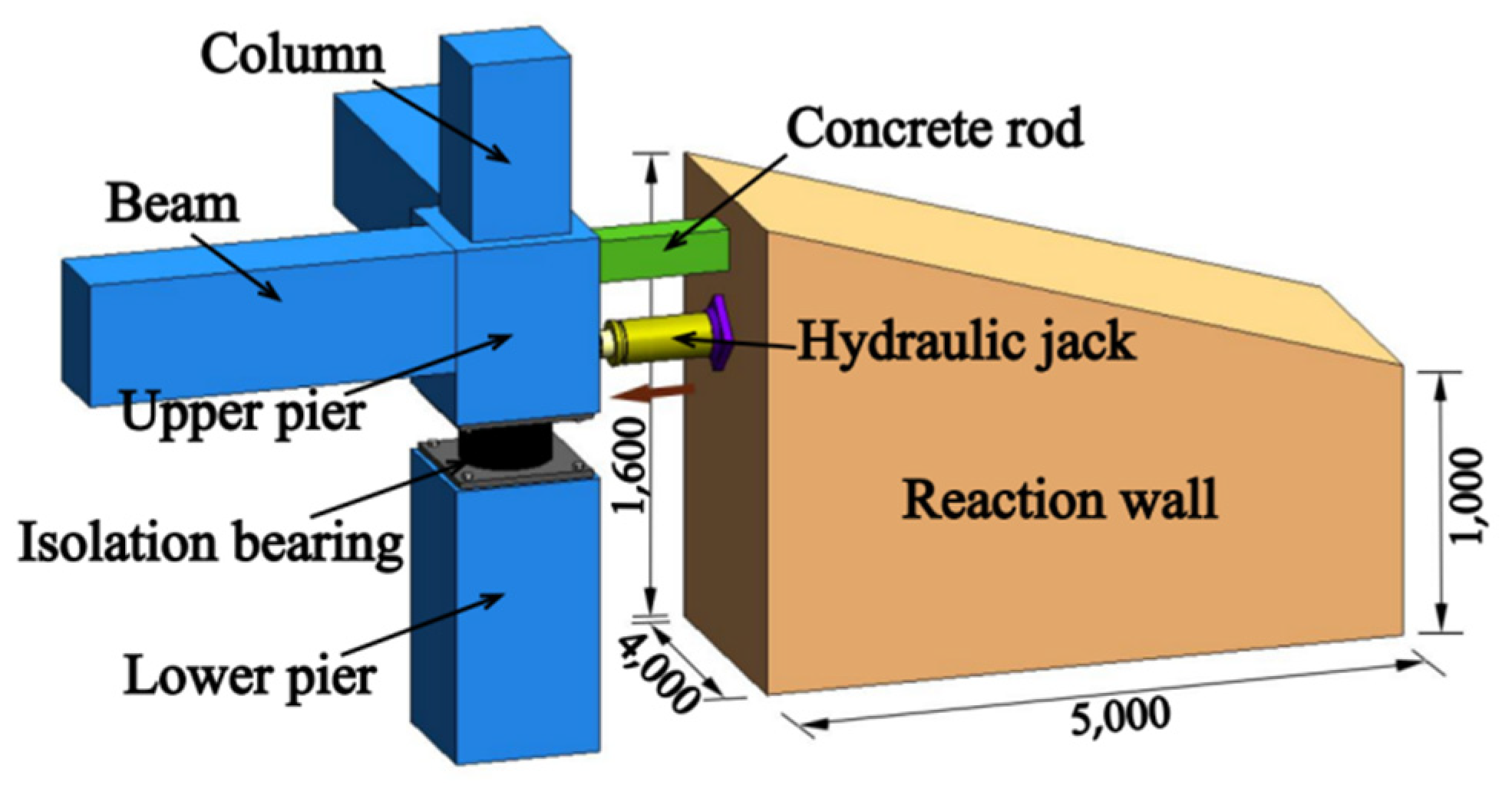
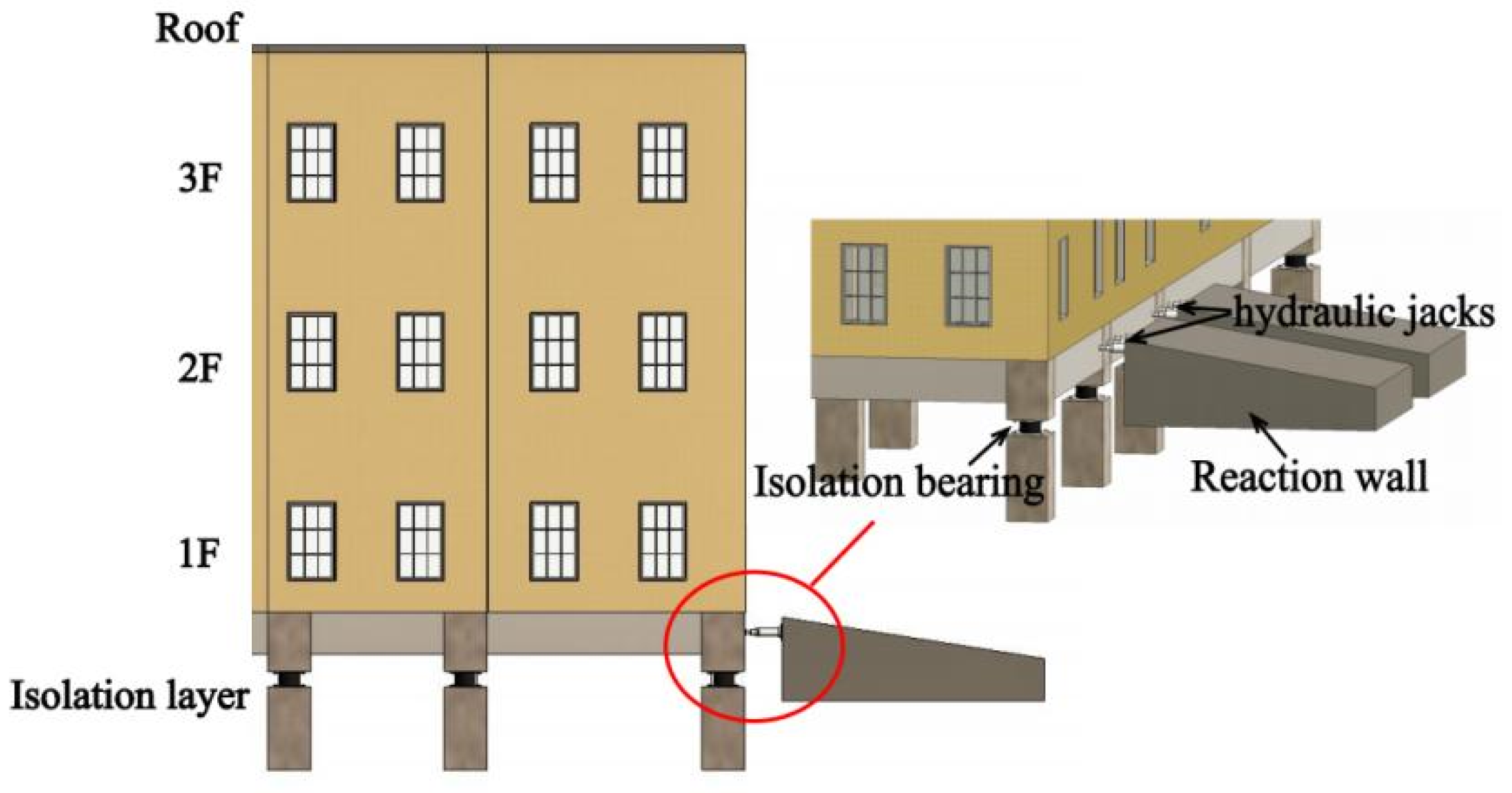
The horizontal displacement loading and unloading device is composed of concrete reaction walls, hydraulic jacks, and concrete rods.
The building measures 3586 m2 in total size and weighs 5586 tons in total weight. Without taking earthquake and live loads into account, the building’s true weight is approximately 3580 tons, or 1 ton/m2. As seen in Table 1, the preyield stiffness of LRB400 is 10.44 kN·mm−1, the yield force Qd of the isolation bearing is 45 kN, and the isolation layer is composed of 26 LRB400, resulting in a total preyield stiffness of 271.44 kN·mm−1, and a total yield shear of 1170 kN. Twenty unreinforced concrete rods with a diameter of 180 mm × 180 mm × 600 mm and a strength grade of C30 were poured in advance, and each concrete rod had an axial pressure of up to 463.32 kN (180 mm × 180 mm × 14.3 N·mm−1). Each reaction wall was constructed using four concrete rods for a total of sixteen rods, and the axial pressure can reach 7413.12 kN (463.32 kN × 16), which is significantly greater than the isolation layer shear of 1170 kN. Three holes, each 20 mm in diameter, are reserved for the concrete rod to be used to implant the emulsion explosive. To guarantee that the concrete rod remains in powder form following the explosion without generating shards that would obstruct the displacement of the isolation layer, two rods were tested prior to the test, with a total of 6 g of emulsion explosive in each hole.
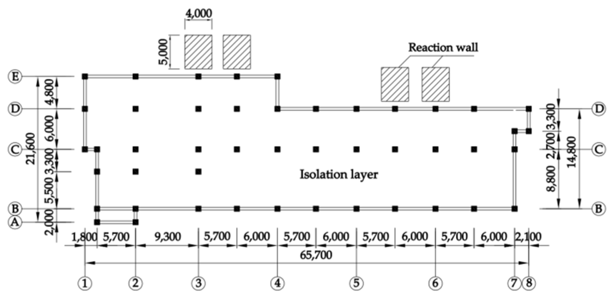
Given the building site’s suitable geological conditions and the relatively dense soil layer, four concrete reaction walls were poured in the north of the structure prior to the test. The construction of reaction wall requires less disturbance to the soil layer in order to obtain greater friction resistance. Calculations indicate that the concrete reaction wall is capable of withstanding the horizontal force required by the test. The reaction wall’s top surface is sloped, and the overall cross section is trapezoidal, allowing for the placement of the loading device without compromising the exterior floor height. The layout of the reaction wall considers the balance of the left and right moments of the structure’s center of mass, as illustrated in Figure 11. Figure 12 illustrates the schematic diagram of a test for loading and unloading the device.
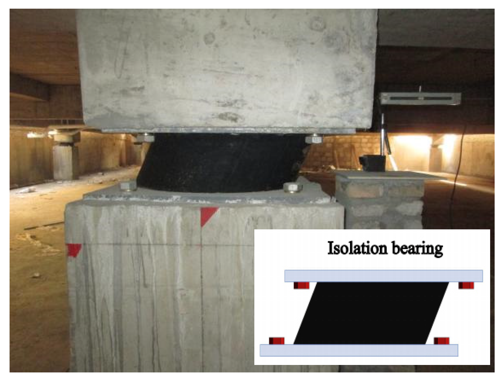
Twelve hydraulic jacks with a maximum load of 500 kN and a total output of 6000 kN were used in the test, with three hydraulic jacks on each reaction wall. The hydraulic jack is put against the reaction wall in advance of the test. Charging the hydraulic jack to induce gradual horizontal displacement of the upper structure. Figure 13 illustrates the schematic diagram used to apply the initial displacement. When the actual output of a single jack is 300 kN and the total output of 12 jacks is 3600 kN, it moves to the set displacement of 75 mm. At this point, the horizontal force applied to the building exceeds the yield force of the isolation layer by 1170 kN, indicating the lead core in the LRB has participated in the work [22]. Figure 14 illustrates the distorted isolation bearing.
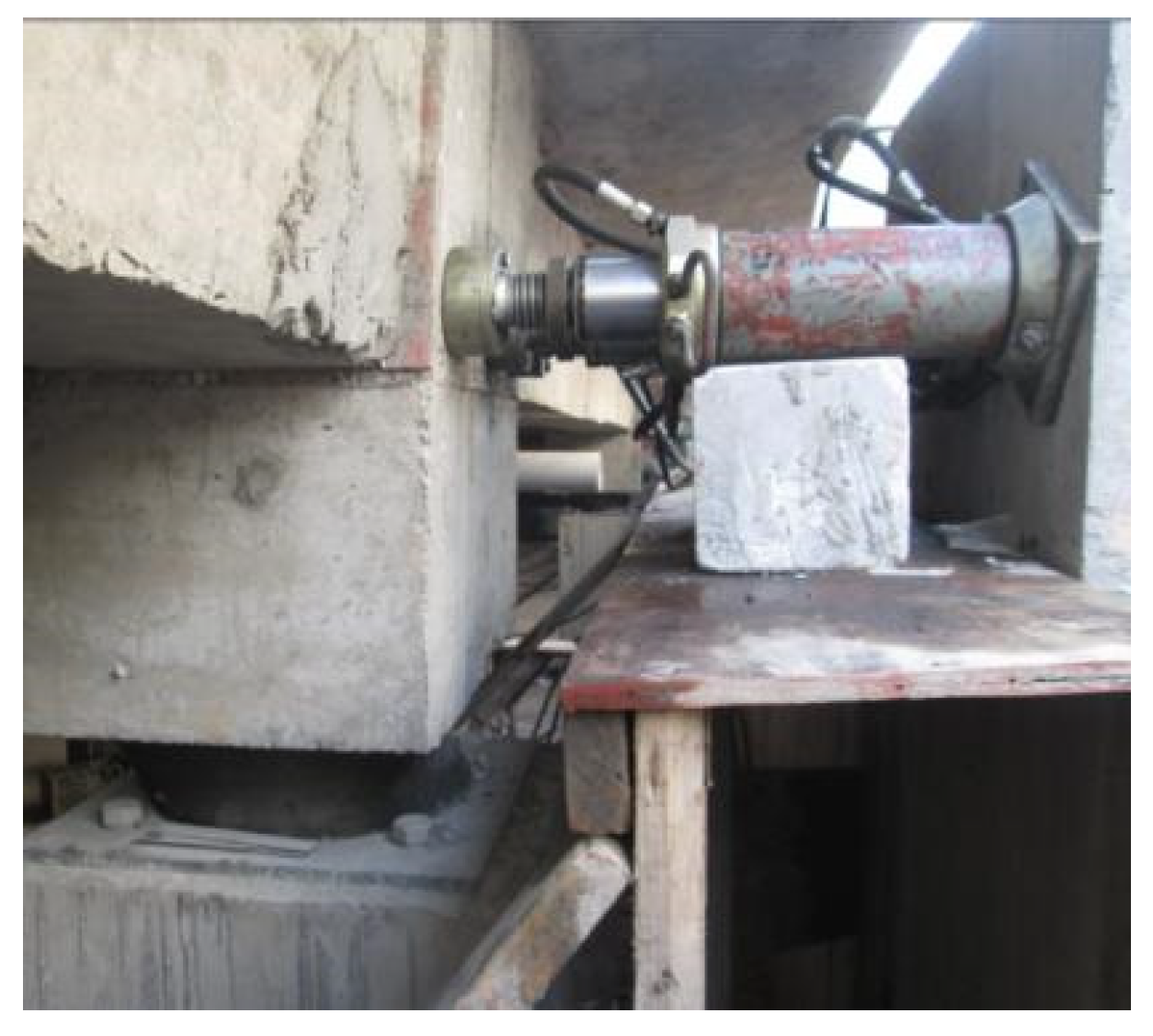
The concrete rod is positioned above the hydraulic jack, and both the hydraulic jack and the concrete rod are installed as close to the upper pier node as possible to guarantee the structure’s stress point is safe. After the hydraulic jack is unloaded, the concrete rod takes over, and the building with a predetermined initial displacement is completely supported by 16 concrete rods. Within the given time frame, the concrete rod is instantly damaged by explosive blasting and quits the job, leaving the superstructure vibration-free. At this point, the vibration signals are collected using sensors mounted on the east–west ends of each floor of the building to study the structure’s dynamic characteristics. The hydraulic jack’s operation is illustrated in Figure 15. In Figure 16, the concrete rods are fitted in place of the hydraulic jack, and the arrangement of the concrete rod blasting wire is illustrated.

3.4. Data Acquisition and Analysis

Prior to the transition test, the structure is subjected to ambient excitation in order to determine the structure’s first three natural vibration periods and the damping ratio of the structure [5]. Under the horizontal displacement, the DH612 sensor collects vibration signals before and after the instant of structural reset and connects them through cables to the computer’s dynamic data acquisition system. After amplification and filtering, the onsite dynamic vibration data is converted to digital signals using an A/D converter. The data file is obtained and imported into the modal analysis software, where it is processed using the fast Fourier transform (FFT). Spectrum analysis is used to determine the structure’s inherent vibration characteristics using the modal analysis method based on transmissivity [23,24]. A computational model of a seismic structure was constructed for comparison purposes.

3.5. Establishment of Structure Numerical Model

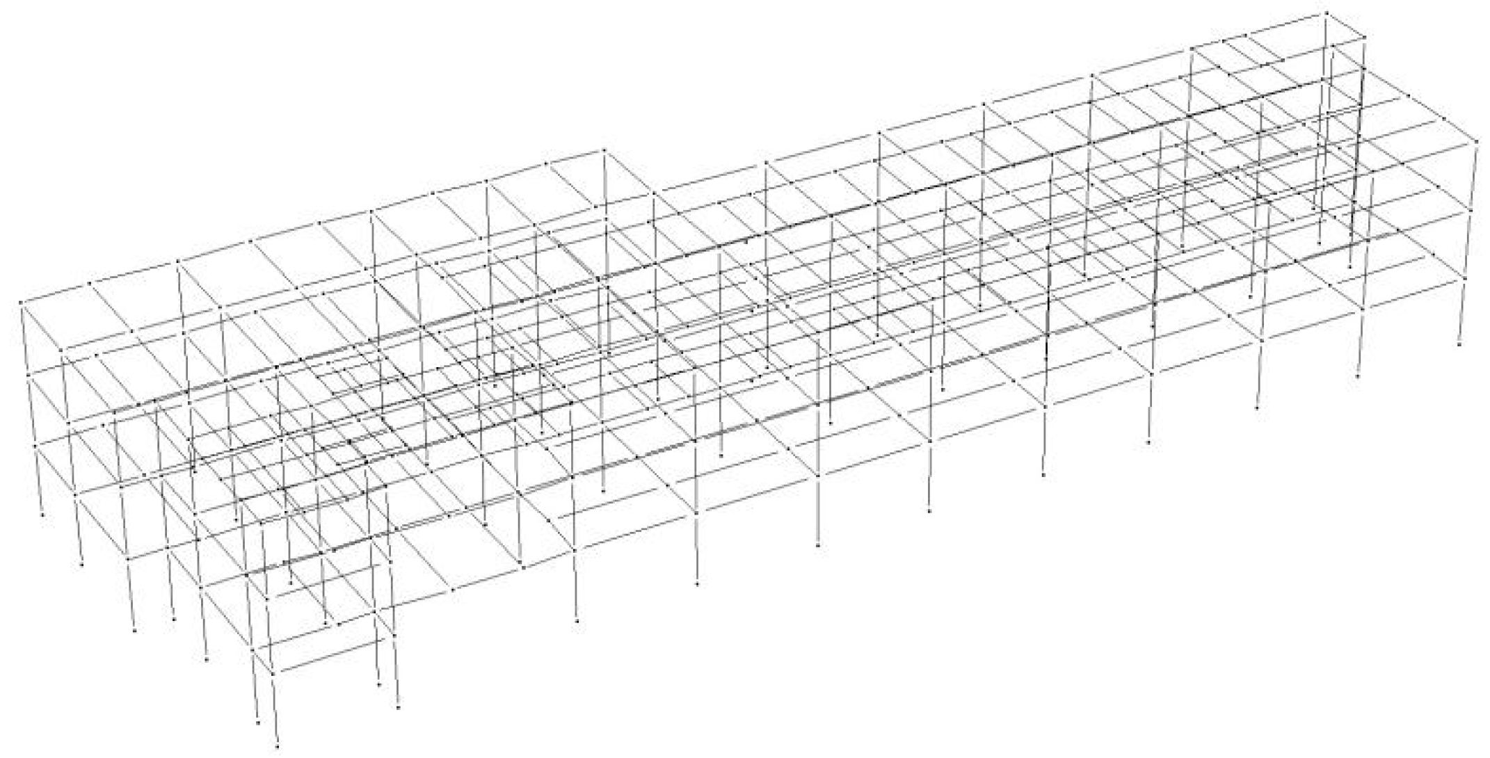
Previous studies have reported that the finite element analysis (FEA) using PERFORM-3D showed good calculation accuracy and efficiency [25], can better capture the yield situation, truly reflect the basic characteristics and nonlinear behavior of the structure, and has certain reliability [26]. Therefore, PERFORM-3D is used to simulate and analyze the structure due to the structure’s inelastic features.
The fiber model (“column, inelastic fiber section”) and the plastic hinge model (“moment hinge, curvature type”) are used as material models to represent the column’s and beam’s plastic zones, respectively. When a part achieves its maximum bearing capacity, the plastic hinge uses the moment curvature model to determine the yield stress, moment, and curvature. The column is constructed using three-dimensional fiber elements consisting of eight steel fiber elements and thirty-six concrete fiber elements, which is sufficient to yield a consistent stress-strain analysis finding. The following is a description of the modeling process:
(1) Simulation of a unit. Considering the calculation efficiency and analysis accuracy, the frame columns and beams are simulated by the fiber model and the concentrated plastic hinge model respectively. The plastic hinge utilizes the moment curvature model to determine the member yield and the corresponding moment and curvature when the beam section reaches its bearing capacity.
(2) Simulation of the constitutive connection of steel. The steel is Q235. The constitutive connection is based on the two broken line model considering follow-up hardening [27], and the stiffness ratio of steel after yield is taken as 0.01. The model can well describe the stress–strain relationship of steel and accurately simulate the mechanical properties of steel.
(3) Simulation of a concrete constitutive relationship. The concrete model is based on the Kent-Park model, which takes into account the deterioration of concrete’s hysteretic energy without taking into account the material’s tensile strength. The reason for omitting the tensile strength is that the additional mass of the floor slab is primarily simulated, and so has no effect on the simulation result. The compressive strength of the concrete is 20.1 MPa. The strength grade of the concrete is C30. After calibrating the material model parameters, they are entered into the finite element model.
By establishing two numerical models of isolated and seismic structures, we found that the bottom shear damping rate (i.e., the damping coefficient of Chinese code [15]) of isolated structure under moderate earthquake is 62%; Under severe earthquake, the damping rate of the floor acceleration is >60%, and that of the interlayer displacement is >65%. Except some columns at the bottom layer that are in elastic-plastic state, the rest of the superstructure are in elastic state, which fully shows that the isolated structure has good shock absorption capacity. The detailed comparison of the seismic responses of the two models is not discussed in detail bacause this study focuses on the structural dynamic characteristics of isolated structures during field tests.
Figure 17 illustrates the three-dimensional finite element model. The simulation results of seismic structure model are compared with the test results of horizontal initial displacement release, and the analysis results are discussed in Section 4.

4. Test Results and Analysis

4.1. Analysis of Results under Ambient Excitation

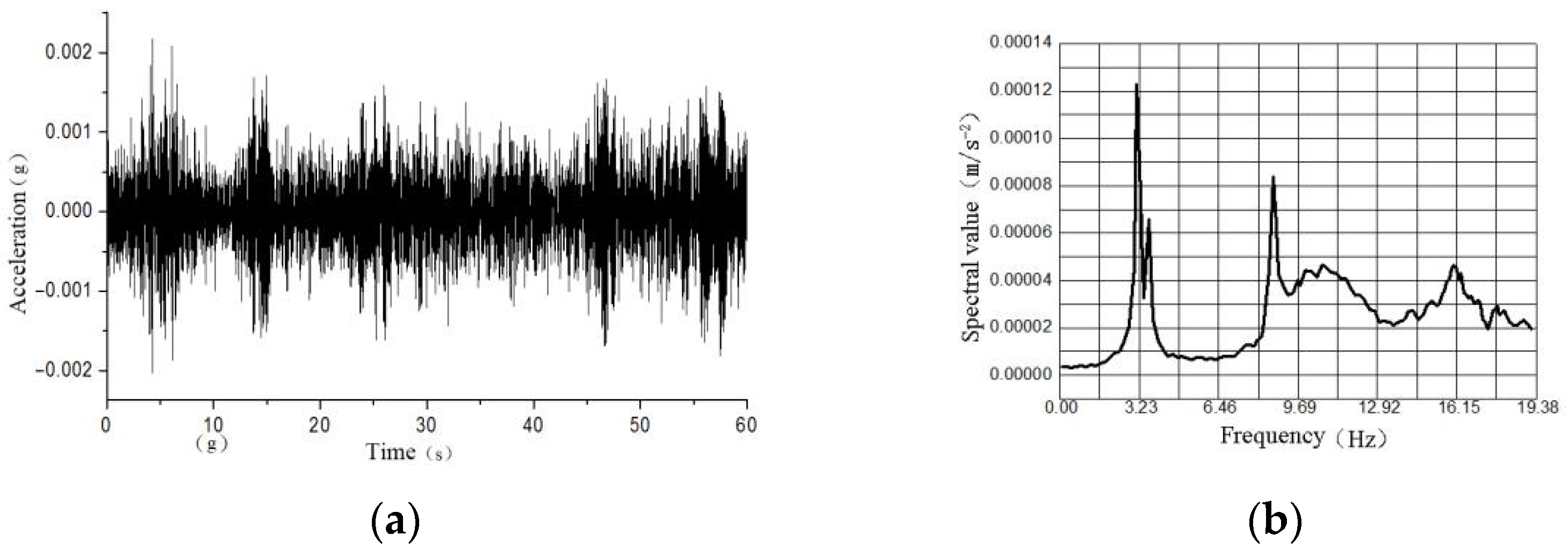
Prior to the initial displacement release test, the building is evaluated for environmental excitation. Acceleration sensors are used to capture signals generated by random vibrations. The sampling frequency is 200 Hz and the sampling time is 60 s, which meets the requirement for data smoothness [28,29]. Figure 18 illustrates the acceleration time-history curve in the Y direction and the corresponding spectrum.
DHMA modal analysis software is used to conduct modal analysis on acceleration signals in order to determine the structure’s inherent vibration characteristics. Figure 19 illustrates the structure’s first three vibration modes. We compared the first three natural vibration periods, damping ratios, and modes to the theoretical values for seismic structures under the same conditions. Table 3 summarizes the findings.
As illustrated in Table 3, the isolation structure’s self-vibration characteristics are similar to those of the seismic structure subjected to ambient excitation. While the natural vibration periods of the two structures are different, they both indicate the structure’s high rigidity. The isolation structure’s damping ratio is less than 5% of the seismic structure’s theoretical damping ratio (Chinese Code [15]). The isolation structure’s vibration modes are identical to those of the seismic structure, with the first and second modes involving horizontal movement and the third mode involving torsional movement. It can be deduced that the isolation structure is sufficiently stable in its serviceable (wind load and micro vibration). Additionally, it demonstrates that the seismic structure model’s design value is credible.

4.2. Test Results and Analysis of Horizontal Initial Displacement

4.2.1. Self-Vibration Characteristics of the Structure

Under the condition of a horizontal initial displacement of 75 mm, the measured data of each floor are modal analyzed to determine the structure’s fundamental period and damping ratio under the condition of a horizontal initial displacement of 75 mm. Given the possibility of measurement errors during the field test, the results from each measuring point are linearly weighted [30] and compared to the seismic model’s theoretical values using the FEA software PERFORM-3D. Table 4 contains the final results. Due to the Y-direction nature of the initial displacement release test, the natural vibration period and damping ratio obtained are the actual values corresponding to the structure’s first three Y-direction translational vibration modes.
As illustrated in Table 4, the isolation structure’s first-order natural vibration period is significantly longer than the seismic structure’s at 2.82 times (1.173/0.416), achieving the goal of extending the structure’s period; the damping ratio of the first-order mode is 22.39%, which is significantly greater than the seismic structure’s by 5%. It shows a good level of energy consumption and achieves the goal of minimizing horizontal earthquakes.

4.2.2. Floor Acceleration Response

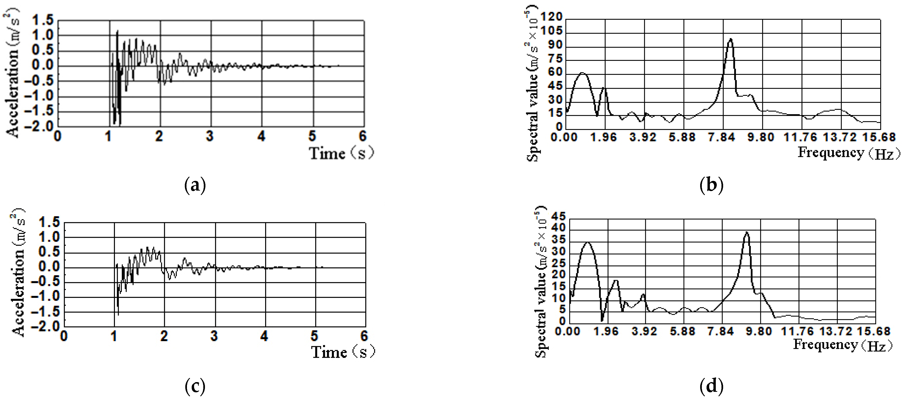
When the supporting ejector explodes, the structure attenuates vibration. Vibration signals are gathered using sensors situated on each floor, and dynamic signals are input into data gathering software to obtain acceleration attenuation curves for each floor, as well as spectrum characteristics. Since the acceleration attenuation fluctuates smoothly over three seconds and is nearly straight over four seconds, the acquisition time is set at six seconds, which accurately reflects the degree of attenuation. In the direction of travel, Figure 20 illustrates the free acceleration attenuation curves and the related frequency spectra for the first floor and the roof floor (Y direction).
To compare with the seismic structure and emphasize the isolation structure’s damping effect, the measured acceleration of the isolation structure’s first floor (154 gal) is input into the seismic structure’s first floor model for calculation. Thus, the acceleration response of each floor is determined and then compared to the acceleration response of the isolated structure to determine the floor’s associated seismic-reduction rate. The findings are summarized in Table 5. The seismic-reduction rate in Table 5 is equal to the following: (seismic model value—measured value of isolated structure)/seismic model value.
As illustrated in Table 5, the acceleration of the seismic structure increases with the rise of the floors, and the acceleration of the top floor is 2.28 times that of the bottom floor, which is consistent with the seismic structure law. However, the acceleration of the isolation structure increases slightly as the floor increases and generally exhibits horizontal movement characteristics, indicating that the seismic resiliency of the structure is intact, but the roof floor has a certain amplification effect, and its amplification factor is 1.27 (195 gal/154 gal).
It should be noted that the calculated seismic-reduction rate is low due to the fact that the force delivered during the test is located on the structure’s first floor, above the isolation layer. In comparison to the seismic wave input from the underground and transmitted to the superstructure via the isolation layer’s attenuation, the floor acceleration is not attenuated by the isolation layer, and the isolation structure’s response is large, but the isolation structure has good shock absorption effect (which can still be seen from the test data).

4.3. Reset Performance of Isolation Layer

When horizontal initial displacement is paired with dynamic data acquired by the displacement gauge, the isolation layer is promptly reset, with the reset amount equaling 62.86 mm, or 83.81% of the horizontal initial displacement value of 75 mm. With time, the isolation layer residual displacement is 12.14 mm, which gradually decreases to negligible after 48 h.

4.4. Hysteretic Curve of Isolation Layer

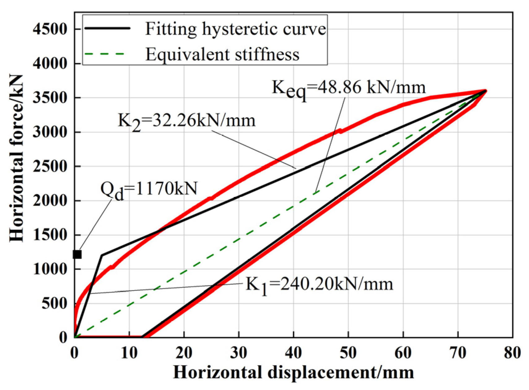
As all of the concrete rods’ blasting structure is released, it attenuates the vibration freely, allowing for the determination of the structure’s force-displacement relationship curve throughout horizontal movement and during the blasting to be obtained [31,32], as illustrated in Figure 21.
As illustrated in Figure 21, the falling slope of the curve is sharp at the point of blasting release, as the structure rapidly loses the horizontal support given by the concrete rods, in contrast to the leisurely unloading form of the hydraulic jack described in [12]. This technique’s unloading is more realistic, as the upper structure has already lost its horizontal support prior to being reset, and the reset time is unaffected by the hydraulic jack’s unloading time. Additionally, the study demonstrates that the isolation layer’s force-displacement relationship curve is a plump hysteretic loop, demonstrating its superior energy dissipation capacity. The hysteretic curve agrees with theoretical analytical [11].
It should be noted that since the time-history curve for structural reset is not gathered, the figure’s reset energy consumption curve is replaced by a straight line. Additionally, the isolation layer’s entire hysteretic curve reflects the lead bearing’s peculiar viscous elastic-plastic characteristics. The isolation layer’s capacity to absorb and consume seismic energy is mostly determined by the lead bearing.

5. Discussion and Suggestions

(1)
This paper presents a one-time and one-way horizontal push and release test on the building, which is not representative of the building’s reciprocating horizontal displacement during an earthquake. As a result, the parameters such as dynamic response obtained during the test are utilized as a benchmark for evaluating the performance of isolated structures.
(2)
The isolation layer can be reset almost instantly after the load is released. It can be inferred that when an earthquake occurs, the isolation layer will exhibit free attenuation movement and will promptly return to its initial position. This conclusion dispels any questions about the isolation bearing’s ability to be swiftly reset.
(3)
Edge and corner isolation bearings exhibit greater horizontal deformation than center bearings during the initial displacement. Therefore, while designing structural members, the displacement amplification factor of edge and corner isolation bearings should be considered, or the displacement of the least unfavorable isolation bearing should be used as the design value.
(4)
The building has been put into service, and the reserved reaction wall will be kept for later isolation structure tests, as well as the natural aging and degradation performance of the isolation bearing.

6. Conclusions

(1)
The natural vibration characteristics of isolated and seismic structure are similar in the presence of environmental excitation. Under regular use conditions, the isolated structure is sufficiently stable, which is consistent with the research conclusions of relevant literature.
(2)
Under the condition of 75 mm horizontal initial displacement, the isolated structure’s natural vibration period is significantly longer than that of the seismic structure, and the first-order period ratio is 2.82 times, indicating that the isolation layer achieves the goal of prolonging the isolated structural period. The damping ratio of the first order is 22.39%, indicating that the isolation layer has achieved the goal of further reducing the horizontal seismic action.
(3)
The acceleration of an isolated structure increases slightly as the floor height increases, and it typically exhibits translational motion characteristics. This demonstrates that the isolation structure has an excellent level of control over each floor’s seismic reaction, and the acceleration dampening effect is rather impressive. However, the roof layer has an amplification effect, and its amplification value of 1.27 is noteworthy.
(4)
After releasing horizontal initial displacement, the isolation layer is basically instantaneously reset, indicating that the isolation layer has a high degree of reset performance.
(5)
The horizontal initial displacement test shows that the isolation layer’s force-displacement relationship curve is a plump hysteretic loop, demonstrating its superior energy dissipation capacity.

Author Contributions

Conceptualization, Y.-X.W., Y.-Q.L., and H.-D.C.; methodology, Y.-X.W., X.-J.D. and Y.-Q.L.; software, X.-J.D. and Y.-Q.L.; validation, Y.-X.W. and H.-D.C.; formal analysis, Y.-X.W. and X.-J.D.; investigation, Y.-X.W., X.-J.D. and H.-D.C.; resources, Y.-X.W. and Y.-Q.L.; data curation, Y.-X.W. and X.-J.D.; writing—original draft preparation, Y.-X.W. and X.-J.D.; writing—review and editing, Y.-X.W., X.-J.D. and Y.-Q.L.; visualization, X.-J.D.; supervision, Y.-Q.L.; project administration, Y.-X.W. and H.-D.C.; funding acquisition, Y.-X.W. All authors have read and agreed to the published version of the manuscript.

Funding

This research was funded by the National Natural Science Foundation of China, Grant No. 51778149), and Xiamen Construction Science and technology planning project (2014) No. 21, Fujian Province, China.

Institutional Review Board Statement

Not applicable.

Informed Consent Statement

Not applicable.

Data Availability Statement

Not applicable.

Conflicts of Interest

The authors declare no conflict of interest.

References

  1. Nagarajaiah, S.; Sun, X.H. Seismic perfomance od base isolated buildings in the 1994 northridge earthquake. In Proceedings of the 11th World Conference on Earthquake Engineering, Acapulco, Mexico, 1–6 August 1996; Paper No. 598; Pergamon: Oxford, UK, 1996. [Google Scholar]
  2. Naeim, F.; Kelly, J.M. Design of Seismic Isolation Structure: From Theory to Practice; John Wiley & Sons: Hoboken, NJ, USA, 1999. [Google Scholar]
  3. Fu, J.H. Design Method for Seismic and Isolation Structures in Japan; China Architecture & Building Press: Beijing, China, 2011. [Google Scholar]
  4. The Japan Society of Seicmic Isolation. Introduction to Isolation Structures; Ohmsha Press: Tokyo, Japan, 1995. [Google Scholar]
  5. Han, J.P.; Wang, H.T.; Liu, Y.S.; Du, Y.F.; Li, H. Investigation on main dynamic characteristics of base-isolated structures under ambient excitation. J. Vib. Shock 2011, 30, 266–271. [Google Scholar]
  6. Architectural Institute of Japan. Structural Design Concepts for Seismically Isolated Buildings against Extreme Ground Motions; Architectural Institute of Japan: Tokyo, Japan, 2020. [Google Scholar]
  7. Liu, W.D.; Lan, Z.J.; Liu, W.Q.; Liu, D.P. Vibration test of a high-rise building and seismic performance analysis. World Inform. Earthq. Eng. 2010, 26, 169–174. [Google Scholar]
  8. Bettinali, F.; Forni, M.; Indirli, M. In-situ dynamic tests of a large seismically isolated building. In Proceedings of the Interntional Meeting on Earthquake Protection of Buildings, Ancona, Italy, 22 April 1991. [Google Scholar]
  9. Forni, M.; Martelli, A.; Spadoni, B. Dynamic tests on seismically isolated structure mock-ups and validation of numerical models. In Proceedings of the International Meeting on Earthquake Protection of Buildings, Ancona, Italy, 22 April 1991. [Google Scholar]
  10. Braga, F.; Laterza, M.; Gigliotti, R. Seismic isolation using slide and rubber bearings: Large amplitude free vibration tests on the Rapolla residence building. In Proceedings of the 7th International Seminar on Seismic Isolation, Assisi, Italy, 2–5 October 2001; Passive Energy Dissipation and Active Control of Vibrations of Structures: Assisi, Italy, 2001; pp. 121–152. [Google Scholar]
  11. Bixio, A.R.; Dolce, M.; Nigro, D.; Ponzo, F.C.; Braga, F.; Ncoletti, M. Repeatable dynamic release tests on a base-isolated building. J. Earthq. Eng. 2001, 5, 369–393. [Google Scholar] [CrossRef]
  12. Braga, F.; Laterza, M. Field testing of low-rise base isolated building. Eng. Struct. 2004, 26, 1599–1610. [Google Scholar] [CrossRef]
  13. Wei, L.S.; Zhou, F.L.; Chen, J.Q.; Ren, M.; Xia, C. Study on test of dynamic characteristics for avibration isolation building. J. Vib. Shock 2007, 26, 150–152. [Google Scholar]
  14. He, Y.M. Dynamic Field Test for A Base-Isolated High-Rise Steel Building Structure. Master’s Thesis, Institute of Engineering Mechanics, China Earthquake Administration, Harbin, China, June 2013. [Google Scholar]
  15. GB 50011-2010. Code for Seismic Design of Buildings; China Architecture & Building Press: Beijing, China, 2016. [Google Scholar]
  16. Pianese, G.; Milani, G.; Cerchiaro, R.; Milani, F. Optimal vulcanization of unbonded fiber reinforced elastomeric isolator devices. Chem. Eng. Trans. 2021, 86, 1321–1326. [Google Scholar]
  17. Milani, G.; Milani, F. Optimal vulcanization of tires: Experimentation on idealized NRPB natural and poly-butadiene rubber blends, phenomenological smoothed numerical kinetic model and FE implementation. Polym. Test. 2018, 72, 63–85. [Google Scholar] [CrossRef]
  18. Zhou, Y.; Zhang, J.C.; Tang, Y.G.; Deng, X.S. Analysis of optimal placement of rubber isolated bearins in District E of the Guangdong Science Center. Earthq. Eng. Eng. Dyn. 2009, 29, 183–191. [Google Scholar]
  19. Chieffo, N.; Mosoarca, M.; Formisano, A.; Lourenço, P.B.; Milani, G. The effect of ground motion vertical component on the seismic response of historical masonry buildings: The case study of the Banloc Castle in Romania. Eng. Struct. 2021, 249, 113346. [Google Scholar] [CrossRef]
  20. GB 20688.3-2006. Rubber Bearings-Part 3: Elastomeric Seismic-Protection Isolators for Buildings; Standards Press of China: Beijing, China, 2006. [Google Scholar]
  21. Li, T.; Pan, Y.X.; Tong, K.T.; Ventura, C.E.; de Silva, C.W. A multi-scale attention neural network for sensor location selection and nonlinear structural seismic response prediction. Comput. Struct. 2021, 248, 106507. [Google Scholar] [CrossRef]
  22. Robinson, W.H. Lead-rubber hysteretic bearing suitable for protecting structures during earthquake. Earthq. Eng. Struct. Dyn. 1982, 10, 359–604. [Google Scholar] [CrossRef]
  23. Derivendt, C.; Guillaume, P. Operational modal analysis in the presence of unknown arbitrary loads using transmissibility measurements. In Proceedings of the 13th International Congress on Sound and Vibration, Viennal, Austria, 2–6 July 2006; International Institute of Acoustics and Vibrations: Auburn, AL, USA, 2006. [Google Scholar]
  24. Li, X.Z.; Yue, X.B.; Huang, W.; Dong, X.J.; Peng, J.K. Vibration response transmissibility and operationalmodal analysis methods: A review and comparative study. J. Vib. Shock 2019, 38, 24–34. [Google Scholar]
  25. Xie, L.L.; Lu, X.Z.; Guan, H. Experimental study and numerical model calibration for earthquake-induced collapse of RC frames with emphasis on key columns, joints and the overall structure. J. Earthq. Eng. 2015, 19, 1320–1344. [Google Scholar] [CrossRef]
  26. Al Mamuna, A.; Saatcioglu, M. Analytical modeling of moderately ductile RC frame structures for seismic performance evaluation using PERFORM-3D. Earthq. Spectr. 2019, 35, 635–652. [Google Scholar] [CrossRef]
  27. Computer and Structures, Inc. PERFORM-3D Nonlinear Analysis and Performance Assessment for 3D Structures USER GUIDE, 4rd ed.; University of California: Berkeley, CA, USA, 2006. [Google Scholar]
  28. The Japan Society of Seismic Isolation. Guidelines for the Wind-resistant Design of Seismically Based-isolated Buildings; The Japan Society of Seismic Isolation: Tokyo, Japan, 2012. [Google Scholar]
  29. Ventura, C.E.; Finn, W.D.L.; Lord, J.F.; Fujita, N. Dynamic characteristics of a base isolated building from ambient vibration measurements and low level earthquake shaking. Soil Dyn. Earthq. Eng. 2003, 23, 313–322. [Google Scholar] [CrossRef]
  30. Wang, J.; Zheng, D.C.; Zhang, J.C.; Zhan, X.Y.; Qian, T. Seismic velocity changes in the eqicentral region of the 2013 Lushan earthquake measured from ambient seismic noise. Chin. J. Geophys. 2020, 63, 517–531. [Google Scholar]
  31. Takeuchi, T.; Wada, A. Buckling-Restrained Braces and Applications; The Japan Society of Seismic Isolation: Tokyo, Japan, 2017. [Google Scholar]
  32. The Japan Society of Seismic Isolation. Design Guidelines for Joints of Base Isolated Members, 3rd ed.; The Japan Society of Seismic Isolation: Tokyo, Japan, 2020. [Google Scholar]
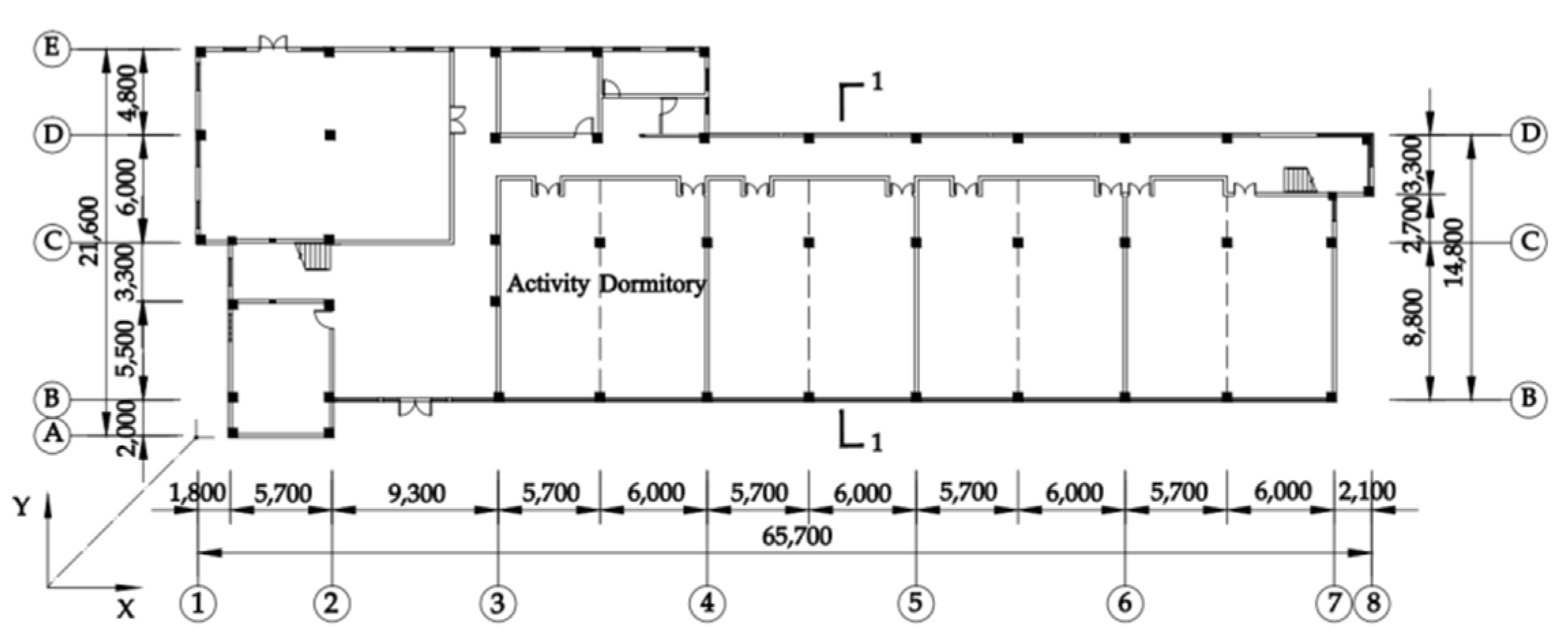
Figure 1. Ground floor plan (Unit: mm).
Applsci 12 00232 g001
Figure 2. Profile 1-1 (Unit: mm).
Applsci 12 00232 g002
Figure 3. Elevation of the building.
Applsci 12 00232 g003
Figure 4. Isolation overhaul layer.
Applsci 12 00232 g004
Figure 5. Layout plan of isolation bearing (Unit: mm).
Applsci 12 00232 g005
Figure 6. Construction and installation of isolation bearing.
Applsci 12 00232 g006
Figure 7. Loading test machine.
Applsci 12 00232 g007
Figure 8. The hysteretic curve of isolation bearing: (a) LRB400; (b) LNR500.
Applsci 12 00232 g008
Figure 9. Field testing instruments and related equipments: (a) DH612 sensor; (b) electric displacement meter; (c) data acquisition instrument.
Applsci 12 00232 g009
Figure 10. Sensors configuration: (a) field layout of sensors; (b) floor layout of sensors.
Applsci 12 00232 g010
Figure 11. Reaction wall layout plan (unit: mm).
Applsci 12 00232 g011
Figure 12. Schematic diagram of a test loading and unloading device (unit: mm).
Applsci 12 00232 g012
Figure 13. Schematic diagram of initial displacement application.
Applsci 12 00232 g013
Figure 14. Distorted isolation bearing.
Applsci 12 00232 g014
Figure 15. Schematic diagram of hydraulic jack.
Applsci 12 00232 g015
Figure 16. Schematic diagram of concrete rods.
Applsci 12 00232 g016
Figure 17. Finite element model of seismic structure.
Applsci 12 00232 g017
Figure 18. (a)Acceleration time-history curve (Y direction); (b) The corresponding spectrum.
Applsci 12 00232 g018
Figure 19. Vibration modes of structures of different order: (a) first order mode; (b) second order mode; (c) third order mode.
Applsci 12 00232 g019
Figure 20. Acceleration attenuation curve and the related spectrum: (a) acceleration attenuation curve (roof floor); (b) spectrum (roof floor); (c) acceleration attenuation curve (first floor); (d) spectrum (first floor).
Applsci 12 00232 g020
Figure 21. Hysteretic curve of isolation layer.
Applsci 12 00232 g021
Table 1. Specifications and mechanical characteristics of isolation bearings.
Bearing TypeTotal Thickness of Internal Rubber Layer/mmPre-Yield Stiffness/kN·mm−1Post-Yield Stiffness Kd/kN·mm−1Horizontal Equivalent Stiffness Kh/kN·mm−1Equivalent Damping RatioYield Force Qd/kN
γ = 100%γ = 250%γ = 100%γ = 250%γ = 100%γ = 250%
LRB 40068.6010.440.8700.6991.4351.0190.260.1845
LNR 50096///0.9370.8900.050.05/
Table 2. Sensor numbers for each floor.
Sensor TypeFloor Location
1st Floor Westward2nd Floor Westward3rd Floor WestwardRoof Floor Westward1st Floor Eastward2nd Floor Eastward3rd Floor EastwardRoof Floor Eastward
Speed sensorV1V2V3V4V5V6V7V8
Acceleration sensorA1A2A3A4A5A6A7A8
Table 3. Analysis results of natural vibration characteristics.
Mode OrderNatural Vibration Period/sDamping Ratio/%Mode Description
Isolation StructureSeismic StructureIsolation StructureSeismic StructureIsolation StructureSeismic Structure
First order0.3200.4162.995.00horizontal movementhorizontal movement
Second order0.3110.4082.085.00horizontal movementhorizontal movement
Third order0.2880.3822.125.00torsional movementtorsional movement
Table 4. Comparison of analysis results of first three-order self-vibration characteristics of structure.
Mode OrderNatural Vibration Period/sDamping Ratio/%
Seismic StructureHorizontal MovementSeismic StructureHorizontal Movement
First order0.4161.1735.0022.39
Second order0.2210.3865.0010.86
Third order0.1150.1765.003.72
Table 5. Structural acceleration and seismic-reduction rate.
FloorSeismic Structure/galIsolation Structure/galSeismic-Reduction Rate/%
Roof floor35119545.80
325417331.89
220716918.36
1154154/
Publisher’s Note: MDPI stays neutral with regard to jurisdictional claims in published maps and institutional affiliations.