1. Introduction
Gears represent the most important design elements in drive technology for transmitting speed and torque. The global market for gears, drives and speed converters is expected to continue its strong growth in the future, from a revenue of USD 153.7 billion (2020) up to USD 192.7 billion in 2026 [
1]. The demand is particularly high for gears in the low and medium power range, which are used for example in the automotive industry in steering systems, window regulators, seat adjustment and air conditioning systems [
2] as well as for automation solutions or in medical technology [
3]. For these applications, the metal-polymer material combination, which is suitable for actuators and gearboxes with medium power requirements [
4] offers great potential [
5]. The material pairing has advantages over pure metal or polymer pairings due to its reduced weight, beneficial damping properties and the ability to be operated in dry running without lubrication [
6].
Conventionally, cutting processes are used to produce metallic gears. However, forming processes, such as cold forging offer great potential due to short cycle times, high productivity and material utilization, as well as improved component properties with regard to tooth flank hardness and surface quality [
7]. Metallic gears for the material pairing metal-polymer can be produced ready-to-use by cold forging with sufficient accuracy in a highly productive and resource efficient process [
8]. In addition to steel, aluminum offers potential as a metallic material due to its low density and cold formability [
8].
During operation of gear pairs of the material combination, the occurring wear limits the lifetime and compliance of the functionally relevant tolerances [
9]. Previous studies determined the influence of the mechanical component properties and the surface topography of the metal gear [
10]. Hardness [
11] and roughness [
12] are of importance. In addition, model tests have identified the load resulting from surface pressure and sliding velocity as influencing variables [
13]. Insufficient knowledge exists about the influence of tooth geometry on the wear behavior.
In order to enable gear production by extrusion, it is necessary to adapt the involute tooth geometry by adding gear radii [
14]. The gear radii have a significant influence on the extrusion process and the achievable component properties. From the perspective of the forming process, large radii are advantageous [
15]. Reasons for this are a more homogeneous material flow and reduced die stress. The influence of gear radii on wear within the metal-polymer material pairing has not yet been investigated, and the effects of modified gear radii are not known. In previous studies on the effects of contact behavior on wear, it was shown that the specific sliding within the gear pair has an influence on wear and that the wear occurring locally on the tooth could be reduced by adapting the tooth profile [
16]. The influence of gear radii has only been investigated regarding the load carrying capacity of polymer gears, but not on wear. It has been shown that increased radii reduce stresses in the tooth root and increase the load carrying capacity [
17].
Against the background of the use of extrusion for the production of metallic gears for the material pairing, the application of preferably large gear radii is required. Since the length of the active tooth flank is changed by the gear radii, an influence on the load situation and wear is also to be expected. In order to enable a design of metallic gears that meets the requirements with regard to manufacturing and operational behavior, it is necessary to investigate the influence of the gear radii on wear.
2. Objective and Methodology
The objective of this study is to determine the influence of the metallic pinion tooth geometry on the wear behavior of a metal-polyamide material pairing and to generate generally applicable findings from the results, which can be transferred to other metallic gear materials and gear geometries. For this purpose, it is necessary to determine the effect of an adjusted tooth geometry on the contact behavior of the gear pair and the load of the gear flank. Furthermore, the influence of the changed load situation on the wear behavior of the pinion and wheel must be investigated, and the transferability of the findings to other metallic materials within the material pairing must be examined.
Initially, the influence of the contact behavior of the gear pair on the local load and wear of the tooth flank is determined. Subsequently, the impact of the tooth radii on the length of the active flank, the resulting path of contact and the local load of the tooth flanks is evaluated. Metallic pinions are manufactured with varying gear radii in order to purposely influence the occurring load within the gear pair and the wear behavior is investigated on a gear test rig. The wear occurring locally on the tooth flank and the alteration of the surface topography are characterized. Finally, functional relationships between the choice of gear radii, the load situation and the wear behavior are derived and the transferability of the findings to a metal gear material with increased hardness is investigated.
3. Experimental Procedure
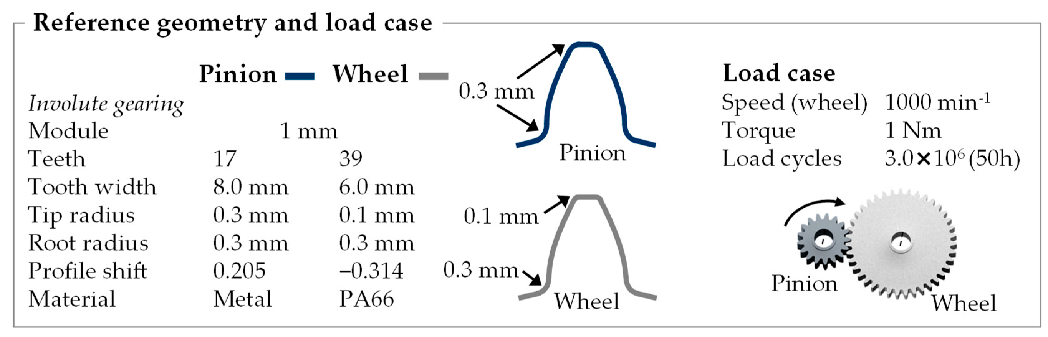
Initially, the investigated gear pair, materials and the experimental procedure are described (
Figure 1). The investigations are carried out on a single-stage gear pair consisting of a metal pinion and a polymer wheel.
The gearing has an involute tooth profile with a module of 1 mm. The pinion has 17 teeth and the wheel 39 teeth, which is a typical gear size for actuators [
18]. In order to prevent undercut of the pinion and enable manufacturing by extrusion, the pinion is designed with a positive profile shift as well as tip and root radii of 0.3 mm, which were determined in a previous study [
15]. A negative profile shift has been added to the wheel to achieve a total profile shift of zero and an unchanged center distance of 28.00 mm. The pinion is loaded with a torque of 1 Nm. The speeds of the pinion and wheel are 2294 min
−1 and 1000 min
−1. This results in an output of 240 W, which corresponds to gear drives in the medium power range [
5].
Within this investigation, the metallic gears are manufactured by electrical discharge machining (EDM) to achieve reproducible geometric and mechanical component properties, despite variation of the tooth geometry. The obtainable geometrical accuracy is comparable to that of extruded gears. However, in contrast to extrusion, in the EDM process, the tooth geometry does not affect the achievable accuracy and mechanical component properties, which is necessary to ensure a targeted investigation of the effects of the tooth geometry on the wear behavior. The surface of the metallic pinions was sandblasted (grain size 10–20 µm), in order to achieve a homogeneous surface topography at the beginning of the wear tests of approximately SZ 6 µm (maximum profile height).
3.1. Gear Materials
The use of light metals within the metal-polymer material pairing offers great potential due to the possibility of weight savings compared to steel, which represents the industrial standard [
4]. With regard to the application of cold forging, aluminum, as well as low-alloy steels, offer good cold formability. The aluminum material AlMgSi1 in T6 temper (annealed and artificially aged) with a hardness of 120 HV is used for the investigation. In order to test the transferability of the findings to metallic materials with higher strength, the steel material 16MnCr5 with a hardness of 450 HV is also investigated.
The wheel is made of Ultramid A3K polyamide 66 (PA66), which is an industrially relevant gear material [
4]. The polymer gears were manufactured by injection molding on an Arburg 70U 700 30 30 (Arburg GmbH Co KG) by the Institute of Polymer Technology (LKT) at the Friedrich-Alexander Universität Erlangen-Nürnberg and provided for the study.
3.2. Evaluation of Wear Behavior
The wear behavior of the gear pair is examined on a gear test rig set up in accordance with the recommendations of VDI Guideline 2736, Sheet 4, which is shown in
Figure 2 [
18]. A total of six load cycles with a duration of 8.3 h each are performed. This corresponds to 3.0 × 10
6 revolutions (500,000 revolutions per load cycle) on the polymer gear at the output speed of 1000 min
−1. The wear-related change in the geometry of the wheel and pinion is measured on a coordinate measuring machine (Hexagon Metrology GmbH) after each load cycle, and the wear volume is determined from a measurement of the cross section. In addition, the tooth flank topography of the metal pinion is recorded with a confocal laser scanning microscope (Keyence Corporation) in order to draw conclusions about the occurring wear mechanisms from the change of surface topography.
3.3. Wear Behavior of the Reference Pairing
The wear behavior of the gear pair with the reference geometry and an aluminum pinion is shown below.
Figure 3 shows the volumetric wear occurring within the pairing and the change of the tooth flank topography of the metal pinion during the wear test.
Wear occurs on both the metal pinion and the polymer wheel, which leads to a reduction in tooth thickness and is critical for failure if it progresses [
18]. A characteristic wear behavior of the pairing with a running-in phase and the beginning of a stationary wear phase is shown (
Figure 3a). Within the first 0.5 × 10
6 load cycles (8.3 h), high wear occurs on both gears, reducing the tooth volume by a total of 372.8 ± 17.3 µm
3. As the number of load cycles increases, the wear rate decreases, and the wear behavior enters a steady-state, while the surface topographies of the friction partners converge. In the stationary phase, the wear rate is largely constant. A total wear volume of 1000.9 ± 47.3 µm
3 resulting from 137.9 ± 14.5 µm
3 wear on the metal pinion and 863.0 ± 32.8 µm
3 on the polymer wheel occurs (
Figure 3a).
The surface topography of the tooth flank of the metallic pinion (
Figure 3b) shows the influence of the load cycles on the roughness. Due to the stress, the surface topography of the metal pinion is heavily roughened and the metal tooth flank is subject to wear. The surface topography remains largely constant after the running-in phase (approx. 0.5 × 10
6) and exhibits a high roughness of S
Z 12.52 ± 2.29 µm. The roughness of the metallic tooth flank and the released metallic particles facilitate abrasive wear of the polymer gear.
4. Evaluation of Local Load and Wear
In the following, the influence of the tooth geometry on the contact behavior, the resulting load and wear of the tooth flank is investigated. First, the contact behavior of the gearing is determined and the resulting load of the tooth flank is evaluated.
4.1. Contact Behavior
Depending on the tooth geometry, the contact behavior results in an overlap of two or only one tooth pairs that are in mesh at the same time.
Figure 4 shows the contact behavior of an involute gear pair without tip and root radii and the resulting path of contact of tooth 1.
At the point of contact A of tooth 1, the adjacent tooth 17 is still in contact (two tooth pairs in mesh). The two tooth pairs are in mesh simultaneously up to the point of contact B. At this point, tooth 17 of the pinion is in contact with the tooth tip of the wheel and loses the contact when the pairing is rotating further. From this point on, tooth pair 1 is alone in contact, and there is no overlap with other teeth (one tooth pair in mesh). This results in a high line load on tooth 1. At pitch point C, there is ideal rolling, and the relative sliding speed of the gear and pinion is zero. With further rotation to the point of contact D of tooth 1, the next tooth (2) of the pinion comes into contact with the tip of the wheel. Due to the overlapping of tooth pairs 1 and 2 (two tooth pairs in mesh), the line load of the single teeth is reduced again. The point of contact E of tooth 1 corresponds to the point of contact B of tooth 2.
4.2. Local Load of the Tooth Flank
The movement of the contact point along the tooth flank results in a varying sliding velocity and line load due to the changed leverage effect from tooth root to tooth tip. In addition, the overlap of one or two tooth pairs results in a doubling or halving of the line load, which leads to varying load on the tooth flank. The resulting load is described by the combination of the sliding velocity of the tooth flanks and the applied torque.
The acting line load
is calculated from the torque
, the diameter
and the tooth width
[
19]. The line load does not take elastic behavior in the contact area into account. However, it is known from other investigations that the surface pressure resulting from tooth deformation is of secondary importance for tribological considerations of wear [
20].
Figure 5 shows the points of contact resulting from the contact behavior and the acting line load along the tooth flank (
Figure 4). When two tooth pairs are in mesh (contact points A to B and D to E), the line load is halved compared to areas with overlap of only one tooth pair (contact points B to D). The line load is reduced from a maximum amount of 20.6 N/mm (one tooth pair in mesh) to 10.3 N/mm (two tooth pairs in mesh). The load decreases in the direction of the tooth tip due to the leverage effect of the increasing diameter.
In the next step, the sliding stress is evaluated. The sliding stress results from a relative speed of the two tooth flanks due to different tangential speeds. Therefore, the local velocities of the tooth flanks of the pinion and wheel must be taken into account. The peripheral velocity of pinion (1) and wheel (2) are each derived from the rotational speed
and the gear diameter
[
19].
Using the peripheral velocity and the pressure angle
, the local tangential velocity
along the path of contact
is calculated [
19].
The sliding velocities
of the pinion and
of the wheel along the position
on the path of contact are calculated from the difference of both tangential velocities [
19].
The stress resulting from sliding is described by the specific sliding
, which is calculated from the ratio of the sliding velocity to the radial velocity [
19].
Figure 6a shows the tangential velocities along the tooth flank and the resulting sliding stress by means of the specific sliding. The tangential velocity increases along the tooth flank toward the tooth tip due to the increasing diameter.
The lowest speed is therefore at the tooth root (contact points A or E) and the highest at the tooth tip (E or A). In the pitch point (contact point C), the speed of both gears is identical (ideal rolling). In the tooth root and tooth tip area, however, the tangential velocities are different and sliding occurs. The sliding stress can be expressed by the specific sliding (
Figure 6b). The specific sliding increases with distance from the pitch point (C) due to the increasing relative speed of both gears. The highest specific sliding occurs at the root of the tooth, since here a small flank section (low speed) meshes with a large section of the mating gear (high speed), which results in negative slip. In contrast to that, positive slip occurs in the area of the tooth tip. Therefore, the load of the tooth flanks varies locally and depends on the tooth geometry and the resulting contact behavior. There are approaches to achieve balanced specific sliding between the tooth tip and root by adjusting the addendum modification [
21]. However, they are not examined here, since the investigations are intended to produce generally valid findings for gearings with a profile shift factor sum of zero. In order to ensure the transferability of the results to other load situations, however, the change in local load and wear will be investigated.
4.3. Comparison of Local Load and Wear of the Tool Flank
Below, it is examined whether the locally varying load leads to locally different wear along the tooth flank. For this purpose, the resulting load (a) and wear (b) of the tooth flank are shown in
Figure 7. In order to determine the local load of the tooth flank, the combined load is calculated by multiplying the line load and the specific sliding (
Figure 7a). The wear occurring locally on the tooth flank is represented by the decrease in tooth thickness (
Figure 7b).
A high load occurs in the root area of the tooth flank due to very high sliding velocities. Between contact points B and D, there is an increased line load because only one pair of teeth is in contact (contact ratio = 1), but the sliding velocity is very low, whereby ideal rolling occurs in the pitch point C. The combined load is much higher in the tooth root area than in the tooth tip area due to the high sliding speed. The evaluation of the decrease in tooth thickness along the tooth flank in
Figure 7b shows that the wear occurring locally on the pinion and wheel correlates with the combined load.
The lowest wear occurs in the area of the pitch point (sliding velocity and combined load = 0). Both, load and wear increase in the direction of the tooth root and tooth tip. The highest load and maximum wear appear in the area of the tooth root (
Figure 7a) due to the high sliding stress. Because of the higher wear resistance of the aluminum material compared to the polymer, the wear of the metallic partner is significantly lower.
It can therefore be concluded that the wear occurring locally on the tooth flank is attributed to the combined local load resulting from line load and sliding velocity. For the determination of the locally occurring wear, the consideration of the line load without elastic deformation of the tooth flank is sufficient. Due to the dependence of the wear on the local load, a change in the wear is to be expected with varying load situations.
5. Determination of the Influence of the Gear Radii
Next, it is investigated how a modification of the pinion gear radii affects the load situation and the resulting wear behavior. In order to be able to transfer the results to the use of cold forged gears, the radii are varied in the range required for extrusion. The minimum possible radii of the pinion for the cold forging process were determined in a previous work [
15].
Minimum radii (R
Min) of 0.1 mm required for extrusion and maximum radii (R
Max) of 0.5 mm possible by tooth geometry are examined in comparison with the reference geometry (0.3 mm).
Figure 8 shows the influence of changed tip and root radii of the pinion on the length of the active flank.
An increased tip radius of the pinion reduces the length of the active tooth flank. Due to the reduced overlap within the pairing, the active flank of the wheel is also decreased.
5.1. Altered Contact Behavior
Figure 9 shows the resulting path of contact and load of the tooth flank when the radii are changed from maximum (a) to minimum (b) size.
With maximum gear radii (
Figure 9a), the contact ratio is reduced because the tooth tip of the pinion has no contact with the tooth root of the gear due to the shorter active flank. This leads to an elevated line load in the area of the tooth root, as only one tooth is in mesh. Since the sliding velocity increases significantly in the area of the tooth root, a high combined stress of line load and sliding velocity is present there.
In contrast, minimum gear radii (
Figure 9b) result in an enlarged overlap of two teeth and thus reduced line load. The influence of the gear radii on the contact ratio can be expected to be independent of elastic tooth deformation, since the available length of the active flank is changed.
5.2. Resulting Combined Load and Wear
The wear behavior of the pairing when using pinions with varying gear radii is investigated on the gear test rig.
Figure 10 shows the calculated load on the tooth flank (a) and the resulting wear behavior (b).
Compared to the reference geometry with a theoretical average contact ratio of 1.37, this is increased to 1.45 for minimum radii and reduced to 1.32 for maximum gear radii, leading to an increase of the line load in the area of the tooth root. Since there is a high sliding velocity in this area, the combined load is considerably increased locally (
Figure 10a). When using the pinion with maximum radii, the maximum combined load in this area is 25.8 N/mm. With the reference pair, this is only 16.4 N/mm and with the minimum radius pinion, only 6.9 N/mm.
The resulting wear behavior of the different pairings is shown in
Figure 10b. The highest wear occurs within the pairing with the maximum radii pinion, whereas the lowest wear occurs with the minimum radii. Compared to the reference, the resulting total wear volume after 50 h (3.0 × 10
6 cycles) rises from 1000.9 ± 47.6 µm
3 to 1132.1 ± 53.4 µm
3. In contrast, when using the pinion with minimum radii, the wear is only 894.2 ± 42.9 µm
3. The evaluation of the decrease of the tooth thickness shows that the increase in wear occurs in the area of elevated combined load.
6. Derivation of Functional Relationships and Evaluation of the Transferability
Based on the findings, functional relationships are derived (
Figure 11). Changing the tooth geometry by reducing the tip and root radii of the pinion leads to an increased active flank of the pinion. This enlarges the overlap within the pairing.
Due to the greater overlap, the line load and the local stress of the tooth flank are decreased. The locally reduced load leads to locally declined wear of the tooth flanks of the metal pinion and polymer wheel. The adaptation of the tooth geometry thus leads to an improved wear behavior and an increased service life of the pairing.
To ensure the generality of the derived functional relationships, the transferability to a steel-polymer pairing is evaluated.
Figure 12 shows the wear and surface topography when varying the tooth geometry for the reference material (AlMgSi1 T6) and the steel material 16MnCr5.
The reduction in wear determined for the reference material on the basis of the wear volume and the alteration of the surface topography is also found for the steel-polymer combination. The total wear volume of the pairing is reduced from 353.8 ± 18.7 µm
3 when using the steel pinion with maximum radii to 271.2 ± 25.4 µm
3 for the reference geometry and 228.4 ± 25.2 µm
3 for the minimum radii. Due to potential failure of the pairing because of tooth fracture of the polymer wheel with progressive wear, this directly affects the achievable service life [
18].
It should be noted that within the steel-polymer pairing, wear predominantly occurs on the polymer wheel due to adhesion [
13]. No significant wear occurs on the steel pinion, which is not affected by the change in tooth geometry. At the maximal determined local load of 25.8 N/mm, there is no abrasive wear of the steel surface due to the high hardness (HV 450). Only a smoothing of the surface due to the reduction of roughness peaks occurs. In contrast to that, significant wear occurs at the aluminum pinion with a reduced hardness (HV 120).
7. Summary and Outlook
In this paper, the wear behavior of metal-polymer gear pairings with varying tooth geometry of the metallic pinion was analyzed. First, the contact behavior of the gear pair and the resulting local load of the tooth flank were determined. The comparison of the local load and wear shows that the wear of the tooth flank correlates with the combined load of line load and sliding velocity. In the next step, it was investigated how adapted gear radii affect the contact behavior and the load within the gear pairing. Reducing the gear radii increases the length of the active flank and increases the overlap and contact ratio between the pinion and wheel. Due to the enlarged overlap, the load of the tooth flank is reduced locally. The evaluation of the wear of the aluminum pinion and polyamide wheel when using pinions with varied gear radii confirms that the locally reduced load leads to locally reduced wear. This can also be seen from the surface topography of the tooth flank, which exhibits a significantly increased surface roughness due to abrasive wear when subjected to increased load. The transferability of the findings to higher-strength metal materials, was evaluated by investigating a steel-polymer pairing.
The findings show that the design of the gear radii influence the load of the tooth flank during operation and the resulting wear behavior. In view of the fact that tip and root radii have a significant effect on the process result in forming production compared to cutting processes [
15], both the production process and the resulting wear behavior must be taken into account during the design phase. In gear production by extrusion, larger radii are preferred due to the reduced process force and tool stress as well as the more homogeneous material flow [
15]. In contrast, small radii lead to increased overlap in gear contact and improved wear behavior due to locally reduced load.
The main findings are summarized below:
Wear of the tooth flanks of metal pinion and polymer wheel correlates to the combined load of line load and specific sliding;
Enlarged gear radii lead to a reduced overlap within the pairing and an elevated line load of the tooth flank;
The varied load situation due to altered gear radii affects the wear of the tooth flanks of the metal pinion and polymer wheel;
The findings can be transferred to higher-strength metal materials;
In the course of this investigation, no influence of the tooth geometry of the metallic wear was found for the steel pinion with higher hardness. With regard to future investigations, the transferability of the findings to other load cases with varying stress levels due to altered torque and rotational speed should be examined. Furthermore, it should be investigated whether production-related deviations of the tooth geometry as well as gear radii affect the contact behavior and wear. Against the background of the application of forming processes, increased acceptable tolerances and reduced required manufacturing accuracies are beneficial in order to avoid further processing steps.
Author Contributions
Conceptualization: A.R. and C.B.; methodology: A.R. and C.B.; formal analysis and investigation: A.R. and C.B.; writing—original draft preparation: A.R. and C.B.; writing—review and editing: A.R., C.B., B.S., H.H., S.W. and M.M.; funding acquisition: B.S., H.H., S.W. and M.M.; supervision: B.S., H.H., S.W. and M.M. All authors have read and agreed to the published version of the manuscript.
Funding
This research was funded by the Deutsche Forschungsgemeinschaft (DFG, German Research Foundation) under project number 260682773.
Institutional Review Board Statement
Not applicable.
Informed Consent Statement
Not applicable.
Acknowledgments
The authors thank the German Research Foundation (DFG) for supporting the research project “FOR 2271 process-oriented tolerance management based on virtual computer-aided engineering tools” (260682773) under grant numbers ME 2043/55-2, WA 2913/19-2 and SCHL 2233/2-2.
Conflicts of Interest
All authors declare that they have no competing interests. The funders had no role in the design of the study, in the collection, analyses or interpretation of data, in the writing of the manuscript or in the decision to publish the results.
References
- Global Industry Analysts Inc. Gears, Drives and Speed Changers—Global Market Trajectory & Analytics. Available online: https://www.researchandmarkets.com/reports/338745/gears_drives_and_speed_changers_global_market (accessed on 12 February 2021).
- Ribbens, W. Understanding Automotive Electonics, 8th ed.; Butterworth-Heinemann: Oxford, UK, 2017. [Google Scholar]
- Sonnenberg, M. Die Medizinbranche Fordert Automatisierer Heraus. Available online: https://www.maschinenmarkt.vogel.de/die-medizinbranche-fordert-automatisierer-heraus-a-701508/ (accessed on 12 February 2021).
- Singh, A.K.; Siddhartha; Singh, P.K. Polymer spur gears behaviors under different loading conditions: A review. Proc. Inst. Mech. Eng. Part J. J. Eng. Tribol. 2018, 232, 210–228. [Google Scholar] [CrossRef]
- Stölting, H.-D.; Janocha, H. Stellantriebe mit elektrischer Hilfsenergie. In Automatisierungstechnik 3; Springer: Berlin/Heidelberg, Germany, 2000; pp. 87–137. [Google Scholar]
- Czichos, H. Tribology: A Systems Approach to the Science and Technology of Friction, Lubrication, and Wear; Elsevier: Amsterdam, The Netherlands, 2009; Volume 1. [Google Scholar]
- Gupta, K.; Laubscher, R.; Davim, J.P.; Jain, N. Recent developments in sustainable manufacturing of gears: A review. J. Clean. Prod. 2016, 112, 3320–3330. [Google Scholar] [CrossRef]
- Rohrmoser, A.; Hagenah, H.; Merklein, M. Adapted tool design for the cold forging of gears from non-ferrous and light metals. Int. J. Adv. Manuf. Technol. 2021, 113, 1833–1848. [Google Scholar] [CrossRef]
- Briscoe, B. Wear of polymers: An essay on fundamental aspects. Tribol. Int. 1981, 14, 231–243. [Google Scholar] [CrossRef]
- Chen, Y.K.; Modi, O.P.; Mhay, A.S.; Chrysanthou, A.; O’Sullivan, J.M. The effect of different metallic counterface materials and different surface treatments on the wear and friction of polyamide 66 and its composite in rolling–sliding contact. Wear 2003, 255, 714–721. [Google Scholar] [CrossRef] [Green Version]
- Wieleba, W. The statistical correlation of the coefficient of friction and wear rate of PTFE composites with steel counterface roughness and hardness. Wear 2002, 252, 719–729. [Google Scholar] [CrossRef]
- Johnney Mertens, A.; Senthilvelan, S. Effect of mating metal gear surface texture on the polymer gear surface temperature. In Proceedings of the 4th International Conference on Materials Processing and Characterization, Hyderabad, India, 14–15 March 2015; pp. 1763–1769. [Google Scholar]
- Pogačnik, A.; Kupec, A.; Kalin, M. Tribological properties of polyamide (PA6) inself-mated contacts and against steel as a stationary and moving body. Wear 2017, 378, 17–26. [Google Scholar] [CrossRef]
- Kawasaki, Y. High Precision (DIN 8 class) Forged Helical Gear-Manual Transaxle for Passenger Car. In Proceedings of the ICFG workshop Quality and Properties of Cold Forged Products and JSTP Forging Committee, Nagoya, Japan, 1 June 2007. [Google Scholar]
- Rohrmoser, A.; Heling, B.; Schleich, B.; Kiener, C.; Hagenah, H.; Wartzack, S.; Merklein, M. A methodology for the application of virtual evaluation methods within the design process of cold forged steel pinions. In Proceedings of the 22th International Conference on Engineering Design (ICED19), Delft, The Netherlands, 5–8 August 2019. [Google Scholar] [CrossRef] [Green Version]
- Zheng, F.; Zhang, J.; Yao, L.; Tan, R. Investigation on the wear of spur gears generated by modified cutter. Friction 2020, 9, 288–300. [Google Scholar] [CrossRef]
- Kumar, K. Increasing Bending Strength of Aluminium Silicon Carbide Metal Matrix Composite Spur Gear by Increasing Fillet Radius. Int. J. Res. Appl. Sci. Eng. Technol. 2018, 6, 682–692. [Google Scholar] [CrossRef]
- VDI-Guideline. Thermoplastic Gear Wheels—Materials, Material Selection, Production Methods, Production Tolerances, Form Design; VDI 2736; VDI: Ludwigsburg, Germany, 2016. [Google Scholar]
- Niemann, G.; Winter, H. Machine Elements. Volume 2: Transmission Generally, Gears-Fundamentals, Spurgears; Springer: Berlin/Heidelberg, Germany, 1989. [Google Scholar]
- Feulner, R.W. Verschleiß Trocken Laufender Kunststoffgetriebe-Kennwertermittlung und Auslegung; University Erlangen-Nürnberg, Lehrstuhl für Kunststofftechnik: Erlangen, Germany, 2008. [Google Scholar]
- AGMA. A Rational Procedure for the Preliminary Design of Minimum Volume Gears; AGMA 901-A92; AGMA: Alexandria, VA, USA, 1992. [Google Scholar]
| Publisher’s Note: MDPI stays neutral with regard to jurisdictional claims in published maps and institutional affiliations. |
© 2021 by the authors. Licensee MDPI, Basel, Switzerland. This article is an open access article distributed under the terms and conditions of the Creative Commons Attribution (CC BY) license (https://creativecommons.org/licenses/by/4.0/).


 ,
, 