1. Introduction
Unmanned aerial platforms for special tasks often move in an environment with an increasing number of other threatening objects, including aerial platforms. That can be a source of potential danger for UAVs. It should also be assumed that the air platform, primarily used in rescue operations, will move in a hostile environment. Such an environment can be understood as flight in conditions of GPS signal interference or flight in unfavorable weather conditions. Such environments may include operations where the platform might be destroyed due to intentional human activity (i.e., mainly due to military actions, etc.).
Designing a reliable UAV architecture operating in such an environment requires compliance with modern standards for the safety of the flying systems. It is insufficient to meet the requirements of a user who describes only his/her operational needs. Flight safety is the responsibility of the system builders, who must consider the guidelines for the safety of air systems that are in force in given countries.
Preparing a reliable and safe system is a comprehensive activity on many levels:
The development of hardware and software architecture that has the required reliability determined based on the so-called Fault Tree Analysis (FTA), in particular designing the physical architecture of the system that ensures redundancy of the most critical subsystems,
Meeting the functional requirements in the context of ensuring an appropriate level of security, usually specified in the Functional Hazard Analysis (FHA) documentation, which presents the decomposition of critical functions in the system,
Designing algorithms for the operation of the air platform per the principles of Model-Based Systems Engineering (MBSE), which are verifiable with the use of selected formal techniques,
Designing and describing algorithms that support the occurrence of emergency situations during flight, such as loss of radio link with the Ground Control Station (GCS), loss of GPS signal, avoidance of platform collisions in the air,
Describing and proving the correctness of specific numerical algorithms that are used during the implementation of the mission (e.g., algorithms determining the change of the platform’s course after detecting the possibility of a collision in air-collision avoidance algorithms),
Designing system testing procedures based on mission simulators and flight tests,
Developing documentation rules for the most critical procedures affecting flight safety and documentation of the tests performed.
The hardware architecture is first determined in designing an unmanned platform. The probability of damage to the elements is checked following the Fault Tree Analysis methodology for the developed architecture. The probability of damage to the elements is checked following the Fault Tree Analysis methodology for the developed architecture. The purpose of the activity is to check which of the elements involved in implementing a specific flight scenario is prone to failure and may lead to a potential system crash. The FTA methodology is described in literature in [
1]. The general principle of proceeding in the construction of FTA trees is to arrange a series of devices that implement a given function. Then, for each of such devices, Mean Time Between Failures (MTBF) is determined, based on which the probability of failure of the entire system is verified. If the probability is above the acceptable threshold, then the system must not be allowed to operate. It is a fundamental step taken in designing an unmanned system. In a situation where the FHA shows that some system elements are too unreliable, these elements must be replaced before further design work because the platform will not meet the safety requirements.
After verifying the hardware architecture to be used in the designed unmanned system, the decomposition of key processes directly impacts the platform’s safety in flight should be made. Based on pre-defined scenarios of platform operation (scenarios can be provided by the system contracting authority), a function decomposition called Functional Hazard Analysis [
2] is prepared in the literature. It concerns the fulfilment of functional requirements in the context of ensuring an appropriate safety level, denoted in the ARP4754 methodology as Design Assurance Level (DAL) [
3]. Each primary process (scenarios) is decomposed into a set of component subprocesses (scenarios) up to the point where atomic functions are defined (functions that are not worth decomposing because they describe a specific single operation of the system assigned to one of the components).
The Software Level, also known as the Design Assurance Level (DAL) as defined in ARP4754, is determined from the safety assessment process and hazard analysis by examining the effects of a failure condition in the system. The failure conditions are categorized by their effects on the aircraft, crew, and passengers.
- (A)
Catastrophic—Failure may cause deaths, usually also includes the destruction of the airplane.
- (B)
Hazardous—Failure has a sizeable negative impact on safety. It may reduce the ability of the crew to operate the aircraft due to physical distress or causes serious or fatal injuries among the passengers.
- (C)
Major—Failure significantly reduces the safety margin. It may increase crew workload.
- (D)
Minor—Failure slightly reduces the safety margin or slightly increases crew workload. Examples might include causing passengers inconvenience or a routine flight plan change.
- (E)
No Effect—Failure has no impact on safety, aircraft operation, or crew workload.
In practice, instead of specifying the DAL values directly, it is enough to define the most critical failure states that may occur during the execution of this function for each of the decomposed functions. In such a case, proving that the system is resistant to the occurrences of these emergency states means that its reliability level can be considered sufficient to perform specific tasks. It should be remembered that the DAL also depends on the hardware architecture, which significantly affects this parameter.
The preparation of a reliable and safe system requires designing following Model-Based System Engineering (MBSE) standards [
4,
5]. In the case of air platforms, it is required to introduce additional mechanisms to the design process, allowing for the preparation of a design that is easy to expand, maintain and verify. In recent years, the use of UAV functionalities based on the System Modeling Language (SysML) [
6] and Unified Modeling Language (UML) [
7] models have become widely used. UML also uses the Object Constraint Language (OCL), which allows for additional detailing of the system’s functionality and defining constraints that must always be met. The OCL is a declarative language describing rules applying to UML. The Object Constraint Language provides a constraint on the metamodel that cannot otherwise be expressed by diagrammatic notation. OCL provides expressions that have neither the ambiguities of natural language nor the inherent difficulties of using complex mathematics.
However, formal system description languages such as SysML or UML alone do not guarantee the development of a secure aircraft platform architecture integrated with the Ground Control Station (GCS). For this purpose, dedicated metamodels should be developed to transform user requirements and the requirements of safety standards into technical models. In practice, this means the manufacturer needs to develop such systems. The set of metamodels describes the mapping of user requirements to system use cases. Use cases can be mapped to system state machines or, in simpler cases, directly to activity sequences (system function calls).
Due to the nature of the system, which is a close-to-real-time system, UML models primarily describe the transition from Use Case models to State Machines, the most commonly used system dynamics modeling mechanisms with multiple concurrent processes. Of course, the development of complete and consistent system models (GCS and UAV) does not guarantee that the prepared models do not contain any errors. In recent years, intensive work has been carried out on developing formal verification mechanisms for models prepared in SysML or UML [
8].
Based on the UML-based scenario description methodology and the previous FHA decomposition, the process of designing and describing algorithms that support the occurrences of emergency situations during the flight takes place. Complex numerical algorithms are often used, the correctness of which must be proven. An example of such an algorithm is provided in the article [
9]. The article presents the design of an algorithm for avoiding collisions between aerial platforms. The algorithms supporting safety also include algorithms for checking the correctness of the operation of GPS systems, algorithms for checking the possibility of a potential collision with terrain or other platforms, etc. Depending on the purpose of the air platform and the areas in which it can operate, the list of algorithms handling emergency situations can be very long. Each of these algorithms can have high computational complexity. Hence, appropriate onboard computers are selected depending on the class of the air platform. The article presents a description of the algorithm for avoiding collisions with another platform in the air, which is implemented on a medium-range UAV. Due to the size of the platform, the algorithm is implemented not only on GCS but also in the software of the platform itself. Due to its complexity, a separate thread of the onboard computer processor is allocated. However, it is not possible to assign one processor core to check the occurrence of each specified emergency situation (platforms of this type are too small). The article presents a formal way of modeling such an emergency situation from the stage of definition of action in the form of a Use Case in UML, through detailed State Machine models, to formal mathematical models.
The final step in the design process is to design system testing procedures based on mission simulators and air tests. It is also necessary to develop the principles of documentation of the most critical procedures affecting flight safety and the documentation of the tests performed. An example of system tests is shown in the article. Testing guidelines can be found in the DO-178 [
10] methodologies.
This article presents the architecture concept for an unmanned aerial platform, which must operate in unfavorable environmental conditions, such as flight in an area with a large number of other air platforms.
The methodology of designing a reliable UAV architecture, which can be used for autonomous flight, was presented. It is possible thanks to integrated algorithms such as detections and avoidance of collisions with other UAVs or detection of collisions with terrain obstacles. A method of modeling an unmanned platform operation scenario was also presented, in which algorithms for detection and avoidance of situations threatening the platform’s security are integrated. Formal methods based on UML notation are used to describe the problem presented like the method of transforming the requirements described in the so-called Use Cases in UML on diagrams describing the dynamics of the system. In this article, we mainly rely on State Machines, which are the basic method for modeling the operation of real-time systems.
A special case presented in the article is the automatic correction of the flight route to eliminate the possibility of a potential collision in the air with another platform. The article assumes that each of the platforms is equipped with the ADS-B (Automatic Dependent Surveillance Broadcast) system, which allows identifying the platforms’ and the directions and speed of their movement. Algorithms of this type are usually built into unmanned platforms that fly long distances from the Ground Control Station, because flights at such a distance generate the risk of losing communication with GCS.
The article shows how to integrate the described algorithms with the platform management algorithms described in the form of State Machines. An exemplary method of managing the detected emergencies and UAV operations in the event of two situations co-occurring is also presented.
In
Section 2, reference was made to works on a similar subject. The concept of UAV architecture modeling and the formal description of requirements for selected algorithms used in systems of this class were presented. Reference was also made to verifying the correctness of the developed models, although the discussion of these methods is not the subject of this article. The types of mathematical methods that are used to implement collision avoidance algorithms are also described. Particular attention was paid to geometric methods. Other optimization-based methods, including heuristic methods, are also mentioned.
Section 3 covers models for modeling the system architecture, from user requirements to modeling class diagrams. Particular attention was paid to modeling emergencies that may occur during the platform’s flight. The principles of selecting emergencies in order to minimize their number are discussed. Methods of verifying the consistency of a set of states and the transitions between individual states in which the unmanned platform may be found are presented. Reference was also made to the very important but often overlooked topic of integrating formal optimization methods with UML or SysML models in unmanned systems. The methods of checking the completeness and adequacy of mathematical models for an exemplary emergency situation in flight are discussed.
The following part of the article shows an example of the physical architecture of the UAV, based on which the described algorithms for handling emergencies were designed and tested. The deterministic algorithm for handling collision avoidance to ensure separation between air platforms is presented in detail in
Section 4. The algorithms are presented in the form of formal descriptions, which are verified on the simulator.
Section 5 presents sample tests of the presented algorithms included in the system test plan and the results of testing the algorithms on the simulator. In the last section, further directions of the development of the presented models are discussed. Our experiences related to the preparation of formal models and their verification were also presented.
The innovative elements presented in the article are:
- (a)
The methodology of building advanced UAV flight algorithms that fly in an environment with a large number of obstacles, which has been adapted to designing algorithms for small and medium air platforms;
- (b)
A complete and tested collision avoidance algorithm of an unmanned platform equipped with ADS-B, for which methods of detecting situations in which the algorithm shows erroneous results have been defined (detection of a potential collision in a situation where there is no such collision);
- (c)
An example of a complete scenario that can be used as documentation in the certification process;
- (d)
A simulator for the verifying the UAV collision avoidance algorithm, the results of which are presented.
2. Related Works
In order to understand the importance of designing reliable UAVs, it is necessary to understand the principles of operation of these systems and their architecture. An excellent introduction to this is given in the article by Sanchez-Lopez, et al. [
11]. The article describes the relationship between tasks related to mission planning and their implementation. The logical dependencies between the UAV control components and the payload control components were presented. Atyabi, et al. [
12] introduce the reader to aspects of UAV mission planning and management systems and discuss selected future directions for the development of such systems. An extensive study was also presented on the assessment of UAV autonomy, including the provision of situational awareness and the development of decision-making methods.
Generally speaking, technical literature contains many articles discussing particular aspects of designing the hardware and software architecture of a safe UAV [
13]. In fact, papers containing a comprehensive description of the software design process itself and the architecture of the unmanned system are difficult to access due to the complexity of problems encountered in aviation. In particular, available literature lacks proposals for methods that combine mathematical models with UAV operation models described in formal languages such as UML. Such methodologies are currently being developed, also in the form of methodologies such as DO-331, DO-332, and DO-333 [
14,
15,
16].
Preparing a reliable and safe system is a comprehensive activity on many levels. The first level is the development of hardware and software architecture that has the required reliability determined based on the so-called FTA. This applies particularly to the design of the system’s physical architecture that ensures redundancy of the most important subsystems. The approach to modeling hardware and software architecture is described, for example, in [
1]. It is worth noting that in the case of designing unmanned platforms of the MALE class and larger, the operation of FCC flight computers is particularly carefully designed, the functionality of which covers most of the user’s requirements of this platform class. However, it should be borne in mind that this element of the project is relatively rarely presented in scientific articles due to the information it contains. It constitutes the potential of the company producing unmanned systems. Hence, it is difficult to find studies strictly related to the topic of the architecture of the entire system. Rather, UAV elements such as FCC [
13] flight computers are described.
Subsequently, the system to be designed must be verified in terms of meeting functional requirements in the context of ensuring the appropriate level of safety, usually defined in the FHA. Within the FHA, depending on the class of the air platform, several primary groups of functions are defined that are subject to functional decomposition. In the case of an unmanned aerial platform, the most important functional groups are:
Mission planning
Ensuring the stability and control of the platform
Provision of platform navigation
Data link management
Payload management
Flight systems management.
Each group is a set of UAV operation scenarios. In each of the groups, a number of emergency situations can be distinguished that should be taken into account when modeling the platform’s behavior during the mission. The article describes the platform collision avoidance algorithm, which is an emergency situation in the group of scenarios ”Ensuring the stability and control of the platform”. The models in UML presented in the following sections of the article are elements of the mentioned group of scenarios.
Based on the precisely defined functional decomposition of the unmanned system and the developed hardware and software architecture of such a system, the next step is to design algorithms (scenarios) for the operation of the air platform in accordance with MBSE principles. Models compliant with the MBSE methodology, widely used in systems engineering, verify individual elements of the air platform flight scenario. The MBSE approach used in the design of the air platform is described quite extensively in the literature on the subject. Examples include [
4,
17].
Designing basic platform operation scenarios is not sufficient when designing a secure platform. The FHA defines the so-called emergency situations, i.e., potential failures that may occur during the flight in a given mode. Usually, for each function described in the decomposition process, potential emergency situations that may occur are indicated. The system designer’s task is to design and describe the algorithms handling the occurrence of emergency situations during the flight so that the platform retains the possibility of at least a safe return in the event of one or several such events occurring in a short period. Examples of exceptional situations are the loss of a radio link with NSK, loss of a GPS signal, a potential collision of two platforms in the air, or a collision of a platform with a terrain obstacle. For many events of this type, there is literature that allows the analyst to design software to protect the platform against emergency situations. An example is the in-flight separation algorithm [
9], the development of which is presented in this article.
In the case of building advanced unmanned platforms, functions related to the implementation of missions during the flight are designed. These often require optimization tasks to be solved. The UAV uses deep learning neural networks for image recognition, algorithms for route planning, avoiding obstacles, etc. These algorithms require detailed descriptions and formal proof of correctness. Among these specific numerical algorithms are the algorithms used during the mission, for example, algorithms determining a change of the platform’s course after detecting the possibility of a collision in the air, i.e., algorithms ensuring the separation between [
9,
18] platforms.
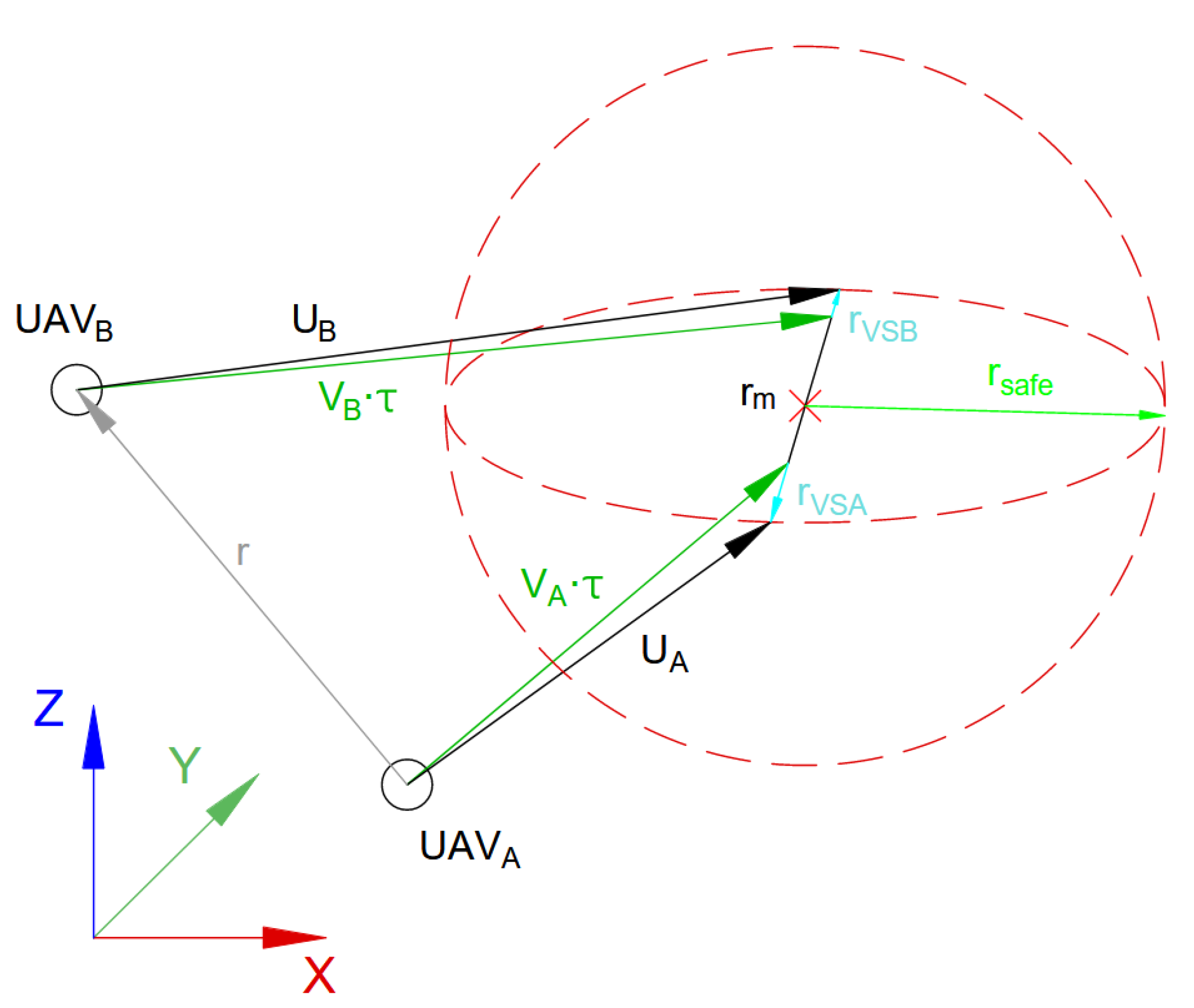
In this article, we focus on the particular situation in flight related to the need to maintain the separation between two platforms whose flight trajectories intersect (also taking into account time). In such a situation, a deterministic algorithm should be designed to ensure that the appropriate minimum distance between platforms is maintained. At the same time, aircraft must be equipped with systems that communicate data about their position to others. The presence of ADS-B modules on the platform is assumed, working both as emitters and receivers. These devices broadcast flight parameters (plane position, velocity, and heading) to nearby vehicles. Having minimal information on the position and velocities of nearby airplanes allows for effective and suboptimal dodge maneuver prediction.
There are three main approaches used in solving the task of separating platforms in the air, described in the literature on the subject. The first approach, the most natural and efficient, is based on determining the change in the direction of the UAV flight as well as the speed and height of the UAV based on the available data using geometric methods. These methods are characterised by a high speed of determining the solution. However, they require multiple repetitions in the case of minor modifications of the flight parameters of one of the air platforms. Geometric approaches rely on the analysis of the geometric attributes of the UAV to ensure that minimum distances between the air platforms are maintained. This requires calculating the time to potential collision using the distance between UAVs and their speed.
This article is mainly based on the geometric algorithm presented by Park, et al. [
9]. The method proposed by Park is tested to ensure flight safety in various situations. Different algorithm, described in [
19], allows the UAV to avoid obstacles of various types (including other UAVs) in 3D. Depending on the obstacle type identified and the information available about the obstacle, the algorithm determines the time when the UAV should start avoiding the obstacle. When the UAV reaches the point where obstacle avoidance begins, the algorithm starts the avoidance operation for a specified period of time. The length of the time window in which the UAV modifies the flight direction, is flexible and depends on the size and distance from the obstacle. After completing the obstacle avoidance maneuvers, the algorithm searches for new route points that will allow the UAV to return to the planned route as quickly as possible. The work [
20] also contains extensive literature review on collision avoidance algorithms. Peng et al. [
21] present a geometric model for UAVs where horizontal maneuvers are only performed by varying the speed of the UAV. The direction of flight remains constant. The model predicts the separation to be achieved by a horizontal collision avoidance maneuver. In addition, they calculate the effects of the speed change time and autopilot response on the horizontal miss distance and the reserved time to the nearest potential collision point.
The second group of methods is methods based on optimization, in particular, methods based on the principles of optimal control. Their description is out of the scope of this article due to their complexity. The reader interested in the theory of optimization is referred to the works of Pytlak [
22] and Betts [
23], who present direct and indirect methods in optimal control. In the case of optimal control, it is worth emphasizing that the task to be solved consists in determining the UAV flight trajectory between the starting and ending point, assuming the knowledge of the air platform flight dynamics model. The dynamics model is represented in the task in the form of state equations, which are subject to discretization during the determination of feasible solutions using one of the aforementioned methods. Ikeda et al. [
24] describe the collision avoidance problem as an optimal control task. The goal is to find a combination of safe maneuvers between the two UAVs that guarantees the longest minimum separation distance among possible escape maneuvers. The optimal control problem was formulated with quadratic performance criteria.
Many authors include among the set of algorithms that can be used in the process of determining the separation of platforms, UAV route planning algorithms based on the general VRP displacement planning task. For an example of the third group algorithm, see [
25]. It seems, however, that the use of integer methods for this purpose does not guarantee a short time of obtaining the result, because the general VRP problem belongs to the NP-hard problems class. The authors of the article also believe that the use of heuristic methods in the form of Genetic Algorithms or Particle Swarm Optimization (a good introduction can be found in the article [
26]) for this purpose, is also not a perspective path. For heuristic algorithms, it is not possible to determine convergence, which makes their use in control in the event of emergency situations very risky. In the case of system certification, it should rather be assumed that the certification authority may prevent the operation of the system with implemented algorithms of this class.
At this point, it is also worth noting that for several years there have been attempts to formalize the methods of testing models based on languages such as UML or SysML, as described, among others, in [
8]. However, testing according to these methods is a design task to which a separate team should be assigned. This topic is not covered in the article. The interested reader is referred to the papers described in the article [
8].
The final stage of the design work is the design of system testing procedures based on mission simulators and air tests. This includes the development of documentation rules for the most critical procedures affecting flight safety and the documentation of the tests performed. There are no clear guidelines for testing unmanned systems, but NATO and EU standards and norms are emerging [
8]. The most important standard in the design of unmanned aerial vehicles is certainly STANAG 4586 [
27], which presents general requirements for a UAV that would cooperate with various Ground Control Stations (GCS) and operate in a swarm with other platforms. Accompanying these standards are system design guidelines such as DO-1878C (System Building Guidelines [
10]), DO-331 [
14], DO-332 [
15] or DO-333 [
16]. In particular, the DO-331 standard-”Model-Based Development and Verification” is extremely important. The standard is an attachment to DO-178C and DO-278A. The equivalent of these guidelines is EMAR documents, which are also described in [
8].
3. Modeling of UAV Architecture
This section describes a practical example of modeling a selected unmanned aerial platform flight scenario, which considers the system’s response to selected emergency in flight situations. An example of a scenario will be the problem of maintaining the separation between two platforms, understood as a requirement not to exceed the minimum safe distance between platforms. The algorithm described in the article is implemented in the air platform Mission Computer and works automatically mainly when there is no communication with the GCS. When the radio link is active, the pilot has priority in making decisions on avoiding collisions with other platforms.
3.1. Selected Design Assumptions
The functional requirements and the requirements specified under the FHA are the bases for developing the system architecture and the detailed description of the aircraft flight scenarios. Each functional requirement is transformed, depending on the level of detail, into a scenario or a single function of the designed system. In the further part of the article, the operating models of the system in flight will be presented, taking into account the detection of a potential air collision of two air platforms equipped with ADSB systems.
Figure 1 shows a Use Case diagram covering the scenario presented in the article. We assume that the functional analysis of the system operation (FHA) has shown that a collision with another aircraft equipped with ADSB may occur during the flight of the platform. We also assume that the UAV may not be in contact with GCS at the time preceding the collision. The UAV itself is equipped with ADSB with the option of receiving the signal generated by other air platforms. Otherwise, the system should only prompt the pilot on possible action, but the final decision must always be with the pilot. Based on these assumptions, the model shown in the article was developed.
Use Cases map to State Machine diagrams that best represent the interactions occurring in concurrent systems. This modeling approach requires the determination of the following data:
- i.
How many states are to be that model for the described scenarios?
- ii.
What are the transitions between states?
- iii.
What are the emergency situations in flight, when can they occur, and what do they depend on?
- iv.
How to minimize the number of states describing emergency situations in flight so that the pilot can easily manage the system (particularly UAV computers)?
3.2. The Modeling of an Emergency Situation
In this section, a practical example of modeling an emergency situation in the flight of an unmanned platform will be presented, which concerns the response to a potential air collision of two platforms.
Figure 1 shows an exemplary Use Case model that describes the flight of the UAV in the WAYPOINT mode (flight along an a priori pre-set route consisting of many points). The basic Use Case must include handling an emergency situation in flight, which concerns the occurrence of a potential collision of air platforms that inform themselves about their positions using the ADSB system. The same applies to the avoidance of collisions with a terrain obstacle.
Figure 2 shows a general diagram of a State Machine for a Use Case that includes testing for the possibility of collision between air platforms during flight. The state machine model is shown, which describes the system’s operation during the flight in the WAYPOINT mode (automatic flight after the
a priori setpoints). All state changes occur within a single thread, which allows the use of a Mission Computer with lower performance (and thus smaller dimensions of the device). However, critical functions do not run in parallel, so the method of implementation described by the model is unacceptable for larger platforms.
Figure 3 shows the State Machine model, which describes the operation of the system in flight in the same mode. The handling of the flight to the following points is separate from checking for the occurrence of emergency situations. In this model, there are two parallel threads, each affecting how the other works. The critical functions for testing emergencies are performed serially in a separate thread. This implementation method is acceptable for larger platforms and does not consume a significant amount of computer resources (in this case, the Mission Computer).
Figure 3 shows a fragment of the State Machine model with selected actions in selected states. From a formal point of view, each state must have an action with the stereotype
do: that describes the processing that is performed in that state. This processing can be modeled as an activity or sequence diagram. In our case, the functions
do:testCollision() and
do:findWPT() are given numerical algorithms that are used to implement them. Collision testing is performed according to the Equations (
1) and (
2) (see
Section 4). It is worth noting that the determination of the collision situation takes a short time so that individual tests can be performed sequentially without risk. Determining a new flight direction is based on the Equations (
3) and (
4).
The basic scenario carried out by the UAV, which performs a flight in the route mode, consists in going through the following states in sequence:
(selection of the next waypoint, flight to a point, the configuration of the recognition sensor, checking for an emergency, and going to the selection of the next waypoint).
An alternative processing scenario will occur when a parallel process described in the [exceptional situation] state will execute the function, which will determine the UAV in a potential collision with the UAV. At this point, an alternative scenario is realized:
(following waypoint selection, flight to point, emergency test, emergency collision avoidance (do:findWPT() function, which determines the point to which the UAV must fly to avoid a collision), a continuation of the flight to a point, a test of the occurrence of an emergency, and selection of the next waypoint).
As part of handling emergency situations, potential collisions between aerial platforms and a collision with a terrain obstacle are tested. The reader may notice two entries from the state ExS2 to the state ExS1. It is not accidental. Depending on whether the possibility of a collision with a terrain obstacle was observed, the test of the potential collision of the aircraft may give different results. For example, in the event of a potential collision with a terrain obstacle, UAV algorithms must determine a route point above the obstacle, which ensures no collision with another UAV. By default, the platform can lower the flight altitude in certain situations, which is not possible in the event of a potential collision with a terrain obstacle. The processing itself is strictly dependent on the adopted rules and considerations that go beyond the article’s scope. They are issues bordering on aviation law.
473 The system’s physical architecture is designed after designing scenarios that take into account specific cases (emergency situations) in flight. A modern approach to the construction of unmanned platforms in line with the so-called Open architecture makes it possible to use commercial control systems even in military systems. Therefore, many modern UAVs use commercial Flight Control Computers (FCC), the functionality of which is extended by the use of a special Mission Computer (MC), which performs functions that cannot be performed with the use of FCC. A diagram of the architecture of the discussed unmanned system is shown in
Figure 4. Systems of this class have redundant FCC and MC computers.
Architecture refers to the physical components processing data in the system with indicating the types/roles of these elements (<<HWCI>> stereotype means Hardware Configuration Item). The figure shows selected subsystems embedded on platform computers. In particular, the subsystems responsible for the specific situation described in the article, related to the avoidance of air platform collisions, were indicated. In classic systems equipped with ADSB, the FCC detects the collision situation, but the collision avoidance algorithm itself can be performed as part of MC processes. It depends on the computational complexity of the algorithm used.
3.3. System Architecture with SIL Elements
This section shows the extensions of the physical architecture that concern the preparation of additional components simulating the operation of those systems that cannot be run during system tests in the laboratory. Due to the scope of the simulation performed and the used UAV physical components (GPS / INS and ADSB), it was decided to use the Software-in-the-Loop (SIL) simulation scheme. Software-in-the-Loop represents the integration of a production code into a mathematical model simulation, providing engineers with a virtual simulation environment for the development and testing of complex systems. SIL makes it possible to test the software before the hardware prototyping phase and accelerates the development cycle. SIL enables the earliest detections of system-level defects or bugs.
Testing of complex systems, in particular those that can cause harm to humans, must be performed in conditions similar to reality. In this sense, simulators of real systems are built. If most or part of the critical UAV systems is simulated by software, it is referred to as SIL (Software-in-the-Loop) simulator testing. This approach has many disadvantages, the main of which is the need to prove that the software simulator corresponds precisely to the software embedded on the actual platform. In this respect, the most difficult thing is to simulate the computing power, including the processors’ load. In addition, systems often use a different architecture associated with differences in the interpretation of variables and how some operations are performed. However, it is not easy to test a system other than based on SIL in some situations. Examples include simulating collisions of unmanned aerial vehicles, simulating a collision with a terrain obstacle, or simulating GPS/INS signal interference. In the case of GPS/INS systems, modern systems are so intelligent that it is impossible to substitute GPS position data to the device to simulate a flight. Therefore, in most cases, GPS/INS signal interference is tested based on SIL. The presented approach simulates the operation of GPS/INS spatial orientation systems and the ADSB system’s operation, which generate information about UAVs whose flight trajectories may cause an air collision with our UAV. The SIL scheme is sufficient in this case to test the correctness of the designed algorithm. The SIL architecture integrated with GCS and UAV elements is shown in
Figure 5.
When testing the collision avoidance procedures, one can use the software embedded on the real Mission Computer (MC). The change in the platform’s position is still simulated by software, but algorithms are used to determine new flight courses embedded in the MC. At this point, we can talk about the Hardware-in-the-Loop (HIL) class simulation, in which original elements of the air platform are used. However, in order to consider the simulation environment to meet the requirements of the HIL test environment fully, an FCC would have to be added to this environment, which would be fed with the necessary data about the platform position and the status of onboard equipment. However, it is not necessary to properly test the collision avoidance algorithm.
6. Conclusions
The article discusses the methods of designing a reliable hardware and software architecture of unmanned aerial vehicles, that consider the modeling of emergency situations in the flight. The models and results are for a medium-range UAV system subject to certification regulations under current EU legislation. Therefore, it should be assumed that these platforms will be subject to a certification process similar to that to which airplanes are subject.
The article focuses primarily on the methods of modeling scenarios implemented by the platform in flight, using the technique of functional threat analysis and failure trees of elements included in the hardware and software architecture of the system. It will not be an overstatement to say that this approach will soon dominate companies producing flying systems.
Particular attention was paid to describing methods of modeling the collision avoidance behavior in a flight of two platforms equipped with ADSB devices. One of the better algorithms has been referred to, which gives a deterministic solution to the above problem. Ways to test this algorithm are provided. It was shown that the descriptions of the algorithm in the source article contained inaccuracies that could cause errors in the platform or its unexpected reactions in real-world conditions. The simulation tests proved it, and an analytical solution was given, an extension of the base algorithm. The article focuses on the principles of designing system test plans and designing individual test cases to verify the system’s operation in the event of emergency situations in flight. We also present the air platform flight simulator that we use in practice in the form of a SIL model based on selected algorithms for avoiding dangerous situations.
Further work will go in two directions. First of all, the model should be extended with additional algorithms for reacting to emergencies, such as, for example, ensuring separation from a terrain obstacle or maintaining the UAV flight in the permitted area. Secondly, the described simulator should be expanded to a full HIL model using additional equipment. However, this requires the construction of simulators of mechanical components such as the engine, which is a separate project due to the complexity of the task.


