1. Introduction
Chemical fertilizer as an important means of agricultural production, is made by chemical or physical methods to contain one or several nutrient elements required for the growth of crops. In order to ensure the yield and quality of crops, it plays an important role in ensuring the safety of food production and the high efficiency and high yield of agriculture [
1]. However, in recent years, the excessive application of chemical fertilizers, the low utilization rate, and the unreasonable proportion of trace elements have caused more serious social problems such as environmental pollution, resource pressure, and ecological destruction. As a result, the organic matter content of cultivated land has been greatly reduced, the soil has become increasingly acidified and compacted, and the quality of agricultural products has declined, which is not conducive to the sustainable development of agriculture [
2,
3,
4,
5]. Precision fertilization is based on the soil nutrient content and variable fertilization on demand. Proved by practice, it is an effective way to solve the unreasonable fertilizer input and ratio, low fertilizer utilization rate, and agricultural ecological environmental pollution. In addition, it can significantly improve economic, social, and ecological benefits, which is the development direction of fertilization technology in the future [
6,
7,
8].
The main structural forms of the existing variable fertilizer discharging device include outer groove wheel type, centrifugal type, spiral type, vibrating type, star wheel type, etc. [
9]. However, since most of the chemical fertilizers used in base fertilizer at home and abroad are granular, the outer groove wheel type fertilizer discharging device is mostly used. Mostly, the rotation speed of the outer groove wheel type fertilizer discharging shaft is changed to realize the adjustment of the fertilizer amount, that is, the single variable fertilizer discharging. Experts and scholars [
10,
11] at home and abroad had done a lot of research on variable fertilization with grooved wheels, Japanese scholars had developed a variable fertilizer applicator suitable for paddy field operations. It used a Direct Current power (DC) stepper motor to drive the fertilizer discharging device. It implemented variable fertilization operations based on the onboard computer and the operation prescription map; the SOILEC-TION fertilizer applicator produced by Ag-chen in the United States could apply solid or liquid fertilizer as needed according to the fertilization prescription map [
12]; Kyoto University [
13] developed a variable rate fertilizer applicator. By controlling the rotation speed of the driving motor connected with the fertilizer discharging mechanism, the purpose of regulating the discharge amount of fertilizer was achieved. Zhang Shuhui et al. [
14] used a single-chip microcomputer to control the speed of the fertilizer discharging shaft of the fertilizer applicator and developed a continuously adjustable variable fertilization control system; Han Guangyi et al. [
15] designed a precision fertilization device and adopted an external trough type fertilizer device. There was an insert plate on the fertilizer pipe, which could adjust the amount of fertilizer according to the movement of the insert plate. At the same time, it could prevent the fertilizer pipe from clogging. The univariate fertilization method is simple in structure and easy to control. It has been widely used, but the accuracy and range of fertilization adjustment are small. Especially when the amount of fertilization is small or the rotation speed of the fertilizer shaft is too low, it is easy to cause the pulsation of the fertilizer discharge of the outer groove wheel to be significant. It seriously affects the uniformity of fertilization. Additionally, too high rotation speed can easily reduce the accuracy of fertilization and increase the rate of seed damage [
16].
In order to solve the above problems, scholars have proposed a two-variable fertilization method. That is to control the amount of fertilizer by adjusting the opening of the fertilizer outlet and the speed of the fertilizer shaft. ALAMEEN et al. [
17] realized automatic adjustment of the opening of the fertilizer outlet through the air cylinder. Based on this, a two-variable fertilization control system was developed. Liu Chengliang et al. [
18] designed a dual-variable (fertilizer outlet opening, fertilizer shaft speed) adjustable fertilization control system. Zhang Lixin et al. [
19,
20] developed a variable fertilizer applicator and used tractor as power source. It could realize the dual-variable adjustment of the speed of the fertilizer shaft and the opening of the grooved wheel. The two-variable fertilization method greatly improves the range and accuracy of fertilization. It effectively improves the accuracy and flexibility of variable fertilization control. However, it faces the same problem as the univariate fertilizer method, that is, only single fertilizer and compound fertilizer can be applied. European and American technology companies, RDS, CASE, Ag Leader, etc., developed and have been put on the market. After continuous practice, it was proved that precise fertilization can reduce the application of fertilizer and improve the quality of crops. Among them, N, P, K split application was more conducive to controlling the amount of fertilizer on demand and reducing fertilizer waste, and had strong practicability and promotion value [
10,
13]. The above results play an important role in further research on the mixing of various fertilizers in different proportions. It can effectively realize accurate variable fertilization.
In order to change the traditional unreasonable uniform fertilization or single fertilization method and realize the mixing of various fertilizers in different proportions, this study takes the Zhongji Miele 1304 cultivating fertilizer applicator as the research object. A variable formula fertilization control system composed of pressure sensors, speed sensors, servo motors, on-board control terminals, and fertilization actuators based on the Programmable Logic Controller (PLC controller) was designed. Additionally, based on the soil fertilization prescription diagram, the three kinds of nitrogen, phosphorus, and potassium fertilizers are quickly and automatically formulated as needed, in order to achieve accurate variable fertilization. It can effectively improve fertilizer utilization and reduce production costs.
2. Materials and Methods
The variable formula fertilizer applicator system of the Zhongji Miele 1304 field fertilizer applicator consists of three major parts: the variable formula fertilizer mechanical structure, the control system, and the software system.
2.1. Design of Variable Formula Fertilizer Machinery Structure
The variable formula fertilization mechanical structure of the Zhongji Miele 1304 cultivating fertilizer applicator consists of a suspension mechanism, a frame, a soil plow, a plastic device, a fertilizer tank, a trough wheel type fertilizer device, a ground wheel, a pressure sensor, a speed sensor, a servo motor, PLC controller, vehicle control terminal, and other components, as shown in
Figure 1.
The test prototype adopts a symmetrical structure design. The number of working rows is 4, and the working width is 3.6 m. In order to realize the fast and automatic formula of nitrogen, phosphorus, and potassium fertilizers and the function of precise variable fertilization, the fertilizer tank adopts a double-layer structure. The top layer is divided into 3 groups, with 2 fertilizer tanks in each group (1 on the left and right sides). It carries 3 kinds of fertilizers: nitrogen, phosphorus, and potassium, and there are 3 fertilizer outlets under each fertilizer tank. There are a total of 6 grooved wheel fertilizer discharging devices in each group, driven by a hexagonal fertilization drive shaft. It has a total of 3 fertilization drive shafts, which are connected to the servo motor. Its speed is controlled by 3 servo motors, respectively, to realize the proportional mixing of various fertilizers. There are 2 fertilizer tanks in the bottom layer (1 on the left and right sides). It is used to load and mix the 3 fertilizers of nitrogen, phosphorus, and potassium that have been completed in accordance with the soil prescription diagram in the top fertilizer tank. There are 2 fertilizer outlets under each fertilizer tank, and the lower hopper corresponds to the fertilizer outlet one by one. It has a total of 4 slot-wheel fertilizer discharging devices, driven by a hexagonal fertilization drive shaft. The fertilization drive shaft is connected with a servo motor, and its speed is controlled by the servo motor to achieve precise fertilization of various fertilizers.
Servo motor purchase Beijing Times Superior 60A4A04030-SCA model. The rated output power is 400 W, the rated speed is 3000 r/min, and the rated torque is 1.27 N·m. Refer to the research results of Weiliguo et al. [
6]. The normal discharging torque of the drive shaft of the fertilizing and discharging machine should be greater than 36 N·m. Therefore, in order to increase the working torque of the motor, a geared motor with a reduction ratio of 1:30 is connected to the output shaft end of the servo motor. It adopts the Beijing Times Superior PXW80 right-angle planetary reducer to meet the transmission requirements. In addition, the tractor voltage is converted into the working voltage of the servo motor, pressure sensor, speed sensor PLC controller, and on-board control terminal by using the transformer module. It purchases the DC power converter produced by Guangzhou Dexuan Electronics to provide continuous and stable power for the components of variable formula fertilization.
2.2. Design of Variable Formula Fertilizer Control System
2.2.1. System Overall Scheme Design
The variable formula fertilization control system based on the prescription map is mainly composed of pressure sensors, speed sensors, servo motors, fertilization actuators, PLC controllers, and vehicle control terminals. The overall design structure is shown in
Figure 2. The modules of the system work according to the pre-established communication protocol. The pressure sensor combines the fertilizer weight detection signal and the speed sensor to the ground wheel speed detection signal, which are quickly collected by the PLC controller, filtered, scaled, and non-linearly corrected. It is transmitted to the vehicle control terminal for display, combined with the feedback data information of the soil prescription diagram, and the formula fertilization control strategy and instructions are obtained through calculation. It sends to the PLC controller to execute commands to control the speed of the servo motor and realize the function of variable formula fertilization.
2.2.2. Speed Sensor
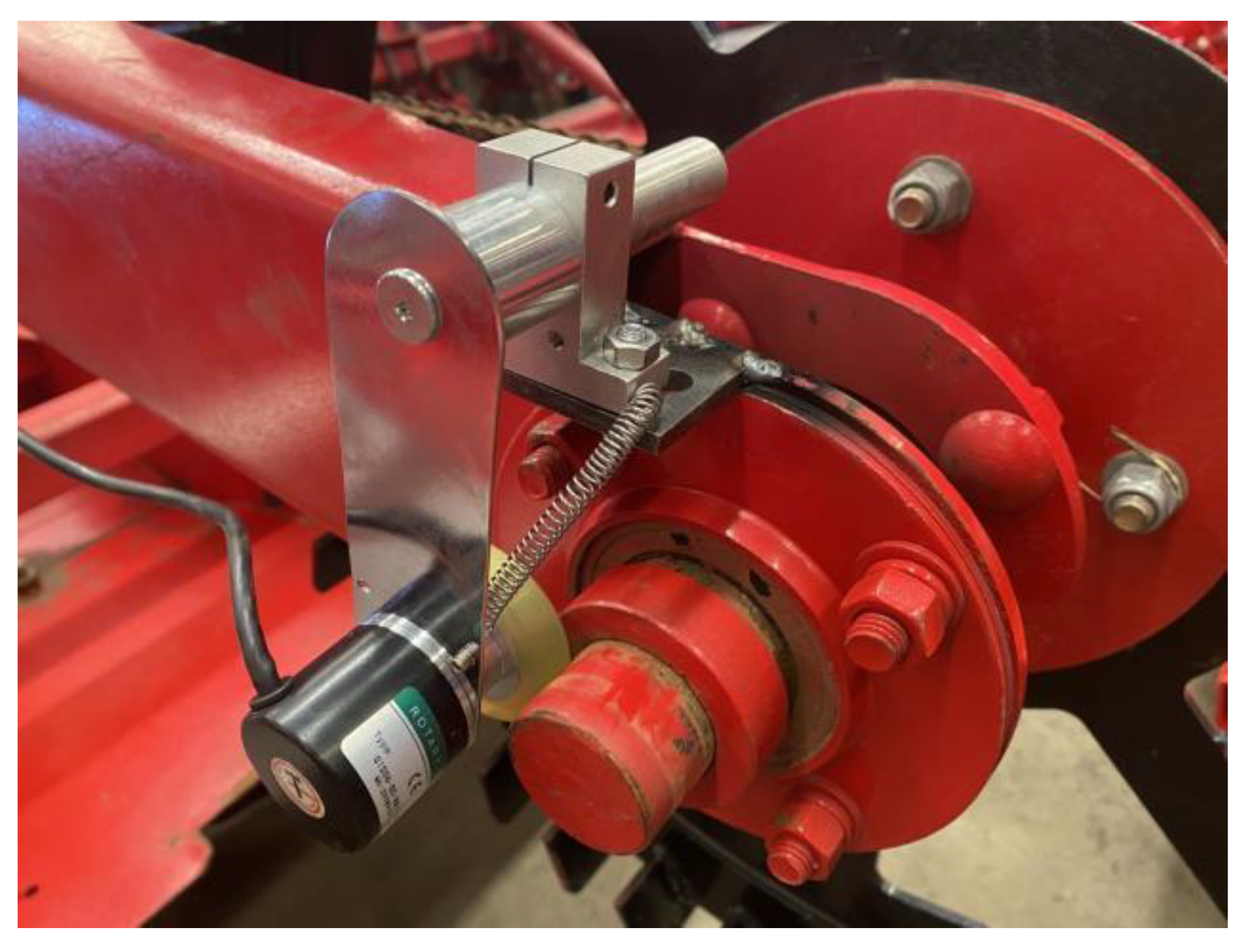
The forward speed of the cultivating fertilizer applicator is an important detection parameter of variable formula fertilization [
21]. In this study, the incremental rotary encoder (AB two-phase, 100 pulses) produced by JTS encoder is selected. It has strong anti-interference and high cost performance, and it is installed on the ground wheel of the test prototype (as shown in
Figure 3).
Through the rotating grating disc and optocoupler, the direction-recognizable counting pulse signal is generated. It is transmitted to the PLC controller to calculate the rotation speed of the ground wheel (that is, the machine’s forward speed), and obtain the movement data information of the machine’s forward speed in real time. However, due to the slipping phenomenon of the ground wheel, the coefficient of ground wheel slip must be considered, and the actual ground wheel speed calculation equation is:
Substituting
d = 0.76 m and
n = 100 into the above equation, simplifying to get:
where
v is the forward speed of the machine tool, m/s;
n is the number of speed measurement pulse signals per revolution of the encoder, taking 100;
T is the speed measurement period, s;
T is the speed measurement period, s;
N is the number of pulses in
T time;
d is the diameter of the speed measuring wheel, which is 0.76 m;
ε is the slip rate, generally 0.05~0.12 [
8].
2.2.3. Pressure Sensor
In order to achieve the purpose of variable formula fertilization, the DYDW-011 cantilever beam sensor (range 1000 kg) produced by Dayang Sensor Company was selected in this study. It has the characteristics of stable and reliable performance and high precision. The bottom surface of each fertilizer tank is supported by 4 cantilever beam sensors. One end is fixed on the frame, and the other end bears the fertilizer gravity of the fertilizer tank. During the installation process, it is necessary to ensure that the force of the four connection points of each fertilizer tank is basically the same (as shown in
Figure 4). The change in the amount of fertilizer in the fertilizer tank will cause the pressure sensor signal to change. When the PLC controller performs signal acquisition, it adopts the proportional measurement method. In order to eliminate the influence of uneven fertilizer in the fertilizer tank or the tilt of the fertilizer tank on the measurement results of the pressure sensor, the signal value of the pressure sensor is filtered, scaled, and non-linearly corrected. Then the equation for calculating the weight of each fertilizer tank is:
where
mn is the weight of top fertilizer tank fertilizer n (0 ≤
n ≤ 3,
n is an integer), kg;
k is the sensor output voltage-weight ratio coefficient, kg/mV;
Vn0 is the output signal of top fertilizer tank fertilizer ground pressure sensor 0, mV;
Vn1 is the output signal of top fertilizer tank fertilizer
n ground pressure sensor 1, mV;
Vn2 is the output signal of top fertilizer tank fertilizer
n ground pressure sensor 2, mV;
Vn3 is the output signal of top fertilizer tank fertilizer
n ground pressure sensor 3, mV;
Vn4 is the output signal of top fertilizer tank fertilizer
n ground pressure sensor 4, mV;
md is the weight of bottom tank, kg;
Vd1 is the output signal of bottom fertilizer tank fertilizer ground pressure sensor 1, mV;
Vd2 is the output signal of bottom fertilizer tank fertilizer ground pressure sensor 2, mV;
Vd3 is the output signal of bottom fertilizer tank fertilizer ground pressure sensor 3, mV;
Vd4 is the output signal of bottom fertilizer tank fertilizer ground pressure sensor 4, mV.
2.2.4. Fertilizer Drive System
The fertilizer discharge drive system is composed of a servo motor drive system, a fertilizer discharge actuator, a PLC controller, etc. Among them, the servo motor drive system includes servo motor, servo motor driver and reducer; the discharging actuator includes a trough wheel type fertilizer discharging device and a discharging shaft, as shown in
Figure 5. In the process of fertilization, the PLC controller performs calculations based on the soil prescription map, the forward speed information of the equipment detected by the speed sensor, and the actual fertilizer output data detected by the pressure sensor. It calculates the formula fertilization data information that the servo motor should reach and sends instructions to the drive. It adjusts the speed of the servo motor, and then controls the proportion of the formula and the amount of fertilizer.
In order to achieve precise control of variable formula fertilization, it is necessary to accurately calculate the fertilizer output of the grooved wheel fertilizer [
22]. According to the working principle of the grooved wheel fertilizer discharging device and the analysis based on the basic knowledge of agricultural machinery design: the amount of fertilizer discharged per revolution of the grooved wheel is composed of the weight of the fertilizer carried between the outer side of the grooved wheel and the shell and the weight of the fertilizer forcedly discharged by the grooved wheel. Then, its calculation formula [
23,
24] is:
That is, the amount of fertilizer discharged per revolution of the grooved wheel is:
where
Q is the weight of fertilizer discharged per revolution of the grooved wheel, g/r;
Q1 is the weight of fertilizer brought out between the outer side of the sheave and the shell, g/r;
Q2 is the weight of fertilizer forced to be discharged by the groove wheel, g/r;
τ is the fullness factor of the fertilizer in the groove of the grooved wheel;
z is the number of grooves in the sheave;
ρ is the density of fertilizer particles, g/cm
3;
s is the cross-sectional area of a single groove, mm
2;
l is the effective working length of the grooved wheel, mm;
r is the radius of the groove wheel, mm;
λ is the fullness coefficient of the driving layer fertilizer.
2.3. Design of Variable Rate Fertilization Software System
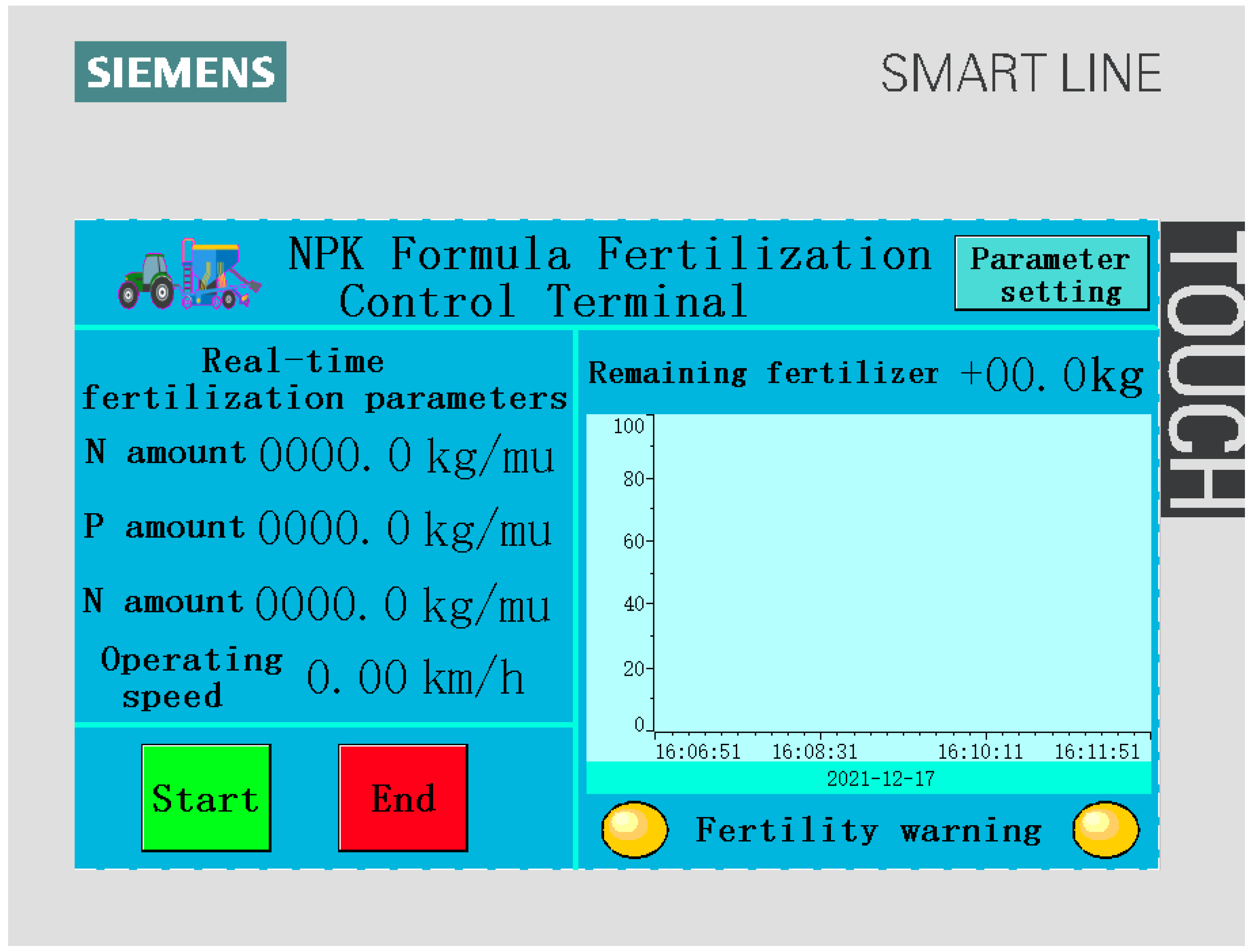
The variable formula fertilization software system includes module functions such as sensor data collection and display, prescription map data loading, variable formula fertilization decision-making, data storage, and playback. The sensor data collection module can collect information such as fertilizer flow rate, machine forward speed, and mixing ratio of nitrogen, phosphorus, and potassium. According to the current machine forward speed information and the actual fertilizer discharge data, the variable fertilization decision based on the soil prescription map is generated. It sends the formula fertilization control instructions to the PLC controller in real time to realize the on-demand fast formula and variable precision fertilization function. The parameter data in the process of variable formula fertilization is displayed in real time by the SMART LINE V3 touch screen. The operating interface software program is programmed by WinCC flexible SMART V3 language. The vehicle control terminal software program is written in the Utility Mansger language, and the software operation interface is shown in
Figure 6.
After the system starts, it performs initial configuration. The PLC controller communicates with the human–computer interaction module (touch screen). It also loads the soil prescription map and reads the initial control instructions. It also obtains the value of each control parameter through the corresponding protocol analysis. The speed sensor transmits the detected ground wheel rotation pulse signal to the PLC controller. The forward speed of the implement is obtained by calculation (Equation (2)). The pressure sensor transmits the detected fertilizer tank fertilizer pressure signal to the PLC controller. Through calculation, the weight of each fertilizer tank is obtained (Equation (3)). Based on the data information of the soil prescription map and combined with the machine forward speed feedback data, the system transmits it to the PLC controller. According to the theoretical fertilizer capacity of the grooved wheel (Equation (5)), the speed of each servo motor is calculated. At the same time, the PLC controller adjusts the PWM duty cycle signal and incremental PID algorithm according to the instruction to regulate the speed of the servo motor. It can realize fast variable formula and precise fertilization operation. The software program flow is shown in
Figure 7. The incremental PID control algorithm formula is:
where
un is the output value of the controller at the
n sampling time;
un − 1 is the output value of the controller at the
n − 1 sampling time;
is the controller increment;
en is the control deviation of the controller at the
n sampling time;
en − 1 is the control deviation of the controller at the
n − 1 sampling time;
en − 2 is the control deviation of the controller at the
n − 2 sampling time.
3. Results and Discussion
3.1. Pressure Sensor Calibration Test
In order to accurately determine the weight change of fertilizer in the fertilizer tank, it was necessary to calibrate the pressure sensor of the fertilizer tank. First, the China Machinery Miele 1304 field cultivating fertilizer applicator was placed on the flat ground, and the pressure sensor measurement value was recorded when the fertilizer tank was empty; next, 5 standard weights (50 kg) were put into the fertilizer tank in turn, and the pressure sensor measurement value was recorded after each load; finally, the 5 standard weights were taken out from the fertilizer tank in turn, and the pressure sensor measurement value was recorded after each unloading. The repeatability of the above measurement test was carried out 3 times, and the measurement results are shown in
Table 1. The calibration coefficient
K of the pressure sensor was calculated based on this:
where
mf is the weight value of the standard weight (50 kg), kg;
is the absolute value of the difference between the measured value of the pressure sensor when loading or unloading a standard weight (2 ≤ n ≤ 5, n is an integer), kg.
From this, the real-time weight value of the fertilizer in the fertilizer tank could be obtained:
where
mc is the real-time measured value of the pressure sensor, kg;
mk1 is the weight value of no-load top fertilizer tank, kg;
mk2 is the weight value of no-load bottom fertilizer tank, kg;
ms1 is the real-time weight value of top fertilizer, kg;
ms2 is the real-time weight value of bottom fertilizer, kg.
After the calibration of the pressure sensor was completed, the measurement accuracy of the pressure sensor needed to be checked here. According to the above test method, the standard weight (50 kg) was loaded and unloaded into the fertilizer tank in turn. The measured value of the pressure sensor was recorded and the above measurement test was repeated 3 times. The measurement results are shown in
Table 1. After calculation, it could be known that the error range of the measured value of the pressure sensor was 0.005~0.03%, which met the requirements of weighing measurement accuracy.
3.2. Test on the Displacement Measurement of Fertilizer Discharger
In order to achieve the purpose of precise fertilization, it was necessary to determine the discharge capacity of different fertilizer dispensers [
25,
26]. The test materials were commonly used granular fertilizers: urea (N), diammonium phosphate (P), and potassium sulfate (K). Before the test, the fertilizer was put into the fertilizer tank, and the servo motor was controlled through the PLC controller. It drove the trough wheel type fertilizer discharging device to rotate at a certain speed and put the material receiving container at the fertilization outlet. The fertilizer amount could be obtained by weighing the weight of the fertilizer in the receiving vessel. Then, a stopwatch was used to time the fertilizer discharge. The test was repeated 3 times for each fertilizer device at each speed. The test results are shown in
Table 2 and fertilizer discharge measurement test is shown in
Figure 8.
According to the test results in
Table 2, in the controller, three gears of low, medium, and high were set up for the motor speed, corresponding to the motor speed of 10, 30, and 50 r/min, respectively. Then, the corresponding calibration data nitrogen (N) average fertilizer outputs were 52.4, 46.9, and 41.8 g/r, and the standard deviations were 1.3, 2.8, and 1.2, respectively; phosphorus (P) average fertilizer outputs were 64.3, 60.3, and 55.8 g/r, and the standard deviations were 2.9, 3.1, and 0.8, respectively; potassium (K) average fertilizer outputs were 86.0, 82.7, and 79.4 g/r, and the standard deviations were 1.0, 4.3, and 1.1, respectively.
It could be seen that potassium fertilizer discharged the largest amount of fertilizer per turn, followed by phosphate fertilizer, and nitrogen fertilizer was the smallest, because the bulk density of the three fertilizers of nitrogen, phosphorus, and potassium was different. The amount of fertilizer per revolution of the grooved wheel type fertilizer discharging device is larger at low speed and smaller at high speed, which is mainly related to the weight of the fertilizer carried between the outer side of the groove wheel and the outer shell. The standard deviation of the fertilizer output per revolution was different for the three kinds of fertilizers of nitrogen, phosphorus, and potassium at different speeds. Nitrogen fertilizer was the largest, followed by phosphate fertilizer, and potassium fertilizer was the smallest, because the fluidity of the three fertilizers of nitrogen, phosphorus, and potassium is different.
3.3. Speed Sensor Calibration Test
Accurate measurement of the forward speed of the cultivating fertilizer applicator was related to the calculation and control accuracy of the fertilizer output of the variable formula fertilization system, and the speed test work was required. The Zhongji Miele 1304 cultivating fertilizer applicator kept driving at a constant speed within the range of 3~6 km/h and recorded the driving time of its passing through the calibration interval (100 × 5 m). After the conversion of Equation (2), the calculation formula of slip rate was:
In this study, 6% of the forward speed of the field fertilizer applicator was selected as the forward slip rate of the implement. In order to check the accuracy of the speed measurement, the test was repeated 3 times and the average value was taken. It used the ratio of the advance distance to the advance time as the actual speed. The detection speed was calculated by Equation (2), and the test results are shown in
Table 3. In the experiment, the accuracy of speed measurement was above 98%, which met the requirements of variable formula fertilization speed measurement experiment.
3.4. Test Verification of Variable Rate Formula Fertilization Control System
In order to verify the accuracy of the variable formula fertilization control system, the experiment was carried out in Zhongji Minuo Technology Co., Ltd., Gu’an County, Hebei Province. The repeatability was the average value of 3 times. The test verification is shown in
Figure 9, and the actual control system is shown in
Figure 10. The feed weight, actual fertilization weight, target fertilization amount, fertilization area, target fertilization weight, and other data were recorded, and the statistical results are shown in
Table 4.
The actual fertilization weight was obtained by the method of receiving and weighing in a container, and the fertilization prescription map was generated according to the fertilization guide amount. The vehicle-mounted control terminal performed calculations based on the soil prescription map, the forward speed information of the machine detected by the speed sensor, and the actual fertilizer output data detected by the pressure sensor. It calculated the formula fertilization data that the servo motor should reach and sent instructions to the drive to adjust the speed of the servo motor, and then controlled the formula ratio and fertilization amount.
It could be seen from
Table 4 that using N, P, K in a non-quantitative manner, the formula control error was less than 5%; The fertilizer control error was 1.08%, 2.79%, 1.84%, respectively. The control accuracy of the variable formula fertilization system had reached more than 98%, which met the requirements of variable formula and precise fertilization.
In order to further verify the performance of the variable formula fertilization control system, according to the N, P, K target fertilization weight data in
Table 4, it was tested and compared with the traditional uniform fertilization operation. The comparison results of the actual fertilization amount data are shown in
Table 5.
It could be seen from
Table 5 that compared with the traditional uniform fertilization operation, this variable formula fertilization control system saved an average of 1.14 kg of chemical fertilizer per mu (that was to save 17 kg per hectare). It could effectively save chemical fertilizers and reduce operating costs and had good economic benefits.
4. Conclusions
(1) Taking the Zhongji Miele 1304 cultivating fertilizer applicator as the research object, designing a variable formula fertilization control system composed of pressure sensors, speed sensors, servo motors, vehicle-mounted control terminals, and fertilization actuators with PLC controller as the core. Based on pre-loaded soil prescription diagram and combining fertilizer pressure and ground wheel speed detection information, the system obtained a formula fertilization control strategy through calculation to realize the rapid and automatic formula of nitrogen, phosphorus, and potassium fertilizers and the precise variable fertilization.
(2) The experiment researched the performance of the variable formula fertilization control system, carried out pressure sensor calibration, fertilizer discharge measurement, and speed sensor test. The results showed that the error range of the pressure sensor measurement value was 0.005~0.03%, which satisfied weighing measurement accuracy requirements; in the controller, three gears of low, medium, and high were set up for the motor speed, corresponding to the motor speed of 10, 30, and 50 r/min, respectively. Then, the corresponding calibration data nitrogen (N) average fertilizer outputs were 52.4, 46.9, and 41.8 g/r, and the standard deviations were 1.3, 2.8, and 1.2 respectively; phosphorus (P) average fertilizer outputs were 64.3, 60.3, and 55.8 g/r, and the standard deviations were 2.9, 3.1, and 0.8, respectively; potassium (K) average fertilizer outputs were 86.0, 82.7, and 79.4 g/r, and the standard deviations were 1.0, 4.3, and 1.1, respectively; the measurement accuracy of the speed sensor was above 98%, which met the requirements of the variable formula fertilization test speed test.
(3) In the process of experimental verification, the formula control error was less than 5%, and the fertilizer control error was 1.08%, 2.79%, 1.84%, respectively. The control accuracy of the variable formula fertilization system had reached more than 95%, which met the requirements of variable formula and precise fertilization. In addition, compared with the traditional uniform fertilization operation, this variable formula fertilization control system saved an average of 1.14 kg of chemical fertilizer per mu (that was to save 17 kg per hectare). It could effectively save chemical fertilizers and reduce operating costs and had good economic benefits.
Most of the variable formula fertilization control system currently studied can only complete the application of single fertilizer and compound fertilizer. However, the study in this paper compares with other variable formula fertilization control systems, it can realize the mixing of various fertilizers in different proportions and change the traditional unreasonable uniform fertilization or single fertilization method. It has strong practicability and promotion value.
The scientific and effectiveness of the soil fertilization prescription map is very important to the variable formula fertilizer applicator. The control accuracy of the variable formula fertilization controller had a great relationship with the fertilization flow rate and the accuracy of the vehicle speed detection. In the follow-up, further experiments are needed to verify and optimize the variable fertilizer applicator system to improve its economy and practicability.
Author Contributions
Conceptualization, L.Z. and L.L.; methodology, K.N. and D.Y.; software, S.B.; validation, S.B. and W.Z.; formal analysis, K.N. and S.B.; investigation, S.X.; resources, L.Z.; data curation, S.B.; writing—original draft preparation, S.B.; writing—review and editing, K.N. and Y.Y.; visualization, K.N.; supervision, Y.Y.; project administration, B.Z.; funding acquisition, L.Z. and B.Z. All authors have read and agreed to the published version of the manuscript.
Funding
This work was mainly supported by the National Key Research and Development Program of China (Grant No. 2019YFB1312302).
Data Availability Statement
Data are contained within the article. The data presented in this study can be requested from the authors.
Conflicts of Interest
The authors declare no conflict of interest.
References
- Tang, H.; Wang, J.W.; Xu, C.X.; Zhou, W.Q.; Wang, J.F.; Wang, X. Research Progress Analysis on Key Technology of Chemical Fertilizer Reduction and Efficiency Increase. Trans. Chin. Soc. Agric. Mach. 2019, 4, 1–19, (In Chinese with English Abstract). [Google Scholar]
- Meng, Z.J.; Zhao, C.J.; Liu, H.; Huang, W.Q.; Fu, W.Q.; Wang, X. Development and performance assessment of map-based variable rate granule application system. J. Jiangsu Univ. (Nat. Sci. Ed.) 2009, 4, 338–342, (In Chinese with English Abstract). [Google Scholar]
- Yang, L.; Yan, B.X.; Zhang, D.X.; Zhang, T.L.; Wang, Y.X.; Cui, T. Research progress on precision planting technology of maize. Trans. Chin. Soc. Agric. Mach. 2016, 11, 38–48, (In Chinese with English Abstract). [Google Scholar]
- Zhao, C.J. Strategy thinking on precision agriculture of China. Agric. Netw. Inf. 2010, 4, 5–8, (In Chinese with English Abstract). [Google Scholar]
- An, X.F.; Fu, W.Q.; Wang, P.; Wei, X.L.; Li, L.W.; Meng, Z.J. Development of Variable Rate Fertilization Control System Based on Matching Fertilizer Line and Seed Line of Wheat. Trans. Chin. Soc. Agric. Mach. 2019, S1, 96–101, (In Chinese with English Abstract). [Google Scholar]
- Wei, L.G.; Zhang, X.C.; Yuan, Y.W.; Liu, Y.C.; Li, Z.L. Design and experiment of 2F-6-BP1 variable rate assorted fertilizer applicator. Trans. Chin. Soc. Agric. Eng. 2012, 7, 14–18, (In Chinese with English Abstract). [Google Scholar]
- Yuan, Y.W.; Li, S.J.; Fang, X.F.; Wei, L.G.; Liu, Y.C. Decision Support System of N, P and K Ratio Fertilization. Trans. Chin. Soc. Agric. Mach. 2013, 44, 240–244, 233, (In Chinese with English Abstract). [Google Scholar]
- Zhang, J.C.; Yan, S.C.; Ji, W.Y.; Zhu, B.G.; Zheng, P. Precision Fertilization Control System Research for Solid Fertilizers Based on Incremental PID Control Algorithm. Trans. Chin. Soc. Agric. Mach. 2021, 3, 99–106, (In Chinese with English Abstract). [Google Scholar]
- Shi, Y.Y.; Chen, M.; Wang, X.C.; Odhiambo, M.O.; Zhang, Y.N.; Ding, W.M. Analysis and Experiment of Fertilizing Performance for Precision Fertilizer Applicator in Rice and Wheat Fields. Trans. Chin. Soc. Agric. Mach. 2017, 7, 97–103, (In Chinese with English Abstract). [Google Scholar]
- Iida, M.; Umeda, M.; Radite, P.A.S. Variable Rate Fertilizer Applicator for Paddy Field. In Proceedings of the 2001 ASAE Annual International Meeting, Sacramento, CA, USA, 29 July–1 August 2001. [Google Scholar]
- Mikio, U.; Toshikazu, K.; Michihisa, I.; Choung, K.L. Effect of Variable Rate Fertilizing for Paddy Field. In Proceedings of the 2001 ASAE Annual International Meeting, Sacramento, CA, USA, 29 July–1 August 2001. [Google Scholar]
- Macalalad, E.P.; Thai, L.C.; Wu, J. Performance evaluation of different ionospheric models in single-frequency code-based differential GPS positioning. GPS Solut. 2016, 2, 173–185. [Google Scholar] [CrossRef]
- Yang, C.; Everitt, J.H.; Bradford, J.M. Comparisons of uniform and variable rate nitrogen and phosphorus fertilizer applications for grain sorghum. Trans. Am. Soc. Agric. Eng. 2001, 44, 201–209. [Google Scholar] [CrossRef]
- Zhang, S.H.; Ma, C.L.; Wu, C.C.; Du, Q.L.; Han, Y.X.; Zhao, X.M. Development and application of a variable rate fertilizer applicator for precision agriculture. Trans. Chin. Soc. Agric. Eng. 2003, 1, 129–131, (In Chinese with English Abstract). [Google Scholar]
- Han, G.Y.; Liu, S.C. Hole Fertilization Precision Seeder. Patent No. CN2423704, 21 March 2001. (In Chinese with English Abstract). [Google Scholar]
- Gu, Y.X.; Yu, J.; Liu, C.L. FIS-based method to generate bivariate control parameters regulation sequence for fertilization. Trans. Chin. Soc. Agric. Eng. 2011, 11, 134–139, (In Chinese with English Abstract). [Google Scholar]
- Alameen, A.; Algaadi, K.A.; Tola, E. Development and performance evaluation of a control system for variable rate granular fertilizer application. Comput. Electron. Agric. 2019, 160, 31–39. [Google Scholar] [CrossRef]
- Liu, C.L.; Yuan, J.; Liu, J.Z.; Li, C.X.; Zhou, Z.L.; Gu, Y.X. ARM and DSP-based Bivariable Fertilizing Control System Design and Implementation. Trans. Chin. Soc. Agric. Mach. 2010, S1, 233–238, (In Chinese with English Abstract). [Google Scholar]
- Li, K.; Zhang, L.X.; Zhang, L.P.; Chu, S.Z.; Qi, X.M.; Qian, Y.; Li, J.X.; Guo, Z.H. Design and experiment of bivariate fertilizer. J. Gansu Agric. Univ. 2016, 4, 128–133, (In Chinese with English Abstract). [Google Scholar]
- Zhang, J.H.; Zhang, L.X.; Li, Z.; Li, K. Design on lower computer control system of variable rate fertilizer applicator. J. Chin. Agric. Mech. 2016, 4, 196–201, (In Chinese with English Abstract). [Google Scholar] [CrossRef]
- Ma, X.; Ma, C.; Sang, G.; Zhuang, J. Design of Variable Rate Fertilizer Applicator. Trans. Chin. Soc. Agric. Mach. 2005, 1, 50–53, (In Chinese with English Abstract). [Google Scholar]
- Yang, H.K.; Zhang, L.X.; Dong, W.C.; Fang, Y.; Hu, D.B.; Yang, D.J. Analysis and Experiment of Fertilizer Device for Bivariate Fertilizer Based on Discrete Element Method. Mach. Des. Res. 2019, 5, 179–183, (In Chinese with English Abstract). [Google Scholar]
- Wang, B.Z.; Liu, B.; Cheng, X.W. The Simulation of the Bulk Material Transfer Chute. Mach. Des. Res. 2017, 2, 81–84, (In Chinese with English Abstract). [Google Scholar]
- Yuan, J.; Liu, Q.H.; Liu, X.M.; Zhang, T.; Zhang, X.H. Granular Multi-flows Fertilization Process Simulation and Tube Structure Optimization in Nutrient Proportion of Variable Rate Fertilization. Trans. Chin. Soc. Agric. Mach. 2014, 11, 81–87, (In Chinese with English Abstract). [Google Scholar]
- Zheng, C.T.; Yang, L.; Liu, W.; Yu, F. Research of automatic variable fertilization control system based on AgGPS. J. Qingdao Univ. Technol. 2007, 2, 90–93, 117, (In Chinese with English Abstract). [Google Scholar]
- Yule, I.J.; Kihnen, G.; Nowak, M. A tractor performance monitor with DGPS capability. Comput. Electron. Agric. 1999, 2, 155–174. [Google Scholar] [CrossRef]
Figure 1.
The mechanical structure diagram of variable formula fertilizer. If there are multiple panels, they should be listed as: (a) Forward graph; (b) Backward graph. (1) Servo motor, (2) Vehicle-mounted control terminal, (3) Pressure sensor, (4) Fertilizer tank, (5) Soil plow, (6) Suspension mechanism, (7) Frame, (8) Trough wheel type fertilizer device, (9) Speed sensor, (10) Ground wheel, (11) Plastic device, (12) Programmable Logic Controller (PLC controller).
Figure 2.
Overall design structure diagram of variable formula fertilizer control system.
Figure 2.
Overall design structure diagram of variable formula fertilizer control system.
Figure 3.
Speed sensor installation diagram.
Figure 3.
Speed sensor installation diagram.
Figure 4.
Pressure sensor installation diagram.
Figure 4.
Pressure sensor installation diagram.
Figure 5.
Structural block diagram of fertilizer driving system.
Figure 5.
Structural block diagram of fertilizer driving system.
Figure 6.
Software operation interface.
Figure 6.
Software operation interface.
Figure 7.
Program flow diagram of software system.
Figure 7.
Program flow diagram of software system.
Figure 8.
Fertilizer discharge measurement test.
Figure 8.
Fertilizer discharge measurement test.
Figure 9.
Test prototype.
Figure 9.
Test prototype.
Figure 10.
Physical picture of control system.
Figure 10.
Physical picture of control system.
Table 1.
Pressure sensor calibration test measurement results.
Table 1.
Pressure sensor calibration test measurement results.
| Category | Loading/Unloading | Weight/kg |
|---|
| 50 | 100 | 150 | 200 | 250 |
|---|
| Before calibration | Loading | 49.85 | 100.05 | 150.01 | 200.02 | 249.99 |
| unloading | 49.88 | 99.96 | 149.97 | 200.03 | 249.98 |
| Maximum error/% | 0.24% | 0.05% | 0.02% | 0.015% | 0.008% |
| After calibration | Loading | 50.01 | 99.97 | 149.98 | 199.99 | 250.00 |
| unloading | 49.99 | 100.02 | 149.99 | 200.00 | 250.01 |
| Maximum error/% | 0.02% | 0.03% | 0.013% | 0.005% | 0.004% |
Table 2.
Fertilizer discharge measurement test results.
Table 2.
Fertilizer discharge measurement test results.
| Fertilizer | Test Count | Fertilizer Speed/(r/min) |
|---|
| 10 | 30 | 50 |
|---|
N
Fertilizer discharge
(g/r) | 1 | 53.7 | 45.2 | 43.1 |
| 2 | 52.2 | 45.4 | 41.0 |
| 3 | 51.2 | 50.1 | 41.2 |
| Average value | 52.4 | 46.9 | 41.8 |
| Standard deviation | 1.3 | 2.8 | 1.2 |
P
Fertilizer discharge
(g/r) | 1 | 61.2 | 57.5 | 55.6 |
| 2 | 66.8 | 63.7 | 55.1 |
| 3 | 65.0 | 59.8 | 56.7 |
| Average value | 64.3 | 60.3 | 55.8 |
| Standard deviation | 2.9 | 3.1 | 0.8 |
K
Fertilizer discharge
(g/r) | 1 | 85.9 | 78.1 | 78.2 |
| 2 | 85.1 | 83.5 | 79.5 |
| 3 | 87.0 | 86.6 | 80.4 |
| Average value | 86.0 | 82.7 | 79.4 |
| Standard deviation | 1.0 | 4.3 | 1.1 |
Table 3.
Speed sensor calibration test measurement results.
Table 3.
Speed sensor calibration test measurement results.
| No. | Actual Speed/(km/h) | Detection Speed/(km/h) | Accuracy/% |
|---|
| 1 | 3.0 | 3.05 | 98.33 |
| 2 | 3.5 | 3.47 | 99.14 |
| 3 | 4.0 | 4.08 | 98.00 |
| 4 | 4.5 | 4.55 | 98.89 |
| 5 | 5.0 | 4.98 | 99.60 |
| 6 | 6.0 | 6.07 | 98.83 |
Table 4.
Test to verify measurement results.
Table 4.
Test to verify measurement results.
| No. | Fertilizer | /kg | Target Cutting Weight
/(kg/mu) | Formula Control Error
/% | Actual Fertilization Weight
/kg | Target Fertilization Weight
/kg | Fertilization Control Error
/% |
|---|
| 1 | N | 2.67 | 2.54 | 4.87 | 16.85 | 16.67 | 1.08 |
| P | 9.33 | 9.46 | 1.39 |
| K | 4.67 | 4.80 | 2.78 |
| 2 | N | 2.00 | 2.08 | 4.00 | 17.56 | 17.07 | 2.79 |
| P | 9.47 | 9.65 | 1.87 |
| K | 5.60 | 5.48 | 2.14 |
| 3 | N | 2.33 | 2.25 | 3.43 | 16.88 | 17.19 | 1.84 |
| P | 9.13 | 9.02 | 1.20 |
| K | 5.73 | 5.85 | 2.09 |
Table 5.
Test to verify measurement results.
Table 5.
Test to verify measurement results.
| No. | Target Fertilization Weight
/(kg/mu) | Traditional Uniform Fertilization
/(kg/mu) | Variable Formula Fertilization
/(kg/mu) | Difference between Traditional and Variable Fertilization
/(kg/mu) |
|---|
| 1 | 16.67 | 17.69 | 16.77 | 0.92 |
| 2 | 17.07 | 18.23 | 16.59 | 1.64 |
| 3 | 17.19 | 17.86 | 16.99 | 0.87 |
| Average value | 1.14 |
| Publisher’s Note: MDPI stays neutral with regard to jurisdictional claims in published maps and institutional affiliations. |
© 2021 by the authors. Licensee MDPI, Basel, Switzerland. This article is an open access article distributed under the terms and conditions of the Creative Commons Attribution (CC BY) license (https://creativecommons.org/licenses/by/4.0/).


