Article

Numerical Simulation and Experimental Investigation of Rotating Blade Centrifugal Jet in Slurry Blast Device Used for Steel Strip Descaling

1
Beijing Key Laboratory of Advanced Manufacturing Technology, Beijing University of Technology, Beijing 100124, China
2
Beijing Aerospace Technology Institute, Beijing 100074, China
3
Beijing Research Institute of Special Mechanics, Beijing 100143, China
*
Authors to whom correspondence should be addressed.
Appl. Sci. 2022, 12(1), 478; https://doi.org/10.3390/app12010478
Submission received: 8 December 2021 / Revised: 26 December 2021 / Accepted: 29 December 2021 / Published: 4 January 2022

Abstract

:

Featured Application

This paper will play remarkable guiding roles in the engineering optimization of slurry blast devices for steel strip descaling and the application to the surface treatment of other metal structures.

Abstract

Under the requirement of clean production, a new type of slurry blast device for mechanically removing oxide scale on the surface of steel strips is presented, which can avoid the serious problems of rapid wear, low service life, and low efficiency of the traditional abrasive water jet with a nozzle. In this paper, the numerical simulation of the rotating blade centrifugal jet in the slurry blast device is conducted based on CFD, where the DPM and the erosion model are innovatively employed to simulate the movement characteristics of abrasive particles and the erosion rate of mixed slurry on the surface of the steel strip. Simulation results show that the erosion rate and particle motion velocity are proportional to the blade rotation speed and inlet pressure. Reasonable inlet pressure and rotation speed are helpful for improving the rust removal efficiency of slurry blast devices. An experimental system is established to validate the simulation results. The experimental results are consistent with the simulation trend, which exhibits that the developed slurry blast device is feasible for steel strip descaling. This work will play substantial guiding roles in the engineering optimization of slurry blast devices for steel strip descaling.

1. Introduction

Oxide scale formed on the surface of metal materials not only reduces the properties of materials and damages the surface quality of steels but also bring many problems to the follow-up process (such as cold rolling or galvanizing) [1,2]. A traditional abrasive water jet (AWJ) is sprayed through a nozzle with silicon carbide, quartz, garnet, sand, and other abrasives to perform high-frequency erosion on the surface of the material to complete the removal of the rust layer [3,4,5].
AWJ technology is still under continuous exploration and development, especially in the application of rust removal [6]. Leu et al. [7] analyzed flow field performance to research the mechanism of water jet cleaning by combining the mathematical method with the experimental method. The results indicated that the best speed range of water jet cleaning was 80–120 m/s. Anand et al. [8] put forward a novel porous nozzle with oil lubrication to prevent nozzle wear in AWJ, where the oil film on the inner wall of the nozzle was employed to reduce nozzle wear, and relevant experimental verification was carried out. Chen et al. [9] proposed a new antiwear nozzle structure, which could remarkably reduce nozzle wear and improve nozzle life, and took the experimental and simulation methods to study the influence of inlet angle and cylinder length on the nozzle wear behavior of premixed AWJ. At present, several studies on AWJ rust removal have been carried out, mainly focusing on spray rust removal of steel plates by using a nozzle after mixing abrasives and water and the optimization of nozzle structure and service life. However, few studies examine the influence of various parameters on rust removal effects in abrasive water mixed with rust removal, and few studies investigate the new structure of low-pressure and large-area rust removal.
Numerical simulation technology can be used to analyze the dynamic and static characteristics of jet fields conveniently and effectively [10,11,12,13,14,15,16,17]. This visualization method can not only qualitatively present the flow field but also quantitatively capture the important parameters in it, such as velocity, pressure, and the coupling strength of each phase. The discrete phase model (DPM) is a multiphase flow model that tracks particle trajectories. In solving this kind of problem, the continuous phase flow field is calculated first, and the particles are regarded as discrete small particles. Then, the stress condition of each particle is solved by integrating the flow field variables to obtain particle velocity, and particle trajectory is tracked [18]. It was widely used in the simulation of multiphase flow with a low proportion of particle volume fraction. Safaei et al. [19] used the DPM to simulate the erosion of solid–liquid two-phase turbulent elbow, analyze the effect of particle size, concentration, and turbulence on the erosion behavior of the mixed fluid, and verify the results with previous research results. The conclusion showed that the DPM could track the trajectory of particles in the mixed fluid and could be used for reference in the study of fluid characteristics of AWJ rust removal. Mezhericher et al. [20] used Fluent DPM methods to track particle trajectories; the calculation results revealed that the DPM method was more suitable for the simulation of flow fields whose particle volume fraction was below 10%, and the mixed fluid with this concentration ratio was also suitable for AWJ rust removal. Moslemi et al. [21] studied the hydraulic characteristic of drill bits by Ansys Fluent software and applied DPM to track the cuttings. The simulation results indicated that the DPM method was more suitable for the prediction of hydraulic characteristics of liquid particle two-phase mixed fluid considering the interaction of the solid–liquid two phases. Saman et al. [22] explored the discrete property of aluminum oxide particles inside the obstructed duct by utilizing Fluent DPM methods and analyzed the influences of key parameters on particle dispersion and aggregation; the simulation results showed that the discrete model could well reflect the interaction between the two phases. As the numerical analysis of AWJ involved not only the turbulent flow of liquid but also the multiphase problem between abrasive particles and water, the DPM was more suitable for simulating the stress and the motion of particles in high-pressure water. However, for the numerical simulation of the application of the DPM in the field of AWJ rust removal, the existing research literature has not yet been involved.
In this paper, avoiding the problems of rapid wear, low service life, high system pressure, and low efficiency of nozzles in the field of AWJ rust removal, a new type of slurry blast device is developed, which uses the rotating blade centrifugal jet to spray the mixed slurry and affect the moving steel belts for mechanical descaling. The numerical simulation of the slurry blast device is conducted, and the influences of the important system parameters on the rotating blade centrifugal jet are investigated. In addition, the DPM and erosion model are adopted to simulate the movement characteristics of the abrasive particles and the erosion rate of the mixed slurry on the surface of the steel strip. A descaling system test bench is established to test the descaling effect. The effects of blade rotation speed, inlet pressure and particle size on descaling efficiency are explored. Dynamic comparison and adjustment are conducted with the simulation results.

2. Modeling

2.1. Physical Model

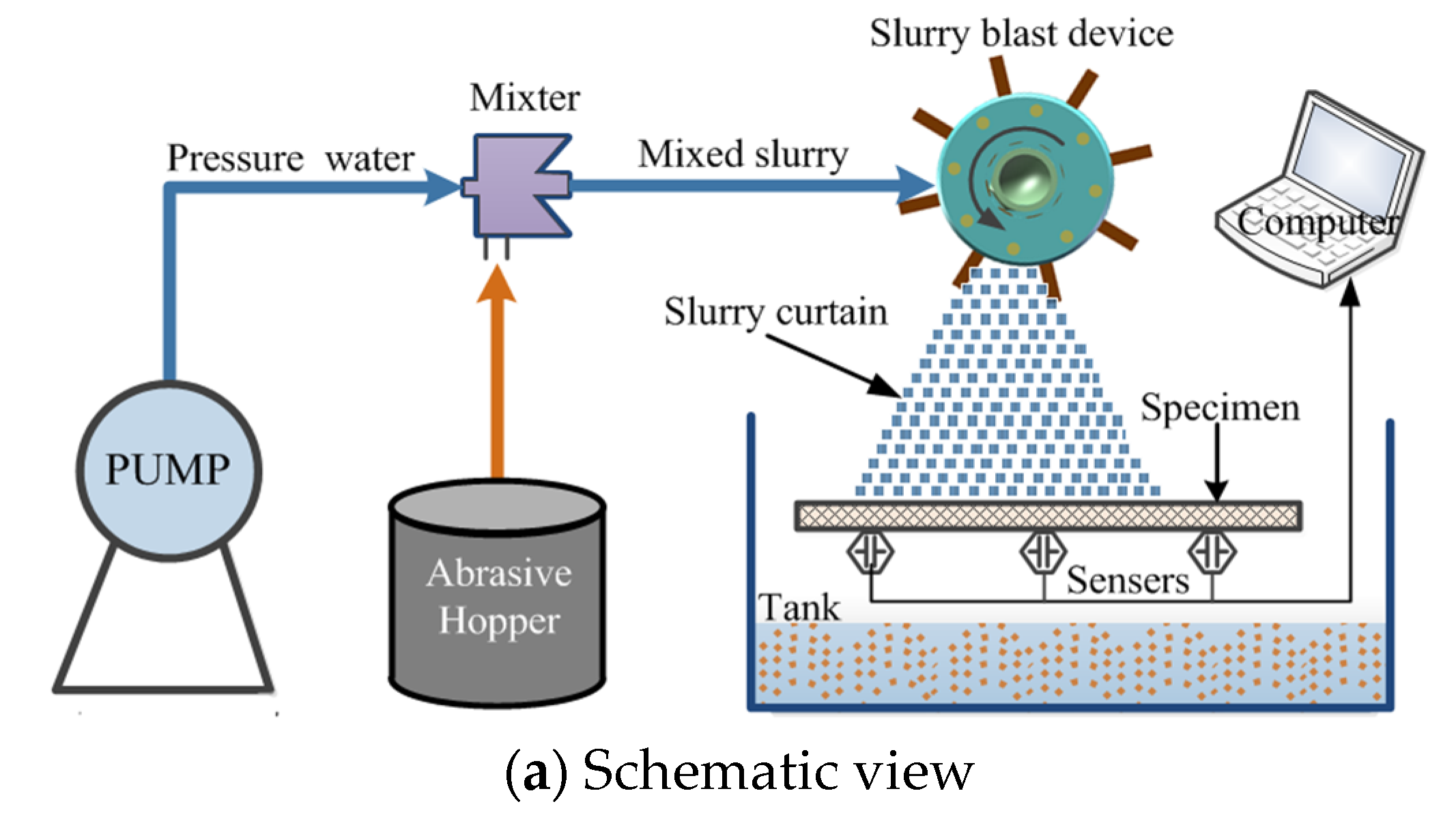
Figure 1 shows the 3D structure of the slurry blast device, which is mainly composed of a mixed slurry inlet, directional cover, slurry jet outlet, driving hub, rotating blades, and auxiliary accessories. During the operation of the slurry blast device, high-pressure water first flows into a self-excited oscillating mixer, where abrasive particles and high-pressure water are mixed [17]. Then, the mixed slurry is injected into the blades through the liquid inlet pipe to impact the surface of the steel strip under the acceleration of the high-speed rotating blade driven by an electric motor. The main role of water is primarily to accelerate large quantities of abrasive particles to a high velocity and to produce a highly coherent jet (i.e., mixed slurry jet) to impact the surface of the steel plate.

2.2. Materials and Test Methods

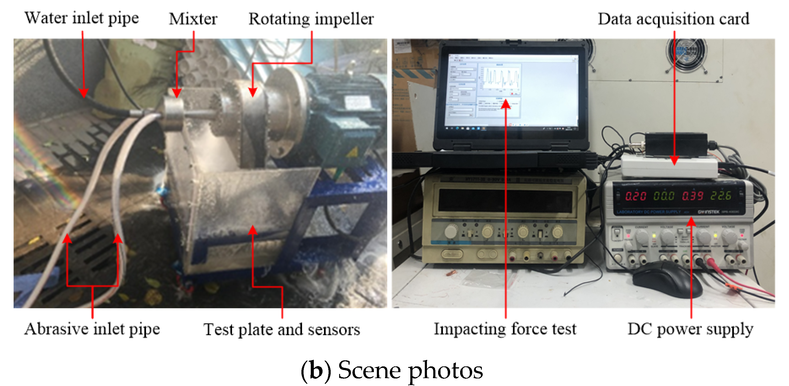
Figure 2 shows the schematic view of the experimental setup, which is mainly composed of a water hydraulic control system, slurry mixer, slurry blast device, and data acquisition device. Here Rated flow and pressure of the pump is 120 L/min, 14 MPa, respectively. The high-pressure water and the abrasive are uniformly mixed and accelerated by the mixer, and then the mixed slurry enters the slurry blast device. Under the centrifugal acceleration of the rotating blades driven by the electric motor, the mixed slurry is sprayed to the sample plate (450 mm × 300 mm × 8 mm) at high speed to remove rust. The used abrasive is brown-fused alumina, which is angular and 3.0 g/cm3, and its mass flow rate is 0.2 kg/s. In the test, high-frequency pressure sensors (NOS-F306, 0–5 KN) installed under the test sample plate is to measure the impact force. After the test, the OHAUS EX10202ZH balance with an accuracy of 10 mg is used to measure the weight loss of the sample to estimate the quality of rust removal.

2.3. Mathematical Model

In this paper, mixed slurry refers to slurry composed of liquid and particles in a certain proportion, and the particles in the slurry move with the movement of the liquid. The multiphase Eulerian model is used to simulate the flow characteristics of the mixed slurry. Given that the multiphase Euler model does not allow inviscid flow, volume fraction represents the space occupied by each phase, and each phase satisfies the law of conservation of mass and momentum [12].
The volume V δ of phase δ is defined by
V δ = V α δ d V ,
where
δ = 1 n α δ = 1
The effective density of phase δ is
ρ ^ δ = α δ ρ δ ,
where ρ δ is the physical density of phase δ .
The volume fraction of each phase is calculated from a continuity equation.
1 ρ r q { t ( α q ρ q ) + ( α q ρ q v q ) = p = 1 n ( m ˙ p q m ˙ q p ) = 0 } ,
where v q is the velocity of fluid phase q, m ˙ p q characterizes the mass transfer from the solid phase p to fluid phase q, and m ˙ q p characterizes the mass transfer from phase q to phase p.
The conservation of momentum for phase q is
t ( α q ρ q v q ) + ( α q ρ q v q v q ) = p = 1 n ( R p q ( v p v q ) + m ˙ p q v p q m ˙ q p v q p ) α q p + τ q + α q ρ q g + ( F q + F l i f t , q + F w l , q + F v m , q + F t d , q )
where τ p is the stress–strain tensor of p, which can be expressed as
τ p = α p μ p ( v p + v p T ) + α p ( λ p 2 3 μ p ) v p I ,
here μ p and λ p are the shear and the bulk viscosity of the phase, respectively; p is the pressure shared by all phases; Rpq is the momentum exchange coefficient between the fluid phase q and solid phase p; n is the total number of phases. F q is an external body force, F l i f t , q is a lift force, F w l , q is a wall lubrication force, F v m , q is a virtual mass force, and F t d , q is a turbulent dispersion force.
Erosion wear means that abrasive particles have a certain kinetic energy after being accelerated by high-pressure water, and high-velocity abrasive particles affect the damage on the surface of the object, making its surface rust peel off [23]. In ANSYS Fluent, particle erosion can be monitored at wall boundaries and is defined as the material mass removed/(area-time). Erosion rate is defined as [19]
R e r o s i o n = p = 1 N p a r t i c l e m ˙ p C ( d p ) f ( θ ) ν b ( ν ) A f a c e ,
where m ˙ p is the mass flow rate of the particles; C(dp) and b(v) are the functions of particle diameter and particle relative velocity, respectively; θ is the impact angle, v is the particle relative velocity, and A f a c e is the area of the wall.
The impact angle function f ( θ ) for steel being eroded by abrasive particles can be approximated by a piecewise-polynomial fit as [24,25]
f ( θ ) = { 0 + 22.7 θ 38.4 θ 2 θ 0.267 r a d 2.00 + 6.80 θ 7.5 θ 2 + 2.25 θ 3 θ > 0.267 r a d
The related parameters C(dp) and A f a c e defined by Fluent in this simulation work are 0.3–0.7 mm and 3 × 10⁻³ m2, respectively. When the impact angle θ changes from π / 3 to π / 2 , the value of the impact angle function f ( θ ) is 0.92–2.55.
This simulation work involves the application of rotating sliding meshes. Thus, the realizable k-ε model is selected as the viscous model. Turbulence energy k and dissipation rate ε in the realizable k-ε model can be presented as [25]
t ( ρ k ) + x j ( ρ k u j ) = x j [ ( μ + μ t σ k ) k x j ] + G k ρ ε + S k ,
t ( ρ ε ) + x j ( ρ ε u j ) = x j [ ( μ + μ t σ ε ) ε x j ] + ρ C 1 S ε ρ C 2 ε 2 k + v ε + S ε ,
μ t = ρ C μ k 2 ε ,   C 1 = max [ 0.43 , η η + 5 ] ,   η = S k ε ,   S = 2 S i j S i j ,   S i j = 1 2 ( μ j x i + μ i x j ) ,
where μ t is a function of the mean strain and rotation rates; u j represents the velocities in the x j coordinate directions; C 1 and C 2 are constants; σ k and σ ε are the turbulent Prandtl numbers for k and ε, respectively; ρ and µ are as defined earlier; S k and S ε are user-defined source terms. The model constants have the following default values [17]: C 1 = 1.44, C 2 = 1.92, σ k = 1.0, and σ ε = 1.3.

2.4. Grid Generation and Boundary Conditions

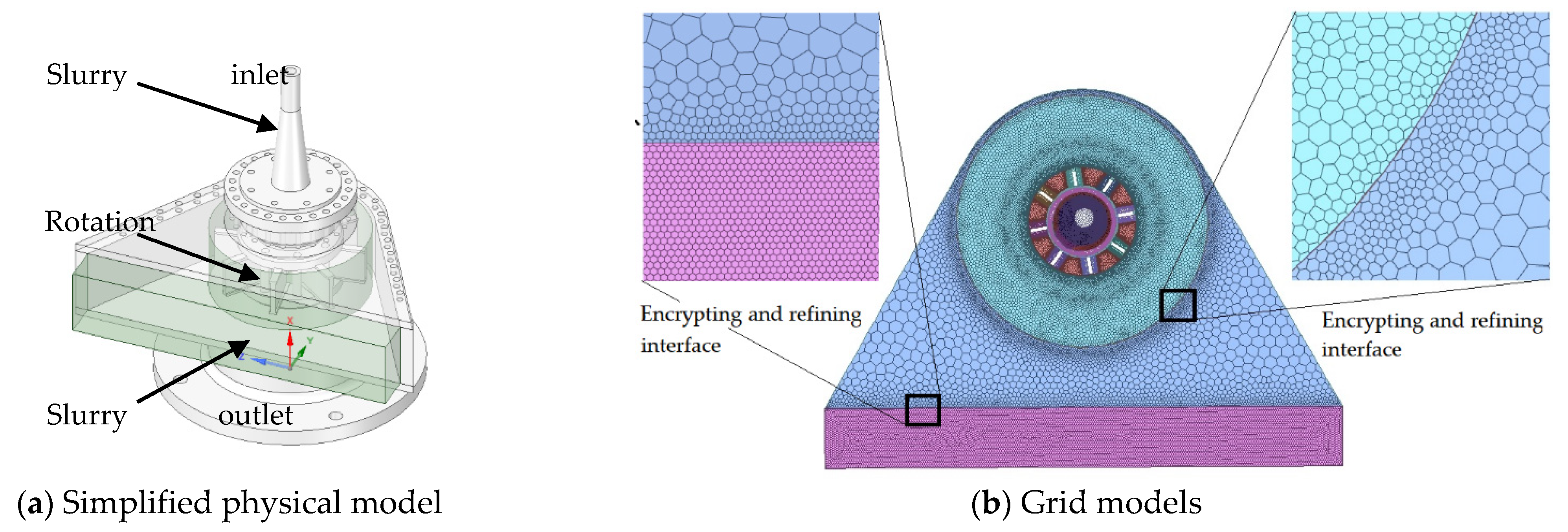
The 3D simplified model of the slurry blast device is shown in Figure 2a. It is established in the preprocessing software and simplified to remove details such as the gap that does not affect the simulation analysis. The fluid domain consists of three parts: inlet domain, rotation domain, and outlet domain. The CFD simulation starts from the inlet domain, goes through the boundary of the interface into the rotation domain, and ends after the outlet domain.
Considering that the hexahedral grid can better meet the fluid flow direction and the grid accuracy and calculation speed are high, the hexahedral grid is used as the grid element. In addition, the local unstructured mesh refinement based on a high-speed gradient is explored to solve the very large flow gradient in the turning region. After encrypting and refining the local area, especially the interface area, the mesh model is shown in Figure 3b. Here taking the simulation variation of erosion rate and particle velocity as a reference, grid independence is tested to select the appropriate grid accuracy (as shown in Table 1).
It can be seen from Table 1 the comparison of the calculation results of five different numbers of cells. The results show that with the increase in the number of cells, erosion rate and particle velocity increase first and then stabilize. The variation rate from Case 1 to Case 3 is relatively large, whereas that between Case 3 and Case 5 is less than 1%, which is almost unchanged. Therefore, considering the accuracy of the simulation results and the calculation speed, the grid generation method in Case 3 is adopted in the subsequent simulation.
Here a multiphase model in the CFD simulation consisting of a two-phase flow (water and particles) is established; water is the first phase, and particles are the second phase. The inlet of the model is set as the pressure inlet. Sliding grids are used in the rotation domain. The liquid phase satisfies the nonslip condition of the wall, and the particle phase satisfies the wall slip condition. The outlet is set as atmospheric pressure. The simulation parameters are shown in Table 2.

3. Results Analysis and Discussion

The finite volume method is employed to simulate the rotating flow field inside the slurry blast device, and a simple algorithm is used to solve the model. In this simulation, the DPM is adopted to track particle trajectory and velocity distribution, and the erosion model is used to simulate the erosion rate of mixed slurry on the steel plate. The effects of different parameters on the flow field characteristics and the rust removal efficiency of slurry blast devices are further discussed.

3.1. Simulation Results and Analysis

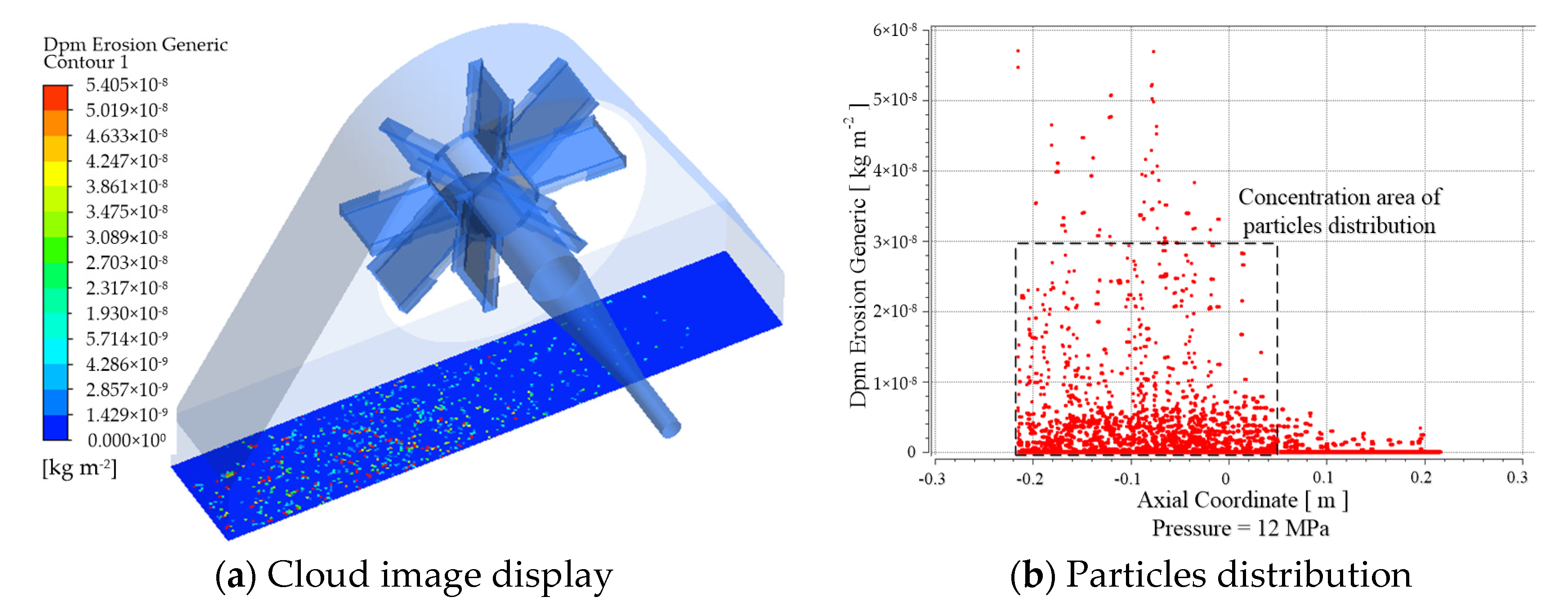
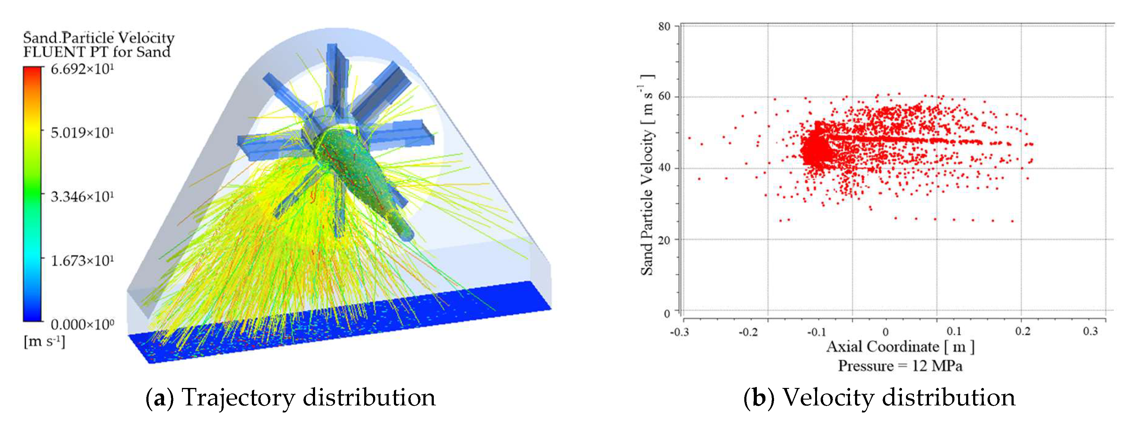
Setting the entrance pressure as 12 MPa, and the rotating speed of blades as 1000 rpm, CFD simulations of the jet flow field in slurry blast devices are carried out to study the particle distribution rule and erosion rate of mixed slurry. Several representative simulation results are shown in Figure 4, Figure 5 and Figure 6. The simulation time is approximately 0.35 s, and 15,340 particles are observed.
Figure 4a reveals that erosion locations are concentrated on the downwind area of the rotating blades on the steel plate. The erosion rate can reach 5.405 × 10⁻⁸ kg/m2, and the erosion range is relatively uniform, whereas the upwind area of the rotating blades on the steel plate has a relatively minimal erosion effect. The effective area of the rotating blade centrifugal jet is closely related to the relative position of the steel plate. Figure 4b shows the erosion rates and distribution areas of all particles. The erosion locations are concentrated on the downwind area of the rotating blades on the steel plate, and the erosion rate values are mostly concentrated in the range of 0–3.0 × 10⁻⁸ kg/m2. The average erosion rate of 15,340 dispersed particles is 2.345 × 10⁻⁸ kg/m2. According to Equation (7), the mass of the rust layer removed is 6.21 g/s.
Studying particle velocity distribution is necessary because particle velocity is a key parameter affecting erosion rate [26]. Figure 5 shows that when inlet velocity is 50 m/s, particle velocity is reduced to 30 m/s after entering the inlet pipe throat because the particles impacting the wall reflected, impact reflection causes energy loss, and then velocity is decreased. After passing through the elbow, the particles enter the blades of the slurry blast device. Driven by rotation blades, particle velocity is increased to approximately 67 m/s. Figure 5b shows the velocity distribution of 15,340 particles, and most of the particle velocities are between 35 m/s to 60 m/s, and their average speed is 55 m/s.
Figure 6a reveals that the highest water velocity is approximately 28 m/s, which is different from the particle velocity. Water flow is mainly concentrated in the middle and the upwind areas of the rotating blades on the strip, which is also different from the erosion of particles. This finding is mainly due to the dissimilar mass densities of water and particles, resulting in different velocities after the blade accelerates. In addition, a flow vortex is formed on the downwind area of the rotating blades on the strip, as shown in Figure 6b, and this is caused by the reflection of high-velocity water impacting the strip.
According to Equation (7) of the erosion rate, the jet velocity of the rotating blade centrifugal jet is the key factor affecting its numerical value. However, jet velocity mainly depends on inlet pressure and blade rotation speed. In addition, particle diameter may also influence the erosion effect of the rotating blade centrifugal jet. Therefore, studying the influence of these three parameters on the jet velocity of the rotating blade centrifugal jet is essential.

3.2. Effect of Different Inlet Pressures

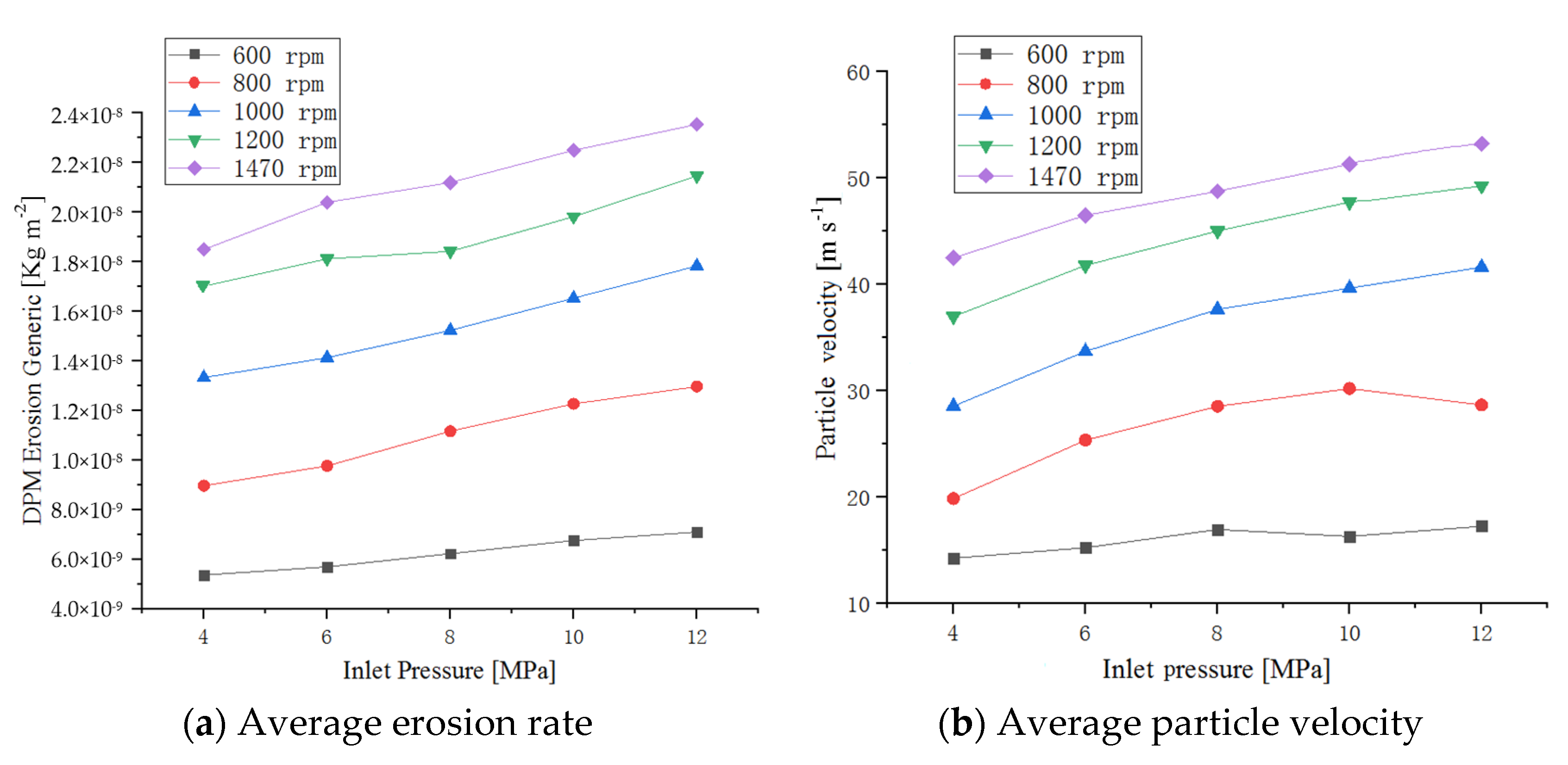
To investigate the effect of inlet pressure on the rotating blade centrifugal jet characteristics, the inlet pressures of 4, 6, 8, 10, and 12 MPa is assumed. The particle diameter is 0.4 mm, and the average erosion rate and particle velocity with inlet pressure under different blade rotation speeds are shown in Figure 7.
Figure 7a shows that the erosion rate increases slowly with the increase in inlet pressure. When blade rotation speed is 1470 rpm, the erosion rate at 12 MPa is approximately 1.24 times that at 4 MPa. Figure 7b shows the variation trend of abrasive velocity is the same as that of the erosion rate in Figure 7a. When blade rotation speed is 1470 rpm, the particle velocity at 12 MPa is approximately 1.28 times that at 4 MPa. However, the increase in system pressure causes a sharp increase in the operating cost of the slurry blast device and may reduce its service life and reliability. Therefore, selecting a reasonable pressure is helpful to improving the rust removal of the slurry blast device economically and efficiently.

3.3. Effect of Different Blade Rotation Speeds

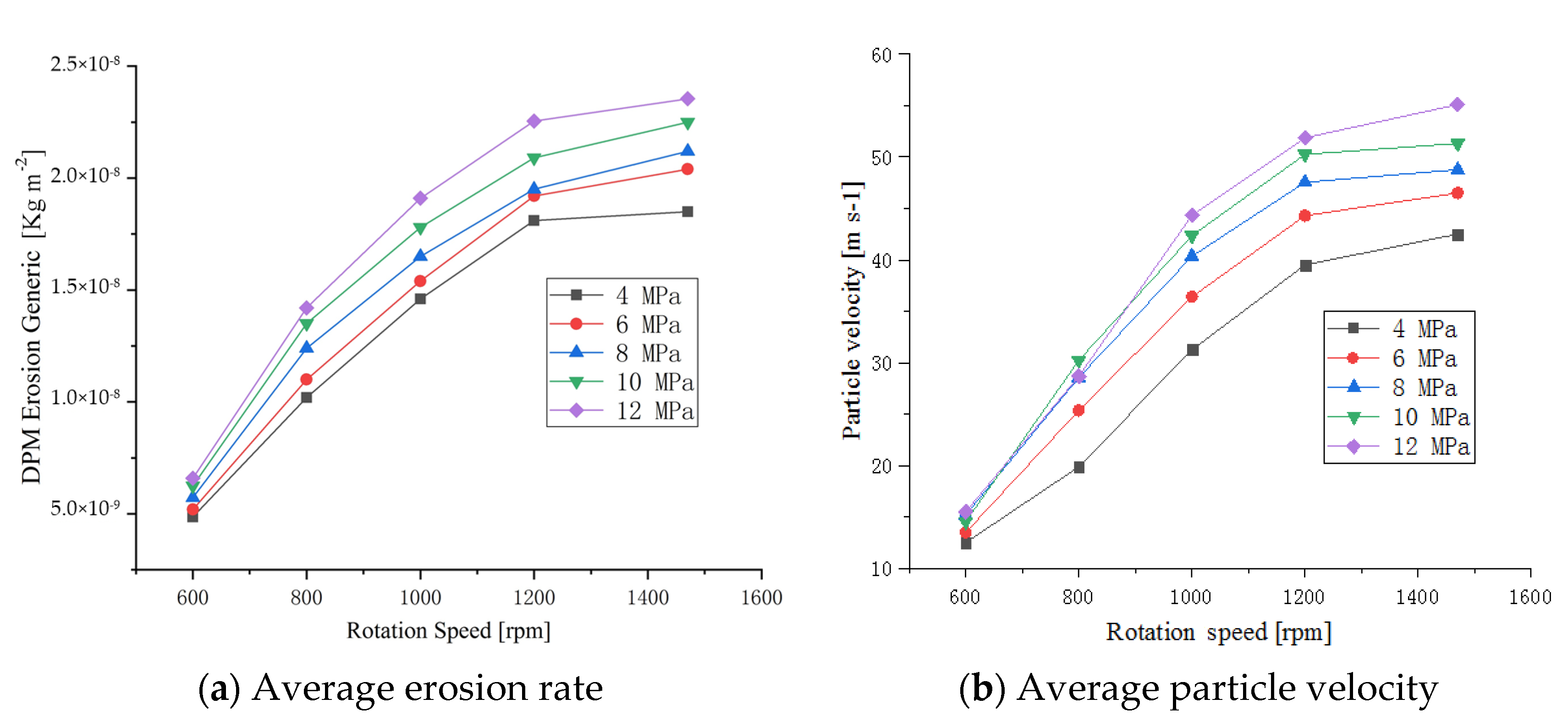
For the jet flow field of the slurry blast device, rotation speed mainly affects the velocity of the rotating blade centrifugal jet and the distribution position of the rust removal, which is an important factor of the rust removal effect. When the impeller speeds are 600, 800, 1000, 1200, 1470 rpm and the particle diameter is 0.4 mm, the average erosion rate and particle velocity under different system pressures are shown in Figure 8.
Figure 8a shows that the erosion rate increases sharply with the increase in blade rotation speed. When pressure is 12 MPa, the erosion rate at 1470 rpm is approximately 3.6 times that at 600 rpm. The variation trend of abrasive velocity in Figure 8b is consistent with that of the erosion rate in Figure 8a. When pressure is 12 MPa, the particle velocity at 1470 rpm is approximately 3.4 times that at 600 rpm. Compared with the effect of inlet pressure, the variation of rotation speed has more effect on the variation of these two parameters. In this equipment, the rated speed of the motor is 1470 rpm. The higher the rotation speed is, the more energy is consumed. The influences of rotation speed on equipment performance and distribution position of the rust removal should be considered comprehensively.

3.4. Effect of Different Particle Diameters

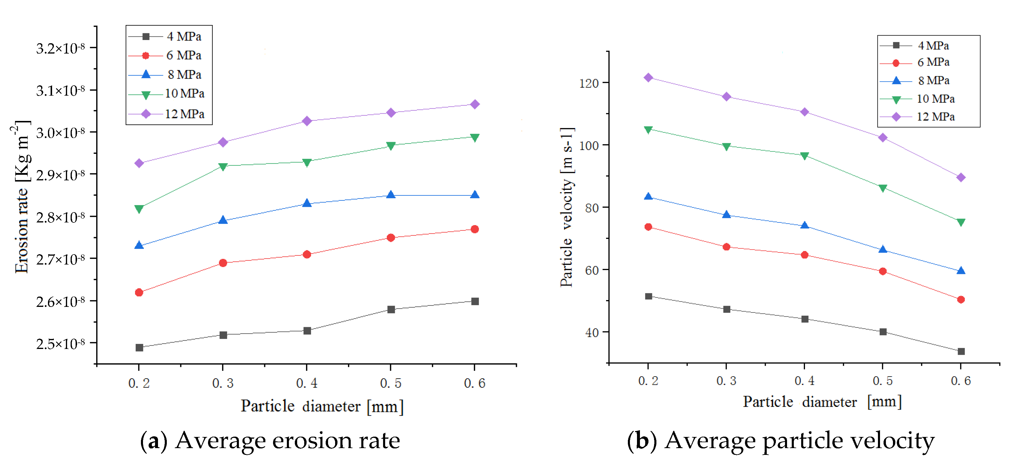
Assuming that the particles are spherical, the particle diameters are set to 0.2, 0.3, 0.4, 0.5 and 0.6 mm, respectively, the system pressure to 10 MPa, and the impeller speed to 1000 rpm. The average erosion rate and particle velocity under different system pressures are shown in Figure 9.
Figure 9a shows that the variation of erosion rate is positively related to the variation of particle diameter. Figure 9b shows that particle velocity is inversely proportional to particle diameter, and smaller particles decelerate more quickly than larger particles. Because the ratio of viscous force to inertia force decreases with the increase in particle diameter. Small particles have less mass and less momentum, and then their velocity decays more quickly [17]. Clearly, on the premise that the rust layer of the steel plate can be completely removed, the smaller particle is an effective method to improve the particle velocity and the rust removal ability of the rotating blade centrifugal jet.

4. Experiment Verification

The developed slurry blast descaling experimental system is used for the selection of control parameters and the optimization of their influence on the rust removal performance of steel plates through slurry blast devices. For the present experiment, the influence of variable parameters (inlet pressure and rotation speed) on the rust removal effect is studied to verify the correctness of the previous CFD simulation model and further check the reliability of other parameters in the simulation results. The rust removal effect of the slurry blast device is also investigated in detail.

4.1. Impact Force at Different Blade Rotation Speeds

According to the law of conservation of momentum and assuming that the velocity before impingement is identical to that after reflection, the impact force of jet can be presented as
F s = ρ ¯ s q s v ¯ s ( 1 cos θ ) ,
v ¯ s = F s / ρ ¯ s q s ( 1 cos β ) , ρ ¯ s = 0.9 ρ w + 0.1 ρ p ,
where Fs is the impact force of jet; ρ ¯ s and v ¯ s are the mixed slurry average density and velocity, respectively; q s is jet volume flow; θ is jet impact angle; ρ w and ρ p are the density of water and abrasive, respectively.
Here the system pressure was set to 10 MPa, the diameter of abrasive particles was set to 0.4 mm, and the rotation speed of the blade was set to 600, 800, 1000, 1200, and 1470 rpm. According to Equation (13), the rotating blade centrifugal jet velocity obtained from the previous simulation under different blade rotation speeds is converted into impact force, as shown in Table 3.
Figure 10 reveals the variation trend of the impact force measured by the test is consistent with the simulation, and the impact force at 1470 rpm is approximately 3.4 times that at 600 rpm. However, the impact force obtained from the test is relatively small, which is approximately 80% of the simulated impact force. According to the reference [27], the experimental impact force is 0.6–0.85 times the theoretical impact force. In this study, the impact force measured in the experiment is approximately 0.8 times that in the simulation. Therefore, the simulation method used in this paper is effective.

4.2. Weight of Rust Removed at Different Blade Rotation Speeds

According to the erosion rate illustrated in Equation (7), the weight of rust removed in simulation step time can be described as
M r u s t = R e r o s i o n A f a c e N p a r t i c l e / T s t e p ,
where N p a r t i c l e is the number of particles, and T s t e p is the simulation step time. In this paper, the effective erosion area of specimen A f a c e = 450 mm × 40 mm = 18,000 mm2.
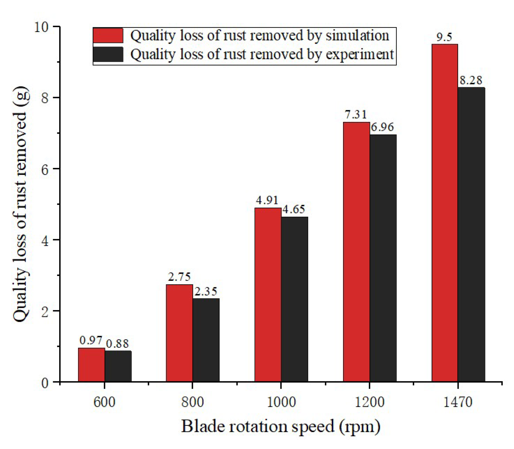
Figure 11 shows the comparison of the specimen morphology before and after rust removal. The weight of rust removed in each test can be obtained by comparing the weight of the specimens before and after the test. The weight of rust removed by simulation and experiment under different blade rotation speeds are shown in Table 4.
Figure 12 compares the weight of rust removal by simulation calculation and experimental measurement at different blade speeds. The weight of rust removed is proportional to the blade rotation speed, and the maximum value reaches 9.5 g/s when the rotation speed is 1470 rpm. The experimental data are consistent with the simulation trend, which is approximately 85–95% of the simulation value. The error may be due to two reasons: First, the velocity of the jet acting on the specimen surface is smaller than the theoretical velocity due to jet diffusion and air resistance. Second, although the specimens are taken from the same steel plate, the degree of the rust is inevitably different, which affects the measurement of the rust and brings errors. Generally, it is consistent with the trend of simulation data, and the error is within the acceptable range [28]. Therefore, the experimental and simulation methods are feasible for studying the performance of slurry blast rust removal.

4.3. Impact Force at Different Inlet Pressures

The rotation speed of the blade was set to 1470 rpm, the abrasive particle diameter was set to 0.4 mm, and the system pressure was set to 4, 6, 8, 10, and 12 MPa. The experiment was repeated five times for each pressure parameter, and the impact force of each experiment was measured with a pressure sensor. According to Equation (7), combined with the simulation results of different inlet pressures in Figure 6, after calculation and experimental measurement, the average value of five impact forces is shown in Table 5. It can be seen that the variation trend of the impact force measured by the test is the same as the simulation. With the increase in pressure, the impact force at 12 MPa is approximately 1.28 times that at 4 MPa. However, the impact force obtained from the test is relatively less, approximately 80% of the simulated impact force. This finding is due to the impact of jet diffusion and air resistance, and the impact force of the jet on the surface of the object is smaller than the theoretical impact. The comparison result is the same as the comparison result at different blade rotation speeds. Compared with the conclusions of relevant literature [26], the simulation and experimental methods in this paper can be considered feasible.

5. Conclusions

Slurry blast rust removal technology is a green production technology used for mechanically removing oxide scale on the surface of steel strips, which can avoid the serious problems of rapid wear, low service life, and low efficiency of the traditional AWJ nozzles in the field of steel strip descaling. The DPM and the erosion model are innovatively applied to simulate the movement characteristics of particles inside the rotating blade centrifugal jet and to study the influence of important system parameters on the flow field characteristics of the rotating jet. The effects of blade rotation speed and inlet pressure on descaling efficiency are investigated experimentally and compared with the simulation results. According to the simulation and experimental results, the following points could be concluded.
(1)
The DPM is adopted to simulate the momentum and the energy of particles in a continuous phase and then obtain trajectory and particle velocity. The erosion model can simulate the erosion effect of particles on the rust layer and removal weight changes with time. The simulation results show that erosion locations are concentrated on the downwind area of the rotating blades on the steel plate, and erosion rates are mostly in the range of 0–3.0 × 10⁻⁸ kg/m2.
(2)
The erosion rate and the particle velocity of the mixed slurry are proportional to blade rotation speed and inlet pressure. Impact force is increased by 3.4 times with the variation of different blade rotation speeds and is increased by 1.28 times with the increase in inlet pressure. Therefore, the larger blade rotation speed and reasonable inlet pressure should be adopted as much as possible to obtain a greater impact force and improve the efficiency of rust removal of slurry blast devices.
(3)
The abrasive particle diameter has a minimal effect on erosion rate, and particle velocity decreases with the increase in particle diameter distinctly. Assuming that the rust layer of the steel plate can be completely removed, the smaller particle is an effective method to improve the particle velocity and the rust removal ability of the rotating blade centrifugal jet.
(4)
The weight of rust removed is proportional to blade rotation speed. When the rotation speed is 1470 rpm, the maximum weight of rust removed reaches 9.5 g/s. The experimental data are consistent with the simulation trends, which are approximately 85–95% of the simulation value.
This paper will play remarkable guiding roles in the engineering optimization of slurry blast devices for steel strip descaling and the application to the surface treatment of other metal structures.

6. Patents

The national patents:
(1)
Nie, S.; Huo, G.; Ji, H. A High Pressure Water Mixed Steel Strip Rust Removal Device: China. ZL 201810423430.2 [P], 13 December 2019 (authorized).
(2)
Nie, S.; Huo, G.; Ji, H. A Blade Type Slurry Blast Device for Strip Steel Cleaning: China. ZL 201810423429.x [P], 28 August 2020 (Authorized).

Author Contributions

Writing—original draft, conceptualization, methodology, data curation, G.H.; conceptualization, methodology, investigation, funding acquisition, Z.M.; writing—review and editing, conceptualization, investigation, formal analysis, Y.H.; writing—review and editing, methodology, conceptualization, supervision, S.N.; conceptualization, investigation, methodology, formal analysis, Z.Z. All authors have read and agreed to the published version of the manuscript.

Funding

This research was funded by the National Natural Science Foundation of China (Grant Nos. 51975010, 51905011, 52005468), Beijing Natural Science Foundation (Grant No. 3202035), General Program of Science and Technology Development Project of Beijing Municipal Education Commission (Grant Nos. KM201910005033 and KM202110005031).

Institutional Review Board Statement

Not applicable.

Informed Consent Statement

Not applicable.

Data Availability Statement

Not applicable.

Conflicts of Interest

The authors declare no conflict of interest.

References

  1. Zieliński, A.; Dudziak, T.P.; Golański, G.; Gazdowicz, J.; Koodziej, A. Effects of long-term ageing at high temperatures on oxide scale development and evolution of austenitic steels microstructure. Steel Res. Int. 2020, 91, 1900595. [Google Scholar] [CrossRef]
  2. Bhattacharya, R.; Jha, G.; Kundu, S.; Shankar, R.; Gope, N. Influence of cooling rate on the structure and formation of oxide scale in low carbon steel wire rods during hot rolling. Surf. Coat. Technol. 2006, 201, 526–532. [Google Scholar] [CrossRef]
  3. Bourithis, L.; Papadimitriou, G. Three body abrasion wear of low carbon steel modified surfaces. Wear 2005, 258, 1775–1786. [Google Scholar] [CrossRef]
  4. Hlavá, L.M.; Hlaváová Planár, I.M.; Krenick, T.; Geryk, V. Deformation of products cut on AWJ x-y tables and its suppression. IOP Conf. Ser. Mater. Sci. Eng. 2018, 307, 12015. [Google Scholar] [CrossRef]
  5. Monno, M.; Ravasio, C. The effect of cutting head vibrations on the surfaces generated by waterjet cutting. Int. J. Mach. Tools Manuf. 2005, 45, 355–363. [Google Scholar] [CrossRef]
  6. Minakov, V.V. New technologies for cleaning up oil spills. Chem. Pet. Eng. 2004, 40, 59–62. [Google Scholar] [CrossRef]
  7. Leu, M.C.; Meng, P.; Geskin, E.S.; Tismeneskiy, L. Mathematical modeling and experimental verification of stationary waterjet cleaning process. J. Manuf. Sci. Eng. 1998, 120, 571–579. [Google Scholar] [CrossRef]
  8. Anand, U.; Katz, J. Prevention of nozzle wear in abrasive water suspension jets (AWSJ) using porous lubricated nozzles. J. Tribol. 2003, 125, 168–180. [Google Scholar] [CrossRef]
  9. Chen, X.; Deng, S.; Guan, J.; Hua, W. Experiment and simulation research on abrasive water jet nozzle wear behavior and anti-wear structural improvement. J. Braz. Soc. Mech. Sci. Eng. 2017, 39, 1–11. [Google Scholar] [CrossRef]
  10. Li, B. A review of tool wear estimation using theoretical analysis and numerical simulation technologies. Int. J. Refract. Met. Hard Mater. 2012, 35, 143–151. [Google Scholar] [CrossRef]
  11. Deng, D.; Murakawa, H.; Shibahara, M. Investigations on welding distortion in an asymmetrical curved block by means of numerical simulation technology and experimental method. Comput. Mater. Sci. 2010, 48, 187–194. [Google Scholar] [CrossRef]
  12. Andreini, A.; Bianchini, C.; Puggelli, S.; Demoulin, F.X. Development of a turbulent liquid flux model for Eulerian-Eulerian multiphase flow simulations. Int. J. Multiph. Flow 2016, 81, 88–103. [Google Scholar] [CrossRef]
  13. Zeng, Y.C.; Yu, C.W. Numerical simulation of air flow in the nozzle of an air-jet spinning machine. Text. Res. J. 2003, 73, 350–356. [Google Scholar] [CrossRef]
  14. Annoni, M.; Arleo, F.; Malmassari, C. CFD aided design and experimental validation of an innovative air assisted pure water jet cutting system. J. Mater. Processing Technol. 2014, 214, 1647–1657. [Google Scholar] [CrossRef] [Green Version]
  15. Guha, A.; Barron, R.M.; Balachandar, R. Numerical simulation of high-speed turbulent water jets in air. J. Hydraul. Res. 2010, 48, 119–124. [Google Scholar] [CrossRef]
  16. Liu, H.; Wang, J.; Kelson, N.; Brown, R.J. A study of abrasive waterjet characteristics by CFD simulation. J. Mater. Processing Technol. 2004, 153–154, 488–493. [Google Scholar] [CrossRef] [Green Version]
  17. Ji, H.; Cao, X.R.; Nie, S.L.; Yin, F.L. Simulation and experiment study of the self-excited oscillating mixer with abrasive jet used for the descaling of rusty steel. Proc. Inst. Mech. Eng. Part E J. Process Mech. Eng. 2019, 233, 1109–1127. [Google Scholar] [CrossRef]
  18. Chattopadhyay, K.; Isac, M.; Guthrie, R.I.L. Considerations in using the discrete phase model (DPM). Steel Res. Int. 2011, 82, 1287–1289. [Google Scholar] [CrossRef]
  19. Safaei, M.R.; Mahian, O.; Garoosi, F.; Hooman, K.; Karimipour, A.; Kazi, S.N.; Gharehkhani, S. Investigation of micro- and nanosized particle erosion in a 90° pipe bend using a two-phase discrete phase model. Sci. World J. 2014, 2014, 1–12. [Google Scholar] [CrossRef] [Green Version]
  20. Mezhericher, M.; Brosh, T.; Levy, A. Modeling of particle pneumatic conveying using DEM and DPM methods. Part. Sci. Technol. 2011, 29, 197–208. [Google Scholar] [CrossRef]
  21. Moslemi, A.; Ahmadi, G. Study of the hydraulic performance of drill bits using a computational particle-tracking method. SPE Drill. Completion 2014, 29, 28–35. [Google Scholar] [CrossRef]
  22. Saman, R.; Javad, E.; Rahmat, E. Convective heat transfer and particle motion in an obstructed duct with two side by side obstacles by means of DPM model. Appl. Sci. 2017, 7, 431. [Google Scholar]
  23. Jeon, S.; Kim, Y. Numerical simulation of level ice-structure interaction using damage-based erosion model. Ocean. Eng. 2020, 220, 108485. [Google Scholar] [CrossRef]
  24. Nugroho, S.S.; McLaury, B.S.; Shirazi, S.A. Application of a CFD-Based Erosion Prediction Procedure for Sudden Expansions; Volume 2: Symposia and General Papers, Parts A and B; ASME: Montreal, QC, Canada, 2002. [Google Scholar]
  25. Chen, X.; McLaury, B.S.; Shirazi, S.A. Application and experimental validation of a computational fluid dynamics (CFD)-based erosion prediction model in elbows and plugged tees. Comput. Fluids 2004, 33, 1251–1272. [Google Scholar] [CrossRef]
  26. Tazibt, A.; Parsy, F.; Abriak, N. Theoretical analysis of the particle acceleration process in abrasive water jet cutting. Comput. Mater. Sci. 1996, 5, 243–254. [Google Scholar] [CrossRef]
  27. Summers, D.A. Waterjetting Technology; Taylor and Francis: London, UK, 1995; ISBN 0419196609. [Google Scholar]
  28. Mansouri, A.; Arabnejad, H.; Shirazi, S.A.; McLaury, B.S. A combined CFD/experimental methodology for erosion prediction. Wear 2015, 332–333, 1090–1097. [Google Scholar] [CrossRef]
Figure 1. Physical models of the slurry blast device.
Applsci 12 00478 g001
Figure 2. Developed slurry blast descaling experimental system.
Applsci 12 00478 g002aApplsci 12 00478 g002b
Figure 3. Models of the slurry blast device.
Applsci 12 00478 g003
Figure 4. DPM erosion rate of abrasive particles.
Applsci 12 00478 g004
Figure 5. Trajectory and velocity distribution of abrasive particles.
Applsci 12 00478 g005
Figure 6. Velocity vector distribution and volume fraction of the water flows.
Applsci 12 00478 g006
Figure 7. Average erosion rate and particle velocity with inlet pressure at different blade rotation speeds.
Applsci 12 00478 g007
Figure 8. Average erosion rate and particle velocity with rotation speed at different inlet pressures.
Applsci 12 00478 g008
Figure 9. Average erosion rate and particle velocity with particle diameter at different inlet pressures.
Applsci 12 00478 g009
Figure 10. Impact force comparison between simulation and experiment at different blade rotation speed.
Applsci 12 00478 g010
Figure 11. Comparison of the specimen morphology before and after rust removal.
Applsci 12 00478 g011
Figure 12. Weight of rust removed between simulation and experiment at different blade rotation speed.
Applsci 12 00478 g012
Table 1. Grid independence test of different number of cells.
No.Number of CellsErosion Rate (kg/m2)Particle Velocity(m/s)
Case 1874,0502.33 × 10−848.51
Case 21,206,4822.55 × 10−853.25
Case 31,543,3652.61 × 10−855.12
Case 41,769,1182.62 × 10−855.40
Case 52,685,2202.626 × 10−855.52
Table 2. Basic parameters of CFD simulation for the slurry blast device.
ParametersUnitValue
Water/Abrasive densitykg/m3998.2/3000
Water viscositykg/(m3/s)0.001003
Percent of abrasive%10
Abrasive diametermm0.2/0.3/0.4/0.5/0.6
Total flow rate of abrasivekg/s0.2
Blade rotation speedrpm600/800/1000/1200/1470
Inlet pressureMPa4/6/8/10/12
Table 3. Impact forces at different blade rotation speed.
No.Blades Rotation Speed (rpm)Simulation Velocity (m/s)Simulation Impact Force (N)Experimental Impact Force (N)
160013.2441.2933.03
280027.6385.7655.74
3100038.52120.1984.14
4120045.21142.61106.95
5147048.78145.65116.52
Table 4. Weight of rust removed at different blade rotation speed.
No.Blade Rotation Speed (rpm)Average Erosion Rate (kg/m2)Number of the ParticlesWeight of Rust Removed by Simulation (g/s)Weight of Rust Removed by Experiment (g/s)
16006.25 × 10−993700.970.88
28001.35 × 10−811,3302.752.35
310001.78 × 10−815,3404.914.65
412002.09 × 10−819,4307.316.96
514702.25 × 10−823,4609.508.28
Table 5. Impact forces at different inlet pressure.
No.Inlet Pressure (MPa)Simulation Velocity (m/s)Simulation Impact Force (N)Experimental Impact Force (N)
1442.5120.62102.33
2646.5132.97112.17
3848.77138.41116.26
41051.32147.65122.43
51255.09153.35125.77
Publisher’s Note: MDPI stays neutral with regard to jurisdictional claims in published maps and institutional affiliations.