Abstract
Past studies on deep-lying tunnels under the assumption of plane strain have generally neglected the influence of intermediate principal stress even though this affects the surrounding rocks in the plastic zone. This study proposes a finite difference method to compute the stress strain plastic region and displacement of a tunnel based on the Drucker–Prager (D–P) yield criterion and non-associated flow rule and considering the influences of intermediate principal stress and the strain-softening behavior of surrounding rock. The computed results were compared with those of other well-known solutions and the accuracy and validity of the method were confirmed through some examples. Parameter analysis was conducted to investigate the effects of intermediate principal stress on stress-strain, the plastic region, the ground response curve, and the dilatability of surrounding rock. The results showed that the plastic radius , the residual radius , and radial displacement of surrounding rock first decreased and then increased with increasing intermediate principal stress coefficient b from 0 to 1, with the minimums occurring at b = 0.75. On the contrary, the peak and rate of variation of the dilatancy coefficient first increased and then decreased with increasing b and the dilatancy coefficient gradually transitioned from nonlinear to linear variation. Meanwhile, the inhibition of the plastic radius and radial displacement gradually weakened with increasing support pressure, whereas the dilatancy coefficient of the tunnel opening gradually increased.
1. Introduction
Underground tunnels dominate constructed underground structures in rock engineering and include highway and railway tunnels, underground workshops, mines, and hydraulic tunnels. Underground engineering results in the destruction of the original stress equilibrium state and in the redistribution of stress in the surrounding rock of the tunnel. This results in the formation of an area of increased stress, which can cause tunnel deformation and failure, and even rock burst [1,2,3]. Therefore, the accurate prediction of the distribution of stress, plastic radius, and displacement of the plastic zone of surrounding rock is of great significance and provides the basis for the analysis of the stability of surrounding rock. However, comparisons between experimental results and yield criteria-calculated stress state and plastic range of surrounding rock have indicated contradictions, with large discrepancies sometimes shown. Therefore, the selection of a suitable yield criterion can increase the accuracy of a calculated stress state.
Many recent studies have proposed analytical solutions for models of complete elasto-plasticity, elasto-brittleness, and strain-softening of surrounding rock using the Mohr–Coulomb (M–C) yield criterion or Hoek–Brown (H–B) yield criterion [4,5,6,7,8,9,10,11,12,13]. Although these studies are of practical and theoretical value, they do not consider the effect of intermediate principal stress on the deformation and failure resulting from tunnel excavation. However, both theory and practical observations indicate that most of the rock mass remains in a three-dimensional (3D) stress state after the tunnel excavation and unloading. Many studies, both theoretical and experimental [14,15,16], have shown that the strength of geotechnical materials is closely related to intermediate principal stress. Therefore, ignoring the effect of intermediate principal stress by rock mass strength can lead to deviations in engineering design. There is currently only a gradual application of strength criteria considering the influence of intermediate principal stresses within the study of surrounding rock of tunnels and related rock engineering. These applications mainly include the Drucker−Prager (DP) series strength criterion and the Unified Strength Theory (UST). Based on UST, Yu et al. [17] proposed that intermediate principal stress could be represented by a parameter b and the other two principal stresses in the plastic zone. However, this assumption lacks a strong theoretical basis. A study by Xu [18] that considered the effect of intermediate principal stress applied the unified strength theory of Yu et al. [17] to the calculation of a circular tunnel. Hou [19] applied the Levy–Mises constitutive relationship to deduced the expression of intermediate principal stress in the plastic zone as the average of the other two principal stresses. However, the Levy–Mises constitutive relationship for metallic materials is not suitable for geotechnical materials. Zhang Qiang et al. [20] applied the UST to study the effect of intermediate principal stress on the range of the fracture zone and deformation of the surrounding rock of a deeply buried tunnel. However, they did not provide a method for calculating intermediate principal stress. A finite difference method, which is used to calculate the strain-softening behavior of rock masses considering the effect of intermediate principal stress, has been proposed to calculate intermediate principal stress based on the unified failure criterion and non-flow associated flue [21]. However, the UST does not consider the influence of hydrostatic pressure on the deformation of surrounding rock and its complex form of expression is not convenient for application within engineering. The D–P criterion introduces the influence of intermediate principal stress, thereby providing a more practical solution to this kind of problem [22]. Therefore, the present study analyzed the effect of intermediate principal stress on the rock surrounding a tunnel using the D–P criterion.
The dilative angle ψ is generally used in elastoplastic analysis of deeply buried circular tunnels to express capacity expansion after unloading. Most current research on the shear dilative model has concentrated on the rock mass. In contrast, studies analyzing stresses of circular tunnels have mostly taken the dilative angle into account as a constant parameter or linear variable [5,23,24,25,26]. However, the dilative angle of rock mass cannot be considered a constant or linearly changing within practical engineering due to surrounding pressure and plastic shear strain. Detournay [3] proposed an attenuation model of the dilatancy coefficient for the surrounding rock of a circular tunnel. Subsequently, Alejano [13] proposed a nonlinear attenuation relationship between the dilatancy angle ψ and confining pressure based on the peak dilatancy function of the fractured rock mass. Zhao [26] found that the dilative angle of the rock mass presents a nonlinear relationship with the surrounding pressure and plastic shear strain.
The present study aimed to consider the softening properties of the rock mass and the effect of intermediate principal stress on the strength of the rock mass. The D–P criterion and non-correlated flow rule were applied to derive a finite difference numerical method as representative of the stress field, displacement field, and plastic radius of the surrounding rock under uniform stress. The influences of different factors on the stress, strain, deformation, and plastic range of surrounding rock were studied and compared with the solutions of the M–C and UST criterion. The results of the present study can provide a significant theoretical foundation for the assessment of stability and structural design of a deeply buried tunnel.
2. Description of the Problem
2.1. Theoretical Representation of a Tunnel Surrounded by Rock Mass
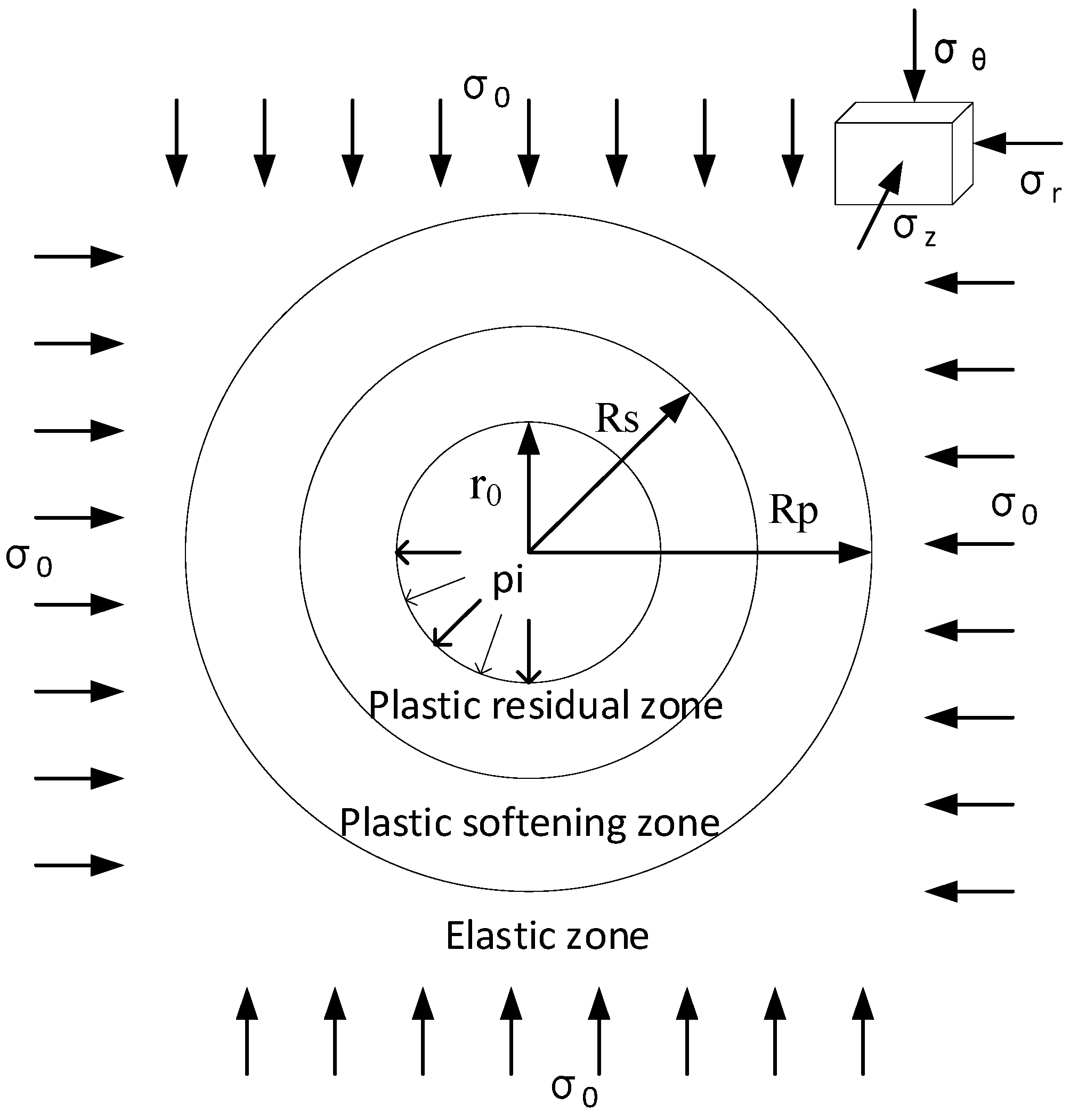
As shown in Figure 1, the excavation of a deeply buried tunnel with a cylindrical form is assumed as an axisymmetric plane strain problem by ignoring the influence of gravity and defining the principal stress outside the vertical section as the intermediate principal stress [1,27]. Assuming that the rock mass is homogeneous and isotropic, subject to the initial hydrostatic stress field of , the plastic region with radius is formed by the excavation of the tunnel with radius . The tunnel excavation surface is subject to a uniform distribution of support structure pressure pi, and and are the tangential stress and the radial stress in the elastic–plastic zone, respectively.
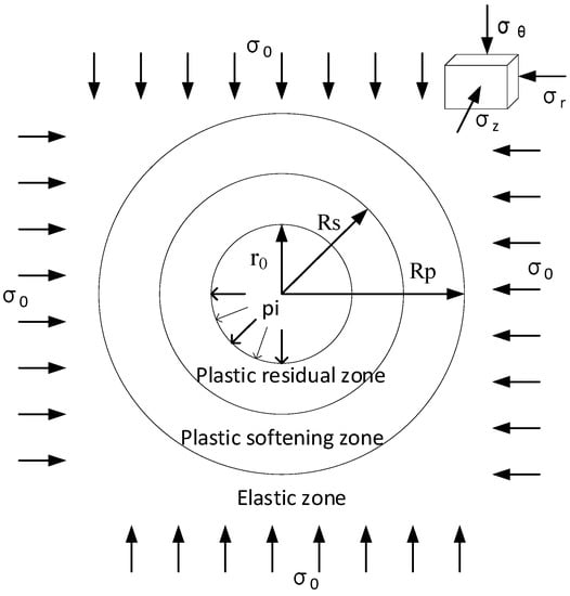
Figure 1.
Schematic diagram of the distribution of stress in a cylindrical tunnel.
2.2. D–P Criterion Yield Function
The D–P criterion is the conical yield surface tangent to the hexagonal pyramid of the M–C criterion proposed by Drucker and Prager and based on the generalized Mises criterion. Meanwhile, considering the effect of intermediate principal stress and the hydrostatic pressure stress field on the rock surrounding, the yield function is given as:
In Equation (1), and represent the first invariant of the stress tensor and the invariant of the stress tensor, respectively. and can then be written as:
In Equation (2), and are the strength parameters of surrounding rock defined by friction angle and cohesion , respectively.
In engineering practice, the ratio-specific value b is generally applied to express the relationship between the intermediate principal stress , the major principal stress , and the minor principal stress :
In Equation (5), 0 ≤ b ≤ 1 and increases with increasing intermediate principal stress. Equation (5) can then be combined with Equation (2):
where:
The D–P criterion expression can be modified by combining the above equations:
where:
3D stress analysis of a circular tunnel rock mass can be regarded as a plane strain problem in polar coordinates. The stress state of surrounding rock satisfies the following relationship:
In Equation (10), represent the circumferential stress, axial stress, and radial stress of the rock surrounding the tunnel, respectively.
2.3. Strain-Softening Model
The elastoplastic deformation of surrounding rock can be deduced in accordance with the theory of plastic mechanics by calculating the weakening behavior of the strength parameters [28]. If the D–P criterion satisfies the yield function in the strain-softening zone, the expression of the yield function has the following form:
In Equation (11), , whereas the most extensively accepted deviatoric plastic strain , regarded as the strain-softening parameter, can be determined by the difference between the circumferential plastic strain and radial plastic strain . The expression can be defined as [24]:
In Equation (12), and represent the major principal plastic strain and minor principal plastic strain of the surrounding rock, respectively.
In accordance with the theory of plastic mechanics, the widely used Mohr–Coulomb plastic potential function G could be written as:
A correlation exists between the plastic strain of surrounding rock and the plastic potential function G. Following the theory of plastic potential function, the following relationship can be deduced:
In Equation (14), is the dilatancy coefficient and is the angle of expansion of the rock mass, which varies with the surrounding pressure and type of rock mass.
The dilatancy behavior of rock surrounding a deep circular tunnel is affected by plastic shear deformation and confining pressure of the rock mass [9,10,13]. Detournay et al. [3] proposed that the dilatancy coefficient and the deviatoric plastic strain show an exponential decay relationship. Subsequently, Medhurst [29] analyzed the variation in the dilatancy coefficient with deviatoric plastic strain η under different confining pressures through triaxial experiments and obtained the following fitting formula:
where:
Through an analysis of previous studies and triaxial tests, Alejano [10] identified the relationship between the peak dilatancy angle , the confining pressures , and the peak internal friction angle by fitting the test data as:
In Equation (16), is uniaxial compressive strength and is the confining stress.
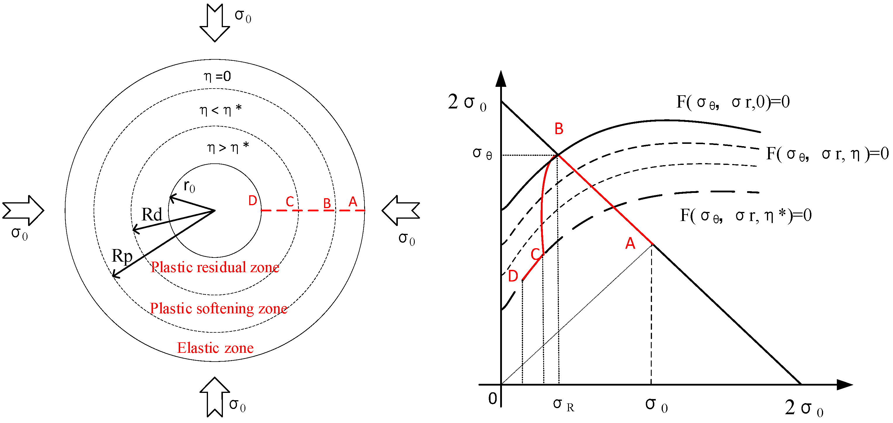
The results of previous studies [23,30,31] indicated that the tunnel excavation procedure results in a progressive decline in confining stress from to . In Figure 2, point A indicates that the rock mass falls within the initial hydrostatic pressure field. The radial stress of surrounding rock decreases progressively from point A to point B during the tunnel excavation process. The critical radial stress of surrounding rock at point B of the elastic–plastic boundary can be obtained by theoretical calculation. The surrounding rock enters the plastic yield stage beyond the elasto-plastic boundary point B and the surrounding rock parameters experience approximately linear attenuation with increasing strain-softening parameter . The distance between point C and point D demonstrates that the surrounding rock enters the residual stage. In other words, point C signifies that the surrounding rock transitions from the softening stage to residual stage.
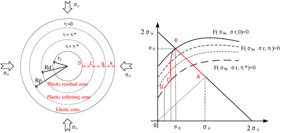
Figure 2.
Division of the deformation zone of the surrounding rock and variable path of stress during different stages according to Alonso et al. [23].
Therefore, the change in the strength parameter in the plastic softening zone, along with the softening parameter, satisfies the following formula [24,32,33]:
In Equation (17), is the transition point from the plastic softening zone to residual zone and the superscripts “p” and “r” denote the maximum peak and minimum remaining value of the strength parameters of surrounding rock, respectively.
3. Calculation of Stress and Displacement in the Elastic–Plastic Zone
3.1. Basic Equation
According to plane strain and the assumption of axisymmetry, the equilibrium equation of a circular tunnel can be simplified as:
For a small strain problem, the tangential strain and radial strain of the surrounding rock satisfy the geometric equation:
In Equation (20), represents the radial migration of the surrounding rock.
3.2. Calculation of Rock Mass Deformation in the Elastic Region
According to elastic–plastic mechanics, tangential stress , radial stress , and radial displacement can be expressed as:
In Equation (21), E is Young’s modulus and v is Poisson’s ratio.
Using Equations (9) and (21), the peak value of critical radial stress can be obtained as:
From Hooke’s law, the stress and strain components at the critical points of the elastic and plastic region are calculated as:
3.3. Calculation of Yield Deformation of the Rock Mass in the Plastic Zone
The strength parameters of the surrounding rock vary with the softening coefficient in the plastic region. For this reason, previous studies have provided widely divergent solutions for the softening behavior of rock mass. Brown [5] used the finite difference method to obtain the yield deformation of the soft rock mass surrounding a tunnel. Lee and Pietruszczak [24] subsequently improved Brown’s calculation method and proposed a numerical method with the increment of radial stress in the strain-softening zone represented as a series of concentric rings.
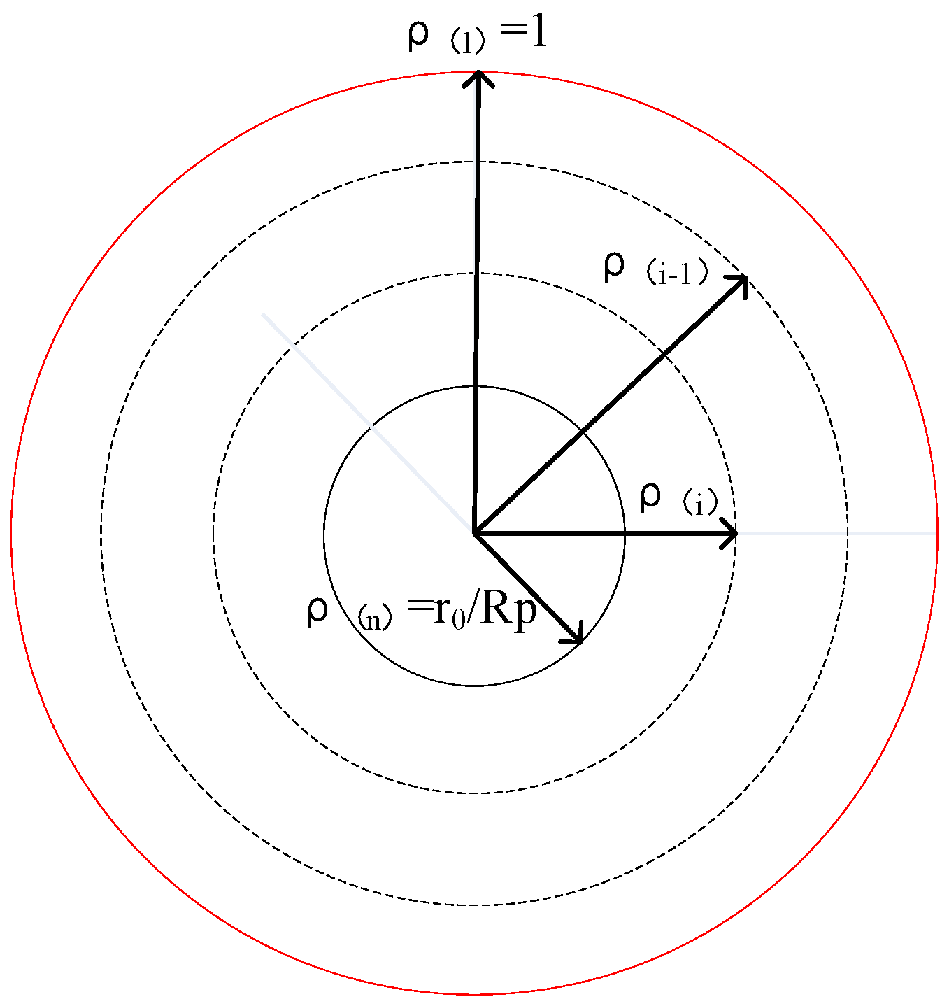
As shown in Figure 3, the present study adopted the method by Lee and Pietruszczak to uniformly divide the radial stress in the plastic zone into n concentric rings. The normalized radius of the inner and outer boundaries of the ith annulus are and . The increment in radial stress of each ring can be obtained as:
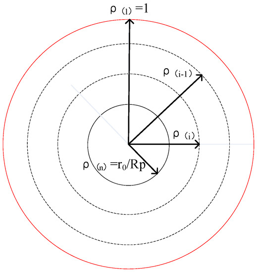
Figure 3.
Spatial distribution of the normalized radius division of the plastic zone.
Therefore, the radial stress of the ith radius can be expressed as:
Substituting Equation (26) into Equation (11), the following is obtained:
therefore:
The elastic strain of the rock mass in the plastic zone in terms of stress with consideration of the initial hydrostatic stress can be expressed as:
According to Hooke’s Law, the increase in elastic strain can be calculated as:
By substituting Equation (29) into the equilibrium equation [Equation (18)], the following is obtained:
The ith normalized radius is obtained as:
During the yield stage of the surrounding rock, total strain of each concentric ring can be decomposed into elastic strain and plastic strain components as:
By substituting Equation (32) into the Strain Coordination equation [Equation (19)], the following can be obtained:
or:
Setting:
By substituting Equation (34) into Equation (33), the following can be obtained:
By combining Equations (34) and (35), the following equation can be obtained:
where ; ; ; .
Therefore, the plastic softening parameter can be written as:
The total strain of the ith ring can be obtained as:
The above process is repeated n times when , . The plastic radius can be obtained by the calculation:
The radial displacement can then be calculated from the following relationship:
4. Verification of the Proposed Algorithm
The present study investigated the effectiveness of the proposed algorithm by comparing the results of the proposed algorithm with those of Lee [24] and Wang [32]. The proposed algorithm was applied to a circular tunnel with an excavation radius . The input data were , , , , , , , , , and .
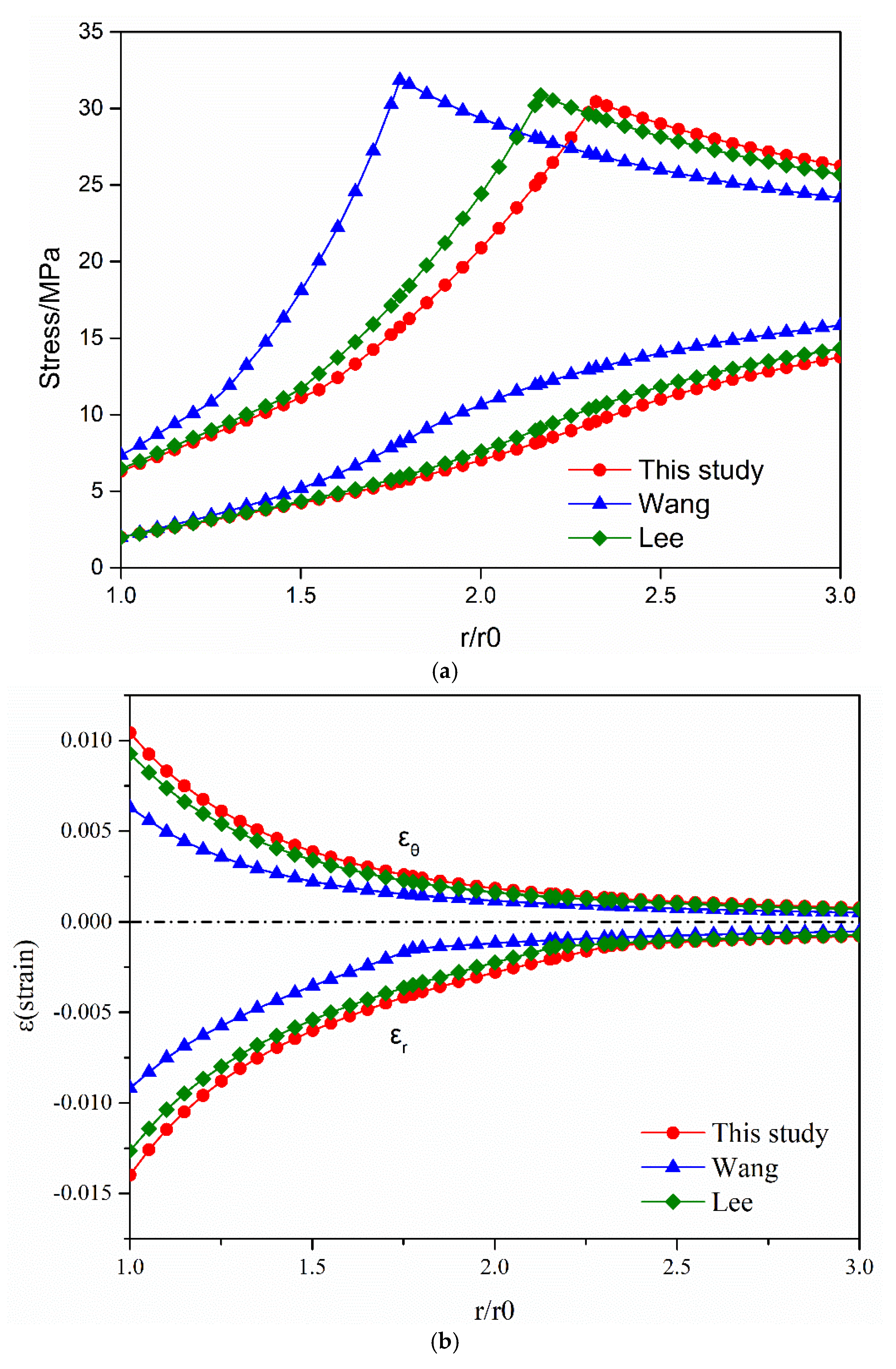
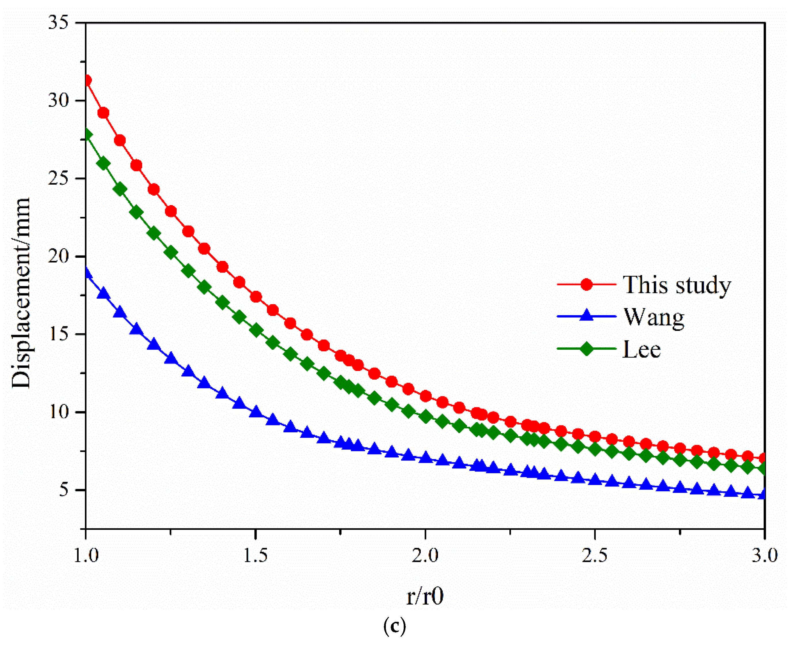
(1) Figure 4 shows the results of the three approaches, including the stress components, the strain components, and displacements.
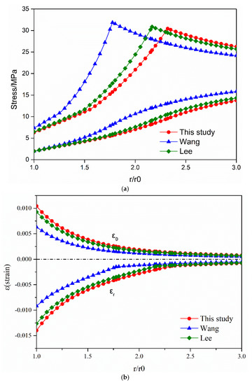
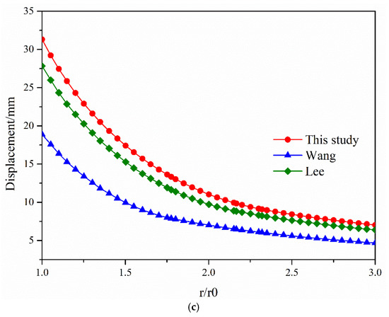
Figure 4.
Distributions of stress, strain, and radial displacement under different algorithms: (a) distribution of stress; (b) distribution of strain; (c) distribution of radial displacement.
As shown in Figure 4a, the tangential stress curve first gradually increased and then decreased with the increase of , and the tangential stress reached a maximum at the elasto-plastic boundary. Figure 4b,c show that the maximum strain and displacement occurred at the surface of the excavated tunnel. The three criteria could be ranked by strain and displacement as D–P criterion > M–C Coulomb criterion > unified strength criterion.
(2) An analysis of the distribution of stress, strain, and displacement curves showed that the results obtained by the D–P and M–C criteria were similar. The D–P criterion obtained the largest range of the plastic zone, followed by the M–C Coulomb criterion, with the unified strength criterion obtaining the smallest range. The stress, strain, and displacement calculated by the unified strength criterion were obviously more conservative than those by the D–P criterion. The analysis showed that the Unified Strength Theory may underestimate the plastic radius and the radial displacement, resulting in the calculated support strength underestimating the pressure experienced in a real-world tunnel engineering project.
5. Discussion
The present study set the intermediate principal stress coefficient b of the surrounding rock to 0, 0.25, 0.5, 0.75, and 1 to explore the influence of intermediate principal stress on the redistribution of stress, strain, plastic zone development, the ground response curve, and the shear dilatant.
5.1. The Effect of Intermediate Principal Stress on the Distribution of Stress and Strain of Surrounding Rock
The prediction of the range of variation of stress and strain is an important basis for studying the stability of surrounding rock after tunnel excavation.
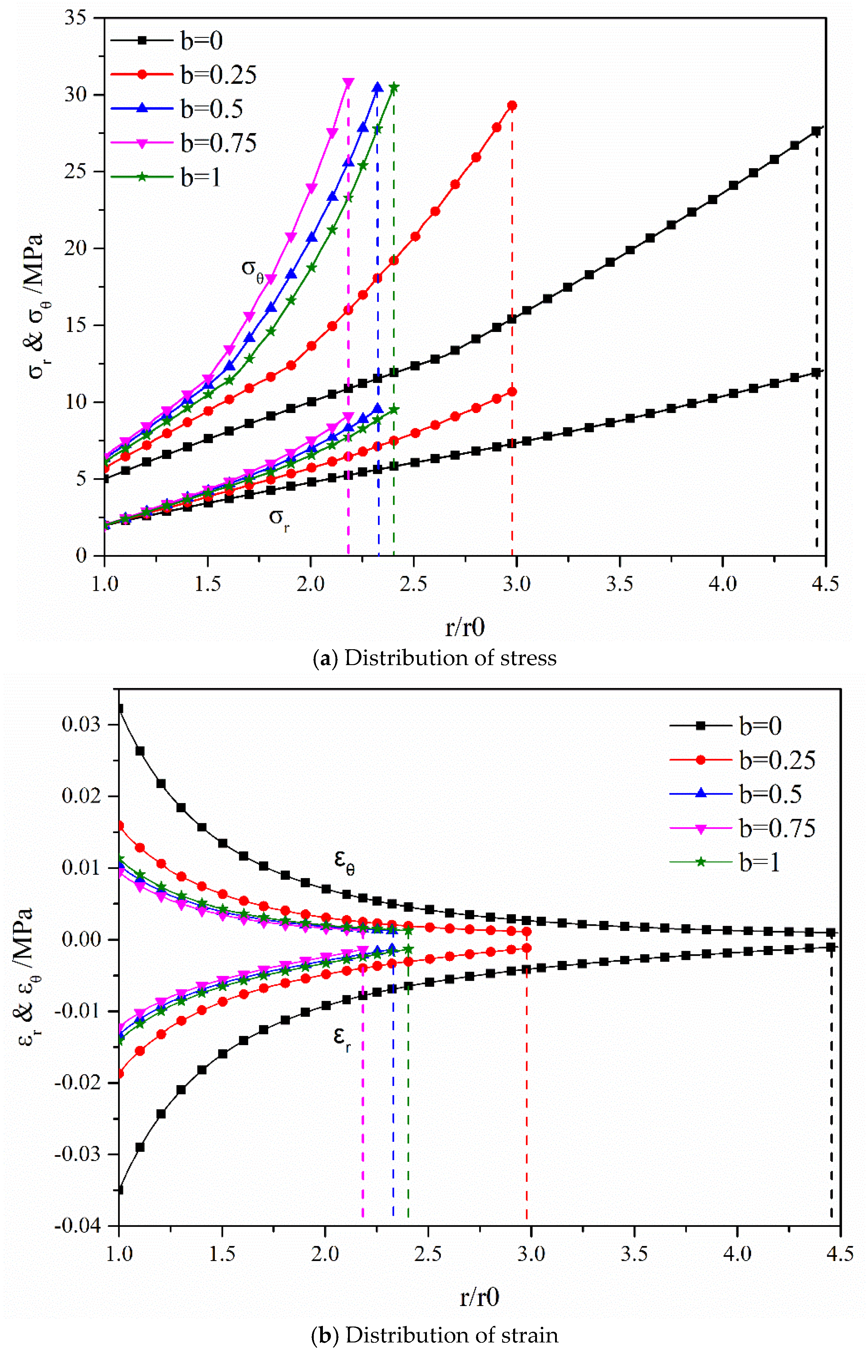
Figure 5 shows the variation in the stress and strain curves with r in the plastic zone for different intermediate principal stress coefficients b. The stress curves showed a rising tendency with increasing depth of surrounding rock under different b, whereas strain showed an opposite pattern.

Figure 5.
Effect of different intermediate principal stress on the distribution of stress and strain.
The position of the dotted line in the stress and strain curve gradually shifted to the left as b increased from 0 to 0.75 and the peak stress gradually increased. This observation indicated that the plastic radius of the surrounding rock decreased, whereas the rate of change of stress increased. As b increased from 0.75 to 1, the position of the dotted line in the stress and strain curve shifted to the right and the peak stress showed a slight decreasing trend. The plastic radius first decreased and then increased with increasing intermediate principal stress coefficient b from 0 to 1. Furthermore, the spacing between the dashed lines gradually decreased and then increased with increasing intermediate principal stress coefficient b from 0 to 1, indicating that intermediate principal stress inhibited the development of the plastic zone, although this effect showed an interval property.
Within increasing b from 0 to 0.75, the intermediate principal stress inhibited the plastic radius, although this inhibitory effect weakened with increasing intermediate principal stress. Intermediate principal stress promoted the development of the plastic region as b increased from 0.75 to 1. This result could be attributed to the increase in confining pressure improving the bearing capacity of the rock mass. However, damage of the rock occurred when the confining pressure exceeded a certain threshold (b = 0.75).
Intermediate principal stress generally showed a strong interval effect. Within a certain range, intermediate principal stress can effectively regulate the deformation of surrounding rock and restrain the expansion of the plastic zone.
5.2. The Effect of Intermediate Principal Stress on the Development of the Plastic Range
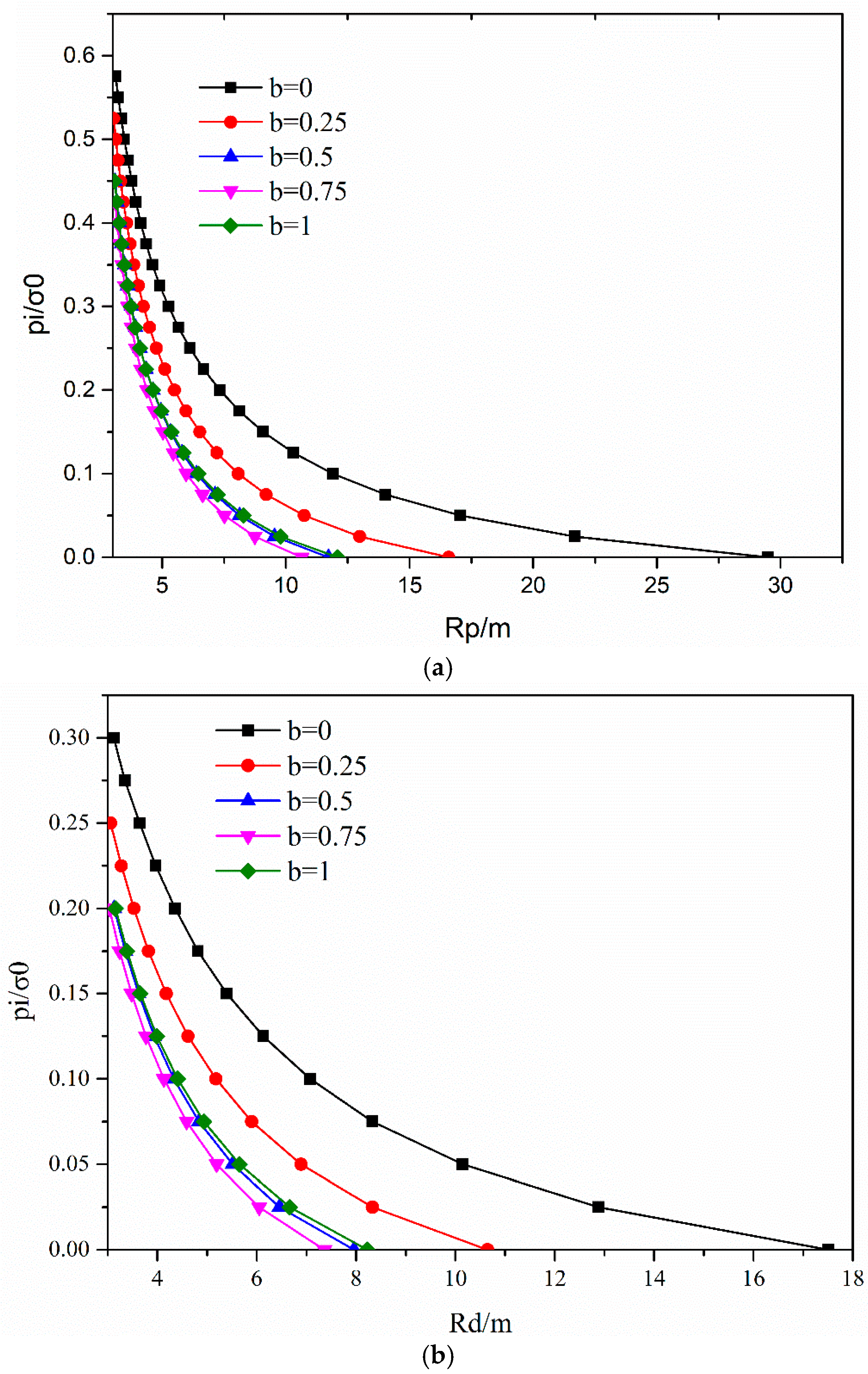
Figure 6 shows the distributions of the post-peak failure radius and residual radius to allow the study of the change in the plastic radius under different intermediate principal stress and support resistance.
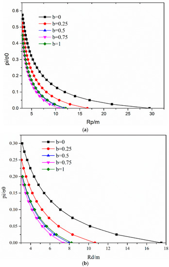
Figure 6.
The change in the plastic radius and residual radius under different intermediate principal stress: (a) plastic radius; (b) residual radius.
Figure 6 shows the relationships of and with pi. The results show distinct differences in the evolution of the plastic radius under different intermediate principal stress.
The density of points on the curve gradually decreased with the uniform decrease in support pressure. This result indicated increasing rates of change in the plastic radius and residual radius and that support pressure is inversely related to the strength of the restraining effect on the plastic radius of the surrounding rock. Figure 6b shows that the point of intersection between the curve and the Y-axis represented the critical support pressure of surrounding rock. In addition, with complete release of the support pressure, the plastic radii and residual radii both reached their maximum values (shown in Table 1). The plastic radius and the residual first decreased and then increased with changing intermediate principal stress coefficient b from 0 to 1, with the minimum appearing at b = 0.75. However, the proportion of residual radius in the plastic zone first increased, reaching a maximum at b = 0.75, and then decreased.

Table 1.
The plastic radii and residual radii when .
In conclusion, the rates of change in the plastic radius and residual radius gradually increased with decreasing support pressure. The intermediate principal stress showed an interval effect on the plastic radius and residual radius. However, this interval effect decreased with increasing supporting pressure. Therefore, the consideration of the influence of intermediate principal stress on the self-supporting capacity of rock mass is necessary when evaluating the disturbance of the stability of rock mass by excavation and the reliability of the adopted support structure design.
5.3. Influence of Support Pressure pi on Dilatancy Coefficient
During tunnel excavation engineering, excavation unloading is an important factor affecting the instability of a tunnel. Therefore, adopting a reasonable support structure is beneficial to improving the stability of surrounding rock. Figure 7 demonstrates relationships between supporting pressure and the dilatancy coefficient at the tunnel opening under different intermediate principal stress. Under a pi = 0, the same dilatancy coefficient was calculated under different intermediate principal stress coefficients b. The dilatancy coefficient increased non-linearly with increasing support pressure . The increase in support pressure inhibited the development of the plastic zone and increased the dilatancy coefficient of surrounding rock. The dilatancy effect of the surrounding rock tended to stabilize when the support pressure (elastic–plastic critical pressure). This is because under the constant supporting pressure, the plastic zone of the surrounding rock is restrained to a certain extent, thereby inhibiting plastic deformation.
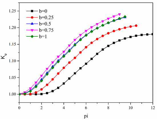
Figure 7.
Variation in the dilatancy coefficient at the tunnel opening with supporting pressure.
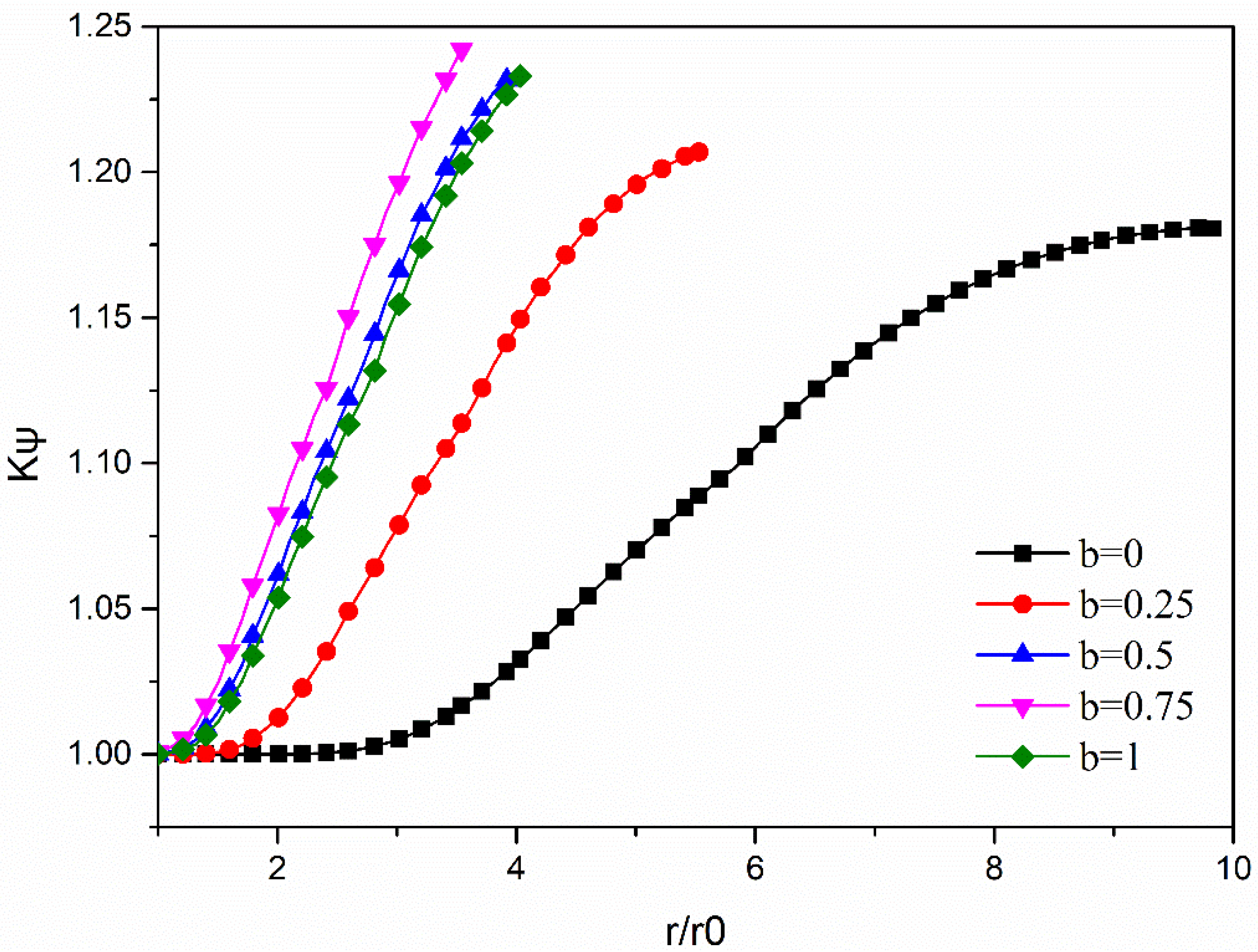
5.4. Influence of Intermediate Principal Stress on the Dilatancy of Surrounding Rock
As previously mentioned, the plastic radius decreased whereas the dilatancy coefficient increased with increasing support pressure . Figure 8 shows the changes in the dilatancy coefficient with changing surrounding rock depth r in the plastic region.
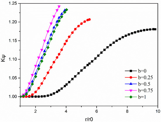
Figure 8.
Relationship between the dilatancy coefficient and intermediate principal stress.
The point of intersection between the curve and the Y-axis represented the value of , indicating that plastic deformation of the rock mass was fully developed at the boundary of the tunnel opening. As shown in Figure 8, the dilatancy coefficient gradually decreased from the elastic–plastic boundary to the tunnel opening wall under different intermediate principal stress. The peak dilatancy occurred in the elastic region and elasto-plastic critical region, along with the peaks in the strength parameters of surrounding rock. In addition, the dilatancy confident under the intermediate principal stress coefficient b (0.5, 0.75, and 1) tended to be close in the plastic region. In contrast, the distribution of the dilatancy coefficient in the plastic zone revealed obvious differences among three conditions (b = 0, 0.25 and 0.5), especially under the conditions of principal stress coefficient b = 0. Table 2 shows the influences of intermediate principal stress b on the dilatancy coefficient . The dilatancy coefficient initially increased and then decreased in the strain-softening zone with increasing intermediate principal stress coefficient b. In particular, the plastic zone of surrounding rock calculated under different intermediate principal stress showed considerable differences, which resulted in the clearly different curve trajectories of the dilatancy coefficient. However, the differences in were due to the increase and decrease in the intermediate principal stress coefficient b and plastic radius , respectively, which resulted in an increase in the slope of the dilatancy coefficient . As indicated in Equation (15) to Equation (16), there was exponential variation in with .
Table 2.
Peak dilatancy coefficient under different parameter b stresses for .
In summary, the dilatancy coefficient curves showed differences in the plastic region when the intermediate principal stress coefficient b < 0.5 and the dilatancy coefficient curve presents a similar trend for 0.5.
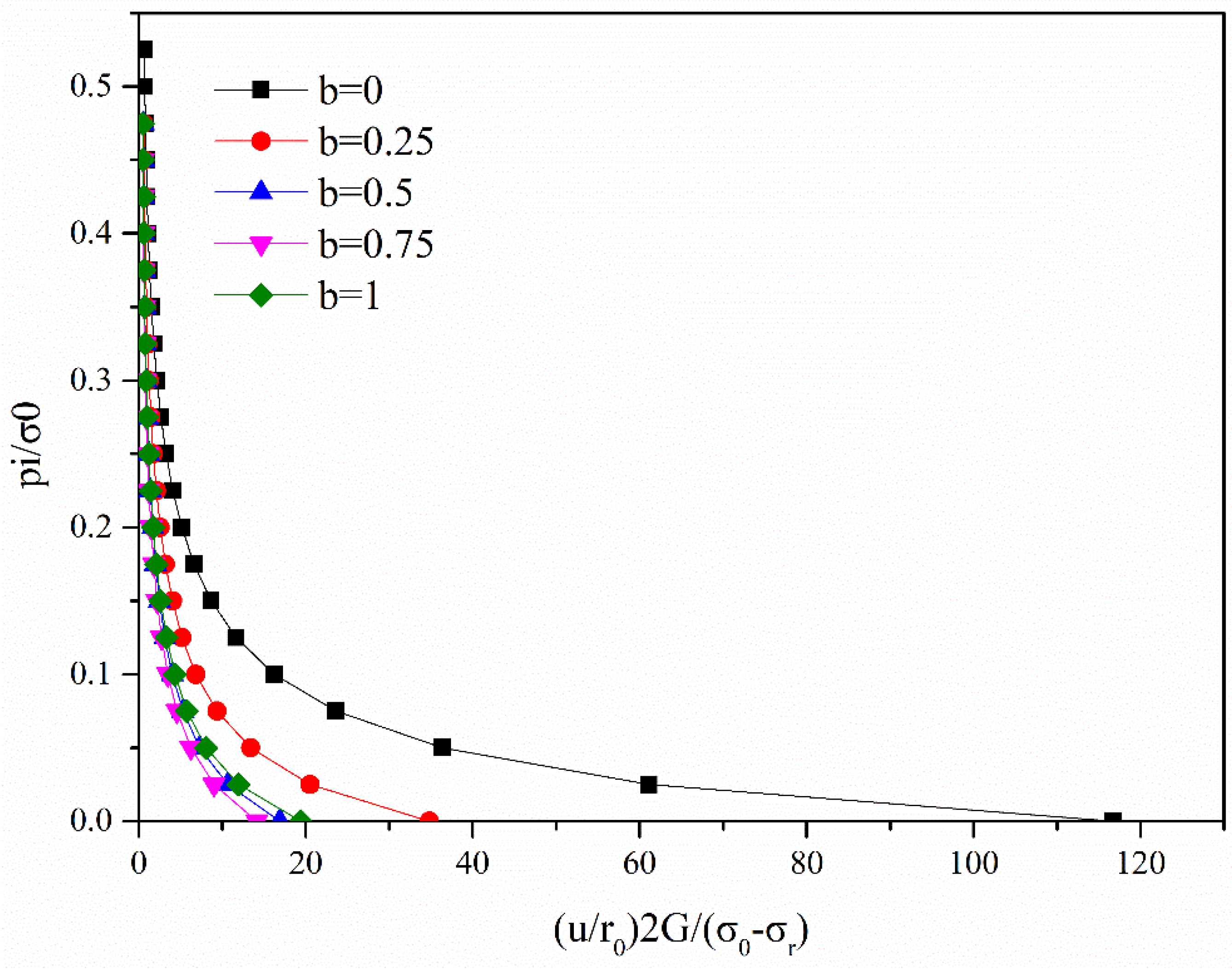
5.5. The Effect of Intermediate Principal Stress on the Ground Response Curve (GRC)
The present study applied the ground response curve (GRC) to reflect the relationship between radial displacement around the cavern and tunnel support pressure, thereby allowing analysis of the stability of surrounding rock. Figure 9 shows the ground response curves under different intermediate principal stress. The radial displacement, which is inversely proportional to the supporting pressure, gradually decreased with increasing supporting pressure. Furthermore, there were evident effects of intermediate principal stress on the GRC, particularly under b = 0, as shown in Figure 9. As the intermediate principal stress coefficient b increased from 0 to 0.75, the dimensionless at the tunnel opening gradually decreased by 63.43%, 51.52%, and 16.30%, respectively. Nevertheless, with an increase in b from 0.75 to 1, the dimensionless increased by 37.33%. In addition, the maximum radial displacement occurred for b = 0 when pi = 0, which could be attributed to a minimum restraining effect of the intermediate principal stress on the displacement in the plastic zone.
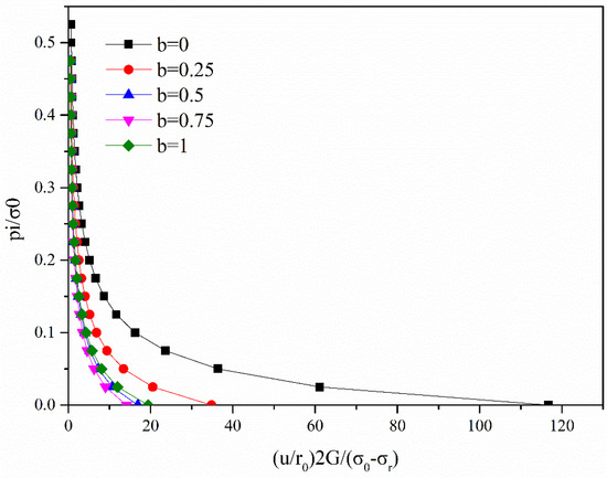
Figure 9.
The ground response curve (GRC) under different intermediate principal stress.
In summary, suppression of tunnel deformation by intermediate principal stress showed an interval effect and gradually decreased with increasing b. After b exceeded a certain threshold, it promoted deformation of the surrounding rock. Similarly, the restraining effect of supporting pressure pi on tunnel deformation gradually weakened with increasing pi.
6. Conclusions
Considering that confining pressure can improve the bearing capacity of surrounding rock, the present study proposed a numerical solution for determining the distribution of stress and displacement of a circular tunnel under uniform pressure. This solution was based on the strain-softening model and the uncorrelated flow rule following on the D–P criterion. The proposed algorithm was verified by comparing the obtained results with those of the yield criteria by Lee (M–C) and Wang (Unified Strength Theory). The current study also discussed the effect of intermediate principal stress on mechanical properties of surrounding rock. The main conclusions of the present study are summarized below.
The results of the algorithm proposed in the present study indicated that the unified strength yield criterion is too conservative and that the results under the D–P criterion are similar to that under the M–C criterion.
The plastic radius , the residual , and the deformation of surrounding rock first decreased and then increased as the intermediate principal stress coefficient b changed from 0 to 1, with the minimum appearing at b = 0.75. This result indicated that intermediate principal stress generally showed a strong interval effect.
The dilatancy coefficient increased nonlinearly from the tunnel opening wall to the elastic–plastic boundary (b < 0.25), while the dilatancy coefficient increases approximately linearly (b > 0.25).
Under a rigorous consideration of the influence of rock confining pressure, the reasonable estimation of the self-bearing capacity of surrounding rock is beneficial. A consideration of the interaction between surrounding rock bearing capacity and supporting pressure provides an important theoretical basis for the design and analysis of the stability of a circular tunnel excavation.
Author Contributions
C.S. conceived the research. J.L. deduced the calculation procedure. X.H. and J.L. wrote the original manuscript. X.Z. participated in the data analysis and manuscript modification. All authors have read and agreed to the published version of the manuscript.
Funding
This work was supported by National Natural Science Foundation of China (No. 41830110).
Institutional Review Board Statement
Not applicable.
Informed Consent Statement
Not applicable.
Data Availability Statement
Not applicable.
Conflicts of Interest
The authors declare that there are no conflict of interest regarding the publication of this paper.
References
- Li, S.C.; Hu, C.; Li, L.P.; Song, S.G.; Zhou, Y.; Shi, S.S. Bidirectional construction process mechanics for tunnels in dipping layered formation. Tunn. Undergr. Space Technol. 2013, 36, 57–65. [Google Scholar] [CrossRef]
- Huang, H.W.; Gong, W.P.; Khoshnevisan, S.; Juang, C.H.; Zhang, D.M.; Wang, L. Simplified procedure for finite element analysis of the longitudinal performance of shield tunnels considering spatial soil variability in longitudinal direction. Comput. Geotech. 2015, 64, 132–145. [Google Scholar] [CrossRef]
- Detournay, E. Elastoplastic model of a deep tunnel for a rock with variable dilatancy. Rock Mech. Rock Eng. 1986, 19, 99–108. [Google Scholar] [CrossRef]
- Ogawa, T.; Lo, K.Y. Effects of dilatancy and yield criteria on displacements around tunnels. Can. Geotech. J. 1987, 24, 100–113. [Google Scholar] [CrossRef]
- Brown, E.T.; Bray, J.W.; Ladanyi, B.; Hoek, E. Ground Response Curves for Rock Tunnels. J. Geotech. Eng. 1983, 109, 15–39. [Google Scholar] [CrossRef]
- Fama, M. Numerical Modeling of Yield Zones in Weak Rock. Anal. Des. Methods 1993, 49–75. [Google Scholar] [CrossRef]
- Carranza-Torres, C.; Fairhurst, C.T. Application of the Convergence-Confinement method of tunnel design to rock masses that satisfy the Hoek-Brown failure criterion. Tunn. Undergr. Space Technol. 2000, 15, 187–213. [Google Scholar] [CrossRef]
- Ghorbani, A.; Hasanzadehshooiili, H. A comprehensive solution for the calculation of ground reaction curve in the crown and sidewalls of circular tunnels in the elastic-plastic-EDZ rock mass considering strain softening. Tunn. Undergr. Space Technol. 2019, 84, 413–431. [Google Scholar] [CrossRef]
- Alejano, L.R.; Alonso, E.; Rodríguez-Dono, A.; Fernández-Manín, G. Application of the convergence-confinement method to tunnels in rock masses exhibiting Hoek–Brown strain-softening behaviour. Int. J. Rock Mech. Min. 2010, 47, 150–160. [Google Scholar] [CrossRef]
- Alejano, L.R.; Rodriguez-Dono, A.; Alonso, E.; Manin, G.F. Ground reaction curves for tunnels excavated in different quality rock masses showing several types of post-failure behaviour. Tunn. Undergr. Space Technol. Inc. Trenchless Technol. Res. 2009, 24, 689–705. [Google Scholar] [CrossRef]
- Song, F.; Rodriguez-Dono, A.; Olivella, S. Hydro-mechanical modelling and analysis of multi-stage tunnel excavations using a smoothed excavation method. Comput. Geotech. 2021, 135, 104150. [Google Scholar] [CrossRef]
- Azadi, M.; Hosseini, S. Analyses of the effect of seismic behavior of shallow tunnels in liquefiable grounds. Tunn. Undergr. Space Technol. 2010, 25, 543–552. [Google Scholar] [CrossRef]
- Alejano, L.R.; Alonso, E. Considerations of the dilatancy angle in rocks and rock masses. Int. J. Rock Mech. Min. 2005, 42, 481–507. [Google Scholar] [CrossRef]
- Yao, Y.; Hu, J.; Zhou, A.; Luo, T.; Wang, N. Unified strength criterion for soils, gravels, rocks, and concretes. Acta Geotech. 2015, 10, 749–759. [Google Scholar] [CrossRef]
- Singh, A.; Rao, K.S.; Ayothiraman, R. An analytical solution to wellbore stability using Mogi-Coulomb failure criterion. J. Rock Mech. Geotech. Eng. 2019, 11, 1211–1230. [Google Scholar] [CrossRef]
- Al-Ajmi, A.M.; Zimmerman, R.W. Relation between the Mogi and the Coulomb failure criteria. Int. J. Rock Mech. Min. Sci. 2005, 42, 431–439. [Google Scholar] [CrossRef]
- Yu, M.H.; He, L.N. A New Model and Theory on Yield and Failure of Materials under the Complex Stress State. In Mechanical Behaviour of Materials-VI, Proceedings of the Sixth International Conference, Kyoto, Japan, 29 July–2 August 1991; Elsevier: Amsterdam, The Netherlands, 1992; Volume 1–4, pp. C841–C846. [Google Scholar]
- Xu, S.Q.; Yu, M.H. The effect of the intermediate principal stress on the ground response of circular openings in rock mass. Rock Mech. Rock Eng. 2006, 39, 169–181. [Google Scholar] [CrossRef]
- Hou, G.Y.; Niu, X.S. Perfect elastoplastic solution of axisymmetric circular openings in rock mass based on Levy-Mises constitutive relation and D-P yield criterion. Rock Soil Mech. 2009, 30, 1555–1562. [Google Scholar]
- Zhang, Q.; Wang, H.Y.; Wang, S.L.; Ge, X.R.; Shao, G. Deterioration elasto-plastic analysis of cracked surrounding rocks based on unified strength theory. Mtan Xuebao/J. China Coal Soc. 2010, 35, 381–386. [Google Scholar]
- Wang, F.; Qian, D. Elasto-analysis for a deep tunnel considering intermediate stress and strain-softening behavior. J. China Coal Soc. 2018, 43, 3329–3337. [Google Scholar]
- Singh, A.; Rao, K.S.; Ayothiraman, R. Effect of Intermediate Principal Stress on Cylindrical Tunnel in an Elasto-plastic Rock Mass. Procedia Eng. 2017, 173, 1056–1063. [Google Scholar] [CrossRef]
- Alonso, E.; Alejano, L.R.; Varas, F.; Fdez-Manin, G.; Carranza-Torres, C. Ground response curves for rock masses exhibiting strain-softening behaviour. Int. J. Numer. Anal. Methods Geomech. 2003, 27, 1153–1185. [Google Scholar] [CrossRef]
- Lee, Y.K.; Pietruszczak, S. A new numerical procedure for elasto-plastic analysis of a circular opening excavated in a strain-softening rock mass. Tunn. Undergr. Space Technol. 2008, 23, 588–599. [Google Scholar] [CrossRef]
- Cui, L.; Zheng, J.J.; Zhang, R.J.; Dong, Y.K. Elasto-plastic analysis of a circular opening in rock mass with confining stress-dependent strain-softening behaviour. Tunn. Undergr. Space Technol. 2015, 50, 94–108. [Google Scholar] [CrossRef]
- Zhao, X.G.; Cai, M. A mobilized dilation angle model for rocks. Int. J. Rock Mech. Min. 2010, 47, 368–384. [Google Scholar] [CrossRef]
- Khoiri, M.; Ou, C.Y. Evaluation of deformation parameter for deep excavation in sand through case histories. Comput. Geotech. 2013, 47, 57–67. [Google Scholar] [CrossRef]
- Kaliszky, S.; Lógó, J.; Havady, T. Optimal design of elasto-plastic structures under various loading conditions and displacement constraints. Arch. Immunol. Et Ther. Exp. 1989, 20, 169–173. [Google Scholar]
- Medhurst, T.P. Estimation of the In Situ Strength and Deformability of Coal for Engineering Design. Ph.D. Thesis, The University of Queensland, Brisbane, Australia, 1997. [Google Scholar]
- Zhang, Q.; Wang, H.-Y.; Jiang, Y.-J.; Lu, M.-M.; Jiang, B.-S. A numerical large strain solution for circular tunnels excavated in strain-softening rock masses. Comput. Geotech. 2019, 114, 103142. [Google Scholar] [CrossRef]
- Zhang, Q.; Li, C.; Guo, Q.; Min, M.; Wang, Y.; Jiang, B. A simple approach to the elasto-plastic coupling analyses of circular tunnels in confining pressure-dependent strain-softening rock masses. Geosystem Eng. 2017, 20, 261–270. [Google Scholar] [CrossRef]
- Wang, F.; Qian, D. Difference solution for a circular tunnel excavated in strain-softening rock mass considering decayed confinement. Tunn. Undergr. Space Technol. 2018, 82, 66–81. [Google Scholar] [CrossRef]
- Wang, S.L.; Yin, X.T.; Tang, H.; Ge, X.R. A new approach for analyzing circular tunnel in strain-softening rock masses. Int. J. Rock Mech. Min. 2010, 47, 170–178. [Google Scholar] [CrossRef]

Publisher’s Note: MDPI stays neutral with regard to jurisdictional claims in published maps and institutional affiliations. |
© 2021 by the authors. Licensee MDPI, Basel, Switzerland. This article is an open access article distributed under the terms and conditions of the Creative Commons Attribution (CC BY) license (https://creativecommons.org/licenses/by/4.0/).