Article

Thermal Performance Evaluation of a Tubular Heat Exchanger Fitted with Combined Basket–Twisted Tape Inserts

by
Hayder Q. A. Khafaji
1,
Hasanain A. Abdul Wahhab
2,
Sajda S. Alsaedi
2,
Wisam Abed Kattea Al-Maliki
2,3,
Falah Alobaid
3,* and
Bernd Epple
3
1
Department of Electromechanical Engineering, University of Technology-Iraq, Baghdad 19006, Iraq
2
Mechanical Engineering Department, University of Technology-Iraq, Baghdad 19006, Iraq
3
TU Darmstadt, Institut Energiesysteme und Energietechnik, Otto-Berndt-Straße 2, 64287 Darmstadt, Germany
*
Author to whom correspondence should be addressed.
Appl. Sci. 2022, 12(10), 4807; https://doi.org/10.3390/app12104807
Submission received: 29 March 2022 / Revised: 1 May 2022 / Accepted: 5 May 2022 / Published: 10 May 2022

Abstract

:
Features of the tubular type of heat exchanger were examined experimentally in the current study. A rig is fitted with a novel insert as a negative heat transfer increase technique. The core fluid used is air under steady heat flux and a turbulent discharge state (6000 ≤ Re ≤ 19,500) conditions. Two heat transfer augmentation inserts are employed; one is the basket turbulators utilized as a turbulator and placed inside the heat exchanger with a constant pitch ratio (PR = 150 mm), and the other is the basket turbulators together with twisted tape that are installed at the core of the basket turbulators. The measurements illustrated that the Nusselt number (Nu) was found to be higher by about 131.8%, 169.5%, 187.7%, and 206.5% in comparison with the plain heat exchanger for basket turbulators and the combined basket–twisted tape inserts with y/w = 6, 3, and 2, respectively. The highest thermal efficiency factor of the increased tubular heat exchanger is 1.63 times more elevated than that of the simple heat exchanger on average, due to a binary basket-quirky strip for a twisting percentage y/w equal to 2 under steady pumping energy. Further, practical correlations for the Nusselt number, as well as friction characteristics, were established and presented.

1. Introduction

Owing to the growing energy costs and manufacturing materials, researchers have given significant attention to building up efficient, compact, and economical thermal systems for different engineering applications such as nuclear reactors, chemical processing industries, solar heaters, etc. A highly efficient thermal system comes with augmented heat transfer using passive, active, or a combination of multiple passive or active techniques. The primary goals of these strategies are to increase the thermal efficiency of the existing systems whilst also actually reducing their size, weight, and operating costs. Consequently, the suitable design of these approaches constitutes a difficult problem in order to achieve heat transfer optimisation at reasonable increase in frictional forces. Using a passive strategy based on introducing turbulators in the flow route as augmentations, such as helical inserts [1,2], it was found that with increasing pitch, vortex shedding frequencies also rise, and that the highest amplitude of the vortex generated by conical-ring turbulators occurred at low pitches. It is discovered that the Nu number grows with rising Re number, and the optimum heat transfer is reached for the arrangement with the smallest pitch, for corrugated and grooved geometries [3,4,5]. As the pitch length is increased, the frequency of vortex shedding is also observed to rise, and the peak amplitude of vortex generated by conical-ring turbulators occurs at small pitches. Findings were made to show increasing Nu with rising Re, and maximum heat transfer is achieved at the minimum pitch configuration for ribbed and grooved geometries [3,4,5]. The dimensions of the grooves, the rotational speed, and the axial velocity of the fluid show a significant impact on their heat transfer. The results of vortex generators [6,7] show that increases in distance between two vortex generators increase the mean Nusselt number, and other types of turbulators [8,9,10] are commonly used to improve heat transfer inside thermal systems due to the simple manufacturing process, easily employed compared to the active technique. Employing conical-ring turbulators at three-pitch ratios (PR) 2, 3, and 4, Ibrahim et al. [11] demonstrated augmentations of 330, 419, and 765 percent, respectively. They also discovered that using the diverging conical-ring with a smaller setup can increase the enhancement effectiveness by 1.291 (PR). Xu et al. [12] examined the effect of winglet vortex generators on a horizontal circular tube in a forced convection setting with a Re number range of 6000–34,000. They concluded that winglet tensor flow with a pitch ratio of 1.6, a barrier ratio of 0.3, and an attack angle of 45° boosted the heat transfer rate by up to 4.88 times under constant heat flux conditions. The perforated inserts are usually used to generate strong turbulence/vortex flows, which helps further improvement of turbulence intensity with reasonable increment in pressure loss. Chamoli et al. [13] performed an investigation of the perforated vortex generators’ influences on forced convection in a circular tube. They observed that the perforated insert improves the thermal performance by 1.65 times under constant pumping power conditions. In comparison with the conventional conical-ring, Nakhchi et al. [14] claimed that the recirculation flow by holes of perforated conical-rings with varying geometrical characteristics can improve the heat transfer rate by about 35.48% and decrease the pressure loss by about 88.06%. Attempts to enhance thermal efficiency took place by utilising the advantages of twisted-tape swirl generator inserts as cross hollow twisted-tape [15]. A plain tube’s experimental data are compared to the standard validation. With the increase in the hollow width from 6 mm to 10 mm, the Nu number and friction factor (f) subsequently increase. Compared to the flat tube, Nu and f increase by 93 percent–120 percent and 883 percent–1042 percent, respectively, for the 6 mm hollow width rise. Perforated double and triple counter twisted-tape [16,17] evaluated the impacts of perforated double and triple-counter twisted-tapes on heat transmission and fluid friction properties in a heat exchanger tube. Except for 1.2 percent porosity, the measurements showed that the Nu, f, and thermal enhancement efficiency improved with porosity reduction. The findings also demonstrated better heat transfer of the tape-fitted tube, accompanied by a consequent rise in the f. The thermohydraulic features inside the heat exchanger tube inserted with multiple-twisted-tapes [18]. The measurements revealed a signed rise in heat transfer and f in comparison with single-twisted tape, compound-twisted tape, and twisted tube [19]. An effort to examine the thermo-fluidic transportation capability of a laminar flow passing through tubular-heat exchangers utilizing a composite design consisting of the combination of twisted-tapes and twisted-tubes. The results show that raising the twist-pitch and Re improves the total efficiency with twisted-tape with rectangular-cut [20]. Nu numbers in a tube with a rectangular-cut twisted-tape insert increased 2.3–2.9 times while f increased 1.4–1.8 times to a smooth tube with perforated helical twisted-tapes [21]. The testing findings show that using perforated helical twisted-tapes reduces friction loss when compared to helically twisted-tape and helical screw-tape [22]. Heat transfer properties and f were tested on helical screw elements with variable twisted ratios and helical screw inserts with various pitch lengths. The research reveals that the total Nu and f reduce as the spacer length or twisted ratio increases for flat tube, spiral ribs, and twisted-tapes [23]. The findings of V-Shape twisted jaw [24] reveal in excess of unity thermal power factor readings with an increasing trend as the number of turbulators increases, demonstrating the practicality of employing these turbulators realistically. For the tube with punched delta-winglet vortex generators [25], a better temperature distribution is obtained, resulting in a better temperature gradient than that obtained with the smooth tube. It was also discovered that, as the attack angle increases, the temperature distribution also follows a trend towards a relatively homogenous temperature profile, and tape inserts combined with cables nails [26]. Prior research indicated that the twisted-tape swirl generator has excellent heat transfer performance by producing strong swirling flow and that the perforated twisted-tape was helpful in lowering pressure loss. However, according Promvonge et al. [27], a composite heat transfer enhancement achieved by combining various heat transfer augmentation approaches may be used to provide an augmentation that improves the thermal performance of either of the procedures functioning independently. They discovered that using a conical-ring and twisted-tape with a twisted ratio TR = 3.75 increases the enhancement efficiency by 1.96 times. Eiamsa et al. [28] offered another experimental research to clarify the impact of the combination insert of regularly/constant wire coil pitch ratio and the twisted-tape on thermal performance behaviours. According to the findings, combining inserts with decreasing coil pitch ratios can boost enhancement efficiency by up to 1.25 times.
Kurnia et al. [29,30] summarized the contribution of entropy production due to both heat transfer and viscous dissipation, in addition to the Bejan number over different twisted band designs, and found that helical tubes having twisted-tape inserts exhibit poorer heat entropy production compared to tubes without. This suggests that for heat transfer equipment, a helical tube with a twisted-tape insert appears to be more effective. The augmentation of heat transmission by various types of inserts, as described in the preceding literature, is largely reliant on the designs and geometries of the inserts. In light of this, it is created a novel design of inserts (basket turbulators) to improve a tubular heat exchanger. When compared to a heat exchanger without inserts, basket turbulators with a spacing ratio of 4.2 can increase heat transfer rate by 115.9 percent, according to their research. The analysis of the work [31] indicates promising findings on the problem of heat transfer augmentation and inspires the current effort to extend the research using basket turbulators in conjunction with twisted-tapes swirl generators placed inside a circular tube under the same operating circumstances. The compound augmentation is supposed to provide a high heat transfer rate by introducing swirl flow and significant fluctuation. As a result, the thermal performance, heat transfer, and friction losses of a tubular heat exchanger coupled with compound augmentation, i.e., basket turbulators with twisted-tapes swirl generator with three twist ratios (y/w = 2, 3, and 6) are investigated experimentally in the current work. There is no evidence of such coupled augmentations in the literature. The experiments were divided into three parts: a study of the thermal performance, heat transfer rate, and friction losses of the basket turbulators in a turbulent flow regime (6000 ≤ Re ≤ 19,500) under constant heat flux, the introduction of a novel compound augmentation, and the development of empirical correlations to predict the rate of heat transfer and friction losses. Therefore, the novelty of the current paper is carrying out an experimental study on novel inserts using basket turbulators with twisted-tapes swirl generators.

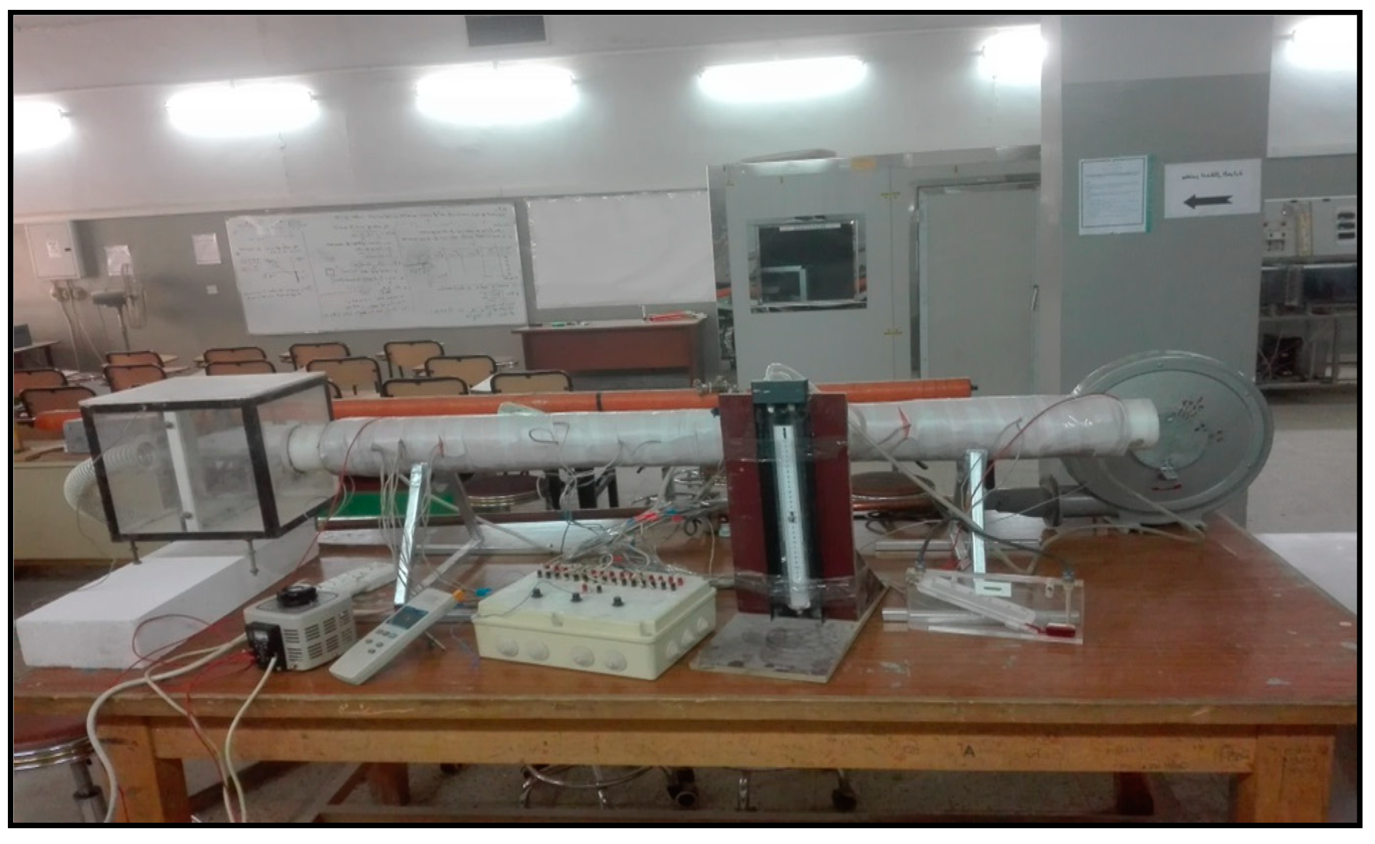
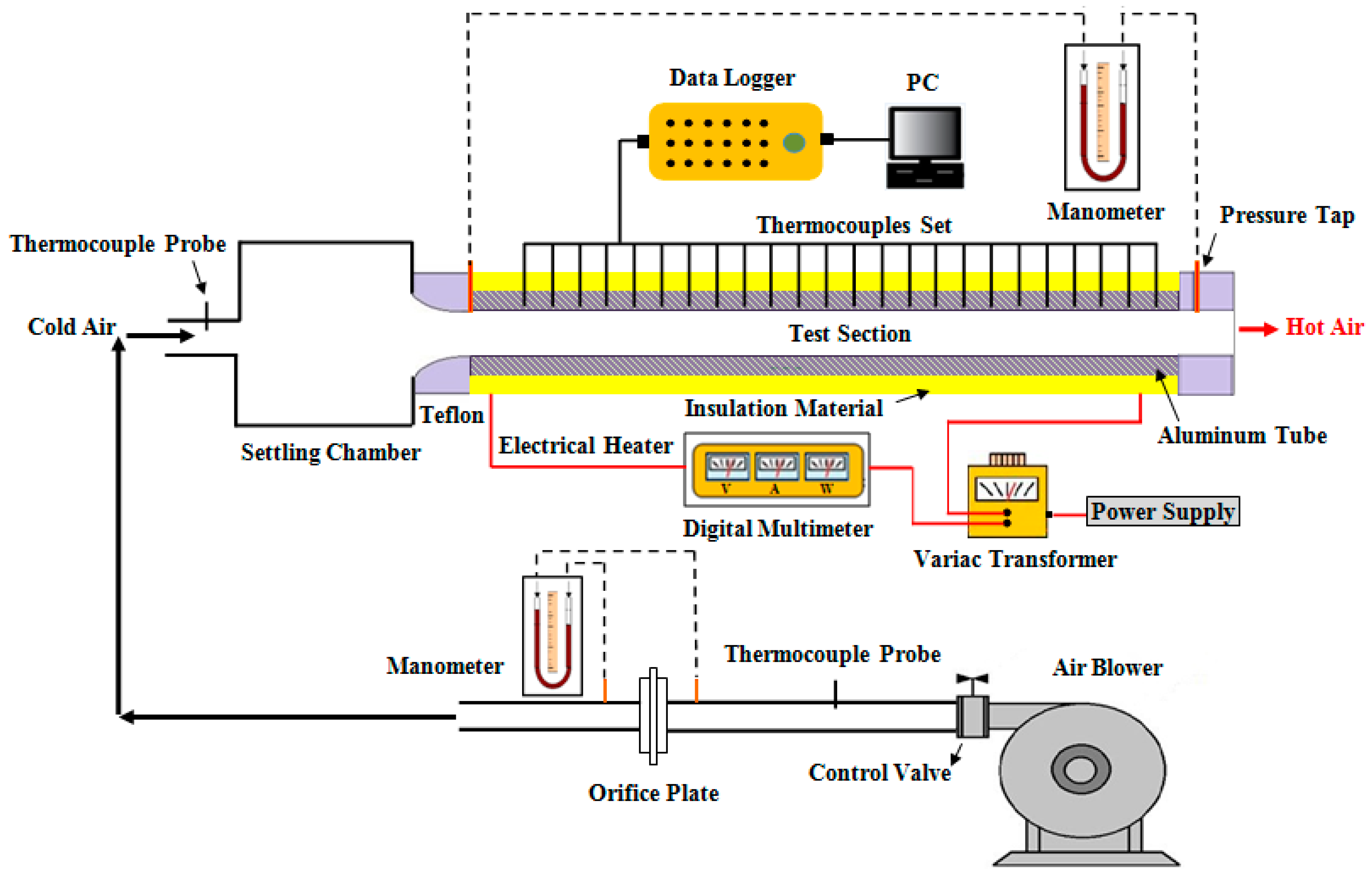
2. Experimental Apparatus Description

To perform the experiments, an open-loop experimental apparatus located in a normal environment (1 atm) is used. The experimental apparatus is shown by the photographic view and schematic diagram in Figure 1 and Figure 2. The experimental setup mainly consists of a tubular heat exchanger, augmentation inserts, a data collection method, and measurement devices. The heat exchanger is built of an aluminium conduit with an outside diameter of 5 cm, an inner diameter of 4.5 cm, a thick of 0.25 cm, and a length of 13.50 cm. Figure 3 shows the geometric configurations of the tubular heat exchanger, basket turbulators, and twisted-tapes inserts. The twisted-tapes are made of galvanized iron and have twist ratios of TR = 2, 3, and 6 (w = 1.5 cm, y = 3–9 cm). Five pieces of basket turbulators, which are made from the iron bar, are used in this experiment with a constant distance between them (PR = 150 mm). The basket turbulators are inserted into the heat exchanger in a wall-attached position, and the twisted tapes are tightly fitted into the centre of the basket turbulators. The heat exchanger is Ohmically heated using continuously whining flexible nickel–chrome wire to obtain a boundary condition with a homogeneous heat flux. A voltage regulator is applied to regulate the input power and automatically maintain the heat flux within acceptable limits along with the heat exchanger. Twenty-two calibrated thermocouples (type k) with a temperature range from −58 to 1298 °C are used in positions which are eighteen thermocouples installed along the heat exchanger’s wall to determine the distribution of the wall temperature. To acquire the bulk air temperature, four thermocouples are fitted in the input and exit sections. Table 1 shows the placement of the thermocouple along the heat exchanger. All thermocouples are linked to a selection switch, which is subsequently linked to a multi-channel digital data logger system. The exterior surface of the heat exchanger was thermally insulated by an asbestos layer and a fibreglass sheet to reduce heat loss.

3. Governing Equations

In this experiment, air supplied by an electrical blower serves as the working fluid and is circulated through the heat exchanger. In a steady-state instance, the net heat energy transmitted from the electrical heater to the air through the heat exchanger wall was calculated as Equation (1), whereas real heat was specified as follows [31,32]:
Q n e t = V i n p u t I i n p u t Q l s . ;
Q a c t u a l = Q n e t + Q c o n . 2 ;
where:
Q c o n . = m a C p , a ( T b , o T b , i ) ;
Based on Equation (2), the mean rate of heat transfer is denoted as:
h ¯ = Q a c t u a l A t t ( T a v , w T b ) ;
where Tav,w, Tb are the air bulk temperature and average wall temperature, respectively, which are obtained as follows [32]:
T b = ( T b , o + T b , i ) 2 ;
T a v , w = i = 1 18 T w i 18 ;
The (Nu) mean is defined as below [29]:
N u d = h D h k a ;
The (Re) can be expected as below:
R e = U D h ν a ;
Friction factor (f) is estimated as follows:
f = Δ P ( L D ) ( ρ U 2 2 ) ;
Enhancement efficiency (ξ) was calculated as follows for a constant pumping power [33]:
ξ = h h 0 = N u N u 0 = ( N u N u 0 ) ( f f 0 ) 1 / 3

4. Error Analysis and Uncertainties of Experimental Data

The experimental data are always subjected to a certain level of uncertainty due to the errors in the measuring devices. Based on the ANSI/ASME standard [34], the approach proposed by McClintock and Kline [35], the uncertainty of experimental measurements is determined by the following equations.
( Δ N u N u ) = 1 N u [ ( h ¯ ( N u ) Δ h ¯ ) 2 + ( D h ( N u ) Δ D h ) 2 + ( k ( N u ) Δ k ) 2 ]        
( h ¯ h ¯ ) = 1 h ¯ [ ( q ( h ¯ ) q ) 2 + ( T w ( h ¯ ) T w ) 2 + ( T b ( h ¯ ) T b ) 2 ]          
Reynolds number:
( R e R e ) = 1 R e [ ( u ( R e ) ( u ) ) 2 + ( ρ ( R e ) ρ ) 2 + ( D h ( R e ) D h ) 2 + ( μ ( R e ) μ ) 2 ]  
Friction factor:
( f f ) = 1 f [ ( P ( f ) ( P ) ) 2 + ( L ( f ) L ) 2 + ( D h ( f ) D h ) 2 + ( R e ( f ) R e ) 2 ]
The greatest uncertainties for the Nu, Re, and f were determined as 4.12 percent, 1.85 percent, and 3.6 percent, respectively. Table 2 lists the accuracy values of measuring instruments.

5. Results

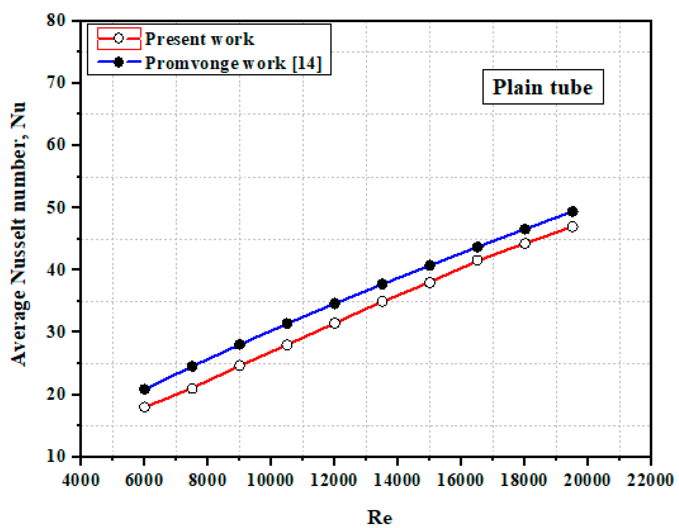
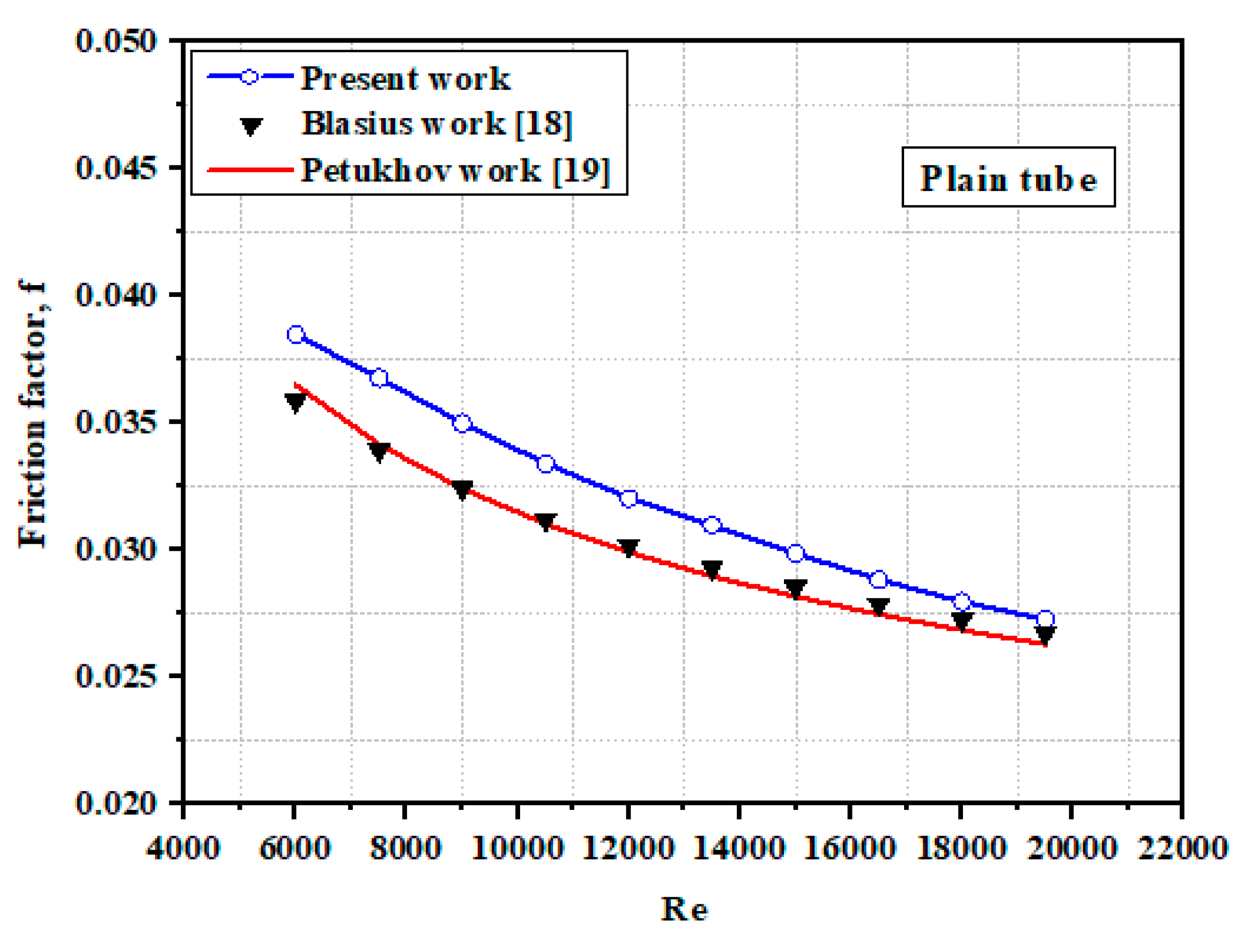
5.1. Confirmation of the Plain Heat Exchanger Findings

The findings of the linked experiment’s heat transfer were referred to as the (Nu), while the results of the friction losses were referred to as the (f). Prior to conducting the tests, the Nu and f values of the heat exchanger without inserts were recorded and verified to assess the reliability of the measurement and test equipment over the entire test range. The Nu and f findings were compared to previous empirical correlations of Promvonge [27] for Nu number and Blasius [36] and Petkhov [37] for f under comparable conditions, as shown in Figure 4 and Figure 5, respectively. These findings show that the Nu and f values match well to values derived from prior empirical correlations available within 5.4 percent and 4.47 percent, respectively.

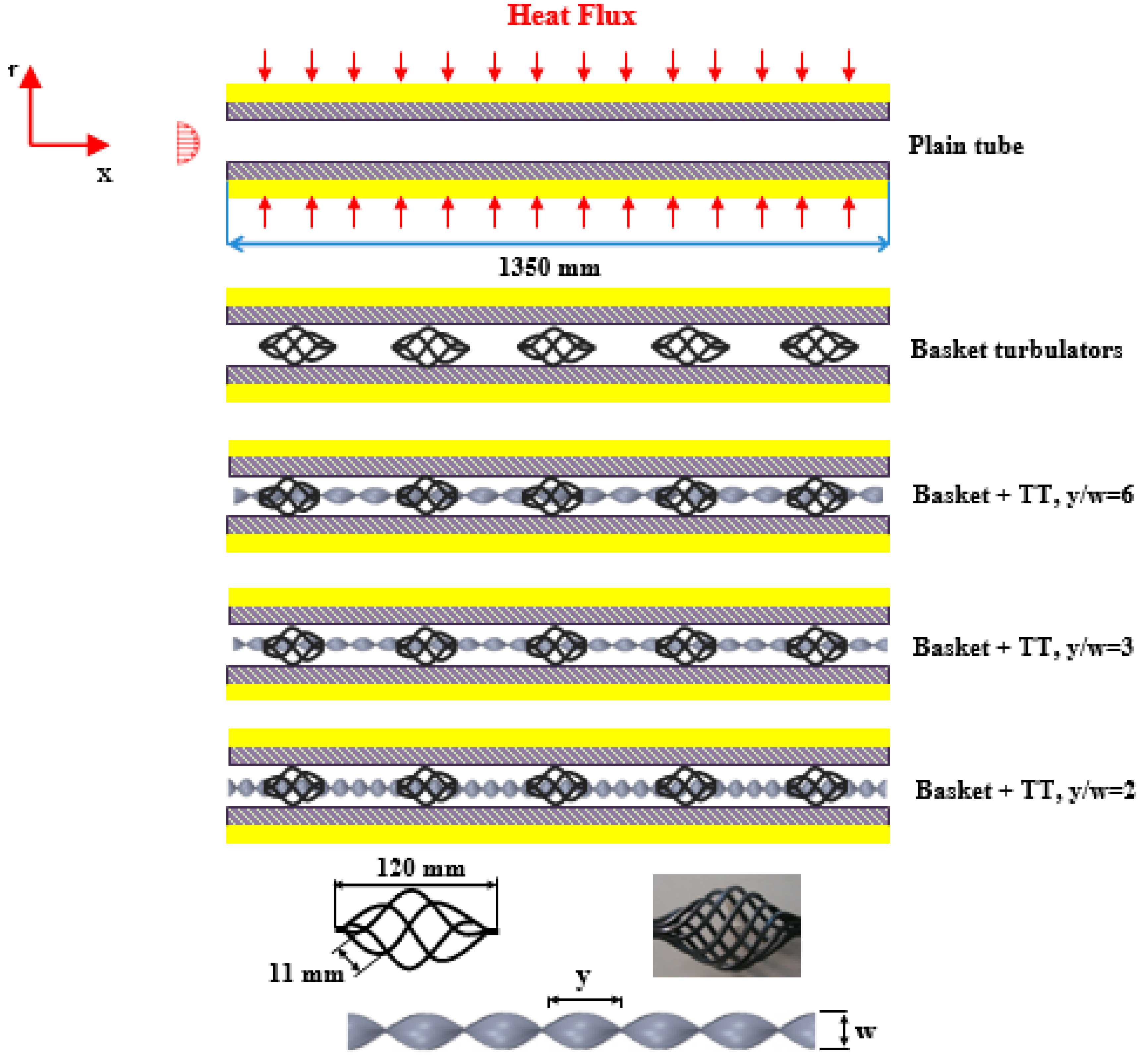
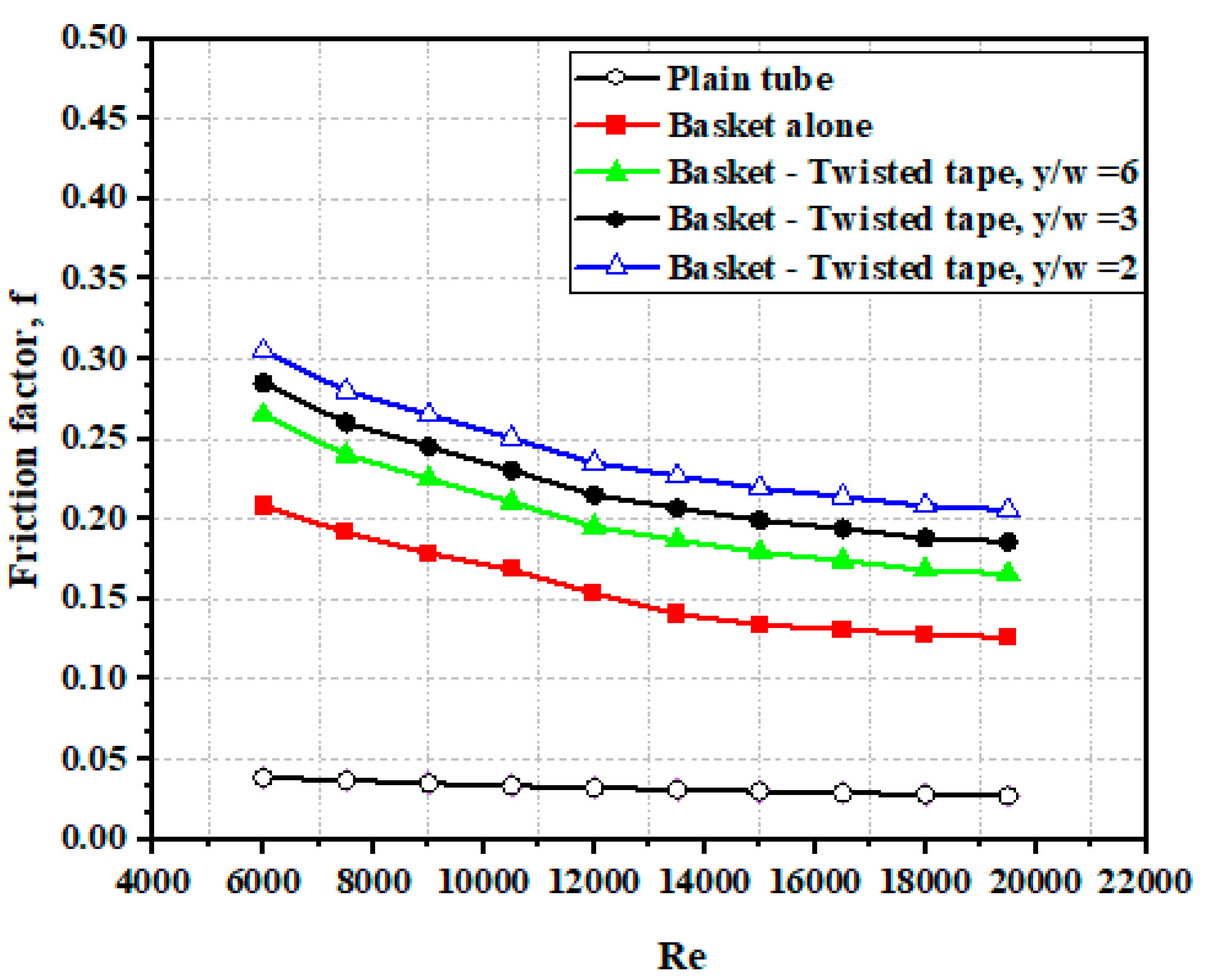
5.2. Impact of Combined Basket–Twisted Tape Inserts

Figure 6 depicts the impact of the basket and combination basket–twisted tape inserts on heat transfer rate. The average Nu and Re numbers were noted to be directly related to each other. This might be related as the turbulence intensity goes up with rising Re, which resulted in an increase in convective heat transfer. The use of basket turbulators alone resulted in a considerable increase in heat transmission rate with variation in Re. The average Nu of the basket turbulators was found to be around 131.8 percent greater than that of the ordinary heat exchanger for constant pitch ratio (PR = 150 mm). The reason for this might be related to the heat exchanger creating a spiral or secondary flow with relatively high turbulent intensity, which leads to the disruption and reintegration of the thermal boundary layer, which further improves the convection heat transfer and momentum process. Using twisted-tape in combination with basket turbulators results in stronger swirl flow around the core region and more mixing occurring within the heat exchanger core and the wall region, which is why the average Nu is higher than that of basket turbulators alone. Figure 6 shows that when the combined basket–twisted tape is introduced with a rising Re number and decreasing twist ratio, the average Nusselt number increases. Due to the increased turbulence intensity and longer flow length with a low twist ratio (y/w = 2), the greatest heat transfer rate was attained. The average Nu of the combined basket–twisted tape inserts was increased by 169.5 percent, 187.7 percent, and 206.5 percent for y/w = 6, 3, and 2, respectively, when compared to the simple heat exchanger. Figure 7 depicts the fluctuation of the f with the Re number. The employment of basket and coupled basket–twisted tape inserts results in an extra pressure loss when compared to the basic heat exchanger, as predicted. The dissipation of dynamic pressure owing to increased forces generated by swirling flow, as well as the increase in air contact surface area induced by the presence of basket–twisted tape inserts, account for a major portion of the pressure loss. The f of basket turbulators can be up to three and a half times that of a conventional heat exchanger, while the variation in friction factors induced by differing twist ratios might be up to 5–6.5 times greater.

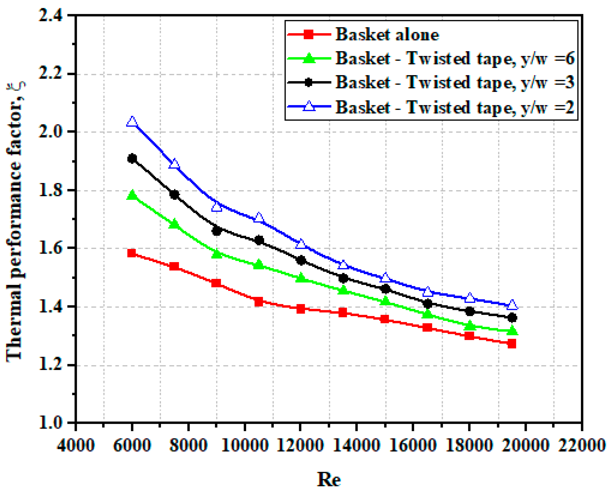
5.3. Thermal Performing Assessment

Figure 8 illustrates the fluctuation of thermal performance factor (ξ), computed by Equation (10), with Re number. It is evident that the thermal efficiency reduces with the rising Re number and increases with the use of basket and combination basket–twisted tape inserts, notably in the 6000–12,000 Re number range. It is worth mentioning that the case of combined basket–twisted tape with a modest twist ratio outperforms those with a greater twist ratio and the case of basket alone in terms of thermal performance. Figure 9 compares all of the evaluated instances and their influence on the thermal performance factor. When basket and combination basket–twisted tape inserts with N = 5 and y/w = 6, 3, and 2 are used, the average thermal performance factor is 1.40, 1.49, 1.56, and 1.63 times, respectively.

5.4. Empirical Correlations

Using coupled basket–twisted tape inserts with y/w = 6, 3, and 2, empirical correlations were generated for turbulent flow regimes with Re numbers ranging between 6000–19,500. The Nu and f of the plain heat exchanger were correlated based on the experimental results and are provided below in Equations (15) and (16), respectively [37,38].
N u = 0.0158 R e 0.825 P r 0.4
f = 0.5229 R e 0.298
Correlations depending on (Re), (Re), Prandtl number (Pr), number of basket inserts (N), and twist ratio (y/w) were suggested for the case of combined basket–twisted tape inserts as follows [37,38]:
N u = 0.11618 R e 0.625 P r 0.4 N 0.541 ( y / w ) 0.011
f = 0.6284 R e 0.285 N 0.99 ( y / w ) 0.0001
The predicted values of the Nu were found to be within 7.2 percent of the experimental data for the average Nu, as shown in Figure 10.

6. Conclusions

The heat transfer and pressure drops of a circular heat exchanger with a basket and combined basket–twisted inserts are investigated using three types of twist ratios (TR = 2, 3, and 6) in a turbulent flow condition with Re values varying between 6000–19,500. The experimental findings show that using combination basket–twisted tape inserts generates greater heat transfer rates than using a basket alone in a heat exchanger.
For y/w = 6, 3, and 2, the greatest rate of heat transfer attained by utilizing the combination basket–twisted tape improved by 169.5, 187.7, and 206.5 percent, respectively, as compared to the simple heat exchanger. For y/w = 6, 3, and 2, the thermal performance factor attained by employing the combination basket–twisted tape inserts improved by 1.49, 1.56, and 1.63 times, respectively, in comparison with the simple heat exchanger.

Author Contributions

Data curation, H.Q.A.K., S.S.A. and F.A.; Formal analysis, S.S.A. and W.A.K.A.-M.; Investigation, H.Q.A.K., H.A.A.W. and S.S.A.; Methodology, H.A.A.W. and W.A.K.A.-M.; Supervision, B.E.; Visualization, H.A.A.W. and F.A.; Writing—original draft, H.Q.A.K. and W.A.K.A.-M. All authors have read and agreed to the published version of the manuscript.

Funding

This research received no external funding.

Acknowledgments

We acknowledge support by the Deutsche Forschungsgemeinschaft (DFG) German Research Foundation and the Open Access Publishing Fund of the Technical University of Darmstadt. The authors would like to also thank the University of Technology- Iraq.

Conflicts of Interest

The authors declare no conflict of interest.

Nomenclature

AttInner Surface Area of tube Test Section, m2
Cp.aSpecific Heat of Air, J/kg.K
DHydraulic Diameter, m
fFriction Factor
h ˙ Coefficient of Heat Transfer, W/m2.K
ICurrent, A
VVoltage, volt
KaThermal Conductivity, W/m.K
LLength of Tube Test Section, m
m ˙ aAir Mass Flow Rate, kg/s
NNumber of Turbulators pieces
NudAverage Nusselt Number of Plain tube Case
PrPrandtl Number
Q l o s Heat losses, W
Q c o n . Convective Heat Transfer from the Test Section, W
ReReynolds Number
Tb,ITemperature of Air at the Test Section Entrance, °K
Tb,oTemperature of Air at the Test Section Exit, °K

References

  1. Yakut, K.; Sahin, B. Flow-induced vibration analysis of conical rings used for heat transfer enhancement in heat exchangers. Appl. Energy 2004, 78, 273–288. [Google Scholar] [CrossRef]
  2. Mashayekhi, R.; Khodabandeh, E.; Bahiraei, M.; Bahrami, L.; Toghraie, D.; Akbari, O.A. Application of a novel conical strip insert to improve the efficacy of water–Ag nanofluid for utilization in thermal systems: A two-phase simulation. Energy Convers. Manag. 2017, 151, 573–586. [Google Scholar] [CrossRef]
  3. Gravndyan, Q.; Akbari, O.A.; Toghraie, D.; Marzban, A.; Mashayekhi, R.; Karimi, R.; Pourfattah, F. The effect of aspect ratios of rib on the heat transfer and laminar water/TiO2 nanofluid flow in a two-dimensional rectangular microchannel. J. Mol. Liq. 2017, 236, 254–265. [Google Scholar] [CrossRef]
  4. Wahhab, H.A.A.; Al-Maliki, W.A.K. Application of a Solar Chimney Power Plant to Electrical Generation in Covered Agri-cultural Fields. In IOP Conference Series: Materials Science and Engineering; IOP Publishing: Kerbala, Iraq, 2020; p. 012137. [Google Scholar]
  5. Nouri-Borujerdi, A.; Nakhchi, M. Heat transfer enhancement in annular flow with outer grooved cylinder and rotating inner cylinder: Review and experiments. Appl. Therm. Eng. 2017, 120, 257–268. [Google Scholar] [CrossRef]
  6. Khoshvaght-Aliabadi, M.; Zangouei, S.; Hormozi, F. Performance of a plate-fin heat exchanger with vortex-generator channels: 3D-CFD simulation and experimental validation. Int. J. Therm. Sci. 2015, 88, 180–192. [Google Scholar] [CrossRef]
  7. Mamourian, M.; Shirvan, K.M.; Mirzakhanlari, S.; Rahimi, A. Vortex generators position effect on heat transfer and nanofluid homogeneity: A numerical investigation and sensitivity analysis. Appl. Therm. Eng. 2016, 107, 1233–1247. [Google Scholar] [CrossRef]
  8. Sawhney, J.; Maithani, R.; Chamoli, S. Experimental investigation of heat transfer and friction factor characteristics of solar air heater using wavy delta winglets. Appl. Therm. Eng. 2017, 117, 740–751. [Google Scholar] [CrossRef]
  9. Al-Maliki, W.A.K.; Al-Khafaji, H.M.H.; Alobaid, F.; Epple, B. Design and Implementation of the Solar Field and Thermal Storage System Controllers for a Parabolic Trough Solar Power Plant. Appl. Sci. 2021, 11, 6155. [Google Scholar] [CrossRef]
  10. Chamoli, S.; Lu, R.; Xie, J.; Yu, P. Numerical study on flow structure and heat transfer in a circular tube integrated with novel anchor shaped inserts. Appl. Therm. Eng. 2018, 135, 304–324. [Google Scholar] [CrossRef]
  11. Ibrahim, M.; Essa, M.; Mostafa, N. A computational study of heat transfer analysis for a circular tube with conical ring turbulators. Int. J. Therm. Sci. 2019, 137, 138–160. [Google Scholar] [CrossRef]
  12. Xu, Y.; Islam, M.; Kharoua, N. Experimental study of thermal performance and flow behaviour with winglet vortex generators in a circular tube. Appl. Therm. Eng. 2018, 135, 257–268. [Google Scholar] [CrossRef]
  13. Chamoli, S.; Lu, R.; Yu, P. Thermal characteristic of a turbulent flow through a circular tube fitted with perforated vortex generator inserts. Appl. Therm. Eng. 2017, 121, 1117–1134. [Google Scholar] [CrossRef]
  14. Nakhchi, M.; Esfahani, J. Numerical investigation of different geometrical parameters of perforated conical rings on flow structure and heat transfer in heat exchangers. Appl. Therm. Eng. 2019, 156, 494–505. [Google Scholar] [CrossRef]
  15. He, Y.; Liu, L.; Li, P.; Ma, L. Experimental study on heat transfer enhancement characteristics of tube with cross hollow twisted. Appl. Therm. Eng. 2018, 131, 743–749. [Google Scholar] [CrossRef]
  16. Bhuiya, M.; Roshid, M.; Talukder, M.; Rasul, M.; Das, P. Influence of perforated triple twisted tape on thermal performance characteristics of a tube heat exchanger. Appl. Therm. Eng. 2020, 167, 114769. [Google Scholar] [CrossRef]
  17. Bhuiya, M.; Azad, A.; Chowdhury, M.; Saha, M. Heat transfer augmentation in a circular tube with perforated double counter twisted tape inserts. Int. Commun. Heat Mass Transf. 2016, 74, 18–26. [Google Scholar] [CrossRef]
  18. Piriyarungrod, N.; Kumar, M.; Thianpong, C.; Pimsarn, M.; Chuwattanakul, V.; Eiamsa-ard, S. Intensification of thermo-hydraulic performance in heat exchanger tube inserted with multiple twisted-tapes. Appl. Therm. Eng. 2018, 136, 516–530. [Google Scholar] [CrossRef]
  19. Khoshvaght-Aliabadi, M.; Feizabadi, A. Performance intensification of tubular heat exchangers using compound twisted-tape and twisted-tube. Chem. Eng. Process. Process. Intensif. 2020, 148, 107799. [Google Scholar] [CrossRef]
  20. Salam, B.; Biswas, S.; Saha, S.; Bhuiya, M.M.K. Heat Transfer Enhancement in a Tube using Rectangular-cut Twisted Tape Insert. Procedia Eng. 2013, 56, 96–103. [Google Scholar] [CrossRef] [Green Version]
  21. Nanan, K.; Thianpong, C.; Promvonge, P.; Eiamsa-ard, S. Investigation of heat transfer enhancement by perforated helical twisted-tapes. Int. Commun. Heat Mass Transf. 2014, 52, 106–112. [Google Scholar] [CrossRef]
  22. Ibrahim, E.Z. Augmentation of laminar flow and heat transfer in flat tubes by means of helical screw-tape inserts. Energy Convers. Manag. 2011, 52, 250–257. [Google Scholar] [CrossRef]
  23. Pal, S.; Saha, S.K. Laminar fluid flow and heat transfer through a circular tube having spiral ribs and twisted tapes. Exp. Therm. Fluid Sci. 2015, 60, 173–181. [Google Scholar] [CrossRef]
  24. Abed, A.H.; Hussein, N.F.; Abdulmunem, A.R. Effect of V-Shape Twisted Jaw Turbulators on Thermal Performance of Tube heat exchanger: An Experimental Study. Eng. Technol. J. 2018, 36, 1158–1164. [Google Scholar]
  25. Wijayanta, A.T.; Aziz, M.; Kariya, K.; Miyara, A. Numerical study of heat transfer enhancement of internal flow using double-sided delta-winglet tape insert. Energies 2018, 11, 3170. [Google Scholar] [CrossRef] [Green Version]
  26. Murugesan, P.; Mayilsamy, K.; Suresh, S. Heat Transfer and Friction Factor Studies in a Circular Tube Fitted with Twisted Tape Consisting of Wire-nails. Chin. J. Chem. Eng. 2010, 18, 1038–1042. [Google Scholar] [CrossRef]
  27. Promvonge, P.; Eiamsaard, S. Heat transfer behaviors in a tube with combined conical-ring and twisted-tape insert. Int. Commun. Heat Mass Transf. 2007, 34, 849–859. [Google Scholar] [CrossRef]
  28. Eiamsa-ard, S.; Nivesrangsan, P.; Chokphoemphun, S.; Promvonge, P. Influence of combined non-uniform wire coil and twisted tape inserts on thermal performance characteristics. Int. Commun Heat Mass Transf. 2010, 37, 850–856. [Google Scholar] [CrossRef]
  29. Kurnia, J.C.; Chaedir, B.A.; Sasmito, A.P. Laminar convective heat transfer in helical tube with twisted tape insert. Int. J. Heat Mass Transfer. 2020, 150, 119309. [Google Scholar] [CrossRef]
  30. Kurnia, J.C.; Chaedir, B.; Wijayanta, A.T.; Sasmito, A.P. Convective Heat Transfer Enhancement of Laminar Herschel–Bulkley Non-Newtonian Fluid in Straight and Helical Heat Exchangers with Twisted Tape Inserts. Ind. Eng. Chem. Res. 2021, 61, 814–844. [Google Scholar] [CrossRef]
  31. Al-Maliki, W.A.K.; Al-Hasnawi, A.G.T.; Wahhab, H.A.A.; Alobaid, F.; Epple, B. A Comparison Study on the Improved Operation Strategy for a Parabolic Trough Solar Power Plant in Spain. Appl. Sci. 2021, 11, 9576. [Google Scholar] [CrossRef]
  32. Tamna, S.; Yingyong, K.; Sompol, S.; Pongjet, P. Heat transfer enhancement in tubular heat exchanger with double V-ribbed twisted-tapes. Case Stud. Therm. Eng. 2016, 7, 14–24. [Google Scholar] [CrossRef] [Green Version]
  33. Bucak, H.; Yılmaz, F. The current state on the thermal performance of twisted tapes: A geometrical categorisation approach. Chem. Eng. Process. Process. Intensif. 2020, 153, 107929. [Google Scholar]
  34. Abernethy, B.; Benedict, R.P.; Dowdell, R.B. ANSI/ASME. In Measurement Uncertainty; University of Rhode Island: Kingston, RI, USA, 1985; Volume 107, pp. 161–164. [Google Scholar]
  35. Kline, S.J.; McClintock, F.A. Describing uncertainties in single sample experiments. Mech. Eng. 1953, 75, 385–387. [Google Scholar]
  36. Man, C.; Lv, X.; Hu, J.; Sun, P.; Tang, Y. Experimental study on effect of heat transfer enhancement for single-phase forced convective flow with twisted tape inserts. Int. J. Heat Mass Transf. 2017, 106, 877–883. [Google Scholar] [CrossRef]
  37. Incropera, F.; Dewitt, P.D. Introduction to Heat Transfer, 3rd ed.; John Wiley & Sons Inc: New York, NY, USA, 1996. [Google Scholar]
  38. Al-Maliki, W.A.K.; Alobaid, F.; Keil, A.; Epple, B. Dynamic Process Simulation of a Molten-Salt Energy Storage System. Appl. Sci. 2021, 11, 11308. [Google Scholar] [CrossRef]
Figure 1. Photographic view of the using experimental apparatus.
Applsci 12 04807 g001
Figure 2. Schematic of the using experimental apparatus.
Applsci 12 04807 g002
Figure 3. Geometric configurations of twisted tapes.
Applsci 12 04807 g003aApplsci 12 04807 g003b
Figure 4. Confirmation of Nusselt number for plain heat exchanger.
Applsci 12 04807 g004
Figure 5. Confirmation of friction factor for plain heat exchanger.
Applsci 12 04807 g005
Figure 6. Difference of Nusselt number and Re number for heat exchanger trim by basket alone and combined basket–twisted tape inserts.
Applsci 12 04807 g006
Figure 7. Difference of friction factor with and Reynolds number for heat exchanger trim by basket alone and combined basket–twisted tape inserts.
Applsci 12 04807 g007
Figure 8. Variation of thermal performance factor with Reynolds number for heat exchanger fitted with basket alone and combined basket–twisted tape inserts.
Applsci 12 04807 g008
Figure 9. Percentage of thermal performance factor enhancement.
Applsci 12 04807 g009
Figure 10. Expected data of Nu vs. trial data.
Applsci 12 04807 g010
Table 1. Thermocouple’s location.
No.123456789101112131415161718
Position-x-(mm)10203050709013017023029038047057067077090010401180
Table 2. Accuracy of Measurement Instruments.
Measured ParametersValue
Temperature ±   0.5   ° C  
Air velocity ± 0.75   m / s  
Current of the heater ± 0.0003   Amp  
Voltage of the heater 0.04   Vol
Publisher’s Note: MDPI stays neutral with regard to jurisdictional claims in published maps and institutional affiliations.

