Article

Characteristics of Dynamic Safety Factors during the Construction Process for a Tunnel-Group Metro Station

1
China Railway Liuyuan Group Co., Ltd., Tianjin 300308, China
2
College of Civil Engineering, Tongji University, Shanghai 200092, China
3
State Key Laboratory for Disaster Reduction in Civil Engineering, Tongji University, Shanghai 200092, China
*
Authors to whom correspondence should be addressed.
Appl. Sci. 2022, 12(10), 4900; https://doi.org/10.3390/app12104900
Submission received: 26 March 2022 / Revised: 7 May 2022 / Accepted: 10 May 2022 / Published: 12 May 2022
(This article belongs to the Special Issue Advances in Developing Underground)

Abstract

:
Dynamic safety factors during the construction of an overlapping tunnel-group metro station were studied in the framework of the strength-reduction finite element method. Based on the equivalent plastic strain and displacement of surrounding rock, its damage mode under typical excavation conditions was investigated. The aim of this investigation was to provide information for the design activities concerning the supporting system of the station and the pre-reinforcement of its surrounding ground. The accuracy of the model was assessed by comparing the ground settlements obtained from on-site monitoring with those from the numerical model. The analysis results show that the safety factor reaches the minimum when the No. 3 guide hole of the station hall is excavated. Thus, this is the most dangerous construction step. During this step, the plastic zone penetration phenomenon occurs in the surrounding rock, which is sandwiched between the hall and the platform of the station. In this case, both the deformation of the surrounding rock and the internal forces of the lining increase. The surrounding rock in the sidewall loses its stability. Thereafter, the primary support plays a role of stabilizing the guide hole.

1. Introduction

In the stability analysis of tunnels, the most commonly used method is FEM simulation [1,2,3]. One of the most important problems in the structural calculation of tunnels is how to estimate the stability of the rock mass surrounding the tunnel.
Due to the lack of a reasonable criterion for evaluating the stability of tunnels [4,5,6,7], a unified safety factor of the tunnel had not yet been defined in previous studies that used FEM simulations for the excavation of tunnels. The stability of the surrounding rock is generally classified according to experience. Tunnel construction monitoring and measurement has become an important method to evaluate the stability of tunnel construction at present [8,9], because it can provide timely feedback on the deformation and stress during the tunnel construction process. Due to the complexity of the tunnel construction process and the geological conditions, there are limitations in using the permissible displacement of the surrounding rock as the basis of tunnel stability in the monitoring and measurement [10,11,12]; therefore, it is very important to carry out research on the analysis and control of tunnel construction stability. In this paper, the finite element strength-reduction method is introduced into the tunnel construction stability analysis, and the dynamic evaluation of the whole process of surrounding rock stability in the construction stage based on the safety factors is proposed.
In 1975, Zienkiewice [13] from the University of Wales proposed a strength-reduction method (SRM) by finite element analysis, and some scholars studied slope stability analysis using this method [14,15,16,17,18,19,20]. By reducing calculation parameters, the ultimate state of the slope could be reached, and the safety factor could be determined. Many scholars have improved the strength reduction method, such as: Yuan and Bai [21,22], Zhang [23], Jong [24], Sun [25], Huang [26], and Wang et al. [27]
Zheng et al. [28] applied the SRM in tunnels and underground engineering for the first time. Shiau and Al-Asadi [29] investigated the face stability of twin circular tunnels horizontally aligned in cohesive undrained soil under plane strain conditions. Liang et al. [30] used a three-dimensional numerical model and the SRM in order to analyze the influence of triaxial stress states on the failure behavior and the safety factor of deep tunnels. Xia et al. [31,32] combined the discontinuous deformation analysis method, the SRM, and the catastrophe theory. They studied the stability of tunnels surrounded by rock. Pan et al. [33] estimated the safety factor of a tunnel face with a non-circular section by means of combining the upper-bound limit analysis with the strength-reduction technique. He [34] used the orthogonal test and SRM to study the stability of tunnels. Zhang et al. [23] defined the tunnel safety factor as the ratio of the actual shear strength parameter to the critical failure shear strength parameter. Chen et al. [35] used the strength-reduction method embedded in the RFPA method to achieve the gradual fracture process, macro-failure mode, and the safety factor.
At present, the research on tunnel stability mainly focuses on the stability of single tunnels [28,30,31,32]. Some of them simplify the excavation process and supporting process of the surrounding rock [23,31,32,33,34,35]. Some of them have not yet unified the criteria for discriminating tunnel stability [29]. In addition, there are few reports on the research results of the safety factor of the tunnel group during the construction period. Therefore, this paper attempts to apply SRM to the construction process of tunnel-group metro stations. It combines surrounding rock displacement and equivalent plastic strain as tunnel stability indicators to evaluate the safety factor of tunnels.
This paper takes a metro station constructed by a combination method as the background project. The station consists of a separate station hall and platform, a single-line tunnel, and a side platform. The hall floor is constructed by the arch cover method, and the platform layer is constructed by the step method. The site layer is filled with plain fill, medium-weathered granite, and micro-weathered granite from top to bottom, and is mixed with two fault fracture zones (the inclination of F4 and F4-1 is 60°). The cross-section view is shown in Figure 1. The schematic of the construction steps is shown in Figure 2. The station hall has a span of 21.1 m, height of 14.5 m, and depth of 19 m. The platform has a span of 10.6 m, height of 12.3 m, and depth of 40 m, and the thickness of the surrounding rock in the station hall and platform is 7 m. The tunnel is in the form of a composite lining structure. In order to prevent the arch of the face from collapsing, the small pipe grouting support and the side wall system anchor are used.

2. Analysis Method

2.1. Calculation Process of Strength-Reduction Finite Element Method

The strength-reduction finite element method [36] reduces the shear strength indicators, c, and tanφ of the rock by a reduction factor, ω, greater than 1, as in Equations (1) and (2):
c = c ω
φ = arctan tan φ ω
The reduction factor is substituted into the above formula and finite element calculation is performed. The reduced factor is increased until the finite element calculation does not converge. The final reduction factor is defined as the safety factor. It refers to the critical state of tunnel instability. Correlation between the convergence of the finite element calculation and the tunnel stability will be discussed in the next section.
Firstly, compared with the traditional limit equilibrium method, the SRM does not need to assume the failure surface in advance, and the situation when the plastic strain of the surrounding rock changes abruptly is the situation when the damage flow of the surrounding rock occurs, so the potential surface damage of the surrounding rock can be obtained by finding the points with the largest plastic strain value in each section of the plastic zone of the surrounding rock and connecting them in a line, and the safety factor of the underground cavern can be obtained at the same time. Secondly, the method can apply different yield criteria, which are more applicable than the limit balance method. The SRM can simulate the progressive damage process of geotechnical engineering well by continuously increasing the reduction factor.

2.2. Judgment of Tunnel Instability in Calculation

The convergence criterion of finite element calculation generally has a displacement convergence criterion, an unbalanced force convergence criterion, and an unbalanced energy convergence criterion, all using the Euclidean criterion of the vector method. In the present paper, the displacement convergence criterion is used. It is based on the ratio of the displacement incremental norm before the ith iteration to the displacement incremental norm after the ith iteration in the calculation as the convergence criterion, as in Equation (3):
δ u i k = 1 i 1 δ u k ε d
where εd is the standard limit of displacement convergence, and δuk is the displacement increment calculated by the kth iteration.
As the reduction factor, ω, is increased, Condition (3) will never be satisfied, which indicates that the finite element calculation is not converged. The mechanical essence of this numerical phenomenon is instability of the rock surrounding the tunnels.
The typical instability has two modes, i.e., local instability and overall instability. The surrounding rock damaged by the instability of the tunnel will produce an infinitely developed plastic displacement, which is manifested in the finite element calculation as the unsatisfactory calculation of the convergence criterion. At the same time, for the tunnel with an unstable state, the iterative process of the finite element will not continue because the infinitely developed plastic displacement has been generated, or the more iterative the displacement is, the more it deviates from the convergence criterion, and the final calculation does not converge [18]. It can be seen that the non-convergence of the solution is a necessary and sufficient condition for the instability of the tunnel. Therefore, the non-convergence of force and displacement is used as the criterion for tunnel instability.

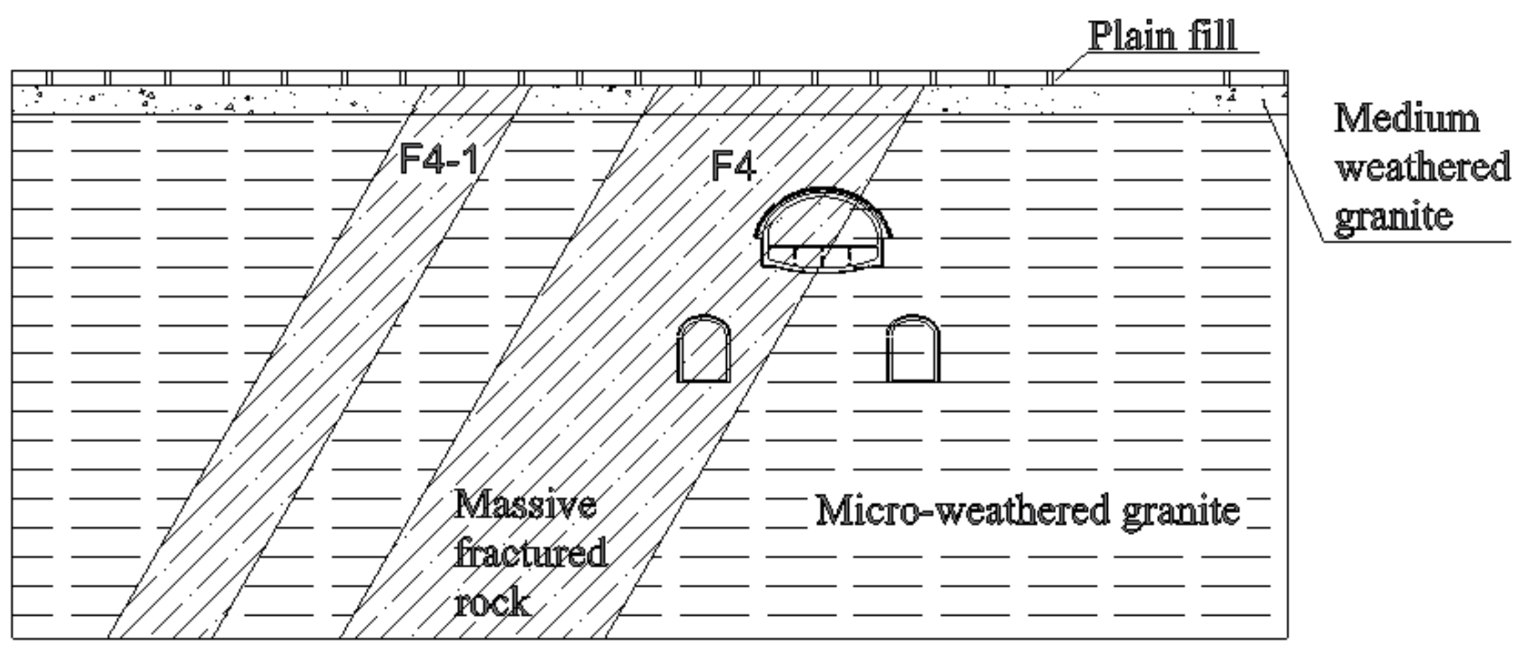
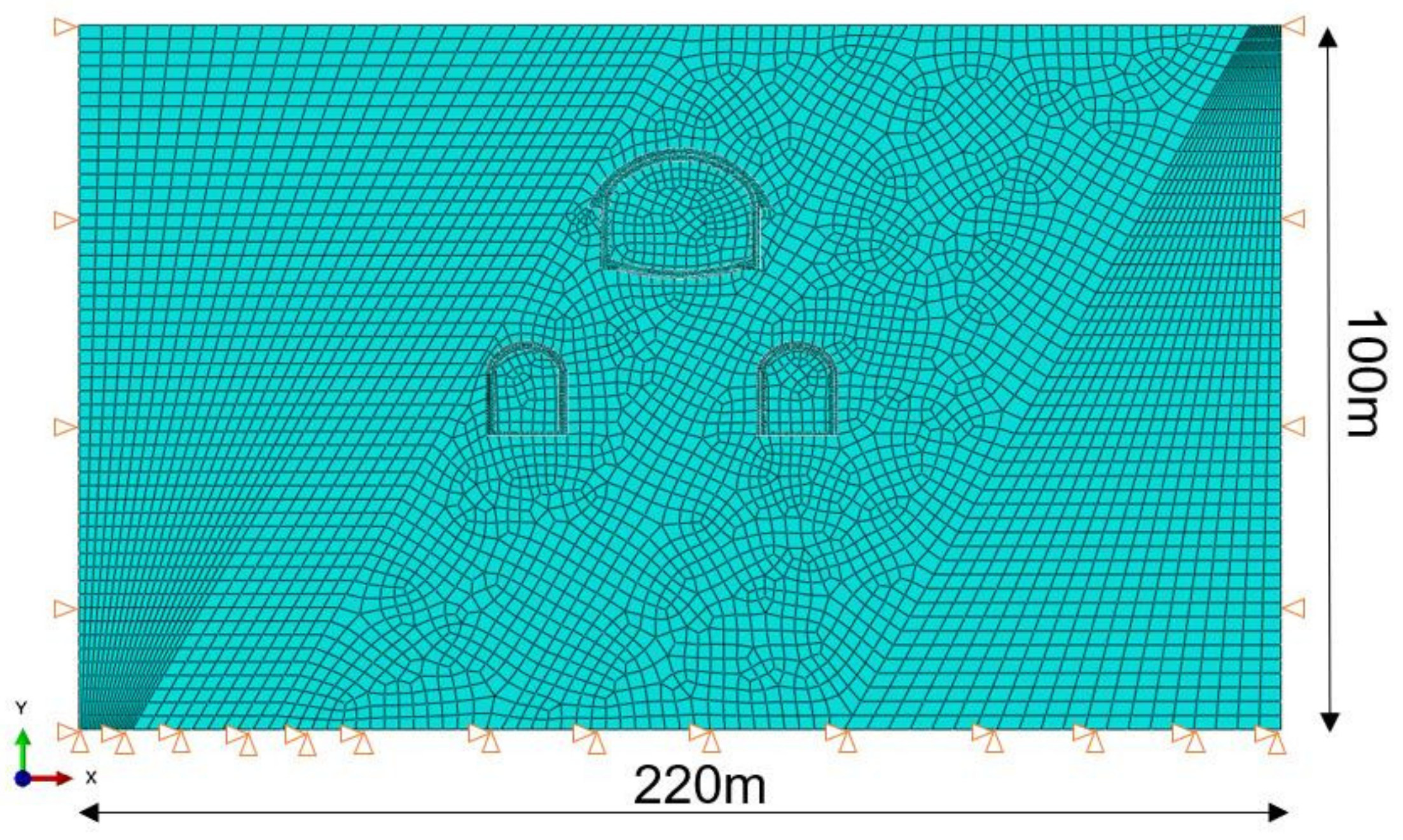
2.3. Numerical Model and Parameters
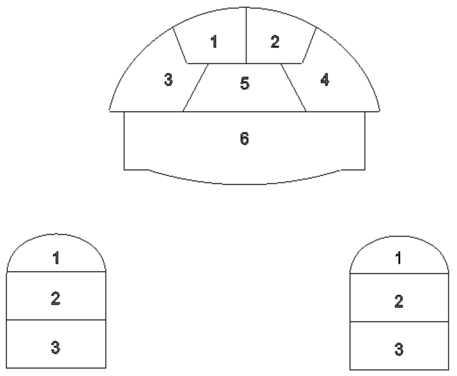
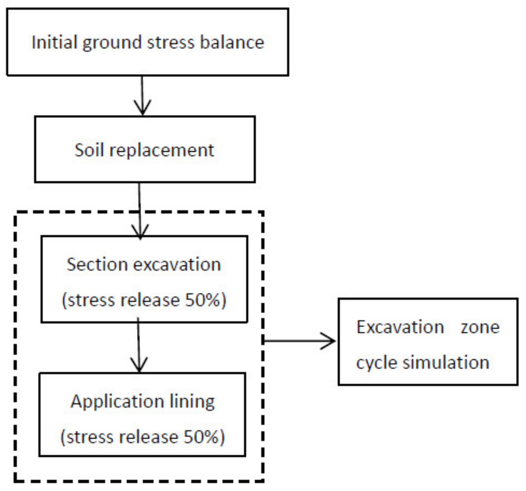
The ABAQUS software program, based on FEM, was used for simulating the process of tunnel excavation and support structure. The calculation model adopts the ideal elastoplastic model and the Mohr–Coulomb yield criterion, and is processed according to the plane strain problem. The model includes the site rock, support structure, and the reinforcement layer. Solid elements are used for both the surrounding rock and the primary lining, the secondary lining is not simulated, and only the self-weight stress is considered in the initial stress field of the surrounding rock. The finite element model is shown in Figure 3. For the selection range of the model, the upper surface is the ground surface, the bottom is greater than three times the height of the structure from the bottom of the structure, and the horizontal side is greater than three times the span of the structure from the side of the structure. Therefore, the length of the model is 220 m, and the depth is 100 m. The boundary constraints are: the left and right sides constrain the displacement in the x direction, and the bottom boundary constrains the displacement in the x and y directions.
In the finite element calculation, it can be considered that the auxiliary construction method forms a certain thickness of the reinforcement zone in the surrounding rock of the cavern [37]. Therefore, the simulation of the pre-support effect can be implemented by an equivalent method of improving the surrounding rock parameters within the reinforcement zone. The thickness of the grouting reinforcement zone was calculated as follows: Consider the case where the grouting diffusion ranges overlap each other, and first calculate the slurry diffusion radius according to Equation (4):
R = 0.6 ~ 0.7 L 0
where L0 is the center distance of the conduit, which is 0.4 m. Second, calculate the thickness of the grouting reinforcement zone according to Equation (5):
D = 2 [ R 2 ( S 2 ) 2 ] 0.5
where S is the spacing between two adjacent grouting holes, valued at 0.2 m. Finally, the thickness, D, of the grouting reinforcement zone is calculated to be 0.5 m. The research results in [38] show that the cohesive force of surrounding rock can be increased 1~2 times after grouting, and the surrounding rock can be improved by one level. Considering the geological conditions of the site, the parameters E and c in the equivalent reinforcement zone are increased 1 time in the calculation. According to the geological survey report, the site soil layer is simplified into three layers. From top to bottom are plain fill, medium-weathered granite, micro-weathered granite, and crossing the fault fracture zone. C25 concrete is used for shotcrete. The simplified physical and mechanical parameters of the rock and the initial support parameters of the shotcrete [39] are shown in Table 1.

2.4. Analysis Steps

Considering the time effect of stress release during tunnel excavation, the stress is released in two steps, i.e., the excavation and hardening of the linings. According to the suggestions provided in [37], the percentage of released stress in each step was taken as 50%. The station floor is divided into six areas, and the platform floor is divided into three areas. Both excavated the surrounding rock at the same time. The excavation sequence is as shown in Figure 2, with a total of 12 construction steps. The entire construction flow chart of the tunnel is shown in Figure 4.
Whether the surrounding rock can be self-stabilized after tunnel excavation determines whether the tunnel is safe or not, the strength-reduction finite element method is used to reduce the strength index, c, and tanφ of the rock until the calculation does not converge, and the reduction factor is the safety factor under working conditions, or the strength reserve.

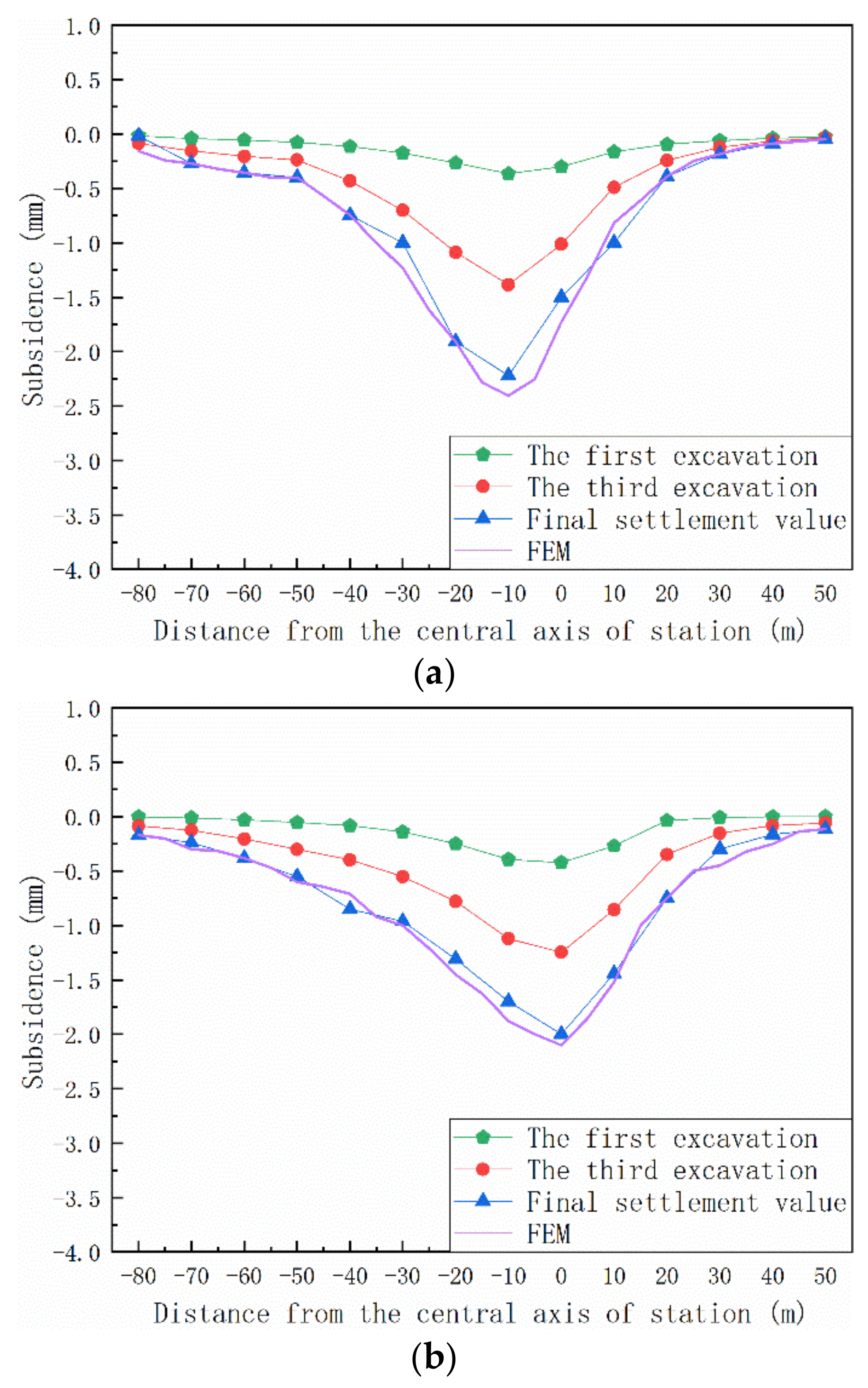
2.5. Comparison of On-Site Monitoring Results

In order to verify the accuracy of the numerical model and parameter selection, two representative sections (K1+809 section and K1+846 section) were selected for surface subsidence monitoring. The development curve of the subsidence slot curves of the two sections with the construction excavation sequence and the final settlement curve of the numerical simulation are shown in Figure 5.
Comparing the on-site monitoring data and the finite element analysis results, the surface subsidence at a distance of one-hole diameter from the station center line is about 60% of that at the center line. The third step of excavation caused a larger surface subsidence. The maximum value is less than 3 mm, the actual final settlement curve is close to the numerical simulation results, and the maximum error is less than 8%. This underlines the robustness of the proposed model because there are no fitted parameters involved in the model.

3. Dynamic Change of Safety Factor

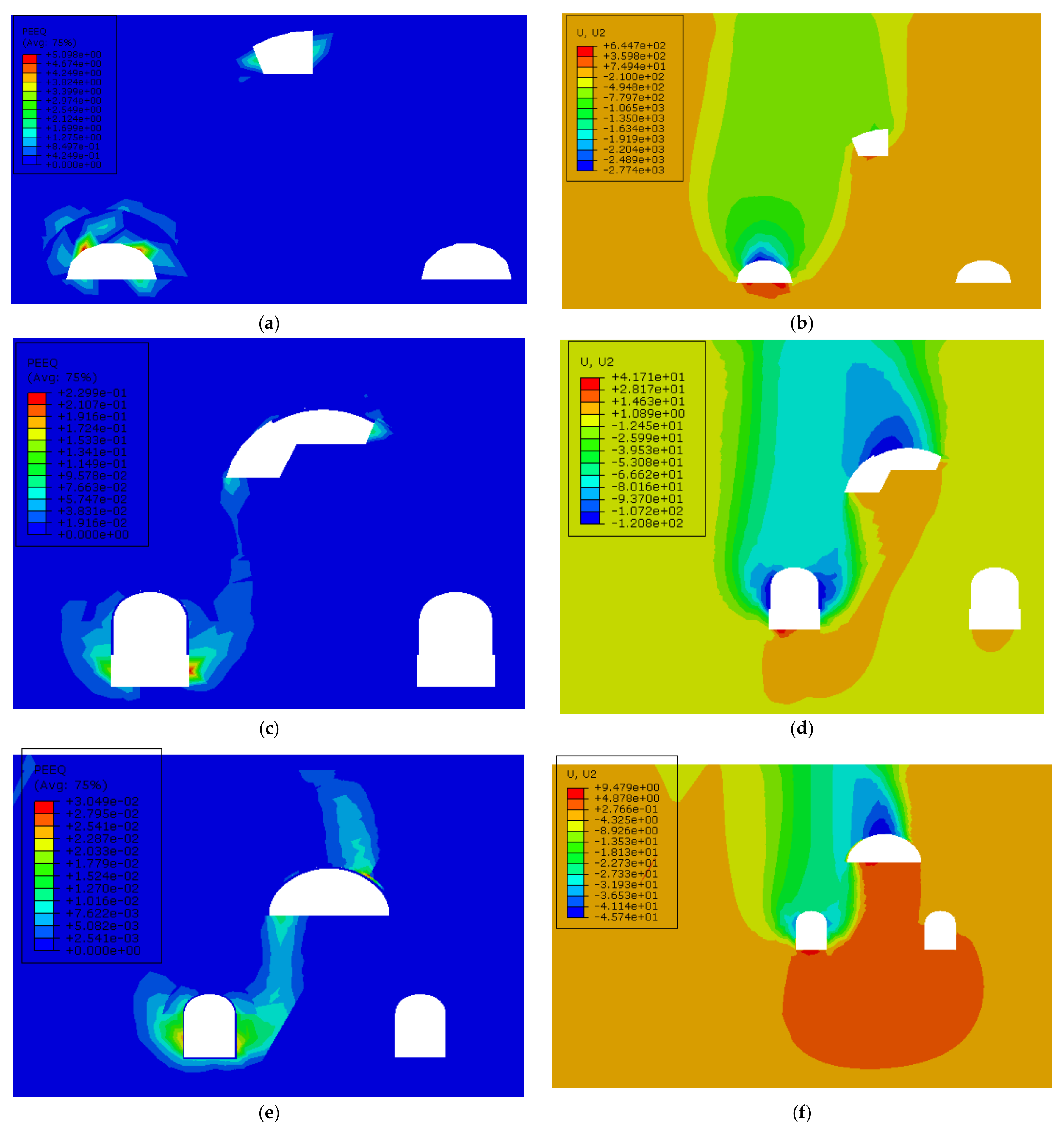
3.1. Equivalent Plastic Strain and Displacement

During the construction of a tunnel-group metro station, there are many construction procedures, and the surrounding rock and supporting structures are subject to complex stress, which is prone to stress concentration. Studying the development law of the plastic zone is the key to ensuring the stability of the surrounding rock and the safety of construction. This research selects the key construction procedures in tunnel construction, analyzes the plastic zone when its strength is reduced to failure, and studies the development law of its surrounding rock failure. Then, the model’s equivalent plastic strain and displacement diagrams of the key excavation areas 1, 3, and 5, when the surrounding rock strength is reduced to failure, are shown in Figure 6. It was found that non-convergent computations are associated with a sudden change of displacement of the rock surrounding the excavated areas 1 and 3, respectively. A non-convergent computation is associated with a connected plastic zone, as excavation of area 5 is completed.
Different from the shallow tunnel’s damage area in the tunnel vault, in the process of deep tunnel excavation, the tunnel damage generally starts from both side walls of the tunnel body. Whether the surrounding rock of the tunnel can remain stable after the excavation is completed determines the safety of the structure. Comparing the equivalent plastic strain and model displacement of each excavation step, in excavation area 1, the insufficient strength of the surrounding rock will cause instability of the roof of the platform floor, resulting in large settlement of the surface. When excavating area 3, the equivalent plastic strain area of the surrounding rock sandwiched between the platform and the station hall will appear to be connected, and the plastic zone is further increased. At this time, the failure zone is on the lower steps of the left platform, and the surrounding rock failure zone has not yet penetrated the surface. Excavation area 5 is the excavation of the upper core rock, and damage will occur at the vault of the station floor. The surrounding rock from the vault to the surface produces a large plastic strain zone, and the plastic zone of the surrounding rock between the station hall and the platform extends further. However, the overall collapse of the tunnel will not occur. In this case, since the primary lining of the platform floor has been closed, it has not been damaged. It can be seen that the primary lining has a great effect on stabilizing the surrounding rock.

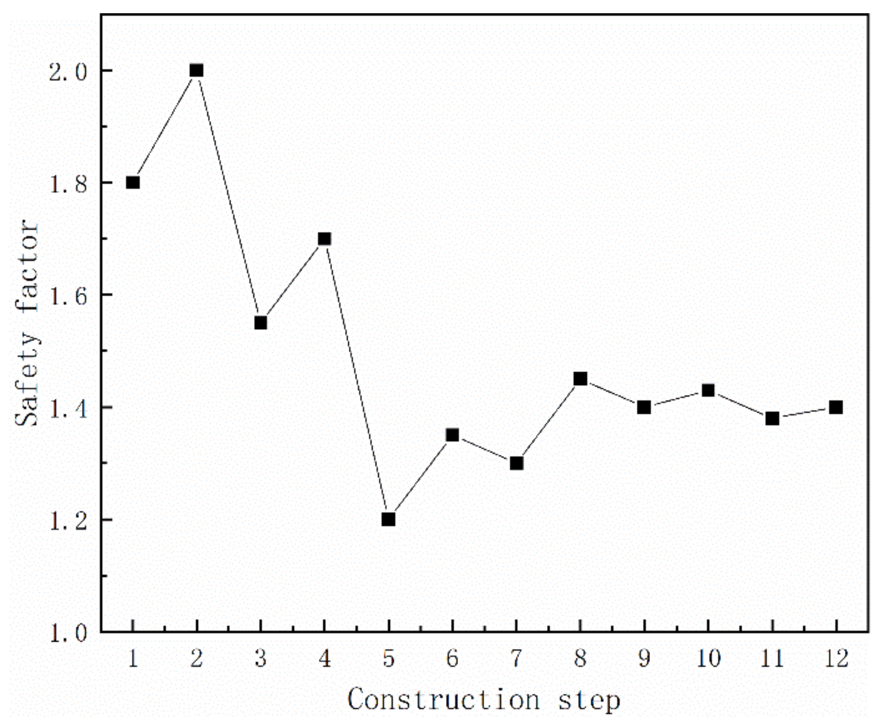
3.2. Safety Factor of the Construction Step and Key Working Conditions

The strength-reduction calculation was carried out for the six construction areas of the tunnel in the excavation and support states, respectively, and the change in the safety factor of the corresponding load step was obtained, as shown in Figure 7.
The safety factor for the first construction step, referring to the excavation of area 1, was equal to 1.83. It was increased to 2.01, because of the supporting effect of the hardening lining of the excavated area 1 in the second construction step. For the third step, i.e., excavation of area 2, the safety factor was reduced to 1.55. It was increased to 1.70 due to the supporting effect of the lining in the fourth step. In the fifth construction step, i.e., excavation of area 3, the safety factor was reduced to the minimum of 1.20. Thereafter, the application of the lining raised the safety factor for the sixth step to 1.35. In the fourth cycle, the seventh step referred to excavation of area 4. At that moment, the safety factor was equal to 1.30. After applying the lining, it was increased to 1.47 in the eighth step. When it comes to the ninth step, i.e., excavation of core soil area 5, the safety factor was equal to 1.40. It was increased to 1.42 in the tenth step. Finally, the safety factor for excavation of area 6, corresponding to the eleventh step, was equal to 1.38. After the lining was made into a ring in the twelfth step, the safety factor was increased to 1.40. The trend of the change in the safety factor decreased as the area of the excavation increased. Among them, the safety factor was the smallest when excavating the No. 3 guide hole (excavation area 3), which was 1.20, so it was the key working condition in the tunnel construction process. During the excavation of the tunnel excavation areas 4, 5, and 6, the safety factor did not change much. Comparing the changes in the safety factors of a complete excavation process, it can be seen that the minimum safety factor is that when the excavation is not supported, and the initial support can improve the safety factor. For the excavation section of the entire tunnel-group, since the initial support of the platform is closed, the excavation of this part has less impact on the safety of the tunnel when the lower part of the station floor is excavated. The excavation safety factor of the whole tunnel-group indicates that the working condition with the smallest safety factor was the excavation of area 3. Therefore, areas 1, 3, and 5 were selected for in-depth analysis. The safety factor and instability form of the selected working conditions are shown in Table 2.
According to the research on the dynamic evolution law of the surrounding rock stability during the construction stage, the stability–safety factor of the surrounding rock changes with the construction process. It has been shown that this factor was always larger than 1.20 over the entire construction period. Notably, this is consistent with the recommendation that the stability safety factor of surrounding rock after initial support must be larger than 1.20, see, e.g., [40,41].
The instability forms of excavation areas 1 and 5 are both partial collapse of the roof. When excavating area 3, the surrounding rock strength was reduced until failure, which occurs when the side wall of the left platform collapses. For deep-buried tunnels, local small-scale instability does not pose a major threat to the overall safety of the tunnel; however, in urban metros, local instability does not cause overall damage to the tunnel, but it leads to excessive ground settlement that is not allowed by the regulations. The magnitude of the increase in the safety factor after the support of area 3 was the largest, indicating that the initial support of the arch can significantly improve the overall stability of the tunnel. Therefore, for the unstable form that may be caused by insufficient strength of the surrounding rock, proper pre-reinforcement should be conducted before excavation, and the initial support should be applied as soon as possible after excavation.
The safety factor of excavation area 3 was 1.20, and this step was the most dangerous construction step in the whole construction process. After discounting the strength of the surrounding rock, a through plastic zone will appear from the station floor and platform, a large plastic zone will appear on the lower platform of the station, and the lower platform of the station will collapse. Comparing the excavation areas 3 and 1, the former is large, the distance between the surrounding rock of the station hall and the platform is smaller, and area 3 is located in the fault fracture zone. These factors affect the safety factor when excavating in this area. Therefore, the actual design of the tunnel should be carefully selected to cross the stratum, and it is necessary to consider expanding the pre-reinforcement of the weak surrounding rocks.

4. Conclusions

In this paper, the finite element strength-reduction method, which is widely used in slope stability analysis, was introduced into the stability study of tunnel excavation. The arch cover method was selected as the representative excavation method. For the damage characteristics of a tunnel-group, the safety factors of the tunnels after excavation of the areas 1, 3, and 5 were selected for the study. The calculated conditions refer to the moment when the excavation of each part is completed but before it is supported. The following conclusions were drawn from the present study.
(1)
When the finite element strength-reduction method was used for the analysis of the stability of the surrounding rock, a judgment method based on the convergence of the finite element calculation could be adopted, since the non-convergence is associated with either local instability of the rock surrounding the excavation area or overall instability of the rock of the connected plastic zones.
(2)
For the form of instability under each working condition, designers should carefully select the crossing stratum of the tunnel vault and pay attention to the pre-reinforcement of the surrounding rock of the vault before construction. Pre-reinforcement approaches may include expanding the scope of the reinforcement area or increasing the reinforcement strength.
(3)
For a large-span concealed tunnel, the initial support should be implemented in time. After the arch is excavated, the initial support of the section should be closed early.
(4)
For this tunnel-group metro station, excavating in area 3 was the most dangerous construction step. The application of initial support in each excavation step will increase the safety factor of the surrounding rock to different degrees.
There is no doubt that the SRM has wide applicability, and the results obtained in this case were only used for special tunnel structures. In the future, additional analyses are planned to perform sensitivity calculations on the model parameters. In addition, it is planned to analyze the seismic response of the tunnel-group metro stations during their operational period.

Author Contributions

Conceptualization, Q.L. and Y.Y.; Investigation, W.H. and X.G.; Methodology, Q.L. and J.Z.; Project administration, W.H. and X.G.; Validation, R.L. and X.Y.; Writing—original draft, R.L.; Writing—review & editing, X.Y., Y.Y. and J.Z. All authors have read and agreed to the published version of the manuscript.

Funding

This research was funded by the Ministry of Science and Technology of China (grant No. 2021YFE0114100) and by the Federal Ministry of Education, Science and Research (BMBWF) of Austria (grant No. CN11/2021), jointly provided for the project “Intense Upgrades of the New Austrian Tunnelling Method (NATM) and Demonstration of its Applicability to High-Quality Urban Development”. In addition, the authors were indebted to the National Natural Science Foundation of China (grant No. U1934210) and the Science and Technology Commission of Shanghai Municipality (grant No. 21DZ1203505) for financial support of this work.

Institutional Review Board Statement

Not applicable.

Informed Consent Statement

Not applicable.

Data Availability Statement

The datasets generated and/or analyzed during the current study are available from the corresponding author upon reasonable request.

Conflicts of Interest

The authors declare no conflict of interest.

References

  1. Maleska, T.; Beben, D. Numerical analysis of a soil-steel bridge during backfilling using various shell models. Eng. Struct. 2019, 196, 109358. [Google Scholar] [CrossRef]
  2. Ramadan, S.H.; El Naggar, M.H. Effect of large-span three-sided culvert configuration on its performance at service and ultimate loading conditions. Tunn. Undergr. Space Technol. 2022, 122, 104346. [Google Scholar] [CrossRef]
  3. Wadi, A.; Pettersson, L.; Karoumi, R. On Predicting the Ultimate Capacity of a Large-Span Soil–Steel Composite Bridge. Int. J. Geosynth. Ground Eng. 2020, 6, 48. [Google Scholar] [CrossRef]
  4. Bhasin, R.; Grimstad, E. The use of stress-strength relationships in the assessment of tunnel stability. Tunn. Undergr. Space Technol. 1996, 11, 93–98. [Google Scholar] [CrossRef]
  5. Meng, L.; Li, T.; Jiang, Y. Characteristics and Mechanisms of Large Deformation in the Zhegu Mountain Tunnel on the Sichuan-Tibet Highway. Tunn. Undergr. Space Technol. 2013, 37, 157–164. [Google Scholar] [CrossRef]
  6. AASHTO. Technical Manual for Design and Construction of Road Tunnels-Civil Element; U.S. Department of Transportation: Chipley, FL, USA, 2010.
  7. Panji, M.; Asgari, M.J.; Tavousi, T.S. Evaluation of effective parameters on the underground tunnel stability using BEM. J. Struct. Eng. Geotech. 2011, 1, 29–37. [Google Scholar]
  8. Chapman, D.; Metje, N.; Stärk, A. Introduction to Tunnel Construction; CRC Press: Boca Raton, FL, USA, 2017. [Google Scholar]
  9. Kuesel, T.R.; King, E.H.; Bickel, J.O. Tunnel Engineering Handbook; Springer Science & Business Media: Berlin/Heidelberg, Germany, 2012. [Google Scholar]
  10. Sun, H.; Liu, S.; Zhong, R.; Du, L. Cross-section deformation analysis and visualization of shield tunnel based on mobile tunnel monitoring system. Sensors 2020, 20, 1006. [Google Scholar] [CrossRef] [PubMed] [Green Version]
  11. Wang, T.T.; Jaw, J.J.; Chang, Y.H.; Jeng, F.S. Application and validation of profile–image method for measuring deformation of tunnel wall. Tunn. Undergr. Space Technol. 2009, 24, 136–147. [Google Scholar] [CrossRef]
  12. Nuttens, T.; Stal, C.; De Backer, H.; Schotte, K.; Van Bogaert, P.; De Wulf, A. Methodology for the ovalization monitoring of newly built circular train tunnels based on laser scanning: Liefkenshoek Rail Link (Belgium). Autom. Constr. 2014, 43, 1–9. [Google Scholar] [CrossRef]
  13. Zeinkiewicz, O.; Humpheson, C.; Lewis, R. Associated and non-associated visco-plasticity in soils mechanics. J. Geotech. 1975, 25, 671–689. [Google Scholar] [CrossRef]
  14. Mateui, T.; San, K.C. Finite element slope stability analysis by shear strength reduction. Soils Found. 1992, 32, 59–70. [Google Scholar] [CrossRef] [Green Version]
  15. Ugai, K. A method of calculation of total factor of safety of slopes by elastic-plastic FEM. Soils Found. 1989, 29, 190–195. [Google Scholar] [CrossRef] [Green Version]
  16. Ugai, K.; Leshchinaky, D. Three-dimensional limit equilibrium method and finite element analysis: A comparison of results. Soils Found. 1995, 35, 1–7. [Google Scholar] [CrossRef]
  17. Cai, F.; Ugai, K. Numerical analysis of the stability of a slope reinforced with piles. J. Jpn. Geotech. Soc. Soils Found. 2008, 40, 73–84. [Google Scholar] [CrossRef] [Green Version]
  18. Griffiths, D.V.; Lane, P.A. Slope stability analysis by finite elements. Geotechnique 1999, 49, 387–403. [Google Scholar] [CrossRef]
  19. Hammah, R.E.; Yacoub, T.E.; Corkum, B.C.; Curran, J.H. The Shear Strength Reduction Method for the Generalized Hoek-Brown Criterion. In Proceedings of the 40th U.S. Symposium on Rock Mechanics (USRMS), Anchorage, AK, USA, 25–29 June 2005; Volume 5, p. 810. [Google Scholar]
  20. Cheng, Y.M.; Lansivaara, T.; Wei, W.B. Two-dimensional slope stability analysis by limit equilibrium and strength reduction methods. Comput. Geotech. 2007, 34, 137–150. [Google Scholar] [CrossRef]
  21. Yuan, W.; Bai, B.; Li, X.-c.; Wang, H.-b. A strength reduction method based on double reduction parameters and its application. J. Cent. South Univ. 2013, 20, 2555–2562. [Google Scholar] [CrossRef]
  22. Bai, B.; Yuan, W.; Li, X. A new double reduction method for slope stability analysis. J. Cent. South Univ. 2014, 21, 1158–1164. [Google Scholar] [CrossRef]
  23. Zhang, Z.; Tang, C.A.; Li, L.C.; Ma, T.H.; Tang, S.B. Strength Reduction Method on Stability Analysis of Tunnel. In Computational Mechanics; Springer: Berlin/Heidelberg, Germany, 2007; pp. 296–298. [Google Scholar]
  24. Jong, D.Y.; Han, U.C.; Jang, U.J. Determination of Safety Factor for Rock Mass Surrounding Tunnel by Sudden Change of Equivalent Plastic Strain in Strength Reduction Method. Geotech. Geol. Eng. 2022, 1–17. [Google Scholar] [CrossRef]
  25. Sun, J.; Wang, F.; Wang, X.; Wu, X. A Quantitative Evaluation Method Based on Back Analysis and the Double-Strength Reduction Optimization Method for Tunnel Stability. Adv. Civ. Eng. 2021, 34, 137–150. [Google Scholar] [CrossRef]
  26. Huang, F.; Yang, X.; Zhao, L.; Ling, T. Upper Bound Solutions of Safety Factor for Shallow Tunnels Subjected to Nonlinear Failure Criterion and Strength Reduction Method. Eng. Mech. 2013, 30, 160–166. [Google Scholar]
  27. Wang, W.; Zhang, J.; Li, A. The Application of the Strength Reduction Shortest Path Method to the Stability Analysis of Shallow Buried Tunnel. Geotech. Geol. Eng. 2022, 40, 1091–1101. [Google Scholar] [CrossRef]
  28. Zheng, Y.R.; Zhao, S.Y.; Kong, W.X.; Deng, C.J. Geotechnical engineering limit analysis using finite element method. Rock Soil Mech. 2005, 26, 163–168. (In Chinese) [Google Scholar]
  29. Shiau, J.; Al-Asadi, F. Stability analysis of twin circular tunnels using shear strength reduction method. Géotech. Lett. 2020, 10, 311–319. [Google Scholar] [CrossRef]
  30. Liang, Z.; Gong, B.; Li, W. Instability analysis of a deep tunnel under triaxial loads using a three-dimensional numerical method with strength reduction method. Tunn. Undergr. Space Technol. 2019, 86, 51–62. [Google Scholar] [CrossRef]
  31. Xia, C.; Xu, C.; Zhao, X. Study of The Strength Reduction DDA Method and Its Application to Mountain Tunnel. Int. J. Comput. Methods 2012, 9, 1250041. [Google Scholar] [CrossRef]
  32. Xia, C.; Zhao, X.; Zhang, G.; Wang, C. Stability Analysis by Strength Reduction Method in Shallow Buried Tunnels. In Tunneling and Underground Construction, Proceedings of the Geo-Shanghai 2014, Shanghai, China, 26–28 May 2014; American Society of Civil Engineers: Reston, VA, USA, 2014; p. 242. [Google Scholar]
  33. Pan, Q.; Dias, D. Upper-bound analysis on the face stability of a non-circular tunnel. Tunn. Undergr. Space Technol. 2017, 62, 96–102. [Google Scholar] [CrossRef]
  34. He, P. Research on the Orthogonal Test of Tunnel Supporting Parameters Based on the Finite Element Strength Reduction Method. Appl. Mech. Mater. 2012, 170–173, 1533–1537. [Google Scholar] [CrossRef]
  35. Chen, B.; Gong, B.; Wang, S.; Tang, C.A. Research on Zonal Disintegration Characteristics and Failure Mechanisms of Deep Tunnel in Jointed Rock Mass with Strength Reduction Method. Mathematics 2022, 10, 922. [Google Scholar] [CrossRef]
  36. Dawson, E.M.; Roth, W.H.; Drescher, A. Slope stability analysis by strength reduction. Geotechnique 1999, 49, 835–840. [Google Scholar] [CrossRef]
  37. Feng, X.T.; Hudson, J.A. Rock Engineering Design; CRC Press: Boca Raton, FL, USA, 2011. [Google Scholar]
  38. Heng, C.; Sun, S.; Zhang, J.; Zhou, Z. Calculation Method of Underground Passage Excavation on Interactive Effects among Pipe-Roof, Steel Bracing and Foundation Soil. KSCE J. Civ. Eng. 2022, 26, 448–459. [Google Scholar] [CrossRef]
  39. Xu, Z.; Luo, Y.; Chen, J.; Su, Z.; Zhu, T.; Yuan, J. Mechanical properties and reasonable proportioning of similar materials in physical model test of tunnel lining cracking. Constr. Build. Mater. 2021, 300, 123960. [Google Scholar] [CrossRef]
  40. Brady, B.H.; Brown, E.T. Rock Mechanics: For Underground Mining; Springer Science & Business Media: Berlin/Heidelberg, Germany, 2006. [Google Scholar]
  41. Su, Y.; Su, Y.; Zhao, M.; Vlachopoulos, N. Tunnel stability analysis in weak rocks using the convergence confinement method. Rock Mech. Rock Eng. 2021, 54, 559–582. [Google Scholar] [CrossRef]
Figure 1. Cross-section of the metro station.
Applsci 12 04900 g001
Figure 2. Schematic of construction steps.
Applsci 12 04900 g002
Figure 3. Finite element model.
Applsci 12 04900 g003
Figure 4. Flow chart of the construction procedure.
Applsci 12 04900 g004
Figure 5. The surface subsidence slot curves of each section. (a) K1+809 section. (b) K1+846 section.
Applsci 12 04900 g005
Figure 6. Model displacement and equivalent plastic strain. (a) Equivalent plastic strain of excavation area 1. (b) Displacement of excavation area 1. (c) Equivalent plastic strain of excavation area 3. (d) Displacement of excavation area 3. (e) Equivalent plastic strain of excavation area 5. (f) Displacement of excavation area 5.
Applsci 12 04900 g006
Figure 7. Safety factor of the construction procedure.
Applsci 12 04900 g007
Table 1. Physico-mechanical parameters of the rocks and primary lining.
TypeE (MPa)c (kPa)φ (°)υ
Plain fill21080.42
Medium weathered granite5000700350.3
Massive fractured rock3000300270.35
Micro-weathered granite11,0001100400.28
Initial support28,0002000450.2
Table 2. Safety factor, form of instability, and increased value after support.
Working ConditionSafety FactorInstability FormIncrease Value
Excavation area 11.83Partial collapse of the roof9.80%
Support area 12.01/
Excavation area 31.20Side wall collapse12.50%
Support area 31.35/
Excavation area 51.41Partial collapse of the roof1.40%
Support area 51.43/
Publisher’s Note: MDPI stays neutral with regard to jurisdictional claims in published maps and institutional affiliations.

