1. Introduction
In recent years, as the concept of sustainable composite materials has become increasingly popular, self-healing concrete (SHC) has emerged as an appealing topic as a potential solution to the sustainability challenge. Concrete is the most-used building material in the world, with about 2.5 tons per person per year, and is made especially attractive due to its cheap price. Concrete structures have been built since the discovery of Portland cement in the mid-nineteenth century. It is a quasi-brittle material that is strong in compression but weak in tension. That is why reinforcement is usually used with it for construction [
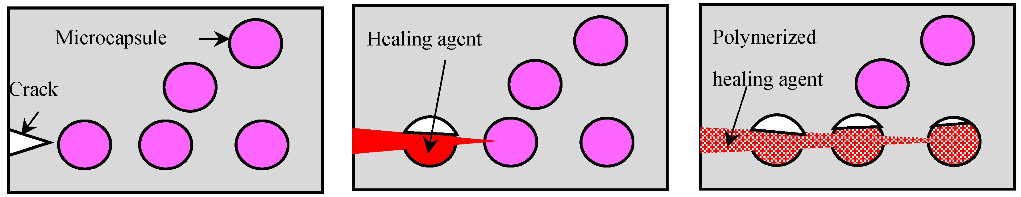
1]. However, its weakest point is that it is subject to cracking and deterioration with time, and the repair of concrete buildings is costly, especially for infrastructures, which are difficult to access. Recently, biological systems have become the inspiration for material scientists, which has resulted in the creation of self-healing materials. There are many strategies and techniques for self-healing concrete and they are classified in different ways. However, the encapsulation-based self-healing concrete has lately received much interest because of its capacity to effectively heal fractures without human intervention, extending the operational life and lowering maintenance costs. The propagating cracks hit the capsule shells releasing the healing agents to heal the cracks in the vicinity of the damaged part, see
Figure 1; as a result, it has promising prospects for infrastructures.
Several experimental and numerical studies have been carried out in the literature to investigate the fracture of the capsules and the healing capability of the capsules. These studies have revealed that the bond between the capsule shell and the cement matrix is not always perfect and the efficiency of healing depends on the fracture of microcapsules and the release of the healing agent in order to heal the cracks [
2,
3]. In this regard, a recent overview of the debonding behavior of fiber-reinforced polymer (FRP) systems used for strengthening existing structures can be found in [
4]. The concrete damage plasticity model (CDP) is integrated with finite element modeling to study the behavior and efficiency of CFRP as a strengthening technique for reinforced concrete beams subjected to blast loading, and the obtained results were in good correlation with experimental results [
5,
6]. Several numerical modeling methods have been developed recently to study the fracture mechanisms, such as the meshless methods, which have been used to study the fracture features of a marble semi-circular bend (SCB) specimen under a compressive loading condition. This showed that the geometrical definitions of the specimen can affect the fracture toughness [
7]. An identification methodology of cohesive zone model (CZM) parameters has been proposed to study the debonding of adhesively bonded structures. It is based on the comparison of experimental results obtained with help from the digital image correlation (DIC) technique and FEM modeling [
8]. Likewise, finite element analysis has been used to obtain the mixed-mode fracture parameters for sandstone specimens by introducing an inclined crack, whereas the fracture toughness was obtained experimentally [
9]. A cohesive/volumetric modeling technique based on a diffuse interface fracture approach has been used to model debonding mechanisms in FRP-strengthened RC structural elements [
10]. The extended finite element method (XFEM) and cohesive zone method (CZM) have been used to simulate the fracture and delamination in fiber metal laminates (FML). The obtained numerical results were in good agreement with the experimental observations [
11].
An interesting review study has shown the potential of phase-field methods for modeling fracture recovery in self-healing concrete. Although this method still required further development before it can be used as a simulation tool [
12]. Cohesive surfaces were introduced between the interfaces of all triangular elements of the finite element mesh to study the fast crack growth in brittle solids. This generated zigzag crack growth and the obtained results are in accord with experimental observations [
13]. The diffuse cohesive interface approach, which is also well-known in the literature, is the so-called zero-thickness cohesive element approach, has been used to predict the structural response of the ultra high-performance fiber-reinforced concrete (UHPFRC) structures enhanced with embedded nanomaterials [
14].
Computational modelling of SHC is still in the earlier stages and most of them have used the zero-thickness cohesive element approach. However, that approach has significant drawbacks, such as introducing artificial compliance and mesh dependency [
15]. The extended finite element method (XFEM) is a promising, flexible, and powerful discrete crack method, and it allows crack propagation without the requirement for re-meshing; in addition, it has been already implemented into commercial software such as Abaqus [
16]. There are a few limitations of the XFEM, which can be found in [
17]. These limitations can be classified mainly into two main categories; the first is about the crack propagation near to the element boundary. The second is about enabling the initiation of multiple cracks in the same enrichment zone; for a more detailed explanation refer to [
3]. Most of the computational modelling in SHC is focused on studying the fracture mechanism of the microcapsules and the interaction between them and the concrete. The zero-thickness cohesive element approach has been used to model the fracture of the microcapsules and the interaction between the capsules and the concrete [
18]. The XFEM and cohesive surface technique have been used to study the fracture mechanism of encapsulation-based self-healing materials [
3]. Although the XFEM and the zero-thickness cohesive element approach are based on the cohesive traction-separation law and the fracture energy as a damage criterion, the XFEM has been shown to have high accuracy for modelling fractures in concrete [
19]. Another study has employed the XFEM and the zero-thickness cohesive element approach for a configuration consisting of an infinite matrix with an inserted crack and a microcapsule [
20].
Since the fracture of the capsules is a critical issue for the healing mechanism, which happens by releasing the healing agent once the capsules are fractured. Therefore, fracture modelling is important, especially for the design of self-healing structures. This is due to the random distribution of the capsules inside the concrete matrix, which can lead to different crack patterns. This random distribution occurs during the mixing process of the concrete, which can lead to capsular clustering. The capsular clustering could be one of the main reasons that generate imperfect bonding between the capsules and the concrete. There are no studies conducted in the literature about the capsular clustering effects within the SHC context.
The main novelty of this study is to investigate the effects of capsular clustering on the fracture of encapsulation-based self-healing concrete. In this study, the effects of microcapsule size and clustering on the load-carrying capacity and the probability of fracture or debonding of the microcapsules from the concrete matrix are studied computationally. The computational simulations are performed for 2D modelling of SHC concrete samples with microcapsules loaded under uniaxial tension. The XFEM is used to model the concrete matrix and the microcapsule shell, and the contact surface between them is modelled by the cohesive surface technique. A precrack is not necessary with the XFEM to initiate the crack; however, in this study, an initial precrack was placed at the middle edge of the samples just for comparison purposes when a crack starts to initiate from the same edge.
2. Clustering Pattern/Degree of Clustering
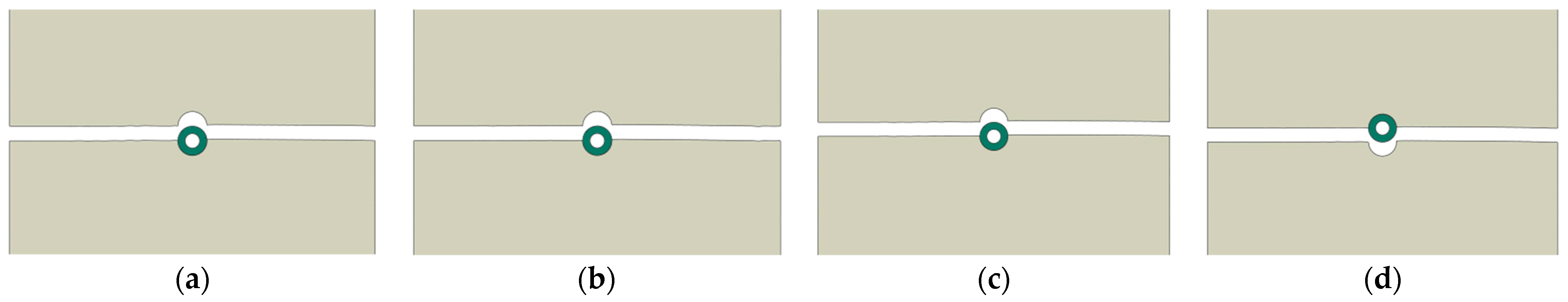
The mixing process of the concrete with the microcapsules can generate non-uniform distribution, which can easily form capsular clustering regions. These clustering formulations could happen in various assemblies, starting from simple degrees of clustering with only two microcapsules in contact and so on, see
Figure 2. In these clustering regions, the distance between microcapsules could be less than the diameter of the microcapsules themselves. In this case, the intermediate concrete matrix could become weaker and more susceptible to fail first, before allowing the tensile stress to be transferred from the concrete to the microcapsules, which eventually will be deboned from the concrete matrix without being fractured. In such a case, the healing agent will not release and the healing process will not occur. In order to model this clustering pattern, multiple models need to be generated with different densities and degrees of clustering. That means the microcapsular interdistance could be less than the diameter of the microcapsules or even zero, which means the microcapsules are completely clustered and touch each other. Generating these models is a headache. In addition, the very small distance between the microcapsules in the regions where capsules are more densely clustered will lead to a complication during the meshing of the model and be computationally expensive.
In order to avoid these complications, the most critical complete clustering patterns were studied geometrically, as illustrated in
Figure 2. In that figure, the effects of the capsular clustering from the neighbor blue microcapsules on the central black microcapsule of interest. It is obvious that increasing the number of the neighbor microcapsules will lead to decreasing the contact surface between the concrete and the central microcapsule of interest. Based on this geometrical observation, a simple procedure to model the capsular clustering can be proposed. In this proposed model, the samples will contain only a singular microcapsule and the contact surface between this microcapsule and the concrete will be changed accordingly to represent different degrees of capsular clustering. Degrees of capsular clustering can be varied from zero clustering to fully clustering. These are two extreme situations that represent that the microcapsule has a complete contact interface with the concrete matrix and a zero-contact interface with the concrete matrix, respectively. The capsular circumferential contact length (Lcs) between the microcapsule and the concrete will be used to define the degree of clustering. The parameter Lcs ration represents the actual contact length between the microcapsule shell and the concrete matrix over the circumference length of the microcapsule. The range of Lcs ration can be varied from 100 to 0%. These are the two extreme limits, which represent that the microcapsule has a complete contact interface with the concrete matrix (non-clustered) and a zero contact interface with the concrete matrix (fully clustered), as shown in
Figure 2a,g, respectively.
3. Modelling Framework
In this study, the specimens are modelled as three-phase composites consisting of concrete matrix, microcapsule shell, and an interface between them. Two computational techniques are used to perform the simulations. The eXtended Finite Element Method (XFEM) has been used to model the crack propagation in both parts; the concrete and the microcapsule. The interaction between these two parts is modelled by the cohesive surface technique, as shown in
Figure 3. Both the XFEM and cohesive surface technique are based on a traction-separation law for damage modelling.
3.1. The eXtended Finite Element Method (XFEM)
The extended finite element method (XFEM) is an extension of the conventional finite element method based on the concept of partition of unity, which allows local enrichment functions to be easily incorporated into a finite element approximation. The cracks are represented by enrichment functions, which are added to the normal displacement interpolation function, see Equation (1) [
21]. That allows the cracks to be represented within mesh elements without remeshing during the simulation. The XFEM has been implemented into commercial software such as Abaqus and has become one of the most popular methods for fracture [
16].
NI(x) are shape functions, uI is a nodal displacement vector, H(x) are jump functions to represent the cracks, aI and bIα are nodal vectors of the enriched degree of freedom, and Fα(x) are crack-tip functions.
3.2. Cohesive Surface Technique (CS)
The cohesive surface method is used to represent a zero-thickness layer between two surfaces that are initially in contact. As a result, in this study, the CS approach is used to represent the interaction between the microcapsule and the concrete matrix. Interactions, which are assigned a cohesive surface interaction property in Abaqus, are modelled with pure master–slave roles in the contact formulation. In this study, the external surface of the capsule is defined as a slave surface and the internal surface of the concrete matrix is defined as a master surface.
3.3. Traction-Separation Law
The failure mechanism for damage modelling consists of two steps in Abaqus: damage initiation criterion, and damage evolution. The traction–separation relationship has two zones: the linear elastic traction zone, and the damage evolution zone (softening), see
Figure 4. The elastic behavior of a cracked element is expressed in terms of an elastic constitutive matrix that connects normal and shear stresses to normal and shear separations. In the case of 3D, the nominal traction stress vector (
t) is composed of three components:
tn,
ts, and
tt, which represent the normal and shear tractions in two directions, respectively. The corresponding separations are denoted by
δn,
δs, and
δt. The elastic behavior can then be written as:
The elastic response is governed by the stiffness
Knn,
Kss, and
Ktt, the so-called penalty stiffness, whose value is calculated as a function of the two adjacent material stiffnesses [
22]. It has been proved that its value has no influence on the overall sample stiffness [
23] and their values have been taken at 1 × 10
6 MPa/mm in this study. Furthermore, the normal and shear penalty stiffnesses are assumed to be decoupled, meaning that a pure normal opening of the interface does not produce shear forces, and vice versa [
3]. It is assumed that the initial response is linear [
17]. However, damage can be represented by various damage evolution laws, such as a linear and nonlinear traction-separation response, once a damage initiation criterion has been met. In this study, the bilinear traction-separation law will be used, see
Figure 4.
3.3.1. Damage Initiation (Separation Initiation)
Damage initiation is defined as part of the interaction properties, using damage for the traction-separation law. There are a lot of damage initiation criteria available in the literature that are implemented in Abaqus as well, such as the maximum nominal stress criterion, quadratic stress criterion, maximum separation criterion, and quadratic separation criterion. In this thesis, the maximum nominal stress damage criterion is used. With this option, the damage will initiate when the maximal nominal stress exceeds the critical value, which is the maximum strength of the material.
Figure 4 shows the typical traction-separation response for all three directions to the contact faces. A crack can appear when the maximum principal stress calculated in its integration points meets the criterion of Equation (3), in the case of the XFEM, or Equation (4), in the case of the cohesive surface technique. A more detailed explanation of these techniques can be found in [
17]. The initiation and propagation criteria for the cohesive surface technique are combined in a single formulation and defined in the interaction module of Abaqus.
σmaxps is the calculated maximum principal stress and σ* is the maximum strength of the material. n, s, t: normal, shear, and tangential components of the interfacial tractions, respectively. (*) represents the maximum interfacial tractions. A purely compressive displacement (contact penetration) or a purely compressive stress state does not initiate damage, as indicated by the Macaulay bracket ⟨⟩.
3.3.2. Damage Evolution (Separation Propagation)
Once the initiation criterion is met, the damage evolution law describes the rate at which the cohesive stiffness degrades. The overall damage at the contact point is represented by
D, a scalar damage variable. It starts with a value of 0 and develops from 0 to 1 during the loading process. The fracture energy, which is the area under the curve in a graph of traction versus separation, or the maximal displacement must be specified. The normal and shear stresses components are affected by the damage according to [
17]. In this paper, the fracture energy is defined for damage evolution and it is assumed to be a linear softening for the damage evolution zone. To describe the evolution of damage under a combination of normal and shear separations across the interface, an effective separation is defined according to [
24] as:
represents the effective separation, is the maximum effective separation during the loading, and are the normal, shear, and tangential components of the interfacial separation directions, respectively. is the effective separation just before unloading, and is the effective separation at the damage initiation stage. Where and are the contact stress components predicted by the elastic traction-separation behavior for the current separations without damage. A Macaulay bracket ⟨⟩ is used to prevent compressive damage.
The hatched area below the curve in
Figure 4 provides the energy dissipated to produce a new pair of fully disconnected surfaces, so-called, interface fracture toughness. A mixed-mode propagation response of the cohesive interface can be generated due to the positioning of the interface for capsules with respect to the applied load. The propagation mixed mode involves different energies associated with the debonding capability in normal (
n) and parallel directions to the interface (
s,
t). The maximum fracture separation is then calculated by [
24]:
This paper assumes that the interaction between the energies of each individual mode (i.e.,
n,
s, and
t) follows the power-law fracture criterion [
24] given by:
where
Gn,
GS, and
Gt are the energy release rates calculated from the traction and normal, shear, and tangential displacements during interface opening, respectively, and the power
α is a cohesive property parameter that describes the interaction between modes. The critical interface toughness for each direction is represented by the properties
. In this paper, it is assumed that the critical fracture toughness is the same in all directions. In addition, taking into account the effect of this parameter on the response, a value
α = 1 has been used [
24].
3.4. Implementation in Abaqus
In Abaqus, models with various forms of softening behavior and stiffness degradation frequently cause severe convergence issues. Some of these convergence issues can be overcome by using viscous regularization of the constitutive equations defining surface-based cohesive behavior. For sufficiently small time increments, viscous regularization damping causes the tangent stiffness matrix that defines the contact stresses to be positive. In this study, the viscosity coefficient value is taken as 0.0001 [
17]. It is worth mentioning that some numerical convergence issues occurred that were related to the cohesive modelling behavior in Abaqus, such as:
- -
Time increment required is less than the minimum specified.
In order to solve this issue, the initial and minimum time increments should be defined as small values within the Step module > Edit > Step-1 > Incrementation. In this study, the initial time increment is taken to be 1 × 10⁻⁹ and the minimum time increment is taken to be 1 × 10⁻¹⁵.
- -
Too many attempts were made for this increment.
In order to solve this issue, the variable IA, which is the maximum number of cutbacks allowed for an increment within the Step module > Other > General Solution Controls > Edit > Step-1, has to be changed to a higher number to allow many numerical attempts, in this thesis it is taken to be 30.
6. Conclusions
A simple computational modelling approach for studying the capsular clustering effects on the fracture mechanism of encapsulation-based self-healing concrete is developed in this paper. Two-dimensional specimens of a three-phase composite consist of a concrete matrix, a microcapsule shell, and an interface between them. The eXtended Finite Element Method (XFEM) is used to model the concrete and the capsule parts, while the interface between them is modelled by the cohesive surface technique. The microcapsule circumferential contact length (Lcs), which represents the interface contact surface between the microcapsule and the concrete, is used to define the degree of microcapsule clustering. The microcapsule size is defined by the core/shell ratio; the following conclusions are made:
The microcapsule circumferential contact length (Lcs) between the microcapsule shell and the concrete matrix has a significant role in governing the load-carrying capacity of the specimen. The load-carrying capacity of the sample with the microcapsule core/shell ratio 1:1 and Lcs 100% is reduced by 4.6% in the case of Lcs 25%. While the load-carrying capacity of the sample with the microcapsule core/shell ratio 15:1 and Lcs 100% is reduced by 1.1% in the case of Lcs 25%. This shows the higher the Lcs (i.e., the lower the degree of microcapsule clustering), the higher the load-carrying capacity, and vice versa.
The Lcs also affects the crack pattern; however, it is not recommended that the microcapsule core/shell ratio be 1:1, which has the largest shell thickness but the smallest volume of the healing agent. Consequently, the debonding of the microcapsule from the concrete will happen regardless of the ratio of Lcs. Otherwise, when the Lcs is lower than 25% of the microcapsule circumference, it will result in a greater possibility for the debonding of the microcapsule from the concrete.
The microcapsule size has an impact on the load-carrying capacity of SHC specimens. The load-carrying capacity for the sample with Lcs 100% and the microcapsule core/shell ratio 1:1 is reduced by 3.8% in the case of the microcapsule core/shell ratio 15:1. While the load-carrying capacity for the sample with Lcs 25% and the microcapsule core/shell ratio 1:1 is reduced by 0.28% in the case of the microcapsule core/shell ratio of 15:1. It is obvious that the lower the core/shell ratio (larger shell thickness) of the microcapsule, the higher the load-carrying capacity of the specimen, and vice versa.
The microcapsule core/shell ratio has also a significant effect on the crack pattern as it determines whether the microcapsule will fracture, or debond from, the concrete. The greater the core/shell ratio (smaller shell thickness), the greater the likelihood of microcapsules being fractured.
It can be concluded from studying the effects of the microcapsule circumferential contact length and the microcapsule core/shell ratio on the load-carrying capacity that the microcapsule clustering has a higher effect than the microcapsule size on the load-carrying capacity of the SHC samples.
It is important not only to take care of microcapsules size, but also the clustering effects during the mixing process of the SHC, to minimize its effects on the contact surface between the microcapsule and the concrete to ensure the breakage of the microcapsules and the subsequent release of the healing agent.
As a possible future perspective of this research, the proposed computational framework for modeling the fracture mechanism in encapsulation-based SHC could be used to investigate the minimum microcapsule interdistance that should be considered in the design issue to obtain an effective fracture healing mechanism. The insufficient distance between the microcapsules in the regions where the microcapsules are clustered or close to each other could generate imperfect bonding between the capsules and the concrete, as the intermediate matrix is more vulnerable to damage and may leave the microcapsules intact. Another future perspective of this research is that the proposed computational framework could be expanded to perform 3D simulations and to compare the obtained results with those obtained from 2D simulations in order to estimate the accuracy difference ratio between 2D and 3D simulations. Depending more on reliable 2D modeling will reduce the computational costs resulting from 3D modeling.


